


RAS-18
Toshiba RAS-18, 22SKV-E, 22SKVR-E, 22SKVR-A, 22SKV-N Service Manual
...
R410A
Revised on May, 2010
AIR-CONDITIONER
SPLIT TYPE
SERVICE MANUAL
Indoor Unit
<High Wall, Heat Pump Type>
RAS-18, 22SKV-E
RAS-18, 22SKVR-
E
RAS-18, 22SKV
2-E
RAS-18, 22SKV
-A
Outdoor Unit
<Heat Pump Type>
RAS-18, 22SAV-E2
RAS-18, 22SAV2-E
RAS-18, 22SKVR-A
RAS-18, 22SKV-ND
RAS-18, 22SAV2-
A
FILE NO. SVM-10050-1

– 2 –
CONTENTS
1. SAFETY PRECAUTIONS .......................................................................... 3
2. SPECIFICATIONS...................................................................................... 5
3. REFRIGERANT R410A ........................................................................... 12
4. CONSTRUCTION VIEWS ........................................................................ 20
5. WIRING DIAGRAM .................................................................................. 23
6. SPECIFICATIONS OF ELECTRICAL PARTS ......................................... 24
7. REFRIGERANT CYCLE DIAGRAM ........................................................ 25
8. CONTROL BLOCK DIAGRAM ................................................................ 28
9. OPERATION DESCRIPTION ................................................................... 31
10. INSTALLATION PROCEDURE ................................................................ 56
11. HOW TO DIAGNOSE THE TROUBLE ...................................................... 69
12. HOW TO REPLACE THE MAIN PARTS ................................................... 93
13. EXPLODED VIEWS AND PARTS LIST ................................................. 110
FILE NO. SVM-10050
– 3 –
1. SAFETY PRECAUTIONS
For general public use
Power supply cord of outdoor unit shall be more than 1.5 mm ² (H07RN-F or 60245IEC66) polychloroprene
sheathed flexible cord.
• Read this “SAFETY PRECAUTIONS” carefully before servicing.
• The precautions described below include the important items regarding safety. Observe them without fail.
• After the servicing work, perform a trial operation to check for any problem.
• Turn off the main power supply switch (or breaker) before the unit maintenance.
CAUTION
New Refrigerant Air Conditioner Installation
• THIS AIR CONDITIONER ADOPTS THE NEW HFC REFRIGERANT (R410A) WHICH DOES NOT
DESTROY OZONE LAYER.
R410A refrigerant is apt to be affected by impurities such as water, oxidizing membrane, and oils because
the working pressure of R410A refrigerant is approx. 1.6 times of refrigerant R22. Accompanied with the
adoption of the new refrigerant, the refrigeration machine oil has also been changed. Therefore, during
installation work, be sure that water, dust, former refrigerant, or refrigeration machine oil does not enter
into the new type refrigerant R410A air conditioner circuit.
To prevent mixing of refrigerant or refrigerating machine oil, the sizes of connecting sections of charging
port on main unit and installation tools are different from those used for the conventional refrigerant units.
Accordingly, special tools are required for the new refrigerant (R410A) units. For connecting pipes, use new
and clean piping materials with high pressure fittings made for R410A only, so that water and/or dust does
not enter. Moreover, do not use the existing piping because there are some problems with pressure fittings
and possible impurities in existing piping.
CAUTION
TO DISCONNECT THE APPLIANCE FROM THE MAIN POWER SUPPLY
This appliance must be connected to the main power supply by a circuit breaker or a switch with a contact
separation of at least 3 mm.
DANGER
• ASK AN AUTHORIZED DEALER OR QUALIFIED INSTALLATION PROFESSIONAL TO INSTALL/
MAINTAIN THE AIR CONDITIONER.
INAPPROPRIATE SERVICING MAY RESULT IN WATER LEAKAGE, ELECTRIC SHOCK OR FIRE.
• TURN OFF MAIN POWER SUPPLY BEFORE ATTEMPTING ANY ELECTRICAL WORK. MAKE SURE
ALL POWER SWITCHES ARE OFF. FAILURE TO DO SO MAY CAUSE ELECTRIC SHOCK.
DANGER: HIGH VOLTAGE
The high voltage circuit is incorporated.
Be careful to do the check service, as the electric shock may be caused in case of touching parts
on the P.C. board by hand.
• CORRECTLY CONNECT THE CONNECTING CABLE. IF THE CONNECTING CABLE IS INCORRECTLY CONNECTED, ELECTRIC PARTS MAY BE DAMAGED.
• CHECK THAT THE EARTH WIRE IS NOT BROKEN OR DISCONNECTED BEFORE SERVICE AND
INSTALLATION. FAILURE TO DO SO MAY CAUSE ELECTRIC SHOCK.
FILE NO. SVM-10050
– 4 –
• DO NOT INSTALL NEAR CONCENTRATIONS OF COMBUSTIBLE GAS OR GAS VAPORS. FAILURE
TO FOLLOW THIS INSTRUCTION CAN RESULT IN FIRE OR EXPLOSION.
• TO PREVENT THE INDOOR UNIT FROM OVERHEATING AND CAUSING A FIRE HAZARD, PLACE
THE UNIT WELL AWAY (MORE THAN 2 M) FROM HEAT SOURCES SUCH AS RADIATORS, HEAT
REGISTERS, FURNACE, STOVES, ETC.
• WHEN MOVING THE AIR CONDITIONER FOR INSTALLATION IN ANOTHER PLACE, BE VERY CAREFUL NOT TO ALLOW THE SPECIFIED REFRIGERANT (R410A) TO BECOME MIXED WITH ANY
OTHER GASEOUS BODY INTO THE REFRIGERATION CIRCUIT. IF AIR OR ANY OTHER GAS IS
MIXED IN THE REFRIGERANT, THE GAS PRESSURE IN THE REFRIGERATION CIRCUIT WILL
BECOME ABNORMALLY HIGH AND IT MAY RESULT IN THE PIPE BURSTING AND POSSIBLE
PERSONNEL INJURIES.
• IN THE EVENT THAT THE REFRIGERANT GAS LEAKS OUT OF THE PIPE DURING THE SERVICE
WORK AND THE INSTALLATION WORK, IMMEDIATELY LET FRESH AIR INTO THE ROOM.
IF THE REFRIGERANT GAS IS HEATED, SUCH AS BY FIRE, GENERATION OF POISONOUS GAS
MAY RESULT.
WARNING
• Never modify this unit by removing any of the safety guards or bypass any of the safety interlock
switches.
• Do not install in a place which cannot bear the weight of the unit. Personal injury and property
damage can result if the unit falls.
• After the installation work, confirm that refrigerant gas does not leak.
If refrigerant gas leaks into the room and flows near a fire source, such as a cooking range, noxious gas
may generate.
• The electrical work must be performed by a qualified electrician in accordance with the Installation Manual. Make sure the air conditioner uses an exclusive circuit.
An insufficient circuit capacity or inappropriate installation may cause fire.
• When wiring, use the specified cables and connect the terminals securely to prevent external
forces applied to the cable from affecting the terminals.
• Be sure to provide grounding.
Do not connect ground wires to gas pipes, water pipes, lightning rods or ground wires for telephone cables.
• Conform to the regulations of the local electric company when wiring the power supply.
Inappropriate grounding may cause electric shock.
CAUTION
• Exposure of unit to water or other moisture before installation may result in an electrical short.
Do not store in a wet basement or expose to rain or water.
• Do not install in a place that can increase the vibration of the unit. Do not install in a place that can
amplify the noise level of the unit or where noise or discharged air might disturb neighbors.
• To avoid personal injury, be careful when handling parts with sharp edges.
• Perform the specified installation work to guard against an earthquake.
If the air conditioner is not installed appropriately, accidents may occur due to the falling unit.
For Reference:
If a heating operation would be continuously performed for a long time under the condition that the outdoor
temperature is 0°C or lower, drainage of defrosted water may be difficult due to freezing of the bottom
plate, resulting in a trouble of the cabinet or fan.
It is recommended to procure an antifreeze heater locally for a safe installation of the air conditioner.
For details, contact the dealer.
FILE NO. SVM-10050

– 5 –
Unit model
Indoor
Outdoor
Cooling capacity (kW)
Cooling capacity range (kW)
Heating capacity (kW)
Heating capacity range (kW)
Power supply
Operation mode
Indoor
Running current (A)
Power consumption (W)
Electric
Power factor (%)
Operation mode
characteristic
Running current (A)
Outdoor Power consumption (W)
Power factor (%)
Starting current (A)
COP
Sound pressure
Indoor H / M+ / M / L+ / L (dB-A)
level
Outdoor H (dB-A)
Sound power
Indoor H / M+ / M / L+ / L (dB-A)
level
Outdoor H (dB-A)
Unit model
Height (mm)
Dimension Width (mm)
Indoor unit Depth (mm)
Net weight (kg)
Fan motor output (W)
Air flow rate (Cooling/Heating) (m³/min)
Unit model
Height (mm)
Dimension Width (mm)
Depth (mm)
Outdoor unit
Net weight (kg)
Motor output (W)
Compressor Type
Model
Fan motor output (W)
Air flow rate (Cooling/Heating) (m³/min)
Type
Indoor unit
Liquid side (mm)
Gas side (mm)
Piping
Outdoor unit
Liquid side (mm)
connection Gas side (mm)
Maximum length (m)
Maximum chargeless length (m)
Maximum height difference (m)
Refrigerant
Name of refrigerant
Weight (kg)
Wiring connection
Power supply
Interconnection
Usable temperature range
Indoor (Cooling/Heating) (°C)
Outdoor (Cooling/Heating) (°C)
Installation plate
Wireless remote controller
Batteries
Remote controller holder
Toshiba New IAQ filter
Indoor unit
Accessory
Remote controller holder
Pan head wood screw
Plasma air purifier
Installation manual
Owner’s manual
Outdoor unit
Drain nipple
RAS-18SKV-E RAS-22SKV-E
RAS-18SAV-E2 RAS-22SAV-E2
5.0 6.0
1.1 – 6.0 1.2 – 6.7
5.8 7.0
0.8 – 6.3 1.0 – 7.5
1 Ph / 50Hz / 220 – 240V, 1 Ph / 60Hz / 220 – 230V
Cooling Heating Cooling Heating
0.30 – 0.28 0.30 – 0.28 0.38 – 0.35 0.38 – 0.35
40 40 50 50
60 60 60 60
Cooling Heating Cooling Heating
6.40 – 5.87 6.98 – 6.40 8.93 – 8.19 9.18 – 8.42
1380 1520 1945 2000
98 99 99 99
7.28-6.68 9.56-8.77
3.52 3.72 3.01 3.41
44/41/38/35/32 44/41/39/35/32 47/44/41/38/35 47/44/42/38/35
49 50 53 52
59/56/53/50/47 59/56/54/50/47 62/59/56/53/50 62/59/57/53/50
64 65 68 67
RAS-18SKV-E RAS-22SKV-E
320 320
1050 1050
228 228
13 13
30 30
15.9 / 16.5 17.7 / 18.0
RAS-18SAV-E2 RAS-22SAV-E2
550 550
780 780
290 290
41 41
1100 1100
Twin rotary type with DC-inverter variable speed control
DA130A1F-27F DA150A1F-20F
43 43
36.3 / 31.9 38.6 / 37.2
Flare connection Flare connection
Ø6.35 Ø6.35
Ø12.70 Ø12.70
Ø6.35 Ø6.35
Ø12.70 Ø12.70
20 20
15 15
10 10
R410A R410A
1.40 1.40
3 Wires: includes earth (Outdoor)
4 Wires: includes earth
21 ~ 32 / ~ 28 21 ~ 32 / ~ 28
–10 ~ 46 / –15 ~ 24 –10 ~ 46 /–15 ~ 24
11
11
22
11
44
6 (Ø4 × 25L) 6 (Ø4 × 25L)
2 (Ø3.1L × 16L) 2 (Ø3.1L × 16L)
—
11
11
11
Mounting screw
—
22
Water-proof rubber cap
FILE NO. SVM-10050
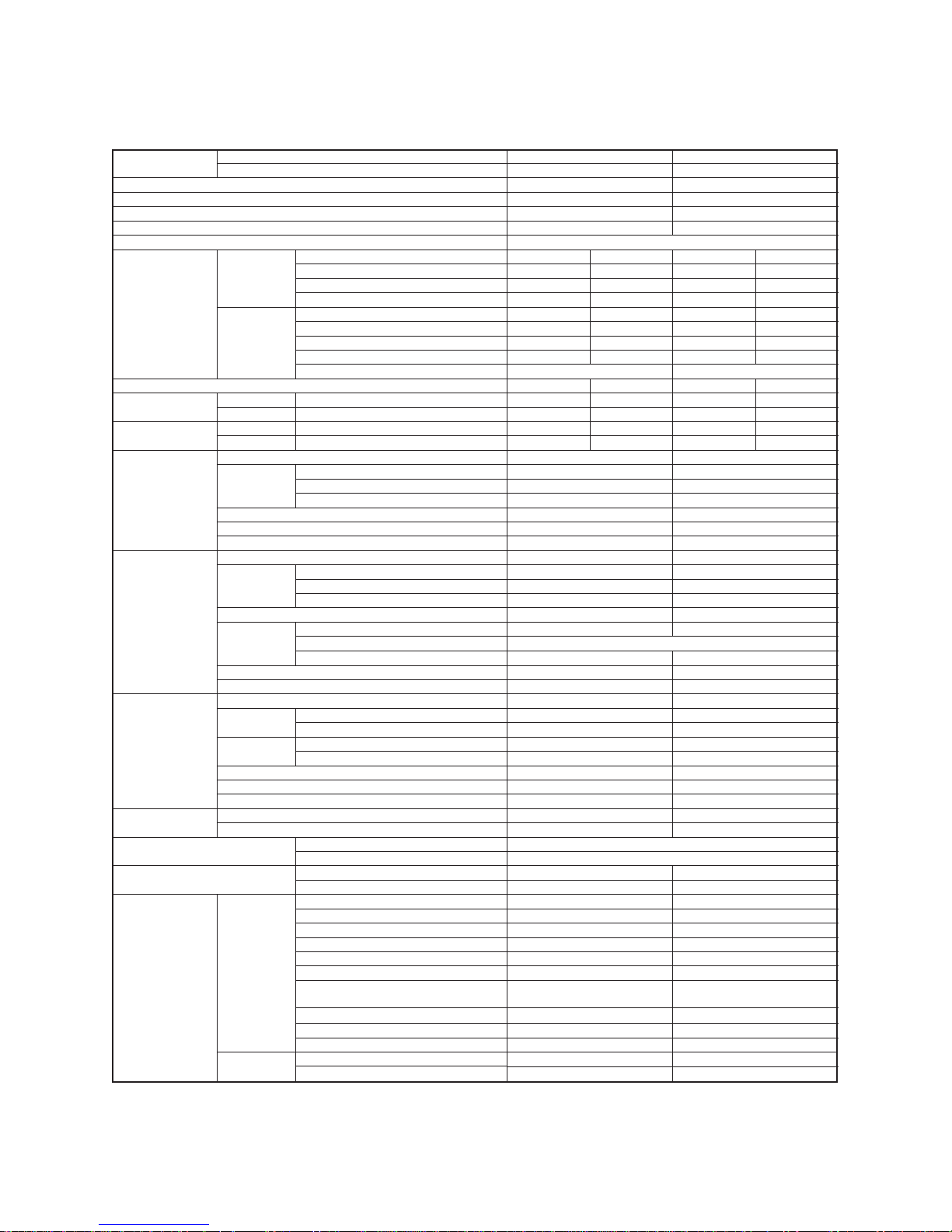
• The specifications may be subject to change without notice for purpose of improvement.
2-1. Specifications
RAS-18SKV-E / RAS-18SAV-E2
RAS-22SKV-E / RAS-22SAV-E2
2. SPECIFICATIONS
Unit model
Indoor
Outdoor
Cooling capacity (kW)
Cooling capacity range (kW)
Heating capacity (kW)
Heating capacity range (kW)
Power supply
Operation mode
Indoor
Running current (A)
Power consumption (W)
Electric
Power factor (%)
Operation mode
characteristic
Running current (A)
Outdoor Power consumption (W)
Power factor (%)
Starting current (A)
COP
Sound pressure
Indoor H / M+ / M / L+ / L (dB-A)
level
Outdoor H (dB-A)
Sound power
Indoor H / M+ / M / L+ / L (dB-A)
level
Outdoor H (dB-A)
Unit model
Height (mm)
Dimension Width (mm)
Indoor unit Depth (mm)
Net weight (kg)
Fan motor output (W)
Air flow rate (Cooling/Heating) (m³/min)
Unit model
Height (mm)
Dimension Width (mm)
Depth (mm)
Outdoor unit
Net weight (kg)
Motor output (W)
Compressor Type
Model
Fan motor output (W)
Air flow rate (Cooling/Heating) (m³/min)
Type
Indoor unit
Liquid side (mm)
Gas side (mm)
Piping
Outdoor unit
Liquid side (mm)
connection Gas side (mm)
Maximum length (m)
Maximum chargeless length (m)
Maximum height difference (m)
Refrigerant
Name of refrigerant
Weight (kg)
Wiring connection
Power supply
Interconnection
Usable temperature range
Indoor (Cooling/Heating) (°C)
Outdoor (Cooling/Heating) (°C)
Installation plate
Wireless remote controller
Batteries
Remote controller holder
Indoor unit
Accessory
Remote controller holder
Pan head wood screw
Plasma air purifier
Installation manual
Owner’s manual
Outdoor unit
Drain nipple
RAS-18SKVR-E RAS-22SKVR-E
RAS-18SAV-E2 RAS-22SAV-E2
5.0 6.0
1.1 – 6.0 1.2 – 6.7
5.8 7.0
0.8 – 6.3 1.0 – 7.5
1 Ph / 50Hz / 220 – 240V, 1 Ph / 60Hz / 220 – 230V
Cooling Heating Cooling Heating
0.30 – 0.28 0.30 – 0.28 0.38 – 0.35 0.38 – 0.35
40 40 50 50
60 60 60 60
Cooling Heating Cooling Heating
6.40 – 5.87 6.98 – 6.40 8.93 – 8.19 9.18 – 8.42
1380 1520 1945 2000
98 99 99 99
7.28-6.68 9.56-8.77
3.52 3.72 3.01 3.41
44/41/38/35/32 44/41/39/35/32 47/44/41/38/35 47/44/42/38/35
49 50 53 52
59/56/53/50/47 59/56/54/50/47 62/59/56/53/50 62/59/57/53/50
64 65 68 67
RAS-18SKVR-E RAS-22SKVR-E
320 320
1050 1050
228 228
13 13
30 30
15.9 / 16.5 17.7 / 18.0
RAS-18SAV-E2 RAS-22SAV-E2
550 550
780 780
290 290
41 41
1100 1100
Twin rotary type with DC-inverter variable speed control
DA130A1F-27F DA150A1F-20F
43 43
36.3 / 31.9 38.6 / 37.2
Flare connection Flare connection
Ø6.35 Ø6.35
Ø12.70 Ø12.70
Ø6.35 Ø6.35
Ø12.70 Ø12.70
20 20
15 15
10 10
R410A R410A
1.40 1.40
3 Wires: includes earth (Outdoor)
4 Wires: includes earth
21 ~ 32 / ~ 28 21 ~ 32 / ~ 28
–10 ~ 46 / –15 ~ 24 –10 ~ 46 /–15 ~ 24
11
11
22
11
22
6 (Ø4 × 25L) 6 (Ø4 × 25L)
2 (Ø3.1L × 16L) 2 (Ø3.1L × 16L)
11
11
11
Mounting screw
22
Water-proof rubber cap
• The specifications may be subject to change without notice for purpose of improvement.
RAS-18SKVR-E / RAS-18SAV-E2
RAS-22SKVR-E / RAS-22SAV-E2
– 6 –
FILE NO. SVM-10050
11
Toshiba New IAQ filter

Unit model
Indoor
Outdoor
Cooling capacity (kW)
Cooling capacity range (kW)
Heating capacity (kW)
Heating capacity range (kW)
Power supply
Operation mode
Indoor
Running current (A)
Power consumption (W)
Electric
Power factor (%)
Operation mode
characteristic
Running current (A)
Outdoor Power consumption (W)
Power factor (%)
Starting current (A)
COP
Sound pressure
Indoor H / M+ / M / L+ / L (dB-A)
level
Outdoor H (dB-A)
Sound power
Indoor H / M+ / M / L+ / L (dB-A)
level
Outdoor H (dB-A)
Unit model
Height (mm)
Dimension Width (mm)
Indoor unit Depth (mm)
Net weight (kg)
Fan motor output (W)
Air flow rate (Cooling/Heating) (m³/min)
Unit model
Height (mm)
Dimension Width (mm)
Depth (mm)
Outdoor unit
Net weight (kg)
Motor output (W)
Compressor Type
Model
Fan motor output (W)
Air flow rate (Cooling/Heating) (m³/min)
Type
Indoor unit
Liquid side (mm)
Gas side (mm)
Piping
Outdoor unit
Liquid side (mm)
connection Gas side (mm)
Maximum length (m)
Maximum chargeless length (m)
Maximum height difference (m)
Refrigerant
Name of refrigerant
Weight (kg)
Wiring connection
Power supply
Interconnection
Usable temperature range
Indoor (Cooling/Heating) (°C)
Outdoor (Cooling/Heating) (°C)
Installation plate
Wireless remote controller
Batteries
Remote controller holder
Toshiba New IAQ filter
Indoor unit
Accessory
Remote controller holder
Pan head wood screw
Plasma air purifier
Installation manual
Owner’s manual
Outdoor unit
Drain nipple
RAS-18SKV2-E RAS-22SKV2-E
RAS-18SAV2-E RAS-22SAV2-E
5.0 6.0
1.1 – 6.0 1.2 – 6.7
5.8 7.0
0.8 – 6.3 1.0 – 7.5
1 Ph / 50Hz / 220 – 240V, 1 Ph / 60Hz / 220 – 230V
Cooling Heating Cooling Heating
0.30 – 0.28 0.30 – 0.28 0.38 – 0.35 0.38 – 0.35
40 40 50 50
60 60 60 60
Cooling Heating Cooling Heating
6.40 – 5.87 6.98 – 6.40 8.93 – 8.19 9.18 – 8.42
1380 1520 1945 2000
98 99 99 99
7.28-6.68 9.56-8.77
3.52 3.72 3.01 3.41
44/41/38/35/32 44/41/39/35/32 47/44/41/38/35 47/44/42/38/35
49 50 53 52
59/56/53/50/47 59/56/54/50/47 62/59/56/53/50 62/59/57/53/50
64 65 68 67
RAS-18SKV2-E RAS-22SKV2-E
320 320
1050 1050
228 228
13 13
30 30
15.9 / 16.5 17.7 / 18.0
RAS-18SAV2-E RAS-22SAV2-E
550 550
780 780
290 290
41 41
1100 1100
Twin rotary type with DC-inverter variable speed control
DA130A1F-27F DA150A1F-20F
43 43
36.3 / 31.9 38.6 / 37.2
Flare connection Flare connection
Ø6.35 Ø6.35
Ø12.70 Ø12.70
Ø6.35 Ø6.35
Ø12.70 Ø12.70
20 20
15 15
10 10
R410A R410A
1.40 1.40
3 Wires: includes earth (Outdoor)
4 Wires: includes earth
21 ~ 32 / ~ 28 21 ~ 32 / ~ 28
–10 ~ 46 / –15 ~ 24 –10 ~ 46 /–15 ~ 24
11
11
22
11
44
6 (Ø4 × 25L) 6 (Ø4 × 25L)
2 (Ø3.1L × 16L) 2 (Ø3.1L × 16L)
11
11
11
Mounting screw
22
Water-proof rubber cap
• The specifications may be subject to change without notice for purpose of improvement.
RAS-18SKV2-E / RAS-18SAV2-E
RAS-22SKV2-E / RAS-22SAV2-E
– 7 –
FILE NO. SVM-10050
——

Unit model
Indoor
Outdoor
Cooling capacity (kW)
Cooling capacity range (kW)
Heating capacity (kW)
Heating capacity range (kW)
Power supply
Operation mode
Indoor
Running current (A)
Power consumption (W)
Electric
Power factor (%)
Operation mode
characteristic
Running current (A)
Outdoor Power consumption (W)
Power factor (%)
Starting current (A)
COP
Sound pressure
Indoor H / M+ / M / L+ / L (dB-A)
level
Outdoor H (dB-A)
Sound power
Indoor H / M+ / M / L+ / L (dB-A)
level
Outdoor H (dB-A)
Unit model
Height (mm)
Dimension Width (mm)
Indoor unit Depth (mm)
Net weight (kg)
Fan motor output (W)
Air flow rate (Cooling/Heating) (m³/min)
Unit model
Height (mm)
Dimension Width (mm)
Depth (mm)
Outdoor unit
Net weight (kg)
Motor output (W)
Compressor Type
Model
Fan motor output (W)
Air flow rate (Cooling/Heating) (m³/min)
Type
Indoor unit
Liquid side (mm)
Gas side (mm)
Piping
Outdoor unit
Liquid side (mm)
connection Gas side (mm)
Maximum length (m)
Maximum chargeless length (m)
Maximum height difference (m)
Refrigerant
Name of refrigerant
Weight (kg)
Wiring connection
Power supply
Interconnection
Usable temperature range
Indoor (Cooling/Heating) (°C)
Outdoor (Cooling/Heating) (°C)
Installation plate
Wireless remote controller
Batteries
Remote controller holder
Toshiba New IAQ filter
Indoor unit
Accessory
Remote controller holder
Pan head wood screw
Plasma air purifier
Installation manual
Owner’s manual
Outdoor unit
Drain nipple
RAS-18SKV-A RAS-22SKV-A
RAS-18SAV2-A RAS-22SAV2-A
5.0 6.0
1.1 – 6.0 1.2 – 6.7
5.8 7.0
0.8 – 6.3 1.0 – 7.5
1 Ph / 50Hz / 220 – 240V
Cooling Heating Cooling Heating
0.30 – 0.28 0.30 – 0.28 0.38 – 0.35 0.38 – 0.35
40 40 50 50
60 60 60 60
Cooling Heating Cooling Heating
6.40 – 5.87 6.98 – 6.40 8.93 – 8.19 9.18 – 8.42
1380 1520 1945 2000
98 99 99 99
7.28-6.68 9.56-8.77
3.52 3.72 3.01 3.41
44/41/38/35/32 44/41/39/35/32 47/44/41/38/35 47/44/42/38/35
49 50 53 52
59/56/53/50/47 59/56/54/50/47 62/59/56/53/50 62/59/57/53/50
64 65 68 67
RAS-18SKV-A RAS-22SKV-A
320 320
1050 1050
228 228
13 13
30 30
15.9 / 16.5 17.7 / 18.0
RAS-18SAV2-A RAS-22SAV2-A
550 550
780 780
290 290
41 41
1100 1100
Twin rotary type with DC-inverter variable speed control
DA130A1F-27F DA150A1F-20F
43 43
36.3 / 31.9 38.6 / 37.2
Flare connection Flare connection
Ø6.35 Ø6.35
Ø12.70 Ø12.70
Ø6.35 Ø6.35
Ø12.70 Ø12.70
20 20
15 15
10 10
R410A R410A
1.40 1.40
3 Wires: includes earth (Outdoor)
4 Wires: includes earth
21 ~ 32 / ~ 28 21 ~ 32 / ~ 28
–10 ~ 46 / –15 ~ 24 –10 ~ 46 /–15 ~ 24
11
11
22
11
44
6 (Ø4 × 25L) 6 (Ø4 × 25L)
2 (Ø3.1L × 16L) 2 (Ø3.1L × 16L)
11
11
11
Mounting screw
22
Water-proof rubber cap
• The specifications may be subject to change without notice for purpose of improvement.
RAS-18SKV-A / RAS-18SAV2-A
RAS-22SKV-A / RAS-22SAV2-A
– 8 –
FILE NO. SVM-10050-1
——

Unit model
Indoor
Outdoor
Cooling capacity (kW)
Cooling capacity range (kW)
Heating capacity (kW)
Heating capacity range (kW)
Power supply
Operation mode
Indoor
Running current (A)
Power consumption (W)
Electric
Power factor (%)
Operation mode
characteristic
Running current (A)
Outdoor Power consumption (W)
Power factor (%)
Starting current (A)
COP
Sound pressure
Indoor H / M+ / M / L+ / L (dB-A)
level
Outdoor H (dB-A)
Sound power
Indoor H / M+ / M / L+ / L (dB-A)
level
Outdoor H (dB-A)
Unit model
Height (mm)
Dimension Width (mm)
Indoor unit Depth (mm)
Net weight (kg)
Fan motor output (W)
Air flow rate (Cooling/Heating) (m³/min)
Unit model
Height (mm)
Dimension Width (mm)
Depth (mm)
Outdoor unit
Net weight (kg)
Motor output (W)
Compressor Type
Model
Fan motor output (W)
Air flow rate (Cooling/Heating) (m³/min)
Type
Indoor unit
Liquid side (mm)
Gas side (mm)
Piping
Outdoor unit
Liquid side (mm)
connection Gas side (mm)
Maximum length (m)
Maximum chargeless length (m)
Maximum height difference (m)
Refrigerant
Name of refrigerant
Weight (kg)
Wiring connection
Power supply
Interconnection
Usable temperature range
Indoor (Cooling/Heating) (°C)
Outdoor (Cooling/Heating) (°C)
Installation plate
Wireless remote controller
Batteries
Remote controller holder
Toshiba New IAQ filter
Indoor unit
Accessory
Remote controller holder
Pan head wood screw
Plasma air purifier
Installation manual
Owner’s manual
Outdoor unit
Drain nipple
RAS-18SKVR-A RAS-22SKVR-A
RAS-18SAV2-A RAS-22SAV2-A
5.0 6.0
1.1 – 6.0 1.2 – 6.7
5.8 7.0
0.8 – 6.3 1.0 – 7.5
1 Ph / 50Hz / 220 – 240V
Cooling Heating Cooling Heating
0.30 – 0.28 0.30 – 0.28 0.38 – 0.35 0.38 – 0.35
40 40 50 50
60 60 60 60
Cooling Heating Cooling Heating
6.40 – 5.87 6.98 – 6.40 8.93 – 8.19 9.18 – 8.42
1380 1520 1945 2000
98 99 99 99
7.28-6.68 9.56-8.77
3.52 3.72 3.01 3.41
44/41/38/35/32 44/41/39/35/32 47/44/41/38/35 47/44/42/38/35
49 50 53 52
59/56/53/50/47 59/56/54/50/47 62/59/56/53/50 62/59/57/53/50
64 65 68 67
RAS-18SKVR-A RAS-22SKVR-A
320 320
1050 1050
228 228
13 13
30 30
15.9 / 16.5 17.7 / 18.0
RAS-18SAV2-A RAS-22SAV2-A
550 550
780 780
290 290
41 41
1100 1100
Twin rotary type with DC-inverter variable speed control
DA130A1F-27F DA150A1F-20F
43 43
36.3 / 31.9 38.6 / 37.2
Flare connection Flare connection
Ø6.35 Ø6.35
Ø12.70 Ø12.70
Ø6.35 Ø6.35
Ø12.70 Ø12.70
20 20
15 15
10 10
R410A R410A
1.40 1.40
3 Wires: includes earth (Outdoor)
4 Wires: includes earth
21 ~ 32 / ~ 28 21 ~ 32 / ~ 28
–10 ~ 46 / –15 ~ 24 –10 ~ 46 /–15 ~ 24
11
11
22
11
22
6 (Ø4 × 25L) 6 (Ø4 × 25L)
2 (Ø3.1L × 16L) 2 (Ø3.1L × 16L)
11
11
11
Mounting screw
22
Water-proof rubber cap
• The specifications may be subject to change without notice for purpose of improvement.
RAS-18SKVR-A / RAS-18SAV2-A
RAS-22SKVR-A / RAS-22SAV2-A
– 9 –
FILE NO. SVM-10050-1
11

Unit model
Indoor
Outdoor
Cooling capacity (kW)
Cooling capacity range (kW)
Heating capacity (kW)
Heating capacity range (kW)
Power supply
Operation mode
Indoor
Running current (A)
Power consumption (W)
Electric
Power factor (%)
Operation mode
characteristic
Running current (A)
Outdoor Power consumption (W)
Power factor (%)
Starting current (A)
COP
Sound pressure
Indoor H / M+ / M / L+ / L (dB-A)
level
Outdoor H (dB-A)
Sound power
Indoor H / M+ / M / L+ / L (dB-A)
level
Outdoor H (dB-A)
Unit model
Height (mm)
Dimension Width (mm)
Indoor unit Depth (mm)
Net weight (kg)
Fan motor output (W)
Air flow rate (Cooling/Heating) (m³/min)
Unit model
Height (mm)
Dimension Width (mm)
Depth (mm)
Outdoor unit
Net weight (kg)
Motor output (W)
Compressor Type
Model
Fan motor output (W)
Air flow rate (Cooling/Heating) (m³/min)
Type
Indoor unit
Liquid side (mm)
Gas side (mm)
Piping
Outdoor unit
Liquid side (mm)
connection Gas side (mm)
Maximum length (m)
Maximum chargeless length (m)
Maximum height difference (m)
Refrigerant
Name of refrigerant
Weight (kg)
Wiring connection
Power supply
Interconnection
Usable temperature range
Indoor (Cooling/Heating) (°C)
Outdoor (Cooling/Heating) (°C)
Installation plate
Wireless remote controller
Batteries
Remote controller holder
Toshiba New IAQ filter
Indoor unit
Accessory
Remote controller holder
Pan head wood screw
Plasma air purifier
Installation manual
Owner’s manual
Outdoor unit
Drain nipple
RAS-18SKV-ND RAS-22SKV-ND
RAS-18SAV2-E RAS-22SAV2-E
5.0 6.0
1.1 – 6.0 1.2 – 6.7
5.8 7.0
0.8 – 6.3 1.0 – 7.5
1 Ph / 50Hz / 220 – 240V, 1 Ph / 60Hz / 220 – 230V
Cooling Heating Cooling Heating
0.30 – 0.28 0.30 – 0.28 0.38 – 0.35 0.38 – 0.35
40 40 50 50
60 60 60 60
Cooling Heating Cooling Heating
6.40 – 5.87 6.98 – 6.40 8.93 – 8.19 9.18 – 8.42
1380 1520 1945 2000
98 99 99 99
7.28-6.68 9.56-8.77
3.52 3.72 3.01 3.41
44/41/38/35/32 44/41/39/35/32 47/44/41/38/35 47/44/42/38/35
49 50 53 52
59/56/53/50/47 59/56/54/50/47 62/59/56/53/50 62/59/57/53/50
64 65 68 67
RAS-18SKV-ND RAS-22SKV-ND
320 320
1050 1050
228 228
13 13
30 30
15.9 / 16.5 17.7 / 18.0
RAS-18SAV2-E RAS-22SAV2-E
550 550
780 780
290 290
41 41
1100 1100
Twin rotary type with DC-inverter variable speed control
DA130A1F-27F DA150A1F-20F
43 43
36.3 / 31.9 38.6 / 37.2
Flare connection Flare connection
Ø6.35 Ø6.35
Ø12.70 Ø12.70
Ø6.35 Ø6.35
Ø12.70 Ø12.70
20 20
15 15
10 10
R410A R410A
1.40 1.40
3 Wires: includes earth (Outdoor)
4 Wires: includes earth
21 ~ 32 / ~ 28 21 ~ 32 / ~ 28
–10 ~ 46 / –15 ~ 24 –10 ~ 46 /–15 ~ 24
11
11
22
11
44
6 (Ø4 × 25L) 6 (Ø4 × 25L)
2 (Ø3.1L × 16L) 2 (Ø3.1L × 16L)
11
11
11
Mounting screw
22
Water-proof rubber cap
• The specifications may be subject to change without notice for purpose of improvement.
RAS-18SKV-ND / RAS-18SAV2-E
RAS-22SKV-ND / RAS-22SAV2-E
– 10 –
FILE NO. SVM-10050
——
– 11 –
120
100
80
60
40
20
0
Outdoor Temperature (°C)
100
95
90
85
80
75
70
65
60
55
50
105
10.00
9.00
8.00
7.00
6.00
5.00
4.00
3.00
2.00
1.00
0.00
10.00
9.00
8.00
7.00
6.00
5.00
4.00
3.00
2.00
1.00
0.00
32 33 34 35 36 37 38 39 40 41 42 43 44 45 46 –15
0 102030405060708090100110120 0 102030405060708090100110120
–10–50 510
Outdoor Temperature (°C)
Compressor Speed (RPS)
Compressor Speed (RPS)
Capacity Ratio (%)
Capacity Ratio (%)
Current (A)
Current (A)
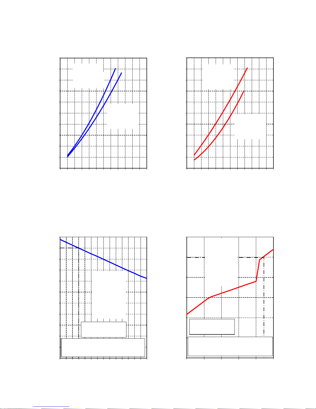
Condition
Indoor: DB20°C
Indoor Air-Flow Volume: High
Pipe Length: 7.5m
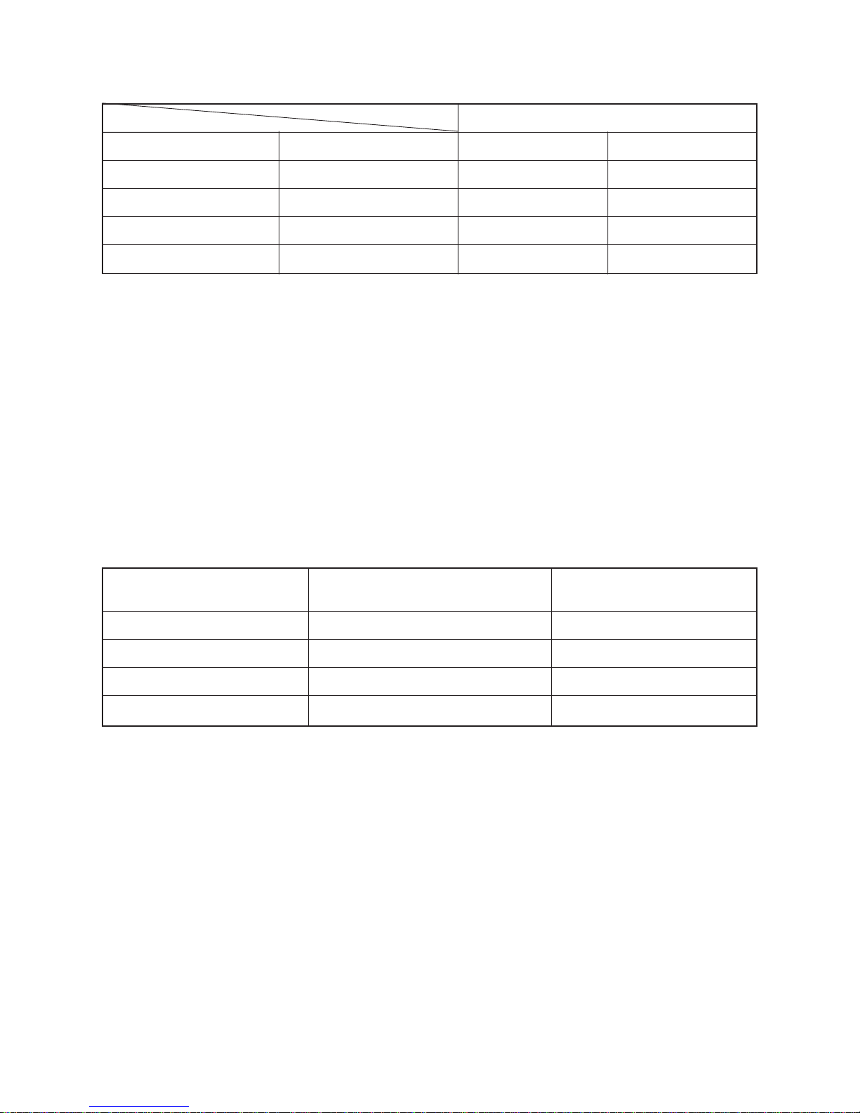
Condition
Indoor: DB27°C/WB19°C
Indoor Air-Flow Volume: High
Pipe Length: 7.5m
Capacity Ratio: 100% =
5.0kW (RAS-18SKV-E, RAS-18SKVR-E, RAS-18SKV2-E,
RAS-18SKV-A, RAS-18SKVR-A, RAS-18SKV-ND)
RAS-22SKV-E
RAS-22SKVR-E
RAS-18SKV-E
RAS-18SKVR-E
2-2. Operation Characteristic Curve
<Cooling> <Heating>
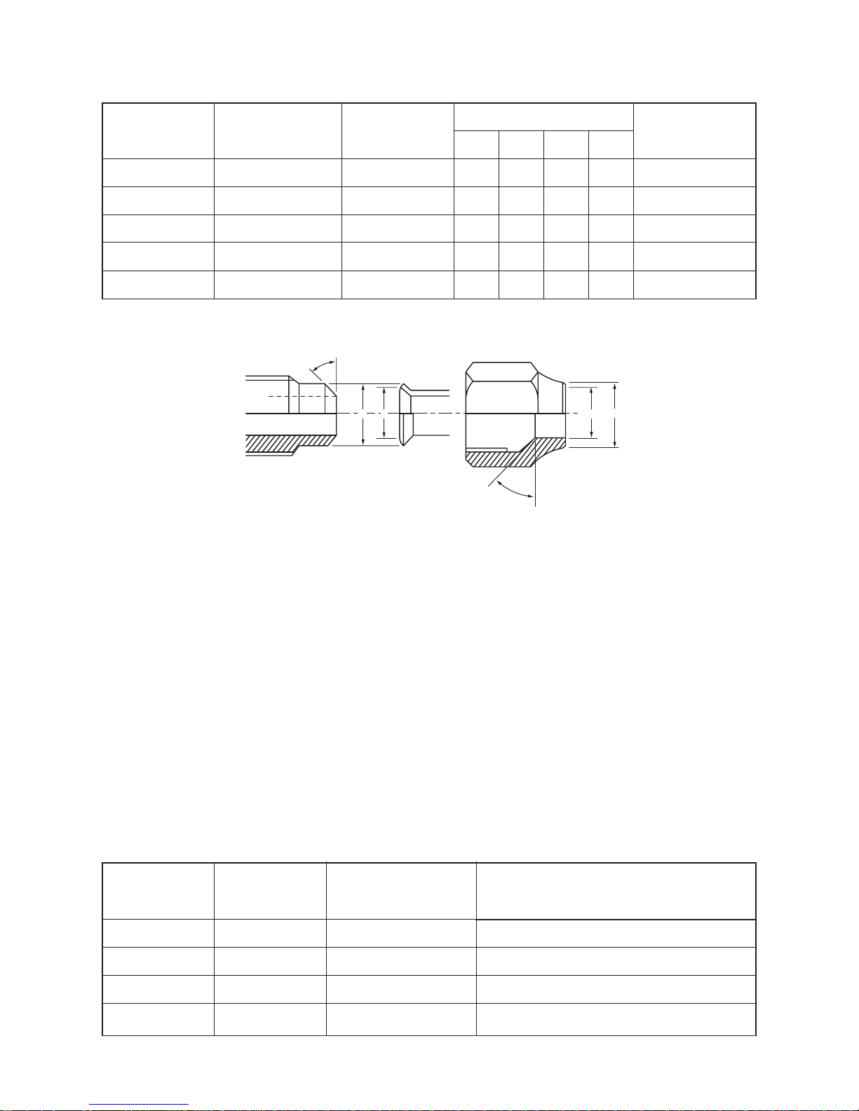
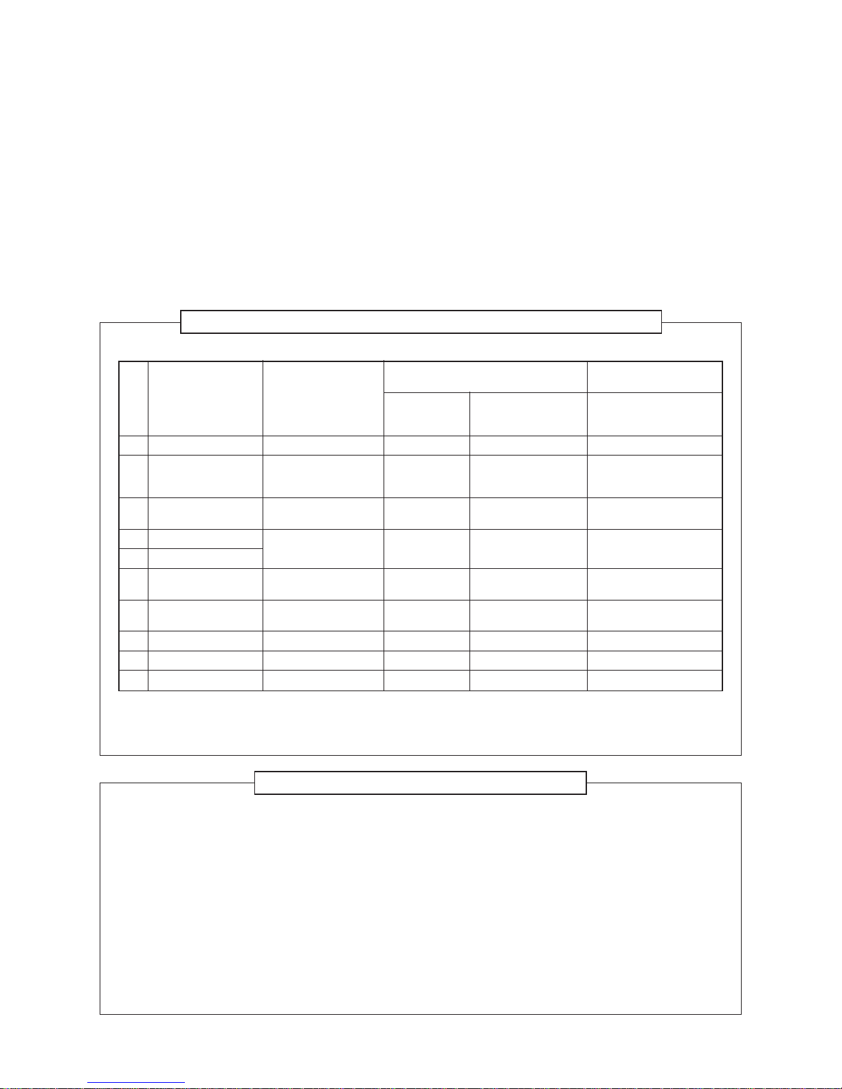
2-3. Capacity Variation Ratio According to Temperature
<Cooling> <Heating>
RAS-22SKV2-E
RAS-22SKV-A
RAS-22SKVR-A
RAS-22SKV-ND
RAS-18SKV2-E
RAS-18SKV-A
RAS-18SKVR-A
RAS-18SKV-ND
RAS-22SKV2-E
RAS-22SKV-A
RAS-22SKVR-A
RAS-22SKV-ND
RAS-22SKV-E
RAS-22SKVR-E
RAS-18SKV2-E
RAS-18SKV-A
RAS-18SKVR-A
RAS-18SKV-ND
RAS-18SKV-E
RAS-18SKVR-E
RAS-18SKV2-E
RAS-18SKV-A
RAS-18SKVR-A
RAS-18SKV-ND
RAS-18SKV-E
RAS-18SKVR-E
RAS-22SKV2-E
RAS-22SKV-A
RAS-22SKVR-A
RAS-22SKV-ND
RAS-22SKV-E
RAS-22SKVR-E
RAS-18SKV2-E
RAS-18SKV-A
RAS-18SKVR-A
RAS-18SKV-ND
RAS-18SKV-E
RAS-18SKVR-E
RAS-22SKV2-E
RAS-22SKV-A
RAS-22SKVR-A
RAS-22SKV-ND
RAS-22SKV-E
RAS-22SKVR-E
6.0kW (RAS-22SKV-E, RAS-22SKVR-E, RAS-22SKV2-E,
RAS-22SKV-A, RAS-22SKVR-A, RAS-22SKV-ND)
7.0kW (RAS-22SKV-E, RAS-22SKVR-E, RAS-22SKV2-E,
RAS-22SKV-A, RAS-22SKVR-A, RAS-22SKV-ND)
Capacity Ratio: 100% =
5.8
kW (RAS-18SKV-E, RAS-18SKVR-E, RAS-18SKV2-E,
RAS-18SKV-A, RAS-18SKVR-A, RAS-18SKV-ND)
FILE NO. SVM-10050

– 12 –
3. REFRIGERANT R410A
This air conditioner adopts the new refrigerant HFC
(R410A) which does not damage the ozone layer.
The working pressure of the new refrigerant R410A
is 1.6 times higher than conventional refrigerant
(R22). The refrigerating oil is also changed in
accordance with change of refrigerant, so be careful
that water, dust, and existing refrigerant or
refrigerating oil are not entered in the refrigerant
cycle of the air conditioner using the new refrigerant
during installation work or servicing time.
The next section describes the precautions for air
conditioner using the new refrigerant. Conforming
to contents of the next section together with the
general cautions included in this manual, perform
the correct and safe work.
3-1. Safety During Installation/Servicing
As R410A’s pressure is about 1.6 times higher than
that of R22, improper installation/servicing may
cause a serious trouble. By using tools and
materials exclusive for R410A, it is necessary to
carry out installation/servicing safely while taking
the following precautions into consideration.
1. Never use refrigerant other than R410A in an air
conditioner which is designed to operate with
R410A.
If other refrigerant than R410A is mixed,
pressure in the refrigeration cycle becomes
abnormally high, and it may cause personal
injury, etc. by a rupture.
2. Confirm the used refrigerant name, and use
tools and materials exclusive for the refrigerant
R410A.
The refrigerant name R410A is indicated on the
visible place of the outdoor unit of the air conditioner using R410A as refrigerant. To prevent
mischarging, the diameter of the service port
differs from that of R22.
3. If a refrigeration gas leakage occurs during
installation/servicing, be sure to ventilate fully.
If the refrigerant gas comes into contact with fire,
a poisonous gas may occur.
4. When installing or removing an air conditioner,
do not allow air or moisture to remain in the
refrigeration cycle. Otherwise, pressure in the
refrigeration cycle may become abnormally high
so that a rupture or personal injury may be
caused.
5. After completion of installation work, check to
make sure that there is no refrigeration gas
leakage.
If the refrigerant gas leaks into the room, coming
into contact with fire in the fan-driven heater,
space heater, etc., a poisonous gas may occur.
6. When an air conditioning system charged with a
large volume of refrigerant is installed in a small
room, it is necessary to exercise care so that,
even when refrigerant leaks, its concentration
does not exceed the marginal level.
If the refrigerant gas leakage occurs and its
concentration exceeds the marginal level, an
oxygen starvation accident may result.
7. Be sure to carry out installation or removal
according to the installation manual.
Improper installation may cause refrigeration
trouble, water leakage, electric shock, fire, etc.
8. Unauthorized modifications to the air conditioner
may be dangerous.
If a breakdown occurs please call a qualified air
conditioner technician or electrician.
Improper repair may result in water leakage,
electric shock and fire, etc.
3-2. Refrigerant Piping Installation
3-2-1. Piping Materials and Joints Used
For the refrigerant piping installation, copper pipes
and joints are mainly used.
Copper pipes and joints suitable for the refrigerant
must be chosen and installed.
Furthermore, it is necessary to use clean copper
pipes and joints whose interior surfaces are less
affected by contaminants.
1. Copper Pipes
It is necessary to use seamless copper pipes
which are made of either copper or copper alloy
and it is desirable that the amount of residual oil
is less than 40 mg/10 m.
Do not use copper pipes having a collapsed,
deformed or discolored portion
(especially on the interior surface).
Otherwise, the expansion valve or capillary tube
may become blocked with contaminants.
As an air conditioner using R410A incurs pressure higher than when using R22, it is necessary
to choose adequate materials.
Thicknesses of copper pipes used with R410A
are as shown in Table 3-2-1.
Never use copper pipes thinner than 0.8 mm
even when it is available on the market.
FILE NO. SVM-10050
– 13 –
Table 3-2-1 Thicknesses of annealed copper pipes
2. Joints
For copper pipes, flare joints or socket joints are used. Prior to use, be sure to remove all contaminants.
a) Flare Joints
Flare joints used to connect the copper pipes cannot be used for pipings whose outer diameter exceeds
20 mm. In such a case, socket joints can be used.
Sizes of flare pipe ends, flare joint ends and flare nuts are as shown in Tables 3-2-3 to 3-2-6 below.
b) Socket Joints
Socket joints are such that they are brazed for connections, and used mainly for thick pipings whose
diameter is larger than 20 mm.
Thicknesses of socket joints are as shown in Table 3-2-2.
Table 3-2-2 Minimum thicknesses of socket joints
3-2-2. Processing of Piping Materials
When performing the refrigerant piping installation, care should be taken to ensure that water or dust does not
enter the pipe interior, that no other oil than lubricating oils used in the installed air-water heat pump is used,
and that refrigerant does not leak.
When using lubricating oils in the piping processing, use such lubricating oils whose water content has been
removed. When stored, be sure to seal the container with an airtight cap or any other cover.
1. Flare processing procedures and precautions
a) Cutting the Pipe
By means of a pipe cutter, slowly cut the pipe so that it is not deformed.
b) Removing Burrs and Chips
If the flared section has chips or burrs, refrigerant leakage may occur.
Carefully remove all burrs and clean the cut surface before installation.
c) Insertion of Flare Nut
Nominal diameter
1/4
3/8
1/2
5/8
Outer diameter (mm)
6.35
9.52
12.70
15.88
Thickness (mm)
R410A R22
0.80 0.80
0.80 0.80
0.80 0.80
1.00 1.00
Nominal diameter
1/4
3/8
1/2
5/8
Reference outer diameter of
copper pipe jointed (mm)
6.35
9.52
12.70
15.88
Minimum joint thickness
(mm)
0.50
0.60
0.70
0.80
FILE NO. SVM-10050

– 14 –
A
ØD
d) Flare Processing
Make certain that a clamp bar and copper
pipe have been cleaned.
By means of the clamp bar, perform the flare
processing correctly.
Use either a flare tool for R410A or conventional flare tool.
Flare processing dimensions differ according
to the type of flare tool.
When using a conventional flare tool, be sure
to secure “dimension A” by using a gauge for
size adjustment.
Fig. 3-2-1 Flare processing dimensions
Table 3-2-3 Dimensions related to flare processing for R410A
Table 3-2-4 Dimensions related to flare processing for R22
Table 3-2-5 Flare and flare nut dimensions for R410A
Nominal
Outer
Thickness
diameter
diameter
(mm)
(mm)
1/4 6.35 0.8
3/8 9.52 0.8
1/2 12.70 0.8
5/8 15.88 1.0
A (mm)
Flare tool for R22
clutch type
0 to 0.5
0 to 0.5
0 to 0.5
0 to 0.5
Conventional flare tool
Clutch type Wing nut type
0.5 to 1.0 1.0 to 1.5
0.5 to 1.0 1.0 to 1.5
0.5 to 1.0 1.5 to 2.0
0.5 to 1.0 1.5 to 2.0
Nominal Outer diameter Thickness
diameter (mm) (mm)
1/4 6.35 0.8
3/8 9.52 0.8
1/2 12.70 0.8
5/8 15.88 1.0
Dimension (mm)
ABCD
9.1 9.2 6.5 13
13.2 13.5 9.7 20
16.0 16.6 12.9 23
19.0 19.7 16.0 25
Flare nut width
(mm)
17
22
26
29
Conventional flare tool
Clutch type Wing nut type
1.0 to 1.5 1.5 to 2.0
1.0 to 1.5 1.5 to 2.0
1.0 to 1.5 2.0 to 2.5
1.0 to 1.5 2.0 to 2.5
Nominal
Outer
Thickness
diameter
diameter
(mm)
(mm)
1/4 6.35 0.8
3/8 9.52 0.8
1/2 12.70 0.8
5/8 15.88 1.0
A (mm)
Flare tool for R410A
clutch type
0 to 0.5
0 to 0.5
0 to 0.5
0 to 0.5
FILE NO. SVM-10050
– 15 –
Table 3-2-6 Flare and flare nut dimensions for R22
Fig. 3-2-2 Relations between flare nut and flare seal surface
2. Flare Connecting Procedures and Precautions
a) Make sure that the flare and union portions do not have any scar or dust, etc.
b) Correctly align the processed flare surface with the union axis.
c) Tighten the flare with designated torque by means of a torque wrench.
The tightening torque for R410A is the same as that for conventional R22.
Incidentally, when the torque is weak, the gas leakage may occur.
When it is strong, the flare nut may crack and may be made non-removable.
When choosing the tightening torque, comply with values designated by manufacturers.
Table 3-2-7 shows reference values.
NOTE :
When applying oil to the flare surface, be sure to use oil designated by the manufacturer.
If any other oil is used, the lubricating oils may deteriorate and cause the compressor to burn out.
Table 3-2-7 Tightening torque of flare for R410A [Reference values]
Nominal Outer diameter Thickness
diameter (mm) (mm)
1/4 6.35 0.8
3/8 9.52 0.8
1/2 12.70 0.8
5/8 15.88 1.0
3/4 19.05 1.0
Dimension (mm)
ABCD
9.0 9.2 6.5 13
13.0 13.5 9.7 20
16.0 16.2 12.9 20
19.0 19.7 16.0 23
23.3 24.0 19.2 34
Flare nut width
(mm)
17
22
24
27
36
43˚ to 45˚
45˚ to 46˚
B A
C
D
Tightening torque of
torque wrenches available on the market
N•m (kgf•cm)
16 (160), 18 (180)
42 (420)
55 (550)
65 (650)
Nominal
Outer
Tightening torque
diameter
diameter
(mm)
N•m (kgf•cm)
1/4 6.35 14 to 18 (140 to 180)
3/8 9.52 33 to 42 (330 to 420)
1/2 12.70 50 to 62 (500 to 620)
5/8 15.88 63 to 77 (630 to 770)
FILE NO. SVM-10050
– 16 –
1. Vacuum pump
Use vacuum pump by attaching
vacuum pump adapter.
2. Torque wrench (For Ø6.35, Ø9.52)
3. Pipe cutter
4. Reamer
5. Pipe bender
6. Level vial
7. Screwdriver (+, –)
8. Spanner or Monkey wrench
9. Hole core drill (Ø65)
10. Hexagon wrench
(Opposite side 4mm)
11. Tape measure
12. Metal saw
Also prepare the following equipments for other installation method and run check.
1. Clamp meter
2. Thermometer
3. Insulation resistance tester
4. Electroscope
3-3. Tools
3-3-1. Required Tools
The service port diameter of packed valve of the outdoor unit in the air-water heat pump using R410A is
changed to prevent mixing of other refrigerant.
To reinforce the pressure-resisting strength, flare processing dimensions and opposite side dimension of flare
nut (For Ø12.7 copper pipe) of the refrigerant piping are lengthened.
The used refrigerating oil is changed, and mixing of oil may cause a trouble such as generation of sludge,
clogging of capillary, etc. Accordingly, the tools to be used are classified into the following three types.
1. Tools exclusive for R410A (Those which cannot be used for conventional refrigerant (R22))
2. Tools exclusive for R410A, but can be also used for conventional refrigerant (R22)
3. Tools commonly used for R410A and for conventional refrigerant (R22)
The table below shows the tools exclusive for R410A and their interchangeability.
Tools exclusive for R410A (The following tools for R410A are required.)
Tools whose specifications are changed for R410A and their interchangeability
(Note 1) When flaring is carried out for R410A using the conventional flare tools, adjustment of projection
margin is necessary. For this adjustment, a copper pipe gauge, etc. are necessary.
(Note 2) Charging cylinder for R410A is being currently developed.
General tools (Conventional tools can be used.)
In addition to the above exclusive tools, the following equipments which serve also for R22 are necessary as the general tools.
No.
1
2
3
4
5
6
7
8
9
10
Used tool
Flare tool
Copper pipe gauge
for adjusting
projection margin
Torque wrench
(For Ø12.7)
Gauge manifold
Charge hose
Vacuum pump
adapter
Electronic balance for
refrigerant charging
Refrigerant cylinder
Leakage detector
Charging cylinder
Usage
Pipe flaring
Flaring by
conventional flare tool
Connection of flare nut
Evacuating, refrigerant
charge, run check, etc.
Vacuum evacuating
Refrigerant charge
Refrigerant charge
Gas leakage check
Refrigerant charge
R410A
air-water heat pump installation
Existence of Whether conventional
new equipment equipment can be
for R410A used
Ye s ∗ (Note 1)
Ye s ∗ (Note 1)
Ye s N o
Ye s N o
Ye s N o
Ye s N o
Ye s N o
Ye s N o
∗ (Note 2) No
Conventional air-water
heat pump installation
Whether new equipment
can be used with
conventional refrigerant
Ye s
∗ (Note 1)
No
No
Ye s
Ye s
No
Ye s
No
FILE NO. SVM-10050
– 17 –
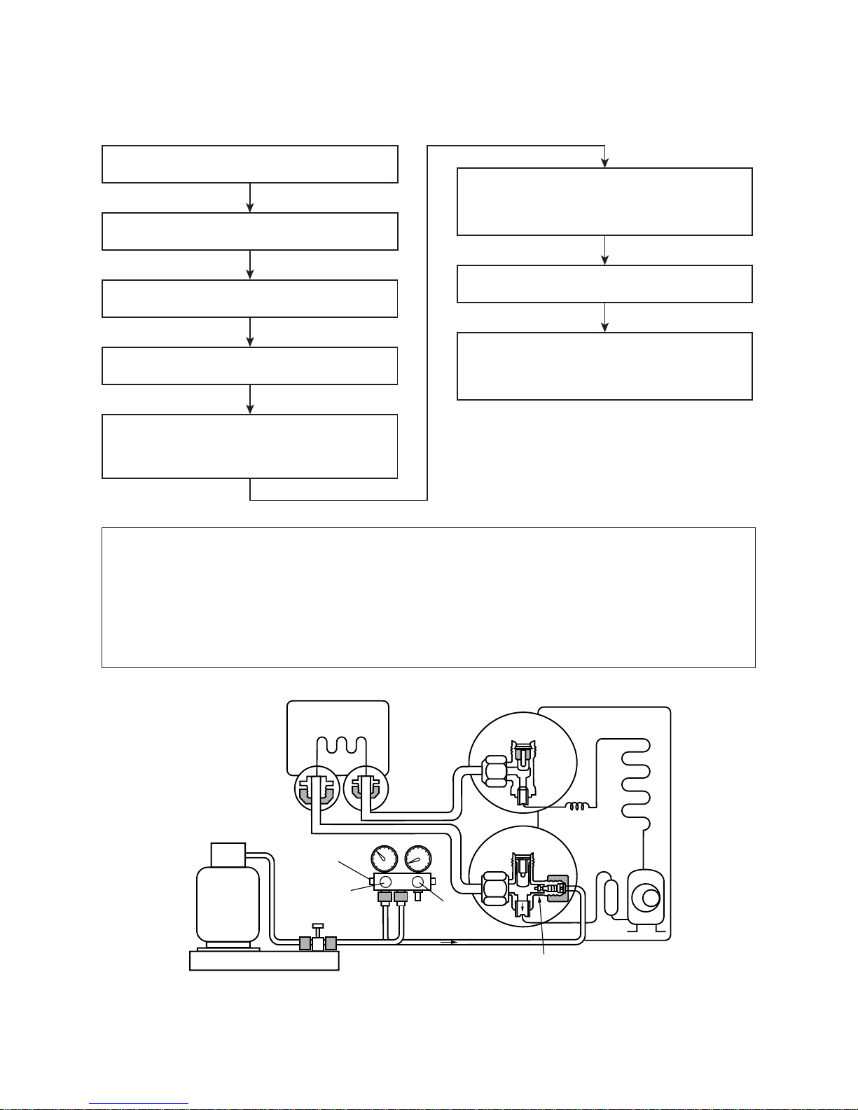
Connect the charge hose to packed valve service
port at the outdoor unit’s gas side.
Recover the refrigerant, and check no refrigerant
remains in the equipment.
(For refrigerant charging, see the figure below.)
Connect the charge hose to the vacuum pump
adapter.
Open fully both packed valves at liquid and gas
sides.
Place the handle of the gauge manifold Low in the
fully opened position, and turn on the vacuum pump’s
power switch. Then, evacuating the refrigerant in the
cycle.
When the compound gauge’s pointer has indicated
–0.1 Mpa (–76 cmHg), place the handle Low in the
fully closed position, and turn off the vacuum pump’s
power switch.
Keep the status as it is for 1 to 2 minutes, and ensure
that the compound gauge’s pointer does not return.
Set the refrigerant cylinder to the electronic balance,
connect the connecting hose to the cylinder and the
connecting port of the electronic balance, and charge
liquid refrigerant.
(Indoor unit)
(Outdoor unit)
Opened
Opened
Refrigerant cylinder
(with siphon)
Check valve
Open/close
valve for charging
Electronic balance for refrigerant charging
Opened
Closed
Service port
3-4. Recharging of Refrigerant
When it is necessary to recharge refrigerant, charge the specified amount of new refrigerant according to the
following steps.
1. Never charge refrigerant exceeding the specified amount.
2. If the specified amount of refrigerant cannot be charged, charge refrigerant bit by bit in COOL mode.
3. Do not carry out additional charging.
When additional charging is carried out if refrigerant leaks, the refrigerant composition changes in the
refrigeration cycle, that is characteristics of the air conditioner changes, refrigerant exceeding the
specified amount is charged, and working pressure in the refrigeration cycle becomes abnormally high
pressure, and may cause a rupture or personal injury.
Fig. 3-4-1 Configuration of refrigerant charging
FILE NO. SVM-10050
– 18 –
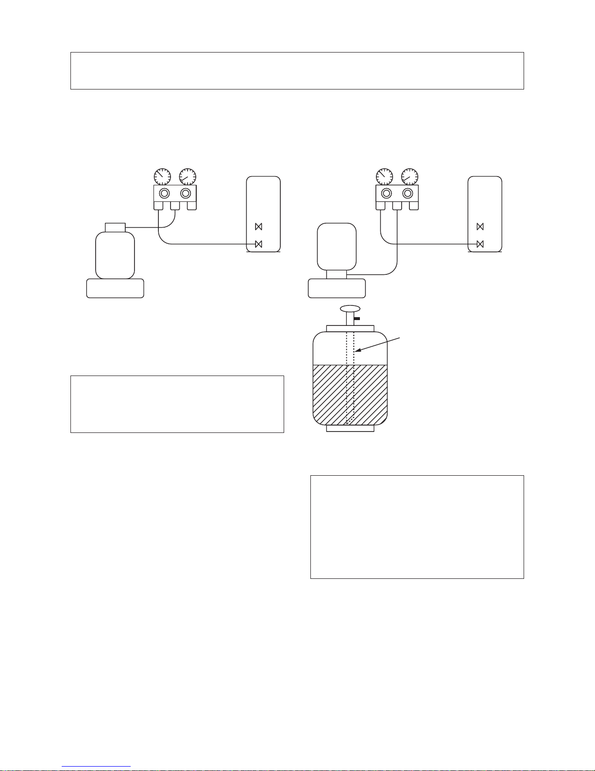
Gauge manifold
[ Cylinder with siphon ] [ Cylinder without siphon ]
OUTDOOR unit
Gauge manifold
OUTDOOR unit
Refrigerant
cylinder
Electronic
balance
Refrigerant
cylinder
Electronic
balance
Siphon
1. Be sure to make setting so that liquid can be charged.
2. When using a cylinder equipped with a siphon, liquid can be charged without turning it upside down.
It is necessary for charging refrigerant under condition of liquid because R410A is mixed type of refrigerant.
Accordingly, when charging refrigerant from the refrigerant cylinder to the equipment, charge it turning the
cylinder upside down if cylinder is not equipped with siphon.
R410A refrigerant is HFC mixed refrigerant.
Therefore, if it is charged with gas, the composition of the charged refrigerant changes and the
characteristics of the equipment varies.
3-5. Brazing of Pipes
3-5-1. Materials for Brazing
1. Silver brazing filler
Silver brazing filler is an alloy mainly composed
of silver and copper. It is used to join iron, copper
or copper alloy, and is relatively expensive
though it excels in solderability.
2. Phosphor bronze brazing filler
Phosphor bronze brazing filler is generally used
to join copper or copper alloy.
3. Low temperature brazing filler
Low temperature brazing filler is generally called
solder, and is an alloy of tin and lead.
Since it is weak in adhesive strength, do not use
it for refrigerant pipes.
1. Phosphor bronze brazing filler tends to react
with sulfur and produce a fragile compound
water solution, which may cause a gas
leakage. Therefore, use any other type of
brazing filler at a hot spring resort, etc., and
coat the surface with a paint.
2. When performing brazing again at time of
servicing, use the same type of brazing filler.
3-5-2. Flux
1. Reason why flux is necessary
• By removing the oxide film and any foreign
matter on the metal surface, it assists the flow
of brazing filler.
• In the brazing process, it prevents the metal
surface from being oxidized.
• By reducing the brazing filler’s surface tension,
the brazing filler adheres better to the treated
metal.
Fig. 3-4-2
FILE NO. SVM-10050
– 19 –
Nitrogen gas
cylinder
Pipe
Flow meter
M
Stop valve
From Nitrogen cylinder
Nitrogen gas
Rubber plug
2. Characteristics required for flux
• Activated temperature of flux coincides with
the brazing temperature.
• Due to a wide effective temperature range, flux
is hard to carbonize.
• It is easy to remove slag after brazing.
• The corrosive action to the treated metal and
brazing filler is minimum.
• It excels in coating performance and is harmless to the human body.
As the flux works in a complicated manner as
described above, it is necessary to select an
adequate type of flux according to the type and
shape of treated metal, type of brazing filler and
brazing method, etc.
3. Types of flux
• Noncorrosive flux
Generally, it is a compound of borax and boric
acid.
It is effective in case where the brazing temperature is higher than 800°C.
• Activated flux
Most of fluxes generally used for silver brazing
are this type.
It features an increased oxide film removing
capability due to the addition of compounds
such as potassium fluoride, potassium chloride
and sodium fluoride to the borax-boric acid
compound.
4. Piping materials for brazing and used
brazing filler/flux
1. Do not enter flux into the refrigeration cycle.
2. When chlorine contained in the flux remains
within the pipe, the lubricating oil deteriorates. Therefore, use a flux which does not
contain chlorine.
3. When adding water to the flux, use water
which does not contain chlorine
(e.g. distilled water or ion-exchange water).
4. Remove the flux after brazing.
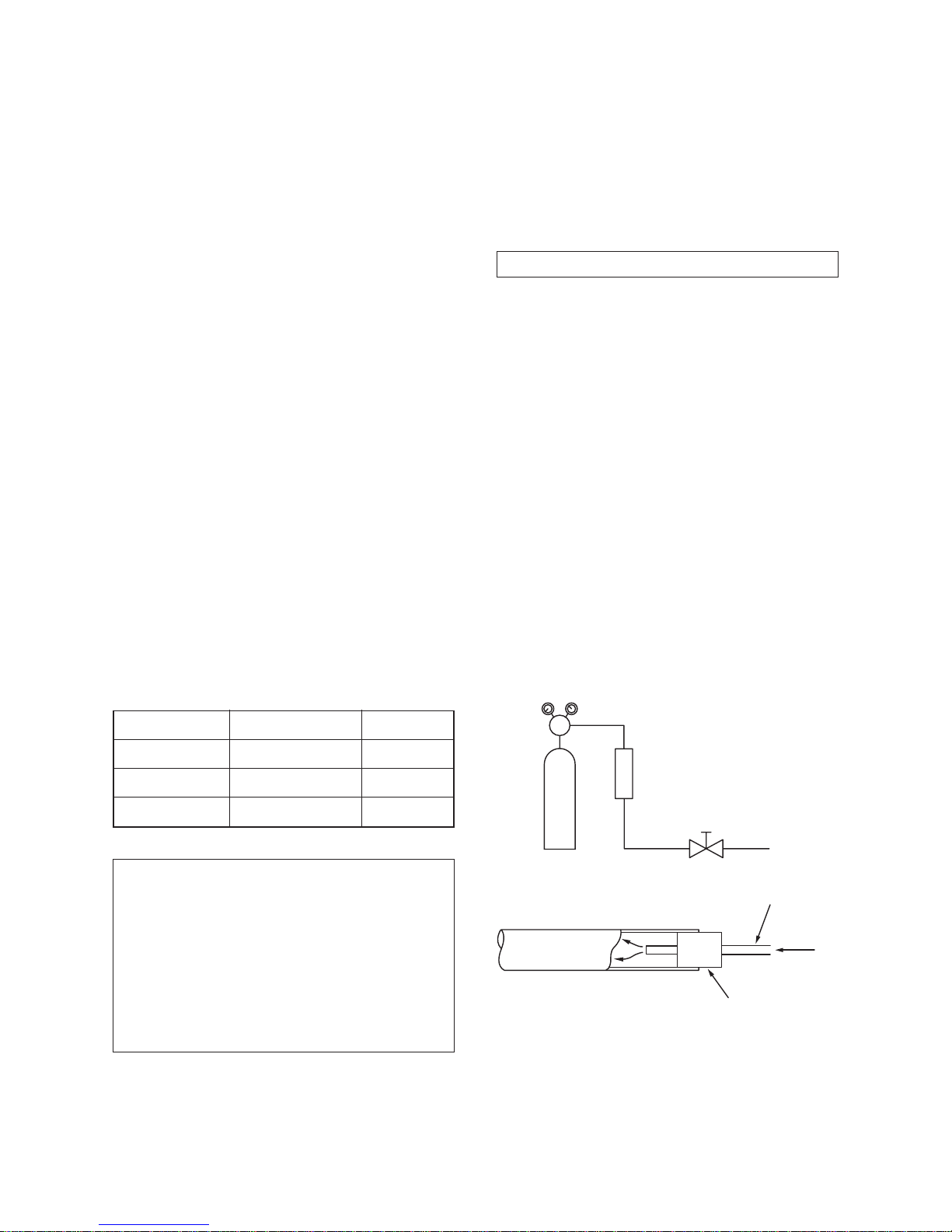
3-5-3. Brazing
As brazing work requires sophisticated techniques,
experiences based upon a theoretical knowledge, it
must be performed by a person qualified.
In order to prevent the oxide film from occurring in
the pipe interior during brazing, it is effective to
proceed with brazing while letting dry Nitrogen gas
(N2) flow.
Never use gas other than Nitrogen gas.
1. Brazing method to prevent oxidation
1) Attach a reducing valve and a flow-meter to
the Nitrogen gas cylinder.
2) Use a copper pipe to direct the piping material, and attach a flow-meter to the cylinder.
3) Apply a seal onto the clearance between the
piping material and inserted copper pipe for
Nitrogen in order to prevent backflow of the
Nitrogen gas.
4) When the Nitrogen gas is flowing, be sure to
keep the piping end open.
5) Adjust the flow rate of Nitrogen gas so that it
is lower than 0.05 m
3
/Hr or 0.02 MPa
(0.2kgf/cm2) by means of the reducing valve.
6) After performing the steps above, keep the
Nitrogen gas flowing until the pipe cools down
to a certain extent (temperature at which
pipes are touchable with hands).
7) Remove the flux completely after brazing.
Fig. 3-5-1
Prevention of oxidation during brazing
Piping material
Copper - Copper
Copper - Iron
Iron - Iron
Used brazing filler
Phosphor copper
Silver
Silver
Used flux
Do not use
Paste flux
Vapor flux
FILE NO. SVM-10050
– 20 –
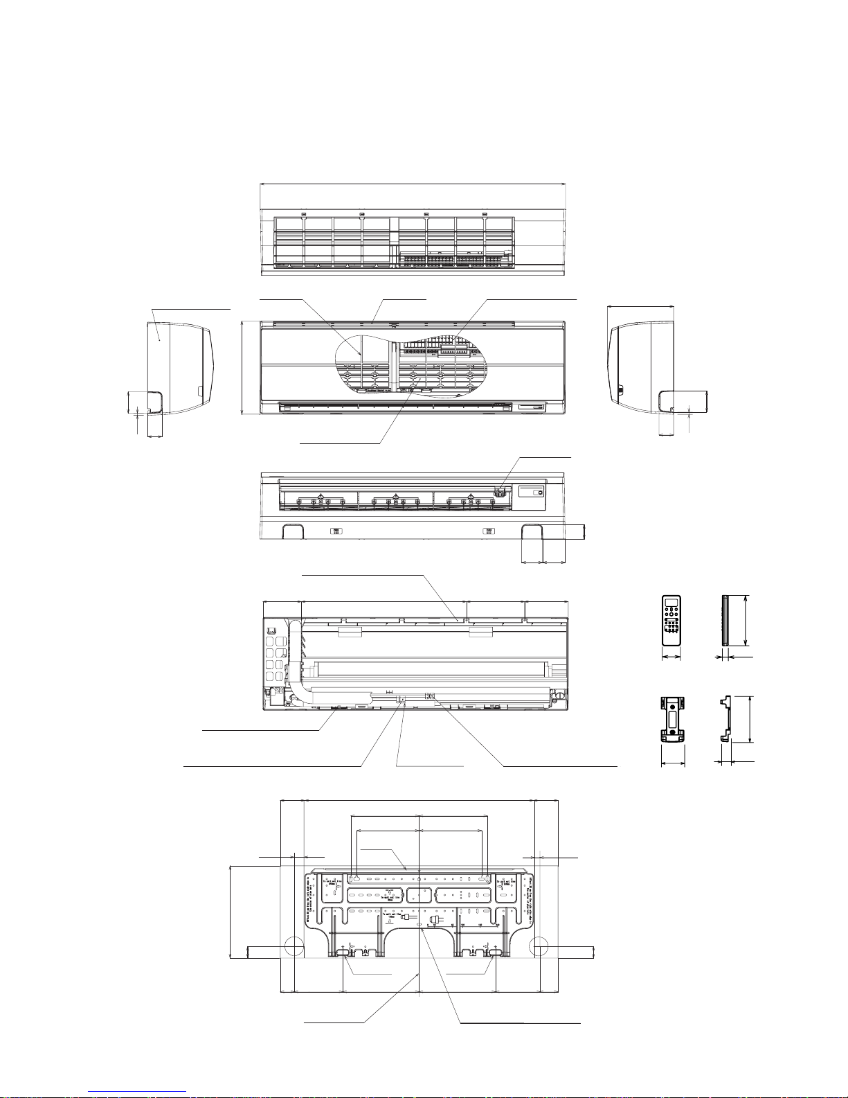
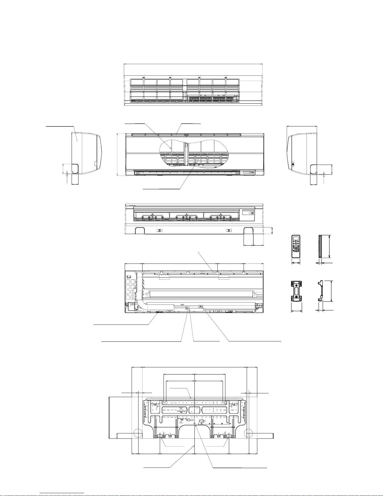
4. CONSTRUCTION VIEWS
4-1. Indoor Unit
1050
50
72
132 568
132
40
40
320
235 235
215 215
47 215.5 262.5 262.5 153.5 109
85
23
786 132
200 150
78
228
73.5
320
50
7
50
73.5
7
Front panel
Air filter
Heat exchanger
Installation plate hanger
Installation plate hanger
Connecting plate (0.39m)
(For 18, 22 series; Flare Ø12.70mm)
Drain hose
(0.5mm)
Hanger
HangerHanger
Center line Instrallation plate outline
Connecting pipe (0.49m)
(Flare Ø6.35mm)
Air ionizer
Air inlet Plasma air purifier
Knock out system Knock out system
FILE NO. SVM-10050
RAS-18SKVR-A, RAS-22SKVR-A
RAS-18SKVR-E, RAS-22SKVR-E
19
157
Wireless remote controller
56
26
125
63
Remote controller holder
– 21 –
1050
50
132 568 200 150
72 78
228
320
132 786
235
47 215.5 262.5 262.5 153.5 109
235
215 215
85
23
132
320
40
40
50
73.5
7
50
73.5
7
Front panel
Air filter
Heat exchanger
Installation plate hanger
Installation plate hanger
Connecting plate (0.39m)
(For 18, 22 series; Flare Ø12.70mm)
Drain hose
(0.5mm)
Connecting pipe (0.49m)
(Flare Ø6.35mm)
Air inlet
Knock out system Knock out system
Hanger
Hanger
Center line Instrallation plate outline
Hanger
19
157
Wireless remote controller
56
26
125
63
Remote controller holder
RAS-18SKV-A, RAS-22SKV-A
RAS-18SKV-E, RAS-22SKV-E
RAS-18SKV2-E, RAS-22SKV2-E
RAS-18SKV-ND, RAS-22SKV-ND
FILE NO. SVM-10050

– 22 –
4-2. Outdoor Unit
320
306
80
Z View
600
A detail Drawing (Back leg)
320
306
Ø
25 Drain outlet
11 x 14
Hole
(For 8 -
10 anchor bolt)
B Detail Drawing (Front leg)
FAN-GUARD
COVER-PV
Electrical part cover
Liquid side
(Flare 6.35)
Ø
(Flare ∅ 12.7)
Gas side
Service port
2 - ∅11 x 14 Long holes (For ∅8- ∅10 anchor bolt)
Installation dimension
Air outlel
100 or more
100 or more
600 or more
600 or more
Air intlel
Ø
Ø
Ø
Ø
6 hole
86
Ø
6 hole
Ø
11x14 hole
R
15
28
A
320
R5.5
36
108 125
50
137
92
5
4
600
320
9060090
275
290
550
Ø
436
Z
R
15
50
36
-
2
320
342
69
2 - R5-5 x 17L Ushape
(For ∅ 8 - ∅10 anchor bolt)
FILE NO. SVM-10050
– 23 –
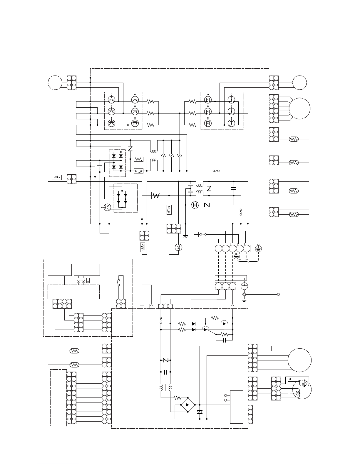
5. WIRING DIAGRAM
5-1. Indoor Unit / Outdoor Unit
P22
Compressor
CM
P. C. Board
MCC-5009
Main P. C. Board
MCC-5045
SKVR-E only
RED
WHI
BLK
P04
P05
P06
P25
YEL
P24
R221
Q200 ~ 205
IGBT
Q300 ~ 305
MOS-FET
CN300
CN700
CN603
CN602
CN601
CN600
Suction pipe
Temp. Sensor
(TS)
Fan Motor
Pulse Motor Valve
FM
1
2
3
1
2
P11
P08
P32
PUR
P33 P30 BLK
CN701 P07
BLK
ORN WHI
P03
P10
P02
P31
Q404
CT
3
BLU
BLU
BLU
1
2
3
1
2
3
BLU
RED
BRW
BLU
BRW
BRW
BRW
4 4
BLU
5 5
BLU
6 6
BLU
7 7
BLU
8 8
BLU
9 9
BLU
CN10
(WHI)
CN61
(WHI)
10 10
1
2
3
1
2
3
4 4
221
1
4433221
1
5 5
6 6
7 7
8 8
9 9
CN21
(WHI)
10 10
BLK
WHI
RED
3
2
1
3
2
1
6
5
4
6
5
4
3 3
2 2
1 1
3
2
1
3
2
1
P23
YEL
P34
P35 L03
L01
Varistor
Varistor
Varistor
Line Filter
Surge
Absorber
F01 Fuse
250V ~, T25A
Fuse, T6.3A
AC 250V
Power Relay
Relay
DB01
DB02
C12 C14
C13
YEL
P21
BRW
P20
R220
R219
PMV
Discharge pipe
Temp. Sensor
(TD)
3
2
1
3
2
1
Condenser pipe
Temp. Sensor
(TE)
212
1
Thermo Sensor (TA)
121
2
CN62
(BLU)
Heat Exchanger Sensor (TC)
121
2
CN42
(WHI)
CN01CN02 CN51
121
2
343
4
Outdoor
Temp. Sensor
(TO)
212
1
R321
R320
R319
P19
P18
Reactor
Reactor
Coil for
4-way Valve
Indoor Terminal Block
Wireless Unit Assembly
MCC-5044
ORN
+ + +
121
2
112
2
11223
3
F03 Fuse
250V ~, T3.15A
NL321
WHI
YEL
YEL
1
2
3
1
2
3
YEL
4
1
2
3
4
4
YEL
5 5
CN22
(WHI)
CN32
(WHI)
CN31
(WHI)
Louver Motor
Fan Motor
1
2
3
1
2
3
4 4
5 5
1
2
3
1
2
3
4 4
BLK
BLK
Sheet
Metal
Micro
SW
WHI
RED
5 5
GRN & YEL
Heat Exchanger
6 6
WHI
11 11 11 11
DC Motor
Power Supply
Circuit
DC5V
DC12V
113
High-voltage
Power Supply
Air Purifier
Electrode
Ion
Electrode
+
F01 Fuse
T3.15A
AC 250V
+
~
~
321
121
2
343
4
N
FILE NO. SVM-10050-1
220-240V~, 50Hz (RAS-18,22SKV-A, 18,22SKVR-A)
Power Supply
220-240V~, 50Hz / 220-230V~, 60Hz
– 24 –
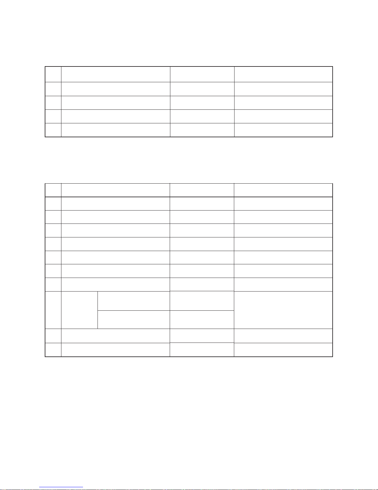
6. SPECIFICATIONS OF ELECTRICAL PARTS
6-1. Indoor Unit
6-2. Outdoor Unit
No.
1
2
3
4
Room temp. sensor (TA-sensor)
Heat exchanger temp. sensor (TC-sensor)
Louver motor
ICF-340-30-2Β
( — )
( — )
MP24Z3T
DC340V, 30W
10kΩ at 25°C
10kΩ at 25°C
Output (Rated) 1W, 16 poles, DC12V
No.
1
2
3
4
5
6
7
8
9
10
Parts name
Reactor
Outdoor fan motor
Suction temp. sensor (TS sensor)
Discharge temp. sensor (TD sensor)
Outside air temp. sensor (TO sensor)
Heat exchanger temp. sensor (TE sensor)
Terminal block (5P)
Compressor
Coil for PMV
Model name
CH-57
ICF-140-43-4R
(Inverter attached)
(Inverter attached)
(Inverter attached)
(Inverter attached)
——
DA130A1F-27F
DA150A1F-20F
CAM-MD12TCTH-2
Rating
L = 10mH, 16A
DC140V, 43W
10kΩ (25°C)
62kΩ (20°C)
10kΩ (25°C)
10kΩ (25°C)
20A, AC250V
3-phases 4-poles 1100W
DC12V
AC220–240V
FILE NO. SVM-10050
Fan motor (for indoor)
Parts name
Type
Specifications
Coil for 4-way valve
STF
22SAV-E2, 22SAV2-E,
18SAV-E2, 18SAV2-E,
18SAV2-A
22SAV2-A

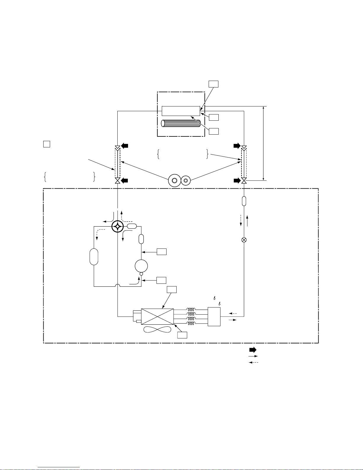
NOTE :
• The maximum pipe length of this air conditioner is 20m. When the pipe length exceeds 15m, the additional
charging of refrigerant, 20g per 1m for the part of pipe exceeded 15m is required. (Max. 100g)
Max. : 20m
Min. : 2m
Chargeless : 15m
Charge : 20g/m
(16 to 20m)
Deoxidized copper pipe
Outer dia. : 12.7mm
Thickness : 0.8mm
NOTE:
Gas leak check position
Refrigerant flow (Cooling)
Refrigerant flow (Heating)
INDOOR UNIT
T1 Temp. measurement
Indoor heat
exchanger
Cross flow fan
Sectional shape
of heat insulator
Allowable height
difference: 10m
Allowable pipe length
P
Pressure measurement
Gauge attaching port
Vacuum pump connecting port
Strainer
Pulse Modulating valve
at liquid side
(CAM-B22YGTF-3)
TD
4-way valve
(STF-0108Z)
Compressor
DA130A1F-27F
Propeller fan
Refrigerant amount: 1.40kg
OUTDOOR UNIT
TC
TA
Outdoor heat
exchanger
Split capillary
2-dia. 1.2 × 80
TE
Muffler
Muffler
Accumulater tank
Deoxidized copper pipe
Outer dia. : 6.35mm
Thickness : 0.8mm
TS
TO
Distributor
FILE NO. SVM-10050
– 25 –
RAS-18SKV-E / RAS-18SAV-E2
RAS-18SKVR-E / RAS-18SAV-E2
RAS-18SKV2-E / RAS-18SAV2-E
RAS-18SKV-A / RAS-18SAV2-A
RAS-18SKVR-A / RAS-18SAV2-A
RAS-18SKV-ND / RAS-18SAV2-E
7. REFRIGERANT CYCLE DIAGRAM
7-1. Refrigerant Cycle Diagram
– 26 –
NOTE :
• The maximum pipe length of this air conditioner is 15m. When the pipe length exceeds 15m, the additional
charging of refrigerant, 20g per 1m for the part of pipe exceeded 15m is required. (Max. 100g)
Strainer
TE
Max. : 20m
Min. : 2m
Chargeless : 15m
Charge : 20g/m
(16 to 20m)
Allowable height
difference: 10m
Allowable pipe length
Pulse Modulating valve
at liquid side
(CAM-B22YGTF-3)
NOTE:
Gas leak check position
Refrigerant flow (Cooling)
Refrigerant flow (Heating)
OUTDOOR UNIT
INDOOR UNIT
T1 Temp. measurement
Indoor heat
exchanger
Cross flow fan
TC
TA
Deoxidized copper pipe
Outer dia. : 12.7mm
Thickness : 0.8mm
Sectional shape
of heat insulator
P
Pressure measurement
Gauge attaching port
Vacuum pump connecting port
Deoxidized copper pipe
Outer dia. : 6.35mm
Thickness : 0.8mm
TD
4-way valve
(STF-
0213Z
)
Compressor
DA150A1F-20F
Muffler
Muffler
Accumulater tank
TS
Propeller fan
Outdoor heat
exchanger
TO
Distributor
RAS-22SKV-E / RAS-22SAV-E2
RAS-22SKVR-E / RAS-22SAV-E2
RAS-22SKV2-E / RAS-22SAV2-E
RAS-22SKV-A / RAS-22SAV2-A
RAS-22SKVR-A / RAS-22SAV2-A
RAS-22SKV-ND / RAS-22SAV2-E
FILE NO. SVM-10050
1 -dia. 2 × 100
2 - 4 -dia. 2 × 66
Split capillary
1
2
3
4
– 27 –
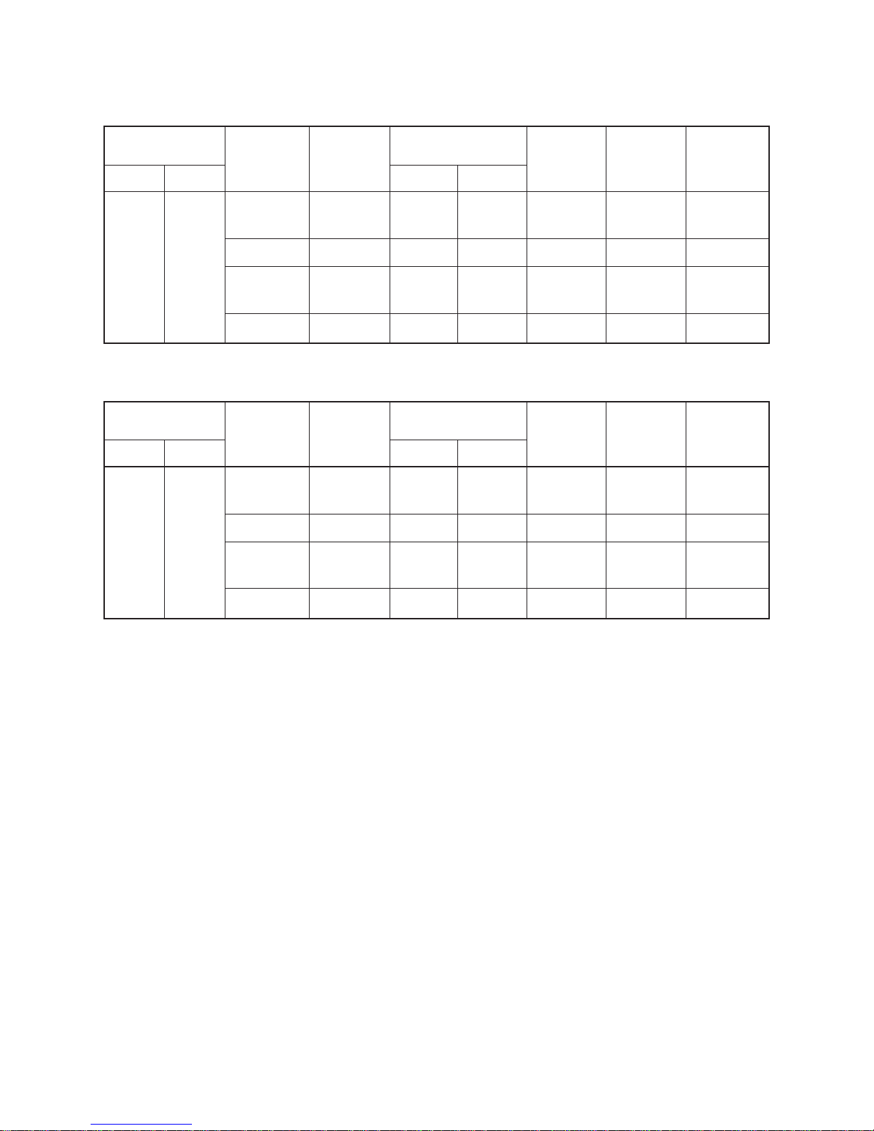
7-2. Operation Data
<Cooling>
Temperature
condition (°C)
Indoor Outdoor
Model name
RAS-
18SKVR-E
Standard
pressure
P (MPa)
0.9 to 1.1
0.9 to 1.1
Heat exchanger
pipe temp.
T1 (°C) T2 (°C)
11 to 13 40 to 42
11 to 13 40 to 42
11 to 13 41 to 43
Indoor
fan mode
High
High
High
Outdoor
fan mode
High
High
High
Compressor
revolution
(rps)
67
67
77
18SKV-E
18SKV2-E
18SKV-A
18SKV-ND
18SKVR-A
22SKV-E
22SKV2-E
22SKV-A
22SKV-ND
22SKVR-E
22SKVR-A
11 to 13 41 to 43 High
0.9 to 1.1
0.9 to 1.1 High 77
2.5 to 2.6
2.5 to 2.6
2.6 to 2.8
2.6 to 2.8
40 to 42 1 to 3
40 to 42 1 to 3
42 to 44 0 to 2
42 to 44 0 to 2 High High
Temperature
condition (°C)
Indoor Outdoor
Model name
RAS-
18SKVR-E
Standard
pressure
P (MPa)
Heat exchanger
pipe temp.
T1 (°C) T2 (°C)
Indoor
fan mode
High
High
High
Outdoor
fan mode
High
High
High
Compressor
revolution
(rps)
79
79
84
18SKV-E
18SKV2-E
18SKV-A
18SKV-ND
18SKVR-A
22SKV-E
22SKV2-E
22SKV-A
22SKV-ND
22SKVR-E
22SKVR-A
84
<Heating>
20/15 7/6
NOTES :
1. Measure surface temperature of heat exchanger pipe around center of heat exchanger path U bent.
(Thermistor themometer)
2. Connecting piping condition : 7.5 m
27/19 35/24
FILE NO. SVM-10050
– 28 –
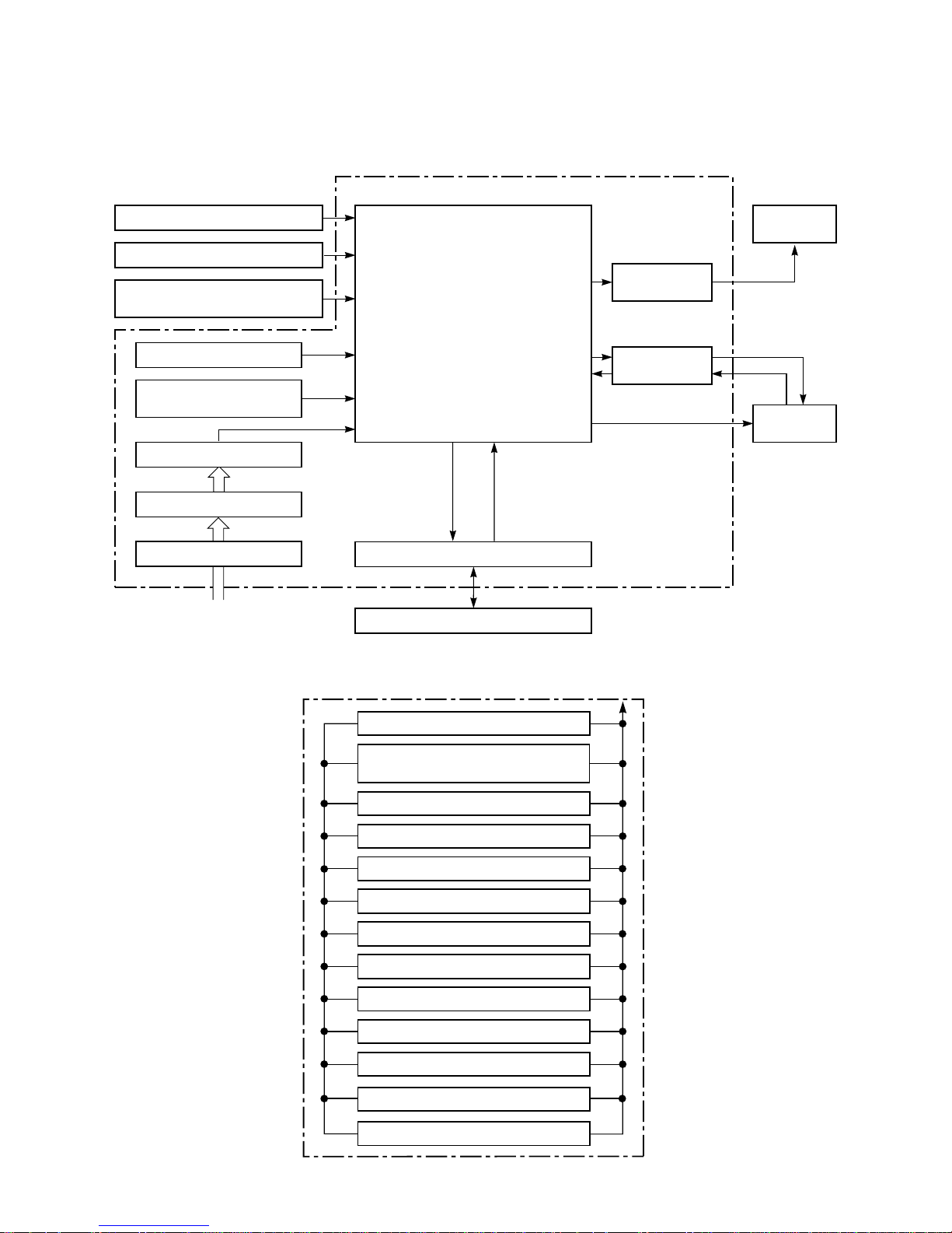
REMOTE CONTROLLER
QUIET
Remote Controller
Infrared Rays, 36.7kHz
Hi-POWER
SLEEP (1, 3, 5, 9 OFF TIMER)
COMFORT SLEEP
ECO
Louver Direction Setting
Louver AUTO Swing
OFF TIMER Setting
ON TIMER Setting
Fan Speed Selection
Thermo. Setting
Operation Mode Selection
AUTO, COOL, DRY, HEAT, FAN
Functions
• Cold draft preventing Function
• 3-minute Delay at Restart
for Compressor
• Fan Motor Starting Control
• Processing
(Temperature Processing)
• Timer
• Serial Signal Communication
• Clean Function
Heat Exchanger Sensor (Tc)
Room Temperature Sensor (Ta)
Infrared Rays Signal Receiver
and Indication
Initializing Circuit
Power Supply Circuit
Converter (D.C circuit)
Noise Filter
Clock Frequency
Oscillator Circuit
M.C.U.
From Outdoor Unit
220-240V ~50Hz
220-230V ~60Hz
Serial Signal Transmitter/Receiver
Serial Signal Communication
(Operation Command and Information)
Indoor Unit Control Unit
Louver Motor
Drive Control
Indoor Fan
Motor Control
Indoor
Fan Motor
Louver
Motor
QUIET
Operation (START/STOP)
8. CONTROL BLOCK DIAGRAM
FILE NO. SVM-10050-1
8-1. Indoor Unit
RAS-18SKV-E, RAS-18SKV2-E, RAS-18SKV-A, RAS-18SKV-ND
RAS-22SKV-E, RAS-22SKV2-E, RAS-22SKV-A, RAS-22SKV-ND
220-240V~, 50Hz (RAS-18,22SKV-A)
– 29 –
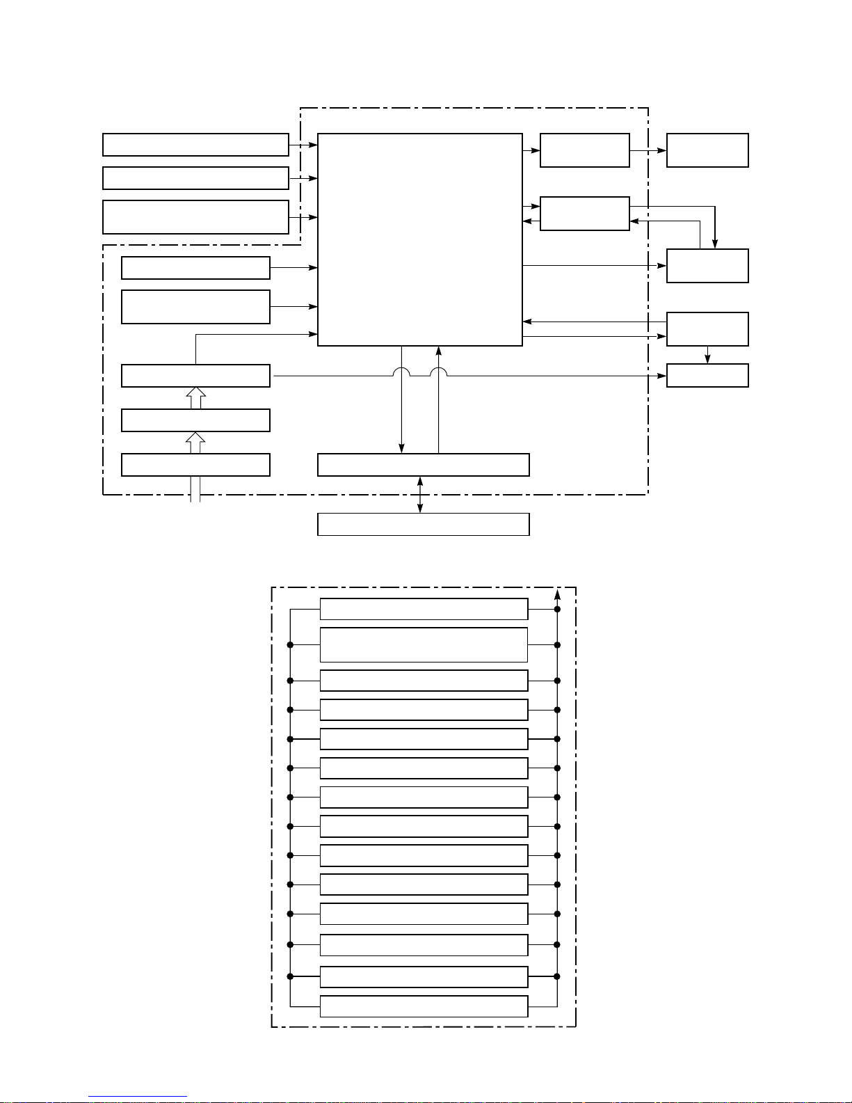
RAS-18SKVR-E, RAS-18SKVR-A, RAS-22SKVR-E, RAS-22SKVR-A
REMOTE CONTROLLER
QUIET
Remote Controller
Infrared Rays, 36.7kHz
Hi-POWER
PURE (Air purifier)
COMFORT SLEEP
ECO
Louver Direction Setting
Louver AUTO Swing
OFF TIMER Setting
ON TIMER Setting
Fan Speed Selection
Thermo. Setting
Operation Mode Selection
AUTO, COOL, DRY, HEAT, FAN
Operation (START/STOP)
Functions
• Cold draft preventing Function
• 3-minute Delay at Restart
for Compressor
• Fan Motor Starting Control
• Processing
(Temperature Processing)
• Timer
• Serial Signal Communication
• Clean Function
Heat Exchanger Sensor (Tc)
Room Temperature Sensor (Ta)
Infrared Rays Signal Receiver
and Indication
Initializing Circuit
Power Supply Circuit
Converter (D.C circuit)
Noise Filter
Clock Frequency
Oscillator Circuit
M.C.U.
From Outdoor Unit
220-240V~, 50Hz
220-230V~, 60Hz
Serial Signal Transmitter/Receiver
Serial Signal Communication
(Operation Command and Information)
Indoor Unit Control Unit
Louver Motor
Drive Control
Indoor Fan
Motor Control
Indoor
Fan Motor
Air purifier
unit
Louver
Motor
Micro Switch
QUIET
SLEEP (1, 3, 5, 9 OFF TIMER)
FILE NO. SVM-10050-1
220-240V~, 50Hz (RAS-18,22SKVR-A)
– 30 –
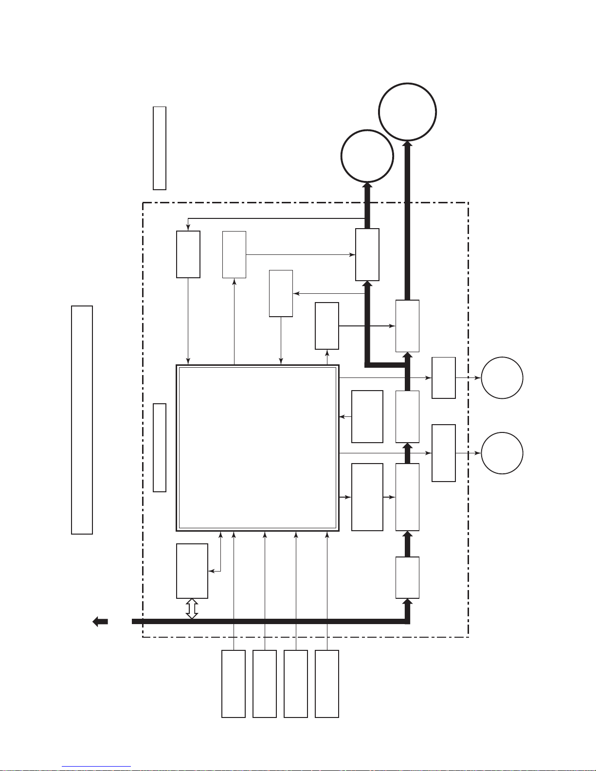
8-2. Outdoor Unit (Inverter Assembly)
Driver circuit
of PMV
Relay
circuit
Clock
frequency
4MHz
Converter
(AC → DC)
Inverter
(DC → AC)
Inverter
(DC → AC)
Input current
sensor
High Power
factor Correction
circuit
MICRO-COMPUTER BLOCK DIAGRAM
For INDOOR UNIT
Heat exchanger
temp.sensor
Suction
temp. sensor
Outdoor air
temp. sensor
Discharge
temp. sensor
Indoor unit
send/receive
circuit
Noise
Filter
MCC5009 (P.C.B)
• PWM synthesis function
• Input current release control
• IGBT over-current detect control
• Outdoor fan control
• High power factor correction control
• Inverter output frequency control
• A/D converter function
• PMV control
• Discharge temp. control
• 4-way valve control
• Signal communication to indoor unit
PMV : Pulse Motor Valve
M.C.U.: Micro Control Unit
Outdoor
Fan motor
Compressor
OUTDOOR UNIT
PMV
4-way
valve
Gate drive
circuit
Current
detect
Current
detect
Gate drive
circuit
M.C.U.
FILE NO. SVM-10050-1
220-240V~, 50Hz
220-230V~, 60Hz
220-240V~, 50Hz (RAS-18,22SAV2-A)
 Loading...