


INSTALLATION MANUAL
AIR CONDITIONER (SPLIT TYPE)
Indoor unit
RAS-10, 13, 16SKV2 Series
Outdoor unit
RAS-10, 13, 16SAV2 Series
Cover 1110251206.indd 1
ENGLISH
ESPAÑOL
FRANÇAIS
ITALIANO
DEUTSCH
PORTUGUÊS
POLSKI
ČESKY HRVATSKI MAGYAR NEDERLANDS
ΕΛΛΗΝΙΚΑ
SVENSKA
SUOMI
NORSK
DANSK
ROMÂNĂ
БЪЛГАРСКИ
EESTI
LATVISKI
SLOVENČINA
SLOVENŠČINA
1110251206
9/18/09 9:57:38 AM

EN CONTENTS |
|
PRECAUTIONS FOR SAFETY.................................................... |
1 |
INSTALLATION DIAGRAM OF INDOOR AND |
|
OUTDOOR UNITS ....................................................................... |
2 |
n Optional Installation Parts ....................................................... |
2 |
INDOOR UNIT.............................................................................. |
3 |
n Installation Place ..................................................................... |
3 |
n Cutting a Hole and Mounting Installation Plate ....................... |
3 |
n Electrical Work ........................................................................ |
3 |
n Wiring Connection ................................................................... |
4 |
n Piping and Drain Hose Installation .......................................... |
4 |
n Indoor Unit Fixing .................................................................... |
5 |
n Drainage.................................................................................. |
5 |
OUTDOOR UNIT.......................................................................... |
5 |
n Installation Place ..................................................................... |
5 |
n Refrigerant Piping Connection ................................................ |
6 |
n Evacuating .............................................................................. |
6 |
n Wiring Connection ................................................................... |
6 |
OTHERS....................................................................................... |
7 |
n Gas Leak Test ......................................................................... |
7 |
n Setting of Remote Control Selector Switch ............................. |
7 |
n Remote Control A-B Selection................................................. |
7 |
n Test Operation ........................................................................ |
7 |
n Auto Restart Setting ............................................................... |
7 |
ES CONTENIDOS |
|
PRECAUCIONES SOBRE SEGURIDAD .................................... |
1 |
DIAGRAMA DE INSTALACIÓN DE LA UNIDAD INTERIOR Y |
|
EXTERIOR ................................................................................... |
2 |
n Piezas de Instalación Opcional .............................................. |
2 |
UNIDAD INTERIOR ..................................................................... |
3 |
n Lugar de Instalación ................................................................ |
3 |
n Corte de un Orificio y Montaje de la Placa de Instalación ...... |
3 |
n Trabajo Eléctrico ..................................................................... |
3 |
n Conexión de Cables ................................................................ |
4 |
n Instalación la Tubería y el Tubo de Desagüe ......................... |
4 |
n Instalación de la Unidad Interior.............................................. |
5 |
n Drenaje ................................................................................... |
5 |
UNIDAD EXTERIOR .................................................................... |
5 |
n Lugar de Instalación ................................................................ |
5 |
n Conexión de la Tubería Refrigerante ...................................... |
6 |
n Evacuación ............................................................................. |
6 |
n Conexión de Cables ................................................................ |
6 |
OTROS......................................................................................... |
7 |
n Comprobación de Fugas ......................................................... |
7 |
n Configuración del interruptor de selección del mando a distancia .. |
7 |
n Mando a distancia A-B Selección............................................ |
7 |
n Prueba de Operación ............................................................. |
7 |
n Ajuste de Reinicio Automático ................................................ |
7 |
FR SOMMAIRE |
|
MESURES DE SÉCURITÉ........................................................... |
1 |
PLAN D’INSTALLATION DES UNITÉS INTÉRIEURE ET |
|
EXTÉRIEURE............................................................................... |
2 |
n Pièces d’Installation en Option ............................................... |
2 |
UNITÉ INTÉRIEURE.................................................................... |
3 |
n Endroit d’Installation ................................................................ |
3 |
n Ouverture du Trou et Montage de la Plaque d’Installation ..... |
3 |
n Travaux Electriques ................................................................ |
3 |
n Connexion des Câbles ............................................................ |
4 |
n Installation de la Conduite et du Tuyau de Purge ................... |
4 |
n Installation de l’Unité Intérieure ............................................... |
5 |
n Drainage ................................................................................. |
5 |
UNITÉ EXTÉRIEURE................................................................... |
5 |
n Endroit d’Installation ................................................................ |
5 |
n Connexion du Tuyau Réfrigérant............................................. |
6 |
n Evacuation .............................................................................. |
6 |
n Connexion des Câbles ............................................................ |
6 |
AUTRES....................................................................................... |
7 |
n Test de Fuite Gaz .................................................................... |
7 |
n Réglage du sélecteur de télécommande................................. |
7 |
n Sélection de télécommande A-B ............................................. |
7 |
n Opération du Test ................................................................... |
7 |
n Réglage de la Remise en Marche Automatique ..................... |
7 |
IT INDICE |
|
PRECAUZIONI PER LA SICUREZZA ......................................... |
1 |
SCHEMA DI INSTALLAZIONE DELL’ UNITÀ INTERNA |
|
E DELL’ UNITÀ ESTERNA.......................................................... |
2 |
n Componenti di Installazione Opzionali ................................... |
2 |
UNITÀ INTERNA ......................................................................... |
3 |
n Luogo per l’Installazione.......................................................... |
3 |
n Apertura di un Foro e Installazione della Lastra di Installazione... |
3 |
n Lavori Elettrici.......................................................................... |
3 |
n Collegamento dei Cavi ............................................................ |
4 |
n Installazione dei Tubi e del Tubo di Scarico ............................ |
4 |
n Installazione dell’Unità Interna ................................................ |
5 |
n Scarico .................................................................................... |
5 |
UNITÀ ESTERNA ........................................................................ |
5 |
n Luogo per l’Installazione.......................................................... |
5 |
n Collegamento dei Tubi del Refrigerante .................................. |
6 |
n Evacuazione ........................................................................... |
6 |
n Collegamento dei Cavi ............................................................ |
6 |
ALTRI ........................................................................................... |
7 |
n Test per Perdite di Gas............................................................ |
7 |
n Impostazione del selettore del telecomando ........................... |
7 |
n Selezione A-B del telecomando .............................................. |
7 |
n Funzionamento di Prova ......................................................... |
7 |
n Impostazione per la Rimessa in Funzione Automatica ........... |
7 |
DE INHALT |
|
SICHERHEITSVORKEHRUNGEN .............................................. |
1 |
EINBAUZEICHNUNGEN FÜR INNENUND |
|
AUSSENGERÄT.......................................................................... |
2 |
n Zusätzlich erhältliche Installationsteile ................................... |
2 |
INNENGERÄT.............................................................................. |
3 |
n Aufstellungsort......................................................................... |
3 |
n Mauerdurchbruch und Befestigung der Montageplatte .......... |
3 |
n Elektrische Anschlüsse ........................................................... |
3 |
n Kabelanschlüsse ..................................................................... |
4 |
n Installation von Leitungen und Kondensatschlauch ................ |
4 |
n Einbau des Innengeräts .......................................................... |
5 |
n Entwässerung ......................................................................... |
5 |
AUSSENGERÄT.......................................................................... |
5 |
n Aufstellungsort......................................................................... |
5 |
n Anschluß der Kühlmittelleitungen............................................ |
6 |
n Entleeren ................................................................................ |
6 |
n Kabelanschlüsse ..................................................................... |
6 |
SONSTIGES................................................................................. |
7 |
n Überprüfung auf Gas-Undichtigkeit ......................................... |
7 |
n Einstellen des Fernbedienungs-Wahlschalters ....................... |
7 |
n Fernbedienung A-B Wahl ........................................................ |
7 |
n Probelauf ................................................................................. |
7 |
n Automatische Wiedereinschaltung .......................................... |
7 |
PT ÍNDICE |
|
PRECAUÇÕES RELATIVAS A SEGURANÇA............................ |
1 |
ESQUEMA DE INSTALAÇÃO DAS UNIDADES INTERIOR |
|
E EXTERIOR................................................................................ |
2 |
n Peças de Instalação Opcionais ............................................... |
2 |
UNIDADE INTERIOR................................................................... |
3 |
n Local de Instalação ................................................................. |
3 |
n Cortar um Orifício e Montar a Placa de Instalação ................. |
3 |
n Trabalhos de Electricidade...................................................... |
3 |
n Ligações Eléctricas ................................................................. |
4 |
n Instalação da Tubagem e do Tubo Flexível de Dreno............. |
4 |
n Colocação da Unidade Interior................................................ |
5 |
n Drenagem................................................................................ |
5 |
UNIDADE EXTERIOR.................................................................. |
5 |
n Local de Instalação ................................................................. |
5 |
n Ligação das Condutas de Refrigeração .................................. |
6 |
n Purga de Ar ............................................................................. |
6 |
n Ligações Eléctricas ................................................................. |
6 |
OUTROS ...................................................................................... |
7 |
n Teste de Fugas de Gás ........................................................... |
7 |
n Definição do interruptor do telecomando ................................ |
7 |
n Selecção A-B do telecomando ................................................ |
7 |
n Execução do Teste .................................................................. |
7 |
n Definindo de Reiniciação Automática...................................... |
7 |
PL SPIS TREŚCI |
|
ZASADY BEZPIECZEŃSTWA..................................................... |
1 |
SCHEMAT INSTALACYJNY URZĄDZENIA WEWNĘTRZNEGO |
|
I ZEWNĘTRZNEGO..................................................................... |
2 |
n Dodatkowe Części Instalacyjne............................................... |
2 |
URZĄDZENIE WEWNĘTRZNE ................................................... |
3 |
n Miejsce Instalacji ..................................................................... |
3 |
n Wycinanie Otworu oraz Montaż Płyty Instalacyjnej................. |
3 |
n Prace Elektryczne ................................................................... |
3 |
n Podłączenie Okablowania ....................................................... |
4 |
n Montaż Instalacji Rurowej i Węża do Odprowadzania Cieczy .. |
4 |
n Mocowanie Urządzenia Wewnętrznego .................................. |
5 |
n Odprowadzanie Cieczy ........................................................... |
5 |
URZĄDZENIE ZEWNĘTRZNE .................................................... |
5 |
n Miejsce Instalacji ..................................................................... |
5 |
n Łączenie Instalacji Rurowej Czynnika Chłodniczego .............. |
6 |
n Usuwanie Powietrza................................................................ |
6 |
n Podłączenie Okablowania ....................................................... |
6 |
INNE............................................................................................. |
7 |
n Próba Gazoszczelności........................................................... |
7 |
n Ustawianie przełącznika wyboru pilota.................................... |
7 |
n Ustawienia przełącznika A-B wyboru pilota............................. |
7 |
n Próba Działania ....................................................................... |
7 |
n Włączanie Funkcji Automatycznego Wznawiania Pracy (Auto Restart) .. |
7 |
CZ OBSAH |
|
BEZPEČNOSTNÍ OPATŘENÍ ...................................................... |
1 |
SCHÉMA INSTALACE VNITŘNÍ A VENKOVNÍ JEDNOTKY...... |
2 |
n Volitelné Doplňky pro Instalaci ................................................ |
2 |
VNITŘNÍ JEDNOTKA .................................................................. |
3 |
n Místo Instalace ........................................................................ |
3 |
n Vyvrtání Otvoru a Montáž Instalační Desky ............................ |
3 |
n Elektrické Práce ...................................................................... |
3 |
n Zapojení Vodičů....................................................................... |
4 |
n Montáž Trubek a Vypouštěcí Hadice....................................... |
4 |
n Montáž Vnitřní Jednotky.......................................................... |
5 |
n Odvod Vody............................................................................. |
5 |
VENKOVNÍ JEDNOTKA.............................................................. |
5 |
n Místo Instalace ........................................................................ |
5 |
n Spojování Chladivového Potrubí ............................................. |
6 |
n Vyčerpávání Vzduchu.............................................................. |
6 |
n Zapojení Vodičů....................................................................... |
6 |
OSTATNĺ...................................................................................... |
7 |
n Zkouška Úniku Plynu............................................................... |
7 |
n Nastavení přepínače dálkového ovládání ............................... |
7 |
n Volba A-B na dálkovém ovládání............................................. |
7 |
n Zkušební Provoz ..................................................................... |
7 |
n Nastavení Automatického Znovuspuštění ............................... |
7 |
CR SADRŽAJ |
|
MJERE SIGURNOSTI.................................................................. |
1 |
SHEMA UGRADNJE UNUTARNJIH I VANJSKIH JEDINICA..... |
2 |
n Dodatni Dijelovi za Ugradnju Prema Izboru ........................... |
2 |
UNUTARNJA JEDINICA.............................................................. |
3 |
n Mjesto Ugradnje ...................................................................... |
3 |
n Izrezivanje Rupe i Postavljanje Ploče za Ugradnju ................. |
3 |
n Električni Radovi...................................................................... |
3 |
n Žičana Veza............................................................................. |
4 |
n Ugradnja Cijevi i Crijeva za Pražnjenje ................................... |
4 |
n Učvršćivanje Unutarnje Jedinice ............................................. |
5 |
n Ispust....................................................................................... |
5 |
VANJSKA JEDINICA................................................................... |
5 |
n Mjesto Ugradnje ...................................................................... |
5 |
n Sklop Cijevi Rashladnog Sredstva .......................................... |
6 |
n Pražnjenje ............................................................................... |
6 |
n Žičana Veza............................................................................. |
6 |
OSTALO....................................................................................... |
7 |
n Proba Isticanja Plina................................................................ |
7 |
n Položaji prekidača za odabir daljinskog upravljača ................. |
7 |
n Odabir A-B pomoću daljinskog upravljača............................... |
7 |
n Probni Rad .............................................................................. |
7 |
n Postava za Automatsko Ponovno Pokretanje ......................... |
7 |
HU TARTALOMJEGYZÉK |
|
BIZTONSÁGI ELŐÍRÁSOK......................................................... |
1 |
BELTÉRI ÉS KÜLTÉRI EGYSÉGEK ÜZEMBE HELYEZÉSE..... |
2 |
n Külön Rendelhető Alkatrészek ................................................ |
2 |
BELTÉRI EGYSÉG ...................................................................... |
3 |
n A Felszerelés Helye................................................................. |
3 |
n Lyuk Kivágása és a Felszerelése............................................ |
3 |
n Elektromos Munka................................................................... |
3 |
n Kábelezés................................................................................ |
4 |
n A Csövek és a Kondenzvíztömlő Felszerelése ....................... |
4 |
n A Beltéri Egység Rögzítése..................................................... |
5 |
n Vízelvezetés ............................................................................ |
5 |
KÜLTÉRI EGYSÉG...................................................................... |
5 |
n A Felszerelés Helye................................................................. |
5 |
n Hűtőközegcső-csatlakozások.................................................. |
6 |
n Légtelenítés ............................................................................ |
6 |
n Kábelezés................................................................................ |
6 |
EGYEBEK.................................................................................... |
7 |
n Tömítettségvizsgálat ............................................................... |
7 |
n A távirányító kiválasztó kapcsolójának beállítása.................... |
7 |
n A távirányítón az A-B állás kiválasztása .................................. |
7 |
n Tesztüzem ............................................................................... |
7 |
n Automatikus Újraindítás Beállítás............................................ |
7 |
Cover 1110251206.indd 2
NL INHOUDSOPGAVE |
|
VEILIGHEIDSVOORZORGEN..................................................... |
1 |
INSTALLATIESCHEMA VOOR BINNENEN |
|
BUITENMODULES ...................................................................... |
2 |
n Optionele Onderdelen ............................................................. |
2 |
BINNENMODULE ........................................................................ |
3 |
n Installatieplaats........................................................................ |
3 |
n Gat Boren en Montageplaat Bevestigen ................................. |
3 |
n Elektriciteit ............................................................................... |
3 |
n Bedrading ................................................................................ |
4 |
n Leidingen en Afvoerslang Installeren ...................................... |
4 |
n Binnenmodule Bevestigen....................................................... |
5 |
n Afvoer ...................................................................................... |
5 |
BUITENMODULE......................................................................... |
5 |
n Installatieplaats........................................................................ |
5 |
n Koelleidingsaansluiting............................................................ |
6 |
n Afvoeren ................................................................................. |
6 |
n Bedrading ................................................................................ |
6 |
OVERIGE ..................................................................................... |
7 |
n Gaslektest ............................................................................... |
7 |
n De keuzeschakelaar van de afstandsbediening instellen........ |
7 |
n Afstandsbediening keuze A-B ................................................. |
7 |
n Testwerking ............................................................................. |
7 |
n Automatische Herstart Instellen .............................................. |
7 |
GR ΠΕΡΙΕXOΜΕΝΑ
ΠΡOΦΥΛΑ ΕΙΣ ΑΣΦΑΛΕΙΑΣ....................................................... |
1 |
∆ΙΆΓΡΑΜΜΑ ΕΓΚΑΤΆΣΤΑΣΗΣ ΤΗΣ ΕΣΩΤΕΡΙΚΉΣ ΚΑΙ |
|
Ε ΩΤΕΡΙΚΉΣ ΜOΝΆ∆ΑΣ .......................................................... |
2 |
n Πρ αιρετικά E αρτήµατα Eγκατάστασης........................... |
2 |
ΕΣΩΤΕΡΙΚΉ ΜOΝΆ∆Α............................................................... |
3 |
n Σηµεί Eγκατάστασης .......................................................... |
3 |
n Κ ψιµ Τρύπας και Τ π θέτηση Πλάτης Εγκατάστασης... |
3 |
n Ηλεκτρικές Εργασίες............................................................ |
3 |
n Σύνδεση Καλωδίωσης........................................................... |
4 |
n Εγκατάσταση Σωλήνωσης και Eύκαµπτ υ Σωλήνα Aπ στράγγισης.. |
4 |
n Στερέωση Εσωτερικής Μoνάδας......................................... |
5 |
n Απoστράγγιση........................................................................ |
5 |
Ε ΩΤΕΡΙΚΉ ΜOΝΆ∆Α............................................................... |
5 |
n Σηµείo Εγκατάστασης .......................................................... |
5 |
n Σύνδεση Ψυκτικών Σωληνώσεων........................................ |
6 |
n Εκκένωση............................................................................... |
6 |
n Σύνδεση Καλωδίωσης........................................................... |
6 |
ΛOΙΠΑ .......................................................................................... |
7 |
n Έλεγ.oς ∆ιαρρoής Αερίoυ................................................... |
7 |
n Ρύθµιση τoυ διακ πτη επιλoγής τηλε.ειριστηρίoυ .......... |
7 |
n Επιλ γή Α-Β τoυ τηλε.ειριστηρίoυ..................................... |
7 |
n ∆oκιµή Λειτoυργίας .............................................................. |
7 |
n Auto Restart Ρύθµιση ........................................................... |
7 |
9/18/09 9:57:40 AM

SV INNEHÅLLSLFÖRTECKNING |
|
SÄKERHETSANVISNINGAR ...................................................... |
1 |
INSTALLATIONSSCHEMA FÖR INOMHUSOCH |
|
UTOMHUSENHETEN .................................................................. |
2 |
n Valfria installationskomponenter.............................................. |
2 |
INOMHUSENHETEN ................................................................... |
3 |
n Plats för montering .................................................................. |
3 |
n Skära ut ett hål och fästa monteringsplåten ............................ |
3 |
n Elarbeten ................................................................................. |
3 |
n Ledningsdragningar................................................................. |
4 |
n Installera rör och dräneringsslang ........................................... |
4 |
n Fästa inomhusenheten............................................................ |
5 |
n Dränering................................................................................. |
5 |
UTOMHUSENHETEN .................................................................. |
5 |
n Plats för montering .................................................................. |
5 |
n Anslutning av köldmedierör ..................................................... |
6 |
n Vakuumsugning....................................................................... |
6 |
n Ledningsdragningar................................................................. |
6 |
ÖVRIGT........................................................................................ |
7 |
n Kontrollera gasläckor............................................................... |
7 |
n Inställning av fjärrkontrollens omkopplare ............................... |
7 |
n Fjärrkontroll A-B Val................................................................. |
7 |
n Testkörning .............................................................................. |
7 |
n Inställning av omstart .............................................................. |
7 |
FI SISÄLLYSLUETTELO |
|
VAROTOIMENPITEET................................................................. |
1 |
SISÄJA ULKOYKSIKKÖJEN ASENNUSKAAVIO.................... |
2 |
n Lisävarusteena saatavat asennusosat .................................... |
2 |
SISÄYKSIKKÖ............................................................................. |
3 |
n Asennuspaikka ........................................................................ |
3 |
n Aukon tekeminen ja asennuslevyn kiinnittäminen................... |
3 |
n Sähkötyöt ................................................................................ |
3 |
n Johtoliitännät ........................................................................... |
4 |
n Putkiston ja tyhjennysletkun asentaminen .............................. |
4 |
n Sisäyksikön kiinnittäminen ...................................................... |
5 |
n Vedenpoisto............................................................................. |
5 |
ULKOYKSIKKÖ........................................................................... |
5 |
n Asennuspaikka ........................................................................ |
5 |
n Kylmänesteputkien liittäminen................................................. |
6 |
n Tyhjentäminen ......................................................................... |
6 |
n Johtoliitännät ........................................................................... |
6 |
MUUT ........................................................................................... |
7 |
n Kaasuvuototesti....................................................................... |
7 |
n Kauko-ohjaimen valitsinkytkimen säätäminen......................... |
7 |
n Kauko-ohjaimen A-B valinta .................................................... |
7 |
n Koekäyttö ................................................................................ |
7 |
n Automaattisen uudelleenkäynnistyksen asettaminen.............. |
7 |
NO INNHOLDSFORTEGNELSE |
|
SIKKERHETSREGLER ............................................................... |
1 |
KOBLINGSSKJEMA FOR INNEOG UTENDØRSENHETEN ... |
2 |
n Ekstrautstyr ............................................................................. |
2 |
INNENHETEN .............................................................................. |
3 |
n Plassering................................................................................ |
3 |
n Lage et Hull og Montere Montasjeplaten................................. |
3 |
n Elektrisk Arbeid........................................................................ |
3 |
n Tilkobling av Ledninger............................................................ |
4 |
n Installasjon av Rør og Avløpsslange ....................................... |
4 |
n Plassering av Innendørsenheten............................................. |
5 |
n Avløp ....................................................................................... |
5 |
UTENDØRSENHET ..................................................................... |
5 |
n Montasjested ........................................................................... |
5 |
n Tilkobling av Kjølerørene......................................................... |
6 |
n Evakuering .............................................................................. |
6 |
n Tilkobling av Ledninger............................................................ |
6 |
ANNET ......................................................................................... |
7 |
n Gasslekkasjetest ..................................................................... |
7 |
n Stille fjernkontrollbryteren........................................................ |
7 |
n Fjernkontroll A-B valg .............................................................. |
7 |
n Testdrift.................................................................................... |
7 |
n Innstillinger for Auto Restart .................................................... |
7 |
DK INDHOLD |
|
SIKKERHEDSFORHOLDSREGLER........................................... |
1 |
INSTALLATIONSDIAGRAM FOR INDDØRS OG UDENDØRS |
|
ENHED......................................................................................... |
2 |
n Valgfrie installationsdele.......................................................... |
2 |
INDENDØRS ENHED .................................................................. |
3 |
n Installationssted....................................................................... |
3 |
n Skæring af et hul og montering af installationspladen............. |
3 |
n Elektrisk arbejde...................................................................... |
3 |
n Tilslutning af kabel................................................................... |
4 |
n Installation af rør og drænrør................................................... |
4 |
n Fastsætning af den indendørs enhed...................................... |
5 |
n Dræning................................................................................... |
5 |
UDENDØRS ENHED ................................................................... |
5 |
n Installationssted....................................................................... |
5 |
n Kølerørsforbindelsen ............................................................... |
6 |
n Evakuering .............................................................................. |
6 |
n Tilslutning af kabel................................................................... |
6 |
ANDET ......................................................................................... |
7 |
n Gaslækagekontrol ................................................................... |
7 |
n Indstilling af fjernbetjeningskontakten ..................................... |
7 |
n Valg af fjernbetjening A-B ........................................................ |
7 |
n Testdrift ................................................................................... |
7 |
n Auto-omstartsindstilling ........................................................... |
7 |
RO CONŢINUT |
|
MĂSURI DE SIGURANŢĂ........................................................... |
1 |
SCHEMA DE INSTALARE A UNITĂŢILOR INTERIOARĂ ŞI |
|
EXTERIOARĂ.............................................................................. |
2 |
n Piese de instalare opţionale .................................................... |
2 |
UNITATE INTERIOARĂ............................................................... |
3 |
n Locul de instalare .................................................................... |
3 |
n Executarea unei găuri şi montarea plăcii de instalare............. |
3 |
n Lucrările electrice .................................................................... |
3 |
n Racordarea cablurilor .............................................................. |
4 |
n Instalarea ţevilor şi a furtunului de evacuare........................... |
4 |
n Fixarea unităţii interioare ......................................................... |
5 |
n Evacuarea ............................................................................... |
5 |
UNITATEA EXTERIOARĂ ........................................................... |
5 |
n Locul de instalare .................................................................... |
5 |
n Racordarea ţevilor de lichid refrigerent ................................... |
6 |
n Evacuarea .............................................................................. |
6 |
n Racordarea cablurilor .............................................................. |
6 |
ALTELE........................................................................................ |
7 |
n Verifi carea scurgerilor de gaz................................................. |
7 |
n Setarea butonului selector al telecomenzii.............................. |
7 |
n Alegerea telecomenzii A-B ...................................................... |
7 |
n Verificarea funcţionării ............................................................. |
7 |
n Setarea Auto Restart (repornirea automată) ........................... |
7 |
BG СЪДЪРЖАНИЕ |
|
ПРЕДПАЗНИ МЕРКИ ЗА БЕЗОПАСНОСТ .............................. |
1 |
ДИАГРАМА ЗА ИНСТАЛИРАНЕ НА ВЪТРЕШНИЯТ И |
|
ВЪНШНИЯТ МОДУЛ ................................................................. |
2 |
n Допълнителни елементи за монтаж.................................... |
2 |
ВЪТРЕШЕН МОДУЛ.................................................................. |
3 |
n Място за монтаж ................................................................... |
3 |
n Пробиване на отвор и монтиране на монтажната планка .. |
3 |
n Работа по електрическата система..................................... |
3 |
n Свързване на кабелите........................................................ |
4 |
n Инсталиране на тръбите и гъвкавата дренажна тръба .... |
4 |
n Фиксиране на вътрешния модул.......................................... |
5 |
n Дренаж ................................................................................... |
5 |
ВЪНШЕН МОДУЛ ...................................................................... |
5 |
n Място за монтаж ................................................................... |
5 |
n Свързване на тръбите за хладилния агент ........................ |
6 |
n Създаване на вакуум ........................................................... |
6 |
n Свързване на кабелите........................................................ |
6 |
ДРУГИ.......................................................................................... |
7 |
n Тест за наличие на газови течове........................................ |
7 |
n Настройване на избиращия превключвател за |
|
дистанционно управление.................................................... |
7 |
n Избиране на настройки „А” или „В” на дистанционното |
|
управление............................................................................. |
7 |
n Тестов режим ......................................................................... |
7 |
n Настройка за автоматично рестартиране ......................... |
7 |
EE SISUKORD |
|
OHUTUSABINÕUD...................................................................... |
1 |
SISEJA VÄLISSEADMETE PAIGALDUSSKEEM .................... |
2 |
n Valikulised paigaldusdetailid.................................................... |
2 |
SISESEADE................................................................................. |
3 |
n Paigalduskoht.......................................................................... |
3 |
n Augu tegemine ja paigaldusplaadi monteerimine.................... |
3 |
n Elektrilised tööd ....................................................................... |
3 |
n Kaablite ühendamine............................................................... |
4 |
n Torustiku ja äravooluvooliku paigaldamine.............................. |
4 |
n Siseseadme parandamine....................................................... |
5 |
n Äravool .................................................................................... |
5 |
VÄLISSEADE............................................................................... |
5 |
n Paigalduskoht.......................................................................... |
5 |
n Jahutussegu torustiku ühendamine......................................... |
6 |
n Tühjendamine ......................................................................... |
6 |
n Kaablite ühendamine............................................................... |
6 |
MUU ............................................................................................. |
7 |
n Gaasilekke test........................................................................ |
7 |
n Kaugjuhtimispuldi valija seadistamine..................................... |
7 |
n Kaugjuhtimispuldi A- ja B-sätted.............................................. |
7 |
n Testfunktsioon ......................................................................... |
7 |
n Automaatse taaskäivitamise säte............................................ |
7 |
LV SATURS |
|
PROFILAKTISKIE DROŠĪBAS PASĀKUMI ............................... |
1 |
IEKŠTELPAS UN ĀRA AGREGĀTA MONTĀŽAS SHĒMA........ |
2 |
n Papildaprī kojuma montāžas daļas ......................................... |
2 |
IEKŠTELPAS AGREGĀTS.......................................................... |
3 |
n Montāžas vieta ........................................................................ |
3 |
n Cauruma izveide un montāžas plāksnes uzstādīšana............ |
3 |
n Elektroinstalācijas darbi........................................................... |
3 |
n Kabeļu savienojumi ................................................................. |
4 |
n Cauruļu un drenāžas šļūtenes uzstādīšana............................ |
4 |
n Iekštelpas agregāta piestiprināšana........................................ |
5 |
n Drenāža................................................................................... |
5 |
ĀRA AGREGĀTS......................................................................... |
5 |
n Montāžas vieta ........................................................................ |
5 |
n Aukstumaģenta cauruļu savienojumi....................................... |
6 |
n Izsūknēšana ............................................................................ |
6 |
n Kabeļu savienojumi ................................................................. |
6 |
PAPILDINFORMĀCIJA................................................................ |
7 |
n Gāzes noplūdes pārbaude ...................................................... |
7 |
n Tālvadības pults selektorpārslēga iestatīšana........................ |
7 |
n Tālvadības pults režīma A/B izvēle......................................... |
7 |
n Darbības pārbaude ................................................................. |
7 |
n Darbības automātiskās atsākšanas funkcijas iestatīšana ...... |
7 |
SK OBSAH |
|
BEZPEČNOSTNÉ ZÁSADY ........................................................ |
1 |
INŠTALAČNÁ SCHÉMA VNÚTORNEJ A VONKAJŠEJ JEDNOTKY .. |
2 |
n Voliteľné inštalačné diely ......................................................... |
2 |
VNÚTORNÁ JEDNOTKA ............................................................ |
3 |
n Miesto inštalácie...................................................................... |
3 |
n Zhotovenie diery a montáž inštalačnej lišty............................. |
3 |
n Elektroinštalačná práca ........................................................... |
3 |
n Pripojenie vodičov ................................................................... |
4 |
n Inštalácia rúrok a odvodňovacej hadice .................................. |
4 |
n Upevnenie vnútornej jednotky ................................................. |
5 |
n Odvodňovanie ......................................................................... |
5 |
VONKAJŠIA JEDNOTKA............................................................ |
5 |
n Miesto inštalácie...................................................................... |
5 |
n Spájanie chladiacich rúrok ...................................................... |
6 |
n Vyčerpanie vzduchu ................................................................ |
6 |
n Pripojenie vodičov ................................................................... |
6 |
INÉ................................................................................................ |
7 |
n Test unikania plynu.................................................................. |
7 |
n Nastavenie prepínača na diaľkovom ovládači ......................... |
7 |
n Voľba A-B na diaľkovom ovládači ............................................ |
7 |
n Testovacia prevádzka.............................................................. |
7 |
n Nastavenie automatického reštartu......................................... |
7 |
SI VSEBINA |
|
VARNOSTNI UKREPI.................................................................. |
1 |
NAMESTITVENA SHEMA NOTRANJE IN ZUNANJE ENOTE... |
2 |
n Izbirni namestitveni deli ........................................................... |
2 |
NOTRANJA ENOTA .................................................................... |
3 |
n Mesto za namestitev ............................................................... |
3 |
n Rezanje luknje in montaža namestitvene plošče .................... |
3 |
n Električarsko delo .................................................................... |
3 |
n Priključitev napeljave............................................................... |
4 |
n Namestitev odvodne in ostalih cevi ......................................... |
4 |
n Pritrditev notranje enote .......................................................... |
5 |
n Odvajanje ................................................................................ |
5 |
ZUNANJA ENOTA ....................................................................... |
5 |
n Mesto za namestitev ............................................................... |
5 |
n Priključitev hladilnih cevi.......................................................... |
6 |
n Izčrpavanje ............................................................................. |
6 |
n Priključitev napeljave............................................................... |
6 |
DRUGO ........................................................................................ |
7 |
n Preizkus uhajanja plina ........................................................... |
7 |
n Nastavitev izbirnega stikala daljinskega upravljalnika............. |
7 |
n Izbira nastavitve A-B na daljinskem upravljalniku.................... |
7 |
n Preizkus delovanja .................................................................. |
7 |
n Nastavitev za samodejni ponovni zagon ................................. |
7 |
Cover 1110251206.indd 3 |
9/18/09 9:57:43 AM |
PRECAUTIONS FOR SAFETY
For general public use
Power supply cord of parts of appliance for outdoor use shall be at least polychloroprene sheathed flexible cord (design H07RN-F) or cord designation 245 IEC66 (1.5 mm2 or more). (Shall be installed in accordance with national wiring regulations.)
CAUTION |
New refrigerant air conditioner installation |
|
•THIS AIR CONDITIONER USES THE NEW HFC REFRIGERANT (R410A), WHICH DOES NOT DESTROY THE OZONE LAYER.
R410A refrigerant is apt to be affected by impurities such as water, oxidizing membranes, and oils because the pressure of R410A refrigerant is approx. 1.6 times of refrigerant R22. As well as the adoption of this new refrigerant, refrigerating machine oil has also been changed. Therefore, during installation work, be sure that water, dust, former refrigerant, or refrigerating machine oil does not enter the refrigeration cycle of a new-refrigerant air conditioner.
To avoid mixing refrigerant and refrigerating machine oil, the sizes of charging port connecting sections on the main unit are different from those for the conventional refrigerant, and different size tools are also required. For connecting pipes, use new and clean piping materials with highpressure withstand capabilities, designed for R410A only, and ensure that water or dust does not enter. Moreover, do not use any existing piping as its pressure withstand may be insufficient and may contain impurities.
CAUTION |
To disconnect the appliance from the main power supply |
|
This appliance must be connected to the main power supply by means of a circuit breaker or a switch with a contact separation of at least 3 mm in all poles.
The installation fuse (25A) must be used for the power supply line of this air conditioner.
DANGER
•FOR USE BY QUALIFIED PERSONS ONLY.
•TURN OFF MAIN POWER SUPPLY BEFORE ATTEMPTING ANY ELECTRICAL WORK. MAKE SURE ALL POWER SWITCHES ARE OFF. FAILURE TO DO SO MAY CAUSE ELECTRIC SHOCK.
•CONNECT THE CONNECTING CABLE CORRECTLY. IF THE CONNECTING CABLE IS CONNECTED WRONGLY, ELECTRIC PARTS MAY BE DAMAGED.
•CHECK THE EARTH WIRE THAT IT IS NOT BROKEN OR DISCONNECTED BEFORE INSTALLATION.
•DO NOT INSTALL NEAR CONCENTRATIONS OF COMBUSTIBLE GAS OR GAS VAPORS. FAILURE TO FOLLOW THIS INSTRUCTION CAN RESULT IN FIRE OR EXPLOSION.
•TO PREVENT OVERHEATING THE INDOOR UNIT AND CAUSING A FIRE HAZARD, PLACE THE UNIT WELL AWAY (MORE THAN 2 M) FROM HEAT SOURCES SUCH AS RADIATORS, HEATERS, FURNACE, STOVES, ETC.
•WHEN MOVING THE AIR CONDITIONER FOR INSTALLING IT IN ANOTHER PLACE AGAIN, BE VERY CAREFUL NOT TO GET THE SPECIFIED REFRIGERANT (R410A) WITH ANY OTHER GASEOUS BODY INTO THE REFRIGERATION CYCLE. IF AIR OR ANY OTHER GAS IS MIXED IN THE REFRIGERANT, THE GAS PRESSURE IN THE REFRIGERATION CYCLE BECOMES ABNORMALLY HIGH AND IT RESULTINGLY CAUSES BURST OF THE PIPE AND INJURIES ON PERSONS.
•IN THE EVENT THAT THE REFRIGERANT GAS LEAKS OUT OF THE PIPE DURING THE INSTALLATION WORK, IMMEDIATELY LET FRESH AIR INTO THE ROOM. IF THE REFRIGERANT GAS IS HEATED BY FIRE OR SOMETHING ELSE, IT CAUSES GENERATION OF POISONOUS GAS.
WARNING
•Never modify this unit by removing any of the safety guards or bypassing any of the safety interlock switches.
•Do not install in a place which cannot bear the weight of the unit. Personal injury and property damage can result if the unit falls.
•Before doing the electrical work, attach an approved plug to the power supply cord. Also, make sure the equipment is properly earthed.
•Appliance shall be installed in accordance with national wiring regulations.
If you detect any damage, do not install the unit. Contact your TOSHIBA dealer immediately.
CAUTION
•Exposure of unit to water or other moisture before installation could result in electric shock. Do not store it in a wet basement or expose to rain or water.
•After unpacking the unit, examine it carefully for possible damage.
•Do not install in a place that can increase the vibration of the unit. Do not install in a place that can amplify the noise level of the unit or where noise and discharged air might disturb neighbors.
•To avoid personal injury, be careful when handling parts with sharp edges.
•Please read this installation manual carefully before installing the unit. It contains further important instructions for proper installation.
REQUIREMENT OF REPORT TO THE LOCAL POWER SUPPLIER
Please make absolutely sure that the installation of this appliance is reported to the local power supplier before installation. If you experience any problems or if the installation is not accepted by the supplier, the service agency will take adequate countermeasures.
1
1110251206-EN.indd 1 |
9/30/09 11:12:25 AM |

INSTALLATION DIAGRAM OF INDOOR AND OUTDOOR UNITS
( Attach
5 Filter
170 |
mm |
|
|
|
or |
|
more |
 Air filter
t |
|
|
o |
|
|
the |
front |
|
|
panel |
|
|
|
|
|
|
.) |
|
mm or more |
Hook |
|
|
|
65 |
|
|
|
|
1 Installation |
|||
|
|
|||
|
|
|
plate |
|
Hook |
|
170 |
mm |
|
|
|
|
||
|
|
|
|
|
|
|
|
or |
|
|
|
|
|
m |
|
|
|
|
ore |
Shield pipe
|
6 Filter |
|
3 Batteries |
8 Pan head |
|
|
4 Remote control holder |
|
|
wood screw |
|
|
|
Vinyl tape |
|
|
Apply after carrying |
|
|
out a drainage test. |
|
2 Wireless remote control |
|
|
|
|
|
|
100 |
mm |
|
|
|
|
|
|
|
|
|
or |
|
|
|
|
more |
|
13, 16SAV2 Series |
10SAV2 Series |
|
|
A |
100 |
45 |
|
rmore |
|
o |
|||
|
|
|
|
mm |
B |
600 |
400 |
|
B |
|
|
|||
Remark :
•Detail of accessory and installation parts can see in the accessory sheet.
•Some pictures might be different from the actual parts.
moreor mm |
or |
more |
|
600 |
|||
|
|||
A |
|
||
|
mm |
|
|
|
|
Saddle |
Extension drain hose (Not available,
provided by installer)
600 |
mm |
|
|
|
or |
|
mo |
|
re |
For the rear left and left piping
Wall
Insert the cushion between the indoor unit and wall, and tilt the indoor unit for better operation.
Do not allow the drain hose to get slack.
Cut the piping hole sloped slightly.
Make sure to run the drain hose sloped downward.
The auxiliary piping can be connected to the left, rear left, rear right, right, bottom right or bottom left.
Right
Rear right
Left
Bottom Rear
right left
Bottom left
Insulate the refrigerant pipes separately with insulation, not together.
6 mm thick heat resisting polyethylene foam
Optional Installation Parts
Part |
|
Parts name |
Q’ty |
|
code |
|
|||
|
|
|
||
|
|
|
||
|
Refrigerant piping |
|
||
|
Liquid side |
: Ø6.35 mm |
|
|
A |
Gas side |
: Ø9.52 mm |
One |
|
|
(10, 13SKV2 Series) |
each |
||
|
|
|||
|
|
: Ø12.70 mm |
|
|
|
|
(16SKV2 Series) |
|
|
|
|
|
||
B |
Pipe insulating material |
1 |
||
(polyethylene foam, 6 mm thick) |
||||
|
|
|||
|
|
|
|
|
C |
Putty, PVC tapes |
One |
||
each |
||||
|
|
|
||
|
|
|
|
|
Fixing bolt arrangement of outdoor unit
•Secure the outdoor unit with fixing bolts and nuts if the unit is likely to be exposed to a strong wind.
•Use Ø8 mm or Ø10 mm anchor bolts and nuts.
•If it is necessary to drain the defrost water, attach drain nipple 9 and cap water proof ! to the bottom plate of the outdoor unit before installing it.
|
108 mm |
|
|
125 mm |
|
28 mm |
|
mm |
Air inlet |
|
|
25 |
||
|
|
|
||
|
|
|
|
|
mm |
86 mm |
|
|
102 mm |
320 |
|
|
|
|
Air outlet
90 mm
600 mm
Drain outlet
2
EN ES FR IT DE PT PL CZ RU CR HU TR NL GR SV
FI
NO DK RO BG EE LV SK SI
1110251206-EN.indd 2 |
9/30/09 11:12:25 AM |

INDOOR UNIT
Installation Place
•A place which provides the spaces around the indoor unit as shown in the diagram
•A place where there are no obstacles near the air inlet and outlet
•A place which allows easy installation of the piping to the outdoor unit
•A place which allows the front panel to be opened
•The indoor unit shall be installed as top of the indoor unit comes to at least 2 m height. Also, it must be avoided to put anything on the top of the indoor unit.
CAUTION
•Direct sunlight to the indoor unit’s wireless receiver should be avoided.
•The microprocessor in the indoor unit should not be too close to RF noise sources.
(For details, see the owner’s manual.)
 Remote control
•A place where there are no obstacles such as a curtain that may block the signal from the indoor unit
•Do not install the remote control in a place exposed to direct sunlight or close to a heating source such as a stove.
•Keep the remote control at least 1 m apart from the nearest TV set or stereo equipment. (This is necessary to prevent image disturbances or noise interference.)
•The location of the remote control should be determined as shown below.
unit |
(Side view) |
(Top view) |
|
|
|
|
|
|
Indoor unit |
|
|
|
|
Indoor |
|
|
|
|
|
|
|
|
4 |
5° |
|
° |
|
|
|
|
5 |
|||
|
|
|
|
4 |
|
|
|
° |
|
|
|
|
|
|
5 |
|
Reception |
|
|
|
|
7 |
|
|
|
|
|
|
|
|
|
|
|
|
|
Reception |
Remote |
range |
|
|
Remote |
|
control |
|
|
|||
|
range |
|
|
control |
||
|
|
|
|
|
||
Cutting a Hole and Mounting
Installation Plate
 Cutting a hole
When installing the refrigerant pipes from the rear
When the installation plate is directly mounted on the wall
1.Securely fit the installation plate onto the wall by screwing it in the upper and lower parts to hook up the indoor unit.
2.To mount the installation plate on a concrete wall with anchor bolts, use the anchor bolt holes as illustrated in the below figure.
3.Install the installation plate horizontally in the wall.
CAUTION
When installing the installation plate with a mounting screw, do not use the anchor bolt holes. Otherwise, the unit may fall down and result in personal injury and property damage.
Installation plate
(Keep horizontal direction.)
Anchor bolt
Projection
15 mm or less
5 mm dia. hole
7 Mounting screw Ø4 x 25R
 Clip anchor (local parts)
CAUTION
Failure to firmly install the unit may result in personal injury and property damage if the unit falls.
•In case of block, brick, concrete or similar type walls, make 5 mm dia. holes in the wall.
•Insert clip anchors for appropriate mounting screws 7.
NOTE
•Secure four corners and lower parts of the installation plate with 4 to 6 mounting screws to install it.
Electrical Work
1.The supply voltage must be the same as the rated voltage of the air conditioner.
2.Prepare the power source for exclusive use with the air conditioner.
80 100 180
|
Pipe hole |
|
65 mm |
The center of the pipe hole |
|
is above the arrow. |
100 mm |
1.After determining the pipe hole position on the mounting plate (¨), drill the pipe hole (Ø65 mm) at a slight downward slant to the outdoor side.
NOTE
•When drilling a wall that contains a metal lath, wire lath or metal plate, be sure to use a pipe hole brim ring sold separately.
 Mounting the installation plate
Anchor bolt holes
|
Hook |
|
|
62 |
82.5 |
|
|
|
|
|
|
floor |
|
|
|
|
|
|
|
|
170 |
|
|
|
|
|
from |
|
|
|
|
|
moreorm2 |
|
85 |
|
|
|
|
1 |
|
|
Hook |
|
Hook |
Installation |
|
|
Pipe hole |
|
Pipe hole plate |
|
|
||
Thread |
|
|
|
|||
|
|
7 Mounting screw |
|
|
||
Indoor unit |
Weight |
|
|
|||
NOTE
• Wire type : More than H07RN-F or 245 IEC66
CAUTION
•This appliance can be connected to the mains in either of the following two ways.
(1)Connection to fixed wiring:
A switch or circuit breaker which disconnects all poles and has a contact separation of at least 3 mm must be incorporated in the fixed wiring. An approved circuit breaker or switches must be used.
(2)Connection with power supply plug:
Attach power supply plug with power cord and plug it into wall outlet. An approved power supply cord and plug must be used.
NOTE
• Perform wiring works so as to allow a general wiring capacity.
3
1110251206-EN.indd 3 |
9/30/09 11:12:26 AM |

Wiring Connection
 How to connect the connecting cable
Wiring of the connecting cable can be carried out without removing the front panel.
1.Remove the air inlet grille.
Open the air inlet grille upward and pull it toward you.
2.Remove the terminal cover and cord clamp.
3.Insert the connecting cable (according to the local cords) into the pipe hole on the wall.
4.Take out the connecting cable through the cable slot on the rear panel so that it protrudes about 15 cm from the front.
5.Insert the connecting cable fully into the terminal block and secure it tightly with screws.
6.Tightening torque : 1.2 N·m (0.12 kgf·m)
7.Secure the connecting cable with the cord clamp.
8.Fix the terminal cover, rear plate bushing and air inlet grille on the indoor unit.
CAUTION
•Be sure to refer to the wiring system diagram labeled inside the front panel.
•Check local electrical cords and also any specific wiring instructions or limitations.
Cord clamp
Terminal cover |
Terminal block |
|
|
|
|
||
|
Screw |
|
|
|
|
Earth line |
|
Screw |
Screw |
Connecting cable |
|
|
|
||
|
|
110 mm |
Earth line |
|
|
10 mm |
|
|
|
|
|
Connecting cable |
|
|
|
about |
|
10 mm |
|
15 |
cm |
|
|
|
50 mm |
|
|
|
|
|
|
Stripping length of the connecting cable
NOTE
•Use stranded wire only.
•Wire type : H07RN-F or more
 How to install the air inlet grille on the indoor unit
• When attaching the air inlet grille, the contrary of the removed operation is performed.
1.Die-cutting front panel slit
Cut out the slit on the leftward or right side of the front panel for the left or right connection and the slit on the bottom left or right side of the front panel for the bottom left or right connection with a pair of nippers.
2.Changing drain hose
For leftward connection, bottom-leftward connection and rearleftward connection’s piping, it is necessary to change the drain hose and drain cap.
How to remove the drain hose
•The drain hose can be removed by removing the screw securing the drain hose and then pulling out the drain hose.
•When removing the drain hose, be careful of any sharp edges of steel plate. The edges can injuries.
•To install the drain hose, insert the drain hose firmly until the connection part contacts with heat insulator, and the secure it with original screw.
Heat insulator
Drain hose
How to remove the drain cap
Clip the drain cap by needlenose pliers and pull out.
How to fix the drain cap |
|
1) Insert hexagon |
|
wrench (4 mm) |
4 mm |
in a center head. |
|
2) Firmly insert the drain cap. |
|
No gap |
Do not apply lubricating oil |
|
|
|
(refrigerant machine oil) when |
|
inserting the drain cap. Application |
|
causes deterioration and drain |
|
leakage of the plug. |
Insert a hexagon |
|
wrench (4 mm). |
|
CAUTION
Firmly insert the drain hose and drain cap; otherwise, water may leak.
 In case of right or left piping
• After scribing slits of the front panel with a knife or a making-off pin, cut them with a pair of nippers or an equivalent tool.
Slit
 In case of bottom right or bottom left piping
• After scribing slits of the front panel with a knife or a making-off pin, cut them with a pair of nippers or an equivalent tool.
Slit 
Piping and Drain Hose Installation
 Piping and drain hose forming
*Since dewing results in a machine trouble, make sure to insulate both connecting pipes. (Use polyethylene foam as insulating material.)
 Left-hand connection with piping
•Bend the connecting pipe so that it is laid within 43 mm above the wall surface. If the connecting pipe is laid exceeding 43 mm above the wall surface, the indoor unit may unstably be set on the wall.
When bending the connecting pipe, make sure to use a spring bender so as not to crush the pipe.
Bend the connecting pipe within a radius of 30 mm.
To connect the pipe after installation of the unit (figure)
Rear right
Rear left
Bottom left
Left
Bottom right
Right
|
|
|
|
preparation |
|
|
Changing drain hose |
|
|
slit |
||||
Die-cutting front panel |
|
|
|
Piping |
|
|
|
||
|
|
|
|
|
4
43 mm
(To the forefront of flare)
270 mm
Gas side
230 mm
Liquid side
Outward form of indoor unit
R 30 mm (Use polisin (polyethylene) core or the like for bending pipe.)
80 |
Use the handle of screwdriver, etc. |
EN ES FR IT DE PT PL CZ RU CR HU TR NL GR SV
FI
NO DK RO BG EE LV SK SI
1110251206-EN.indd 4 |
9/30/09 11:12:27 AM |
NOTE
If the pipe is bent incorrectly, the indoor unit may unstably be set on the wall. After passing the connecting pipe through the pipe hole, connect the connecting pipes to the auxiliary pipes and wrap the facing tape around them.
CAUTION
•Bind the auxiliary pipes (two) and connecting cable with facing tape tightly. In case of leftward piping and rear-leftward piping, bind the auxiliary pipes (two) only with facing tape.
 Indoor unit
Auxiliary pipes 

 Connecting cable
Installation plate 
•Carefully arrange pipes so that any pipe does not stick out of the rear plate of the indoor unit.
•Carefully connect the auxiliary pipes and connecting pipes to one another and cut off the insulating tape wound on the connecting pipe to avoid double-taping at the joint; moreover, seal the joint with the vinyl tape, etc.
•Since dewing results in a machine trouble, make sure to insulate both connecting pipes. (Use polyethylene foam as insulating material.)
•When bending a pipe, carefully do it, not to crush it.
Indoor Unit Fixing
1.Pass the pipe through the hole in the wall and hook the indoor unit on the installation plate at the upper hook.
2.Swing the indoor unit to right and left to confirm that it is firmly hooked up on the installation plate.
3.While pressing the indoor unit onto the wall, hook it at the lower part on the installation plate. Pull the indoor unit toward you to confirm that it is firmly hooked up on the installation plate.
Hook here.
1
 1 Installation plate
2
Hook
Press (unhook)
• For detaching the indoor unit from the installation plate, pull the indoor unit toward you while pushing its bottom up at the specified parts.
Push Push
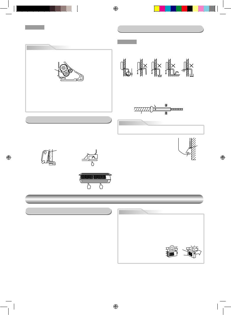
Drainage
1. Run the drain hose sloped downwards.
NOTE
• The hole should be made at a slight downward slant on the outdoor side.
Do not rise the drain hose.
50 mm or more
Do not form the drain hose into a wavy shape.
Do not put the |
Do not put the |
drain hose end |
drain hose end |
into water. |
in the drainage ditch. |
2.Put water in the drain pan and make sure that the water is drained out of doors.
3.When connecting extension drain hose, insulate the connecting part of extension drain hose with shield pipe.
|
Shield pipe |
|
Drain hose |
Inside the room |
Extension drain hose |
|
CAUTION
Arrange the drain pipe for proper drainage from the unit.
Improper drainage can result in dew-dropping.
This air conditioner has the structure designed |
Wall |
|
to drain water collected from dew, which forms |
Drain |
|
on the back of the indoor unit, to the drain pan. |
||
guide |
||
Therefore, do not store the power cord and other |
||
|
||
parts at a height above the drain guide. |
|
|
|
Space for pipes |
OUTDOOR UNIT
Installation Place
•A place which provides the spaces around the outdoor unit as shown in the diagram
•A place which can bear the weight of the outdoor unit and does not allow an increase in noise level and vibration
•A place where the operation noise and discharged air do not disturb your neighbors
•A place which is not exposed to a strong wind
•A place free of a leakage of combustible gases
•A place which does not block a passage
•When the outdoor unit is to be installed in an elevated position, be sure to secure its feet.
•An allowable length of the connecting pipe is up to 20 m.
•An allowable height level is up to 10 m.
•A place where the drain water does not raise any problems
CAUTION
1.Install the outdoor unit without anything blocking the air discharging.
2.When the outdoor unit is installed in a place always exposed to strong wind like a coast or on a high storey of a building, secure the normal fan operation using a duct or a windshield.
3.In particularly windy areas, install the unit such as to avoid admission of wind.
4.Installation in the following places may result in trouble. Do not install the unit in such places.
•A place full of machine oil
•A saline-place such as the coast
• A place full of sulfide gas
• A place where highfrequency waves are likely to be generated as from audio
equipment, welders, and medical equipment
5
1110251206-EN.indd 5 |
9/30/09 11:12:28 AM |
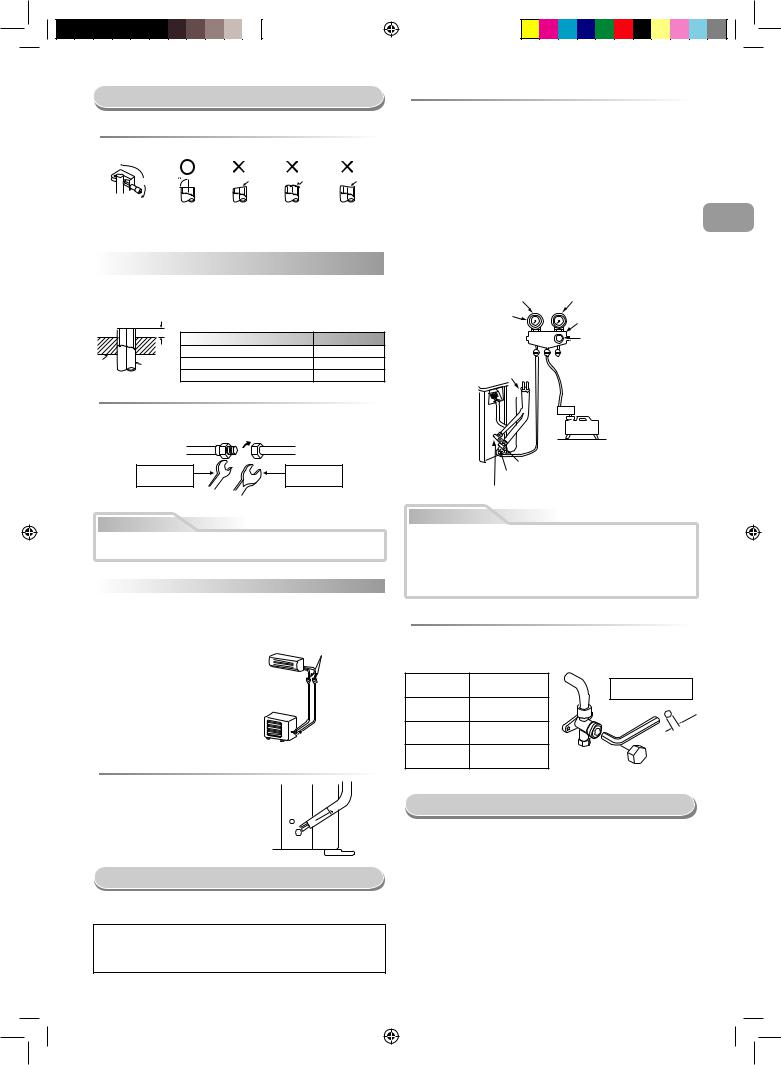
Refrigerant Piping Connection
 Flaring
1. Cut the pipe with a pipe cutter.
90 |
Obliquity |
Roughness |
Warp |
|
|
|
2. Insert a flare nut into the pipe and flare the pipe.
• Projection margin in flaring : A (Unit : mm)
Rigid (clutch type)
Outer dia. |
R410A tool used |
Conventional tool |
|
of copper pipe |
used |
||
|
|||
6.35 |
0 to 0.5 |
1.0 to 1.5 |
|
9.52 |
0 to 0.5 |
1.0 to 1.5 |
|
12.70 |
0 to 0.5 |
1.0 to 1.5 |
Imperial (wing nut type)
|
|
A |
R410A |
|
|
Outer dia. of copper pipe |
|
|
|
6.35 |
1.5 to 2.0 |
Die |
Pipe |
9.52 |
1.5 to 2.0 |
|
|
12.70 |
2.0 to 2.5 |
 Tightening connection
Align the centers of the connecting pipes and tighten the flare nut as far as possible with your fingers. Then tighten the nut with a spanner and torque wrench as shown in the figure.
Half union |
Flare nut |
Externally |
Internally |
threaded side |
threaded side |
Use a wrench to secure. |
Use a torque wrench to tighten. |
CAUTION
Do not apply excess torque. Otherwise, the nut may crack depending on the conditions.
|
(Unit : N·m) |
|
|
Outer dia. of copper pipe |
Tightening torque |
Ø6.35 mm |
16 to 18 (1.6 to 1.8 kgf·m) |
Ø9.52 mm |
30 to 42 (3.0 to 4.2 kgf·m) |
Ø12.70 mm |
50 to 62 (5.0 to 6.2 kgf·m) |
•Tightening torque of flare pipe connections
The operating pressure of R410A
is higher than that of R22 (approx. 1.6 times). It is therefore necessary to firmly tighten the flare pipe connecting sections (which connect the indoor and outdoor units) up to the specified tightening torque. Incorrect connections may cause not only a gas leakage, but also damage to the refrigeration cycle.
Flare at
indoor unit side

 Flare at
outdoor unit side
 Shaping pipes
1.How to shape the pipes
Shape the pipes along the incused line on
the outdoor unit.
2. How to fit position of the pipes  Incused line Put the edges of the pipes to the place with
a distance of 85 mm from the incused line.
Evacuating
After the piping has been connected to the indoor unit, you can perform the air purge together at once.
AIR PURGE
Evacuate the air in the connecting pipes and in the indoor unit using a vacuum pump. Do not use the refrigerant in the outdoor unit. For details, see the manual of the vacuum pump.
 Using a vacuum pump
Be sure to use a vacuum pump with counter-flow prevention function so that inside oil of the pump does not flow backward into pipes of the air conditioner when the pump stops.
(If oil inside of the vacuum pump enters the air conditioner, which use R410A, refrigeration cycle trouble may result.)
1.Connect the charge hose from the manifold valve to the service port of the packed valve at gas side.
2.Connect the charge hose to the port of the vacuum pump.
3.Open fully the low pressure side handle of the gauge manifold valve.
4.Operate the vacuum pump to start evacuating. Perform evacuating for about 15 minutes if the piping length is 20 meters. (15 minutes for 20 meters) (assuming a pump capacity of 27 liters per minute) Then confirm that the compound pressure gauge reading is –101 kPa (–76 cmHg).
5.Close the low pressure side valve handle of the gauge manifold valve.
6.Open fully the valve stem of the packed valves (both gas and liquid sides).
7.Remove the charging hose from the service port.
8.Securely tighten the caps on the packed valves.
Compound pressure gauge
–101 kPa (–76 cmHg)
Handle Lo 
 Charge hose
(For R410A only) 
Connecting pipe
Pressure gauge
Manifold valve
Handle Hi
(Keep full closed)
 Charge hose (For R410A only)
Vacuum pump adapter for counter-flow prevention  (For R410A only)
Vacuum
pump
Packed valve at gas side
Service port (Valve core (Setting pin))
Packed valve at liquid side
CAUTION
•KEEP IMPORTANT 5 POINTS FOR PIPING WORK.
(1)Take away dust and moisture (inside of the connecting pipes).
(2)Tighten the connections (between pipes and unit).
(3)Evacuate the air in the connecting pipes using a VACUUM PUMP.
(4)Check gas leak (connected points).
(5)Be sure to fully open the packed valves before operation.
 Packed valve handling precautions
•Open the valve stem all the way out, but do not try to open it beyond the stopper.
•Securely tighten the valve stem cap with torque in the following table:
Gas side |
50 to 62 N·m |
The hexagon wrench |
|
(Ø12.70 mm) |
(5.0 to 6.2 kgf·m) |
||
is required. |
|||
|
|
||
Gas side |
33 to 42 N·m |
|
|
(Ø9.52 mm) |
(3.3 to 4.2 kgf·m) |
mm |
|
|
|
4 |
|
Liquid side |
14 to 18 N·m |
|
|
(Ø6.35 mm) |
(1.4 to 1.8 kgf·m) |
|
|
Service port |
14 to 18 N·m |
|
|
(1.4 to 1.8 kgf·m) |
|
||
|
|
Wiring Connection
1.Remove the valve cover from the outdoor unit.
2.Connect the connecting cable to the terminals as identified with their respective matched numbers on the terminal block of indoor and outdoor unit.
3.When connecting the connecting cable to the outdoor unit terminals, make a loop as shown in the installation diagram of indoor and outdoor unit to prevent water coming in the outdoor unit.
4.Insulate the unused cords (conductors) from any water coming in the outdoor unit. Proceed them so that they do not touch any electrical or metal parts.
6
EN ES FR IT DE PT PL CZ RU CR HU TR NL GR SV
FI
NO DK RO BG EE LV SK SI
1110251206-EN.indd 6 |
9/30/09 11:12:28 AM |
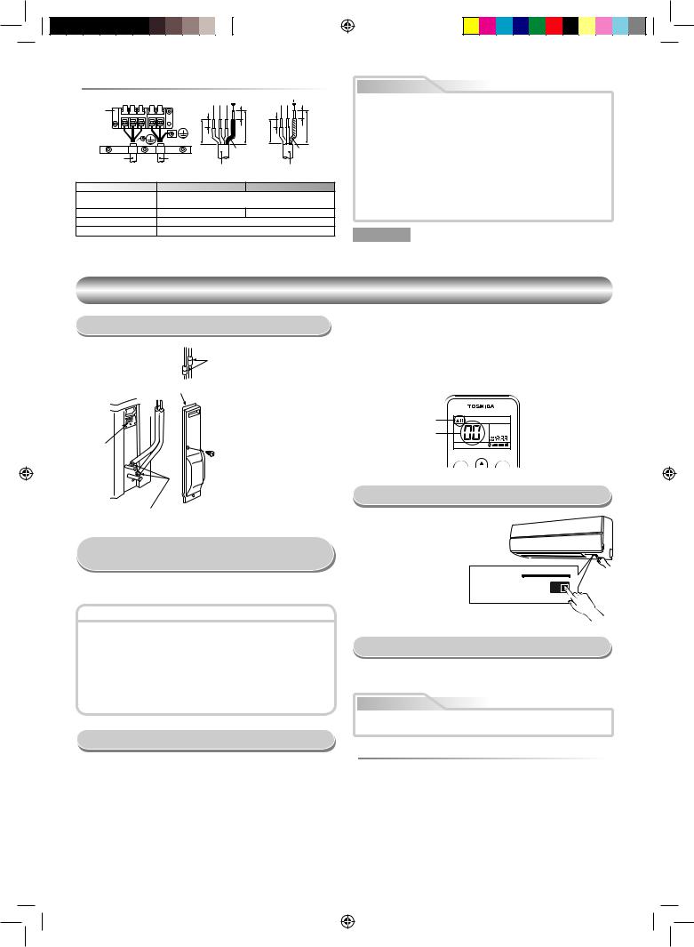
 Stripping length of the connecting cable
|
|
|
|
1 2 3 |
|
L N |
|
Terminal |
1 2 3 |
L N |
|
|
10 |
10 |
|
block |
|
|
|
||||
|
|
|
10 |
|
10 |
|
|
|
|
|
|
40 |
40 |
||
|
|
|
|
30 |
30 |
||
|
|
|
|
|
|
||
|
|
|
|
|
Earth line |
Earth line |
|
Connecting |
|
|
Power |
|
|
|
|
cable |
|
|
cord |
Connecting cable |
Power cord |
|
|
Model |
|
10SKV2 Series |
|
13, 16SKV2 Series |
|||
Power source |
|
|
|
50Hz, 220 – 240 V Single phase |
|
||
|
|
|
60Hz, 220 – 230 V Single phase |
|
|||
|
|
|
|
|
|||
Maximum running current |
|
|
8A |
|
11A |
|
|
Plug socket & fuse rating |
|
|
|
16A |
|
|
|
Power cord |
|
|
|
H07RN-F or 245 IEC66 (1.5 mm2 or more) |
|
||
CAUTION
•Wrong wiring connection may cause some electrical parts burn out.
•Be sure to comply with local cords on running the wire from indoor unit to outdoor unit (size of wire and wiring method, etc.).
•Every wire must be connected firmly.
•This installation fuse (16A) must be used for the power supply line of this air conditioner.
•If incorrect or incomplete wiring is carried out, it will cause an ignition or smoke.
•Prepare the power supply for exclusive use with the air conditioner.
•This product can be connected to the mains.
Connection to fixed wiring: A switch which disconnects all poles and has a contact separation of at least 3 mm must be incorporated in the fixed wiring.
NOTE : Connecting cable
•Wire type : More than H07RN-F or 245 IEC66
OTHERS
Gas Leak Test
Electric parts cover
Check places for the indoor unit.
Valve cover
• Check the flare nut connections for the gas leak with a gas leak detector or soap water.
Check places for the outdoor unit.
Setting of Remote Control
Selector Switch
When two indoor units are installed in the separated rooms, it is not necessary to change the selector switches.
Remote control selector switch
•When two indoor units are installed in the same room or adjacent two rooms, if operating a unit, two units may receive the remote control signal simultaneously and operate. In this case, the operation can be preserved by setting either one indoor unit or remote control to B setting. (Both are set to A setting in factory shipment.)
•The remote control signal is not received when the settings of indoor unit and remote control are different.
•There is no relation between A setting/B setting and A room/B room when connecting the piping and cables.
Remote Control A-B Selection
To separate using of remote control for each indoor unit in case of 2 air conditioner are installed nearly.
Remote Control B Setup.
1.Press RESET button on the indoor unit to turn the air conditioner ON.
2.Point the remote control at the indoor unit.
3.Push and hold [CHK] button on the Remote Control by the tip of the pencil. “00” will be shown on the display.
4.Press [MODE] during pushing [CHK]. “B” will show on the display and “00”
will disappear and the air conditioner will turn OFF. The Remote Control B is memorized.
Note : 1. Repeat above step to reset Remote Control to be A.
2.Remote Control A have not “A” display.
3.Default setting of Remote Control from factory is A.
“B” Display
“00” Display
PRESET |
FAN |
Test Operation
To switch the TEST RUN (COOL) mode, press RESET button for 10 seconds. (The beeper will make a short beep.)
RESET button
Auto Restart Setting
This product is designed so that, after a power failure, it can restart automatically in the same operating mode as before the power failure.
Information
The product was shipped with Auto Restart function in the off position. Turn it on as required.
 How to set the Auto Restart
•Press and hold the RESET button for about 3 seconds. After 3 seconds, the electronic beeper makes three short beeps to tell you the Auto Restart has been selected.
•To cancel the Auto Restart, follow the steps described in the section Auto Restart Function of the owner’s manual.
7
1110251206-EN.indd 7 |
9/30/09 11:12:29 AM |
SICHERHEITSVORKEHRUNGEN
Zur allgemeinen Verwendung bestimmt
Stromversorgungskabel für das Außengerät müssen für den Einsatz im Freien zumindest mit einer Isolierung aus polychloropren ummantelt sein (design H07RN-F) bzw. die Norm 245 IEC66 erfüllen (1,5 mm2 oder mehr). (Die Installation muss in Übereinstimmung mit den örtlichen Vorschriften zur Installation elektrischer Geräte erfolgen.)
VORSICHT |
Installation einer Klimaanlage mit neuartigem Kühlmittel |
|
•IN DIESER KLIMAANLAGE WIRD DAS NEUARTIGE HFC-KÜHLMITTEL (R410A) VERWENDET, DAS DIE OZONSCHICHT NICHT SCHÄDIGT.
Das Kühlmittel R410A ist anfällig für Verunreinigungen durch Wasser, Membranoxidation und Öle, da der Druck des Kühlmittels R410A etwa das 1,6 fache des Drucks beim Kühlmittel R22 beträgt. Zusammen mit dem neuen Kühlmittel wird nun auch ein anderes Kälteanlagenöl verwendet. Achten Sie bei der Installation deshalb darauf, daß kein Wasser, Staub, altes Kühlmittel oder altes Kälteanlagenöl in den Kühlkreislauf der Klimaanlage mit dem neuen Kühlmittel gerät.
Damit es nicht zu einer Vermischung von Kühlmittel und Kälteanlagenöl kommt, haben die Anschlüsse an den Einfüllöffnungen des Hauptgeräts bzw. die Installationswerkzeuge eine andere Größe als bei herkömmlichen Kühlmitteln. Verwenden Sie für die Anschlußleitungen neues Spezialleitungsmaterial für R410A, das frei von Verunreinigungen ist und hohem Druck standhält, so daß Wasser oder Staub nicht eindringen können. Verwenden Sie auch nicht die vorhandenen Leitungen, da diese nicht auf den höheren Druck ausgelegt sind und Verunreinigungen enthalten können.
VORSICHT |
Das gerät muss mit vorgeschalteter Sicherung und Hauptschalter |
|
Das Gerät muss mit einem Trennschalter oder Unterbrecher, der einen Trennabstand von mindestens 3 mm an allen Polen aufweist, an das Stromnetz angeschlossen werden. Die Einbausicherung (25A) muss für die Stromversorgungsleitung dieser Klimaanlage verwendet werden.
GEFAHR
•DIESES GERÄT IST NUR ZUR VERWENDUNG DURCH HIERZU BEFUGTE PERSONEN BESTIMMT.
•VOR ARBEITEN AN DER ANLAGE IST UNBEDINGT DIE STROMZUFUHR ZU UNTERBRECHEN. VERGEWISSERN SIE SICH, DASS ALLE SCHALTER UND SICHERUNGEN AUSGESCHALTEN SIND. WIRD DIES NICHT BEACHTET KANN EIN STROMSCHLAG DIE FOLGE SEIN.
•ACHTEN SIE DARAUF DASS ALLE ELEKTROKABEL ORDNUNGSGEMÄß ANGESCHLOSSEN SIND. INKORREKTER ANSCHLUSS KANN BESCHÄDIGUNGEN DER ELEKTRISCHEN BAUTEILE ZUR FOLGE HABEN.
•VERGEWISSERN SIE SICH BEI DER MONTAGE AUF ORDNUNGSGEMÄßE ERDUNG DES GERÄTES.
•DAS GERÄT NICHT AN ORTEN MIT BRENNBAREN GASEN ODER DÄMPFEN INSTALLIEREN. BRAND ODER EXPLOSION KÖNNTE DIE FOLGE SEIN.
•UM EINER ÜBERHITZUNG DES INNENGERÄTES UND DER DAMIT VERBUNDENEN BRANDGEFAHR ZU VERHINDERN, IST DARAUF ZU ACHTEN DAS GERÄT IN AUSREICHENDEM ABSTAND (2 M) VON WÄRMEQUELLEN WIE HEIZKÖRPERN UND STRAHLERN, ÖFEN, ETC. AUFZUSTELLEN.
•WIRD DAS KLIMAGERÄT IN EINEN ANDEREN RAUM UMMONTIERT IST UNBEDINGT DARAUF ZU ACHTEN, DASS KEINE ANDEREN STOFFE MIT DEM KÄLTEMITTEL (R410A) IN KONTAKT KOMMEN. SOLLTE LUFT ODER ANDERE GASE IN DEN KÄLTEKREISLAUF GELANGEN, KANN DIES ZUM ÜBERMÄßIGEN ANSTEIGEN DES BETRIESBSDRUCKES, ZUM PLATZEN VON LEITUNGEN UND DAMIT ZU VERLETZUNGEN FÜHREN.
•SOLLTEN BEI MONTAGEARBEITEN GRÖßERE MENGEN KÄLTEMITTEL AUS EINER DER LEITUNGEN ENTWEICHEN, SO SOLLTEN DIE ARBEITEN SOFORT UNTERBROCHEN UND DIE RÄUME GUT DURCHLÜFTET WERDEN. BEI ERHITZUNG DES ENTWICHENEN KÄLTEMITTELS DURCH EINE FLAMME O.Ä. BILDEN SICH GESUNDHEITSSCHÄDLICHE SUBSTANZEN.
WARNUNG
•Dieses Gerät darf niemals so modifiziert werden, daß die Sicherheitseinrichtungen durch Verändern der Sperrschalter deaktiviert werden.
•Das Gerät niemals an einem Ort aufstellen, der nicht ausreichend stark abgestützt ist, um das Gewicht des Geräts aufnehmen zu können. Wenn das Gerät umfällt oder sich aus der Verankerung löst, kann dies zu schweren Verletzungen oder Beschädigungen führen.
•Vor Beginn der elektrischen Arbeiten einen zugelassenen Stecker am Netzkabel anbringen. Korrekte Erdung der Anlage sicherstellen.
•Der Einbau des Geräts muß in Übereinstimmungen mit den für das betreffende Land geltenden Verkabelungsvorschriften erfolgen.
Wenn ein Defekt festgestellt wird, darf das Gerät nicht installiert werden. Ziehen Sie in diesem Fall unverzüglich einen TOSHIBA-Händler zu Rate.
VORSICHT
•Kontakt der Anlage mit Wasser oder Feuchtigkeit vor der Installation kann elektrische Schläge zur Folge haben. Das Gerät nicht in einem feuchten Keller lagern; unbedingt die Geräte vor Regen und Feuchtigkeit schützen.
•Nach dem Auspacken den Einbausatz sorgfältig auf Beschädigung überprüfen.
•Das Gerät darf nicht an einem Ort aufgestellt werden, an dem Vibrationen vorhanden sind. Das Gerät keinesfalls an Orten aufstellen, an denen sich das Betriebsgeräusch verstärken kann bzw. an denen Nachbarn durch Geräusch und Abluft belästigt werden könnten.
•Um Verletzungen zu vermeiden, sind scharfkantige Teile mit besonderer Vorsicht zu handhaben.
•Vor Beginn der Einbauarbeiten die Einbauanleitung aufmerksam durchlesen. Die Anleitung enthält weitere wichtige Hinweise, um eine korrekte Montage de Geräte zu gewährleisten.
MELDEPFLICHT AN DAS ÖRTLICHE ENERGIEVERSORGUNGSUNTERNEHMEN
Unbedingt die Installation dieser Anlage vor der Aufstellung dem örtlichen Stromversorger anzeigen. Im Falle von Problemen oder falls die Installation vom Stromversorger nicht genehmigt wird, sorgt der Kundendienst für Abhilfe.
1
1110251206-DE.indd 1 |
10/22/09 3:45:56 PM |
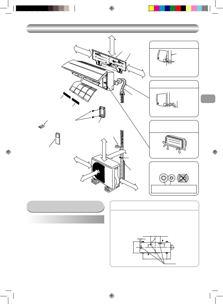
EINBAUZEICHNUNGEN FÜR INNENUND AUSSENGERÄT
170 |
mm |
oder |
|
|
mehr |
||
|
|
||
|
|
|
65 mm oder mehr
Für die hinteren linken und linken
Rohrleitungen.
Haken
1 Montageplatte
Wand
Haken
170 |
mm |
oder |
|
|
mehr |
||
|
|
||
|
|
|
Einen Polster zwischen Innengerät und Wand einbringen um das Innengerät zu neigen und die Montage zu vereinfachen.
 Luftfiter
|
(An |
der |
|
|
|
|
Frontplatte) |
Leitungshülle |
|
|
|
|
||
5 Filter |
|
|
|
|
|
|
6 Filter |
|
|
3 Batterien |
|
|
8 |
|
|
|
|
|
|
|
|
|
Befestigungsschraube |
4 Fernbedienungshalter |
|
|
|
|
Vinylband |
|
|
|
|
Bringen Sie dieses nach |
|
|
|
|
dem Drainagetest an. |
2 Fernbedienungs-Einheit
|
13, 16SAV2 Series |
10SAV2 Series |
|
|
|
A |
100 |
45 |
|
|
|
B |
600 |
400 |
100 |
|
|
mehroder mm600 |
mm |
|
|
|
|
oder |
|
|
|
|
mehr |
|
|
|
|
|
|
|
|
mehr |
|
|
|
er |
|
|
|
od |
|
|
mm |
|
|
|
B |
|
Hinweis :
•Näheres zu den Zubehörund Installationsteilen finden Sie auf dem Zubehörblatt.
•Einige Abbildungen können sich von den aktuellen Teilen unterscheiden.
|
oder |
mehr |
mm |
|
|
|
|
|
A |
|
Sattle |
Verlängerung des Ablaufschlauchs (Nicht erhältlich, wird
vom Installateur gestellt)
600 |
mm |
|
|
|
oder |
|
|
|
|
mehr |
|
|
|
|
Den Ablaufschlauch nicht durchhängen lassen.
Die Leitungsöffnung etwas in Schrägrichtung
einschneiden. DE
Sich vergewissern, daß der Ablaufschlauch nach unten geneigt verläuft.
Die Verbindungsleitungen können nach links, hinten links, hinten rechts, rechts, unterseite rechts oder unterseite links.
Rechts |
|
|
Hinten |
|
|
rechts |
|
|
Unterseite |
Hinten |
Links |
|
||
rechts |
links |
Unterseite links |
|
|
Isolierung der Kühlmittelleitungen
Die Leitungen dürfen nicht zusammen, sondern müssen separat isoliert werden.
Hitzebeständiger Polyethylen-Schaum, 6 mm dick
Zusätzlich erhältliche
Installationsteile
Teile |
Teilebezeichnung |
Menge |
||
code |
||||
|
|
|
||
|
|
|
|
|
|
Kühlmittelleitung |
|
|
|
|
Flüssigkeitsseitig |
: Ø6,35 mm |
|
|
A |
Gasseitig |
: Ø9,52 mm |
Jeweils |
|
|
(10, 13SKV2 Series) |
1 |
||
|
|
|||
|
|
: Ø12,70 mm |
|
|
|
|
(16SKV2 Series) |
|
|
|
|
|
||
B |
Leitungsisoliermaterial |
1 |
||
(polyethylen-Schaum, 6 mm dick) |
||||
|
|
|||
|
|
|
|
|
C |
Dichtungsmasse, PVC-Bänder |
Jeweils |
||
1 |
||||
|
|
|
||
|
|
|
|
|
Anordnung der Befestigungsschrauben der Außeneinheit
•Befestigen Sie die Außeneinheit mit den Befestigungsschrauben und Muttern, falls die Einheit starkem Wind ausgesetzt sein könnte.
•Verwenden Sie Ankerschrauben und Annietmuttern mit Ø8 mm oder Ø10 mm.
•Falls das Ablassen von Kondensat erforderlich ist, vor der Installation einen Ablaufslauchamschluss 9 und die Wasserdichte Kappe ! in die Bodenplatte des Außengeräts einbauen.
|
108 mm |
|
|
125 mm |
|
28 mm |
|
mm |
Lufteinlaß |
|
|
25 |
||
|
|
|
||
|
|
|
|
|
mm |
86 mm |
|
|
102 mm |
320 |
|
|
|
|
Luftauslaß
90 mm
600 mm
Drainageauslaß
2
1110251206-DE.indd 2 |
10/22/09 3:45:57 PM |
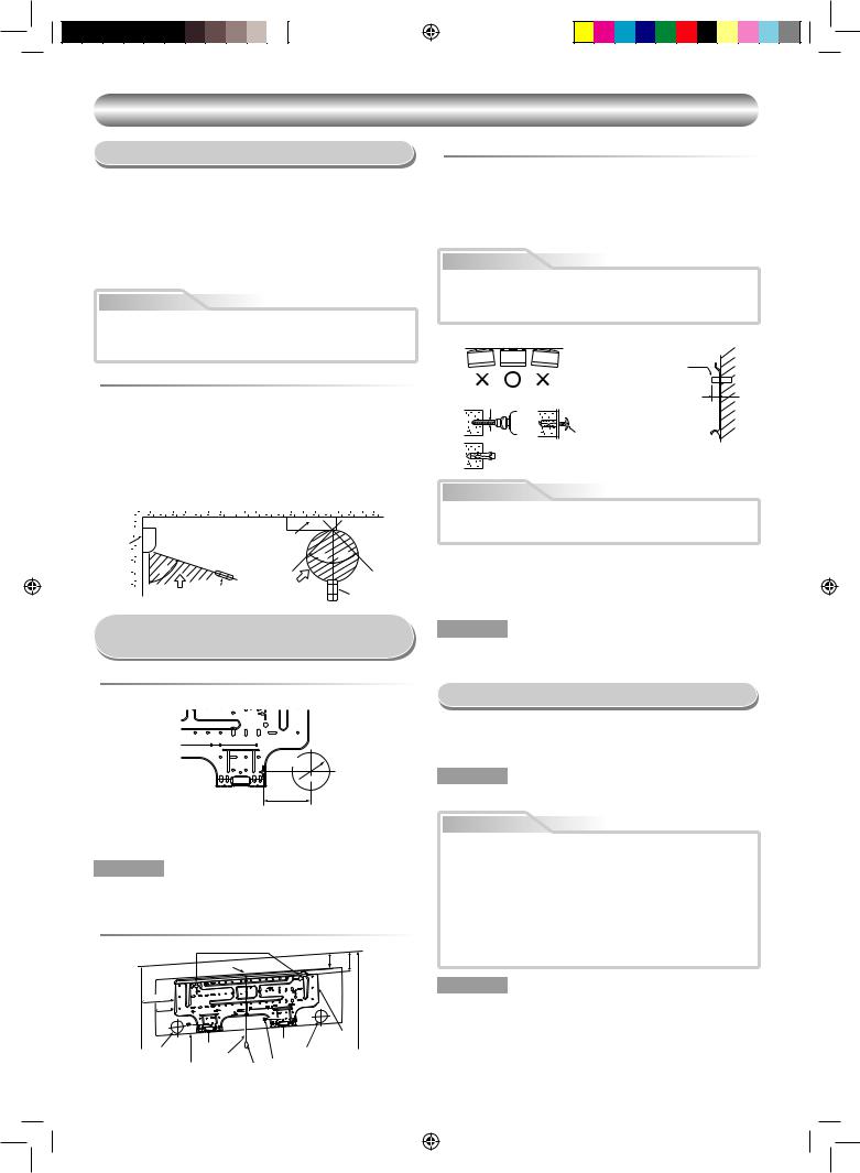
INNENGERÄT
Aufstellungsort
•Einen Aufstellungsort wählen, der wie in der Zeichnung gezeigt ausreichend Platz rund um das Innengerät bietet
•Einen Aufstellungsort wählen, an dem sich keine Hindernisse vor den Einund Auslassöffnungen befinden
•Der Aufstellungsort muss so gewählt werden, dass eine problemlose Verlegung der Kältemittelleitungen gewährleistet ist
•Das Gerät muss so aufestellt werden, dass ein problemloses Abnehmen der Abdeckungen gewährleistet ist
•Dieses Innengerät muss bei Förderhöhen über 2 m installiert werden. Bitte keine Gegenstände auf dem Innengerät ablegen.
VORSICHT
•Direkte Sonnenbestrahlung des Fernbedienungs-Empfängers ist zu vermeiden.
•Der Milkroprozessor im Innegerät darf sich nicht zu nahe an einer einer Radiofrequenz-Signalquelle befinden.
(Für weitere Einzelheiten sich auf die Bedienungsanleitung beziehen.)
 Fernbedienung
•Einen Aufstellort wählen, an dem sich keine Hindernisse wie zum Beispiel ein Vorhang-zwischen Fernbedienung und Empfänger befinden, die einen einwandfreien Empfang des Signals verhindern können
•Die Fernbedienung nicht an einer Stelle anbringen, die einer direkten Sonnenbestrahlung ausgesetzt oder sich in der Nähe einer Wärmequelle befindet, wie zum Beispiel einem Ofen.
•Die Fernbedienung mindestens 1 m vom nächsten Fernsehgerät oder einer Stereoanlage entfernt aufbewahren. (Dies ist erforderlich, um Bildstörungen oder Störgeräusche zu vermeiden.)
•Die Position der Fernbedienung ist entsprechend der nachstehenden Abbildung zu bestimmen.
Innengerät |
(Seitenansicht) |
(Ansicht von oben) |
|
|
|
|
Innengerät |
|
|
|
|
|
|
4 |
5° |
|
° |
|
|
5 |
|||
|
|
|
4 |
|
|
|
° |
|
|
|
|
|
5 |
Fernbedienung Empfangsbereich |
|
|
|
|
7 |
|
|
|
|
|
Empfangsbereich |
|
|
Fernbedienung |
|
Mauerdurchbruch und
Befestigung der Montageplatte
 Bohren der Maueröffnung
Zur Installation der Kältemittelleitungen an der Rückseite
80 |
100 |
180 |
Leitungsöffnung

 65 mm
65 mm
Der Mittelpunkt der
Leitungsöffnung befindet sich
100 mm
über der Pfeilmarkierung.
 Befestigung der Montageplatte unmittelbar an der Wand
1.Die Montageplatte im oberen und unteren Bereich fest an der Wand montieren, um ein sicheres Einhängen des Innengeräts zu gewährleisten.
2.Um die Montageplatte an einer Betonwand mit Hilfe von Dübelschrauben zu befestigen, sind die Verankerungs-Bohrungen zu verwenden, wie in der obigen Abbildung gezeigt.
3.Die Montageplatte horizontal an der Wand montieren.
VORSICHT
Beim Befestigen der Montageplatte unter Verwendung von Linsenkopfschraube dürfen die Öffnungen für die Dübelschrauben nicht verwendet werden. Wenn dies nicht beachtet wird, kann das Gerät herunterfallen und Verletzungen bzw. Beschädigungen verursachen.
Montageplatte (Waagerecht montieren.)
|
Verankerungsschraube |
|
Bohrung, Durchmesser 5 mm |
Überstan: 15 mm |
|
oder weniger |
||
|
7 Linsenkopfschraube
Ø4 x 25R
 Dübel
Dübel
(Örtliche Teile)
VORSICHT
Unbedingt darauf achten, daß das Gerät sicher befestigt ist; wenn dies nicht beachtet wird, kann das Gerät herunterfallen und schwere Verletzungen oder Beschädigungen verursachen.
•Bei Wänden aus Fertigbausteinen, Ziegelsteinen, Beton oder ähnlichen Materialien sind Löcher mit einem Durchmesser von 5 mm in die Wand zu bohren.
•Die Dübel zur Aufnahme der dafür vorgesehenen Linsenkopfschrauben 7 in die Löcher einsetzen.
HINWEIS
•Sichern Sie bei der Installation die vier Ecken und die unteren Teile der Montageplatte mit 4 bis 6 Linsenkopfschrauben.
Elektrische Anschlüsse
1.Die Versorgungsspannung muß den gleichen Wert wie die Nennspannung des Klimageräts aufweisen.
2.Die Stromquelle muß zur ausschließlichen Verwendung des Klimageräts dienen.
HINWEIS
• Kabeltyp : Über H07RN-F oder 245 IEC66
1.Nach dem die Position des Durchbruches mit Hilte der Montageplatte (¨) bestimmt wurde, ist die Bohrung (Ø65 mm) mit leichtem Gefälle nach außen anzulegen.
HINWEIS
•Beim Bohren einer Wand, die durch Metall-Leisten, Maschendraht oder eine Metallplatte verstärkt ist, muß ein separat erhältlicher Lochbohreinsatz verwendet werden.
 Befestigung der Montageplatte
Ankerschraubenloch
|
Haken |
|
62 |
82,5 |
Bodenvom |
|
|
|
|
||
170 |
|
|
|
|
mehroderm |
85 |
|
|
|
|
|
|
|
Haken |
|
1 |
2 |
|
Haken |
Montageplatte |
|||
|
|
||||
Leitungsöffnung |
|
|
|||
Leitungsöffnung |
|
|
|||
Schnur |
|
|
|||
|
Gewicht 7 Linsenkopfschraube |
|
|||
Innengerät |
|
||||
3
VORSICHT
•Das Gerät kann auf eine der folgenden Weisen am Netz angeschlossen werden.
(1)Festverdrahtung:
Ein Trennschalter oder Unterbrecher, der alle Pole trennt und einen Trennabstand von mindestens 3 mm aufweist, muß bei einer Festverdrahtung mit eingebaut werden. Dabei ist ein geprüfter Trennschalter oder Unterbrecher zu verwenden.
(2)Netzanschluss:
Den Netzstecker mit dem Netzkabel verbinden und an eine Steckdose anschließen. Netzkabel und -stecker müssen den Vorschriften entsprechen.
HINWEIS
•Führen Sie die Verkabelungsarbeiten so aus, dass eine großzügig ausgelegte Kapazität der Verkabelung zur Verfügung steht.
1110251206-DE.indd 3 |
10/22/09 3:45:59 PM |
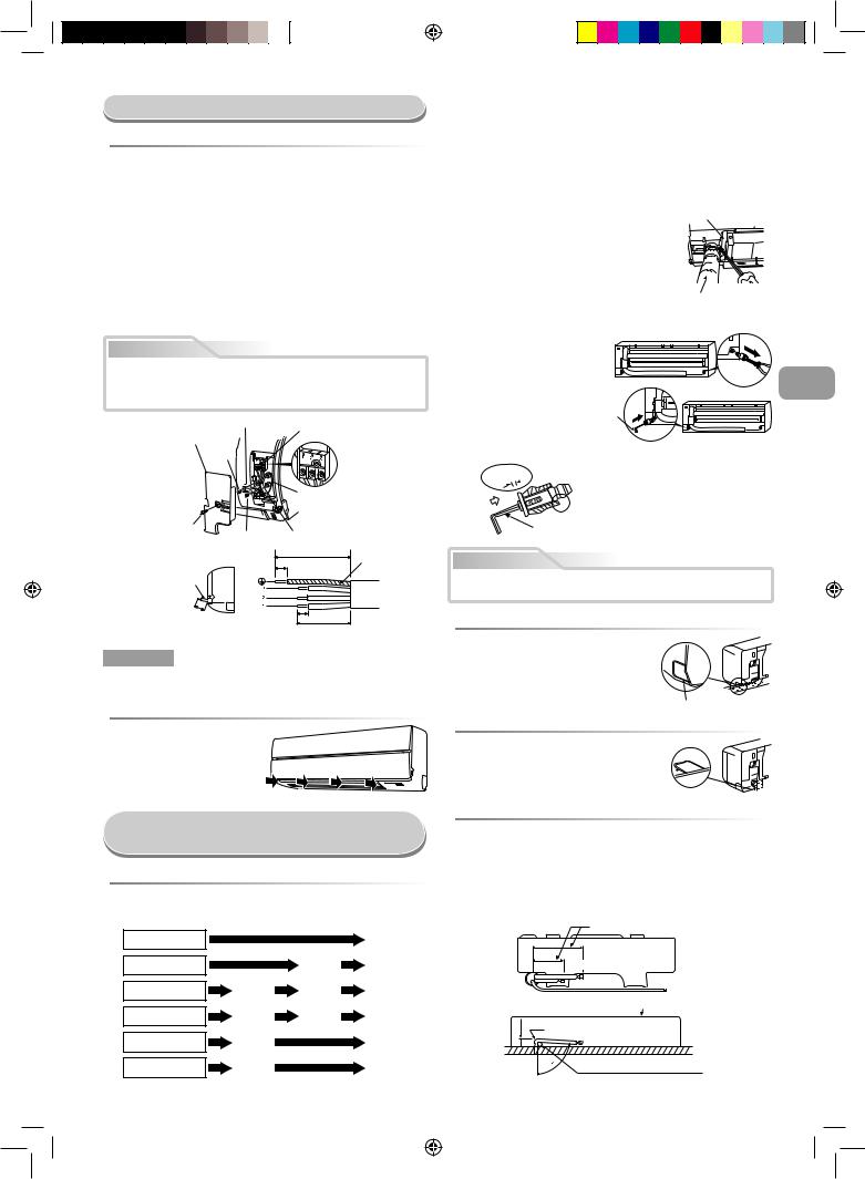
Kabelanschlüsse
 Verbinden des Verbindungskabels
Das Anschließen des Verbindungskabels kann vorgenomen werden, ohne daß hierzu die Frontplatte abgenommen werden muß.
1.Nehmen Sie das Lufteinlaßabdeckgitter ab.
Öffnen Sie das Lufteinlaßabdeckgitter nach oben, und ziehen Sie es auf sich zu.
2.Die Klemmenabdeckung und die Zugentlastung abnehmen.
3.Das Verbindungskabel (in Übereinstimmung mit örtlichen Vorschriften) durch die Leitungsöffnung in der Wand führen.
4.Das Verbindungskabel aus dem Schlitz an der Rückwand ziehen, so dass es vorn etwa 15 cm übersteht.
5.Das Verbindungskabel ganz in den Klemmenblock einschieben und mit den Schrauben gut sichern.
6.Anzugsmoment : 1,2 N·m (0,12 kgf·m)
7.Das Verbindungskabel mit der Zugentlastung sichern.
8.Fixieren Sie die Anschlußabdeckung, die Rückplattendüse und das Lufteinlaßabdeckgitter an der Inneneinheit.
VORSICHT
•Beim Anschluß sich unbedingt auf den Stromlaufplan an der Innenseite der Frontplatte beziehen.
•Vor Beginn der Arbeiten sich mit örtlichen Bestimmungen, spezifischen Kabelverlegungsvorschriften und Beschränkungen vertraut machen.
Kabelklammer
Klemmenblock
Klemmenabdeckung
Schraube
Massekabel
Schraube
Schraube Verbindungskabel
110 mm
Massekabel
10 mm
Verbindungskabel
ca. |
|
|
15 |
cm |
10 mm |
|
|
50 mm
Zu entfernende Isolierung des Verbindungskabels
HINWEIS
•Nur gelitzten Leiter verwenden.
•Kabeltyp : H07RN-F oder mehr
 So installieren Sie das Lufteinlaßabdeckgitter an der Inneneinheit
• Wenn Sie das Lufteinlaßabdeckgitter anbringen wollen, führen Sie die Schritte zum Entfernen des Gitters einfach in umgekehrter Reihenfolge aus.
1.Ausschneiden des Frontplattenschlitzes
Den Schlitz an der linken oder rechten Seite der Frontabdeckung für Anschluss an der linken bzw. rechten Seite sowie den Schlitz an der linken oder rechten Unterseite der Frontabdeckung für Anschluss an der linken bzw. rechten Unterseite ausschneiden.
2.Wechseln des Kondensatschlauchs
Für Leitungsanschluss an der linken Seite, Unterseite links bzw. Rückseite links müssen Kondensatschlauch und –kappe geändert werden.
Entfernen des Kondensatschlauchs
•Der Drainage-Schlauch kann durch Entfernen der Schraube vom Drainage-Schlauch herausgenommen werden.
•Seien Sie beim Entfernen des Drainage-Schlauchs mit den scharfen Kanten der Stahlplatte vorsichtig. Sie können sich an den Kanten verletzten.
•Setzen Sie den Drainage-Schlauch zur Montage so fest ein, bis das Verbindungsstück mit dem
Wärmeisolator Kontakt hat. Befestigen Sie es mit der Original-Schraube.
Hitzeschutz
Ablaufschlauch
Entfernen der Kondensatkappe |
|
|
Die Kondensatkappe mit einer |
|
|
Spitzzange lösen und herausziehen. |
|
|
Anbringen der Kondensatkappe |
DE |
|
1) Sechskant-Inbusschlüssel |
|
|
(4 mm) in Öffnung |
4 mm |
|
einpassen. |
|
|
2) Kondensatkappe bis zum Anschlag einführen. |
|
|
Kein |
|
|
Zwischenraum |
|
|
Vor dem Einführen der Ablasskappe
 kein Schmiermittel (Kältemittelöl) auftragen. Anderenfalls können Schäden und Undichtigkeit
am Stopfen resultieren.
Inbusschlüssel (4 mm) einführen.
VORSICHT
Kondensatschlauch und Ablasskappe ordnungsgemäß fixieren, damit keine Wasserleckage entsteht.
 Bei Leitungsanschluss rechts oder links
•Nach dem Einschlitzen der Frontplatte mit einem Messer oder Abreißstift eine Öffnung mit einer Zange o. Ä. vorbereiten.
Schlitz
 Bei Leitungsanschluss an Unterseite rechts oder links
• Nach dem Einschlitzen der Frontplatte
mit einem Messer oder Abreißstift
eine Öffnung mit einer Zange o. Ä. Schlitz  vorbereiten.
Installation von Leitungen und
Kondensatschlauch
 Verlegung von Leitungen und Kondensatablauf
*Da Kondensation zu Störungen des Geräts führen können, unbedingt beide Anschlussleitungen isolieren. (Als lsoliermaterial ist Polyethylen-Schaum zu verwenden.)
Hinten rechts
Hinten links
Unterseite links
Links
Unterseite rechts
Rechts
|
|
|
|
|
|
|
Leitungsvorbereitung |
|
|
|
|
Wechseln des |
Kondensat- |
schlauchs |
|
||
Ausschneiden des |
Frontplattenschlitzes |
|||||||
|
|
|
|
|
||||
|
|
|
|
|
|
|
|
 Nach links weisende Anschlußleitung
•Die Anschlußleitung so biegen, daß diese 43 mm von der Wandoberflhe verlft. Wenn der Wand-Abstand der Anschlußleitung 43 mm übersteigt, kann das Innenger nicht sicher an der Wand befestigt werden.
Beim Biegen der Anschlußleitung ein Federbiegeger verwenden, um ein Zerquetschen der Leitung zu vermeiden.
Die Anschlußleitung mit einem Radius von weniger als 30 mm biegen.
Anschlußleitung nach dem Einbau des Geräts (Abbildung)
(An der Vorderkante des Bördelrands)
|
270 mm |
Gasseite |
|
|
|
||
|
230 mm |
Flüssigkeitesseite |
|
|
|
||
|
|
Außenseite des Innengeräts |
|
mm |
R 30 mm (Verwenden Sie Polisin - |
||
Polyethylenkern oder etwas Ähnliches |
|||
43 |
|||
für gebogene Leitung.) |
|||
|
|||
|
|
Den Griff eines Schraubendrehers |
|
|
80 |
o.ä. verwenden. |
|
4
1110251206-DE.indd 4 |
10/22/09 3:46:01 PM |
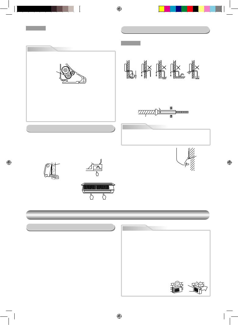
HINWEIS
Wenn die Leitung nicht korrekt gebogen wird, kann das Innengerät nicht fest an der Wand befestigt werden.
Nach dem die Leitungen durch die Leitungsöffnung geführt wurden, sind die Anschlüsse zu verbinden; danach sind beide Leitungen zu Isolieren.
VORSICHT
•Die Zusatzleitungen (zwei) und das Verbindungskabel mit Isolierband fest zusammenbinden. Bei nach links oder hinten links gerichteten Leitungen sind nur die Zusatzleitungen (zwei) mit Isolierband zusammenzubinden.
 Innengerät
Zusatzleitungen 

 Verbindungskabel
Montageplatte 
•Die Leitungen so anordnen, daß keine der Leitungen aus der Rückplatte des Innengeräts hervorsteht.
•Die Zusatzleitungen und Anschlußleitungen zusammenbinden, dann das Isolierband an der Anschlußleitung abschneiden, um ein doppeltes Umwicheln der Verbindungsstelle zu vermeiden; außerdem sind die Anschlußstellen mit Vinylband o.ä. zu umwickeln.
•Da die Bildung von Kondensationswasser zu Funktionsstörung des Geräts führen kann, müssen beide Anschlußleitungen isoliert werden. (Als lsoliermaterial ist Polyethylen-Schaum zu verwenden.)
•Beim Biegen einer Leitung darauf achten, daß die Leitung nicht beschädigt wird.
Entwässerung
1. Den Ablaufschlauch nach unten weisend anbringen.
HINWEIS
•Die Öffnung muß so angelegt werden, daß sie zur Außenseite hin schräg nach unten weist.
Den Ablaufschlauch |
Den Ablaufschlauch |
|
nicht nach oben verlegen. |
nicht wellenförmig biegen. |
|
50 mm |
|
|
oder mehr |
|
|
Das Ende des |
|
Das ende des |
Ablaufschlauchs |
ablaufschlauchs |
|
nicht in Wasser einlegen. |
nicht in einen |
|
|
|
Abwasserkanal einlegen. |
2.Die Ablaufwanne mit Wasser füllen und sich vergewissern, daß das Wasser problemlos nach außen abläuft.
3.Beim Anschließen der Ablaufschlauch-Verlängerung ist die Verbindungsstelle der Ablaufschlauch-Verlängerung mit der Leitungshülle abzudecken.
|
Leitungshülle |
|
|
Ablaufschlauch |
Innenseite des |
Verlängerung des |
|
Raums |
Ablaufschlauchs |
||
|
Einbau des Innengeräts
1.Die Leitungen durch die Öffnung in der Wand führen, dann das Innengerät in die oberen Haken der Montageplatte einhängen.
2.Das Innengerät nach rechts und links drücken, um sich zu vergewissern, daß das Gerät fest auf der Montageplatte aufgehängt ist.
3.Das Innengerät im unteren Bereich gegen die Wand drücken und den unteren Teil des Gerät an der Montageplatte einhängen. Am unteren Bereich des Innengeräts zur Person ziehen, um sich zu vergewissern, daß das Gerät fest auf der Montageplatte aufsitzt.
Hier einhängen.
1
 1 Montageplatte
2
Haken
•Um das Innengerät wieder von der Montageplatte abzunehmen, das Gerät zur Person ziehen, und gleichzeitig die Unterseite an den bezeichneten Stellen hochdrücken.
Drücken
(Aushaken)
Drücken Drücken
VORSICHT
Den Ablaufschlauch korrekt verlegen, um eine einwandfreie Entwässerung zu gewährleisten.
Wenn das Wasser nicht einwandfrei abläuft, kann dies eine Beschädigung von Gegenständen verursachen.
Dieses Klimagerät ist so konstruiert, |
|
|
Wand |
daß das an der Geräterückseite |
|
|
|
anhaftende Kondenswasser in die |
|
|
Ablaufführung |
Ablaufwanne abgeleitet wird. Aus |
|
|
|
diesem Grund dürfen Netzkabel und |
|
|
|
andere Komponenten nicht an der |
Für Leitungen |
|
|
Ablaufführung verlegt werden. |
|
||
vorgesehener Bereich |
|
|
|
AUSSENGERÄT
Aufstellungsort
•Einen Aufstellort wählen, der ausreichend Platz rund um das Außengerät bietet, wie in der Zeichnung gezeigt
•Das Gerät an einem Ort aufstellen, der das Gewicht des Geräts aufnehmen kann und an dem das Betriebsgeräusch sowie die Vibrationen des Geräts nicht verstärkt werden
•Einen Ort wählen, an dem das Geräusch bzw. die Auslaßluft nicht zu einer Belästigung der Nachbarn führen könnte
•Der Aufstellort sollte möglichst vor starker Windeinwirkung geschützt sein.
•Am Aufstellort dürfen keine brennbaren Gase vorhanden sein
•Das Gerät darf nicht so aufgestellt weden, daß es zu einer Durchgangsbehinderung führt
•Wenn das Außengerät in einer erhöhten Position montiert werden soll, müssen die Füße unbedingt gesichert werden.
•Die für den Anschluss erlaubte Länge beträgt 20 m.
•Die erlaubte Höhe beträgt bis zu 10 m.
•Das Gerät an einem Ort aufstellen, an dem das Ablaufwasser keine Probleme verursacht
VORSICHT
1.Das Außengerät so installieren, daß die Luftauslässe nicht blockiert sind.
2.Wenn das Außengerät an einer Stelle montiert wird, die starken Windeinwirkungen ausgesetzt ist, wie zum Beispiel in Meeresnähe oder in den oberen Stockwerken eines Hochhauses, muß das Gebläse mit einer Windhutze oder einer Abschirmung versehen werden, um einen normalen Betrieb des Gebläses zu gewährleisten.
3.In Gebieten mit starken Winden das Gerät an windgeschützten Stellen installieren.
4.Eine Installation an folgenden Orten kann zu Problemen führen. Installieren Sie das Gerät daher nicht an solchen Orten.
•Orte, die mit Maschinenöl verunreinigt sind
•Salzreiche Umgebung, zum Beispiel an der Küste
•Orte, an denen Schwefelgas vorkommt
•Orte, an denen es zu Hochfrequenzwellen, ausgelöst zum Beispiel durch Audiogeräte,
Schweißgeräte und medizinische Geräte, kommenkann
5
1110251206-DE.indd 5 |
10/22/09 3:46:03 PM |

Anschluß der Kühlmittelleitungen
 Bördeln
1. Die Leitung mit einem Rohrschneider abschneiden.
90 |
Abschrung |
Unebenheit |
Verzug |
|
|
|
2.Setzen Sie einen Doppelring in die Leitung ein, und weiten Sie die Leitung.
• Überstand beim Weiten : A (Einheit : mm)
Starr (Typ Kupplung)
Außendurchmesser |
Bei Verwendung von |
Bei Verwendung von |
der Kupferleitung |
R410A-Werkzeug |
herkömmlichem Werkzeug |
6,35 |
0 bis 0,5 |
1,0 bis 1,5 |
9,52 |
0 bis 0,5 |
1,0 bis 1,5 |
12,70 |
0 bis 0,5 |
1,0 bis 1,5 |
Imperial-Werkzeug (Typ Flügelmutter)
|
A |
Außendurchmesser der |
|
|
|
|
R410A |
||
|
|
Kupferleitung |
||
|
|
|
||
Druck |
Leitung |
6,35 |
1,5 bis 2,0 |
|
platte |
9,52 |
1,5 bis 2,0 |
||
|
||||
|
|
12,70 |
2,0 bis 2,5 |
 Festziehen der Verbindungsmutter
Die anzuschließenden Leitungen zu den Anschlüssen ausrichten, dann die Überwurfmuttern so weit wie möglich mit den Fingern festdrehen.
Überwurfmutter 

 Kontermutter
Seite mit |
Seite mit |
Außengewinde |
Innengewinde |
Zum Festziehen einen |
Zum Festziehen eine |
Schraubenschlüssel verwenden. |
Drehmomentschlüssel verwenden. |
 Verwendung der Vakuumpumpe
Verwenden Sie unbedingt eine Vakuumpumpe mit Rückflußschutz, so daß Öl im Inneren der Pumpe nicht zurück in die Leitungen der Klimaanlage fließt, sobald die Pumpe stoppt.
(Wenn Öl aus dem Inneren der Vakuumpumpe in eine Klimaanlage mit R410A gerät, kann es zu Störungen des Kühlzyklus kommen.)
1.Verbinden Sie den Füllschlauch vom Verteilerventil mit der Wartungsöffnung des gasseitigen Kompaktventils.
2.Verbinden Sie den Füllschlauch mit der Öffnung der Vakuumpumpe.
3.Öffnen Sie den Niederdruckseitengriff des Meßverteilerventils vollständig.
4.Starten Sie die Vakuumpumpe, so daß die Entleerung beginnt. Führen Sie den Entleerungsvorgang bei einer Leitungslänge von 20 m etwa 15 Minuten lang durch. (d. h. 15 Minuten für 20 m bei einer Pumpkapazität von 27 l pro Minute) Vergewissern Sie sich dann, daß der gesamte Druckmeßwert –101 kPa (–76 cmHg) beträgt.
5.Schließen Sie den Niederdruckseitengriff des Meßverteilerventils.
6.Öffnen Sie den Ventilschaft der Service Ventile vollständig (gasund flüssigkeitsseitig).
7.Lösen Sie den Füllschlauch von der Wartungsöffnung.
8.Befestigen Sie die Kappen auf den Service Ventile.
Verbindung Druckmeßgerät |
Druckmeßgerät |
–101 kPa |
|
(–76 cmHg) |
Verteilerventil |
|
Grift der Unterdruckseite |
Griff der Hochdruckseite (Bleiben |
DE |
|
||
Zufuhrschlauch |
Sie vollständig geschlossen) |
|
|
|
|
(Für R410A nur) |
Zufuhrschlauch |
|
Angeschlossenen Leitungen |
(Für R410A nur) |
|
|
|
|
|
Anpassungsvorrichtung von |
|
|
Vakuumpumpe für Verhütung |
|
|
gegenüberliegender |
|
|
Strömung (Für R410A nur) |
|
Vakuum-
pumpe
Absperventil am Gasseite
Wartungsöffnung (Ventil-kern (Einstellung Nadel))
Absperrventil am Flüssigkeitsseite
VORSICHT
Darauf achten, daß die Mutter nicht zu fest angezogen wird. Bei zu starkem Anziehen kann sich die Mutter unter gewissen Betriebsbedingungen spalten.
|
(Einheit : N•m) |
|
|
Außendurchmesser der Kupferleitung |
Anzugsdrehmoment |
Ø6,35 mm |
16 bis 18 (1,6 bis 1,8 kgf·m) |
Ø9,52 mm |
30 bis 42 (3,0 bis 4,2 kgf·m) |
Ø12,70 mm |
50 bis 62 (5,0 bis 6,2 kgf·m) |
• Drehmoment für die Leitungsverbindung mit Weitung
Der Druck steigt bei R410A höher an als bei R22 (ca. 1,6 mal). Ziehen Sie daher die Leitungsverbindungen mit Weitung zwischen Innenund Außeneinheit mit einem Drehmomentschlüssel fest an, bis das angegebene Drehmoment erreicht ist. Bei fehlerhaften Verbindungen kann nicht nur Gas austreten, sondern es kann auch zu Problemen mit dem Kühlzyklus kommen.
Weitung an
Inneneinheit
Weitung an
Außeneinheit
 Ausrichten der Leitungen
1.Anleitung für das Ausrichten Die Leitungen entlang der Markierungslinie auf dem Außengerät ausrichten.
2. Positionseinstellung der Leitungen Die
Markierungslinie
Leitungsenden in einem Abstand von 85 mm zur Markierungslinie anbringen.
Entleeren
Sobald das Leitungen an der Innenund Außeneinheit angeschlossen sind, kann mit dem Evakuieren begonnen werden.
ENTLÜFTUNG
Die in den Leitungen und im Innengerät enthaltene Luft und Feuchtigkeit muss mit Hilfe einer Vakuumpumpe abgesaugt werden. Kein Kältemittel zum „Ausblasen“ der Leitungen verwenden! Weiter Einzelheiten bitte der Betriebsanleitung der Vakuumpumpe zu entnehmen.
VORSICHT
•5 WICHTIGE HINWEISE ZU ARBEITEN AN DEN LEITUNGEN
(1)Staub und Verschmutzung sind restlos zu entfernen (Innenseite der Anschlußleitungen).
(2)Alle Verbindungen gut festziehen (zwischen Leitungen und dem Gerät).
(3)Die in den Leitungen enthaltenen Fremdgase und Luftfeuchtigkeit sind mit einer Vakuumpumpe abzusaugen.
(4)Das Gerät auf Gasverlust überprüfen (an den Verbindungsstellen).
(5)Stellen Sie sicher, die Service Ventile vor dem Betrieb vollständig zu öffnen.
 Sicherheitshinweise zu den Service-Ventilen
•Öffnen Sie den Ventilschaft vollständig. Versuchen Sie jedoch nicht, den Ventilschaft über den Stopper hinaus zu öffnen.
•Ziehen Sie die Ventilschaftkappe mit dem in der folgenden Tabelle genannten Drehmoment fest:
Gasseitig |
50 bis 62 N·m |
Ein Inbusschlüssel |
|
(Ø12,70 mm) |
(5,0 bis 6,2 kgf·m) |
||
ist erforderlich. |
|||
Gasseitig |
33 bis 42 N·m |
|
|
(Ø9,52 mm) |
(3,3 bis 4,2 kgf·m) |
mm |
|
Flüssigkeitsseitig |
14 bis 18 N·m |
4 |
|
|
|||
(Ø6,35 mm) |
(1,4 bis 1,8 kgf·m) |
|
|
Wartungsöffnung |
14 bis 18 N·m |
|
|
|
(1,4 bis 1,8 kgf·m) |
|
Kabelanschlüsse
1.Die Ventilabdeckung vom Außengerät abnehmen.
2.Das Anschlußkabel mit der entsprechenden Anschlußklemme verbinden, und hierbei sich auf die dazugehörigen Nummern des Klemmenblocks am Innen-bzw. Außengerät beziehen.
3.Wenn das Anschlußkabel mit den Klemmen des Außengerätes verbunden wird, ist eine Schleife zu bilden, die der Abbildung in der Einbauzeichnung das Innen-bzw. Außengerät entspricht; dies dient dazu, ein Eindringen von Wasser in das Außenger zu vermeiden.
4.Unbeschaltete Kabel (Leiter) isolieren und vor Wasser in der Außeneinheit schützen. Die Kabel so verlegen und abisolieren, dass sie keine stromführenden oder metallenen Teile berühren.
6
1110251206-DE.indd 6 |
10/22/09 3:46:05 PM |
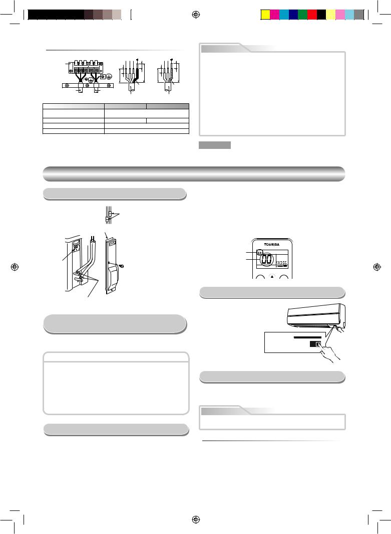
 Zu entfernende Isolierung des Verbindungskabels
|
|
1 2 3 |
L |
N |
Klemmenblock |
|
10 |
|
10 |
1 2 3 L N |
|
|
||
|
10 |
40 |
10 |
40 |
|
30 |
30 |
||
|
|
|
||
|
|
Massekabel |
Massekabel |
|
Verbindungskabel |
Netzkabel |
|
|
|
|
Verbindungskabel |
Netzkabel |
||
Modell |
10SKV2 Series |
13, 16SKV2 Series |
||
Stromversorgung |
|
50Hz, 220 – 240 V Einphasig |
||
|
60Hz, 220 – 230 V Einphasig |
|||
|
|
|||
Max. Betriebsstrom |
|
8A |
|
11A |
Steckdosenund Sicherungsvorgaben |
|
16A |
|
|
Netzkabel |
H07RN-F oder 245 IEC66 (1,5 mm2 oder mehr) |
|||
VORSICHT
•Auf korrekten Anschluß der Kabel achten, da eine inkorrekte Verbindung eine Beschädigung von elektrischen Komponenten zur Folge hat.
•Hinsichtlich der Verkabelung von Innenund Außengerät unbedingt die örtlichen Vorschriften (Kabelquerschnitt, Kabelführung usw.) befolgen.
•Jedes Kabel muß fest angeschlossen werden.
•Diese Einbausicherung (16A) muss für die Stromversorgungsleitung dieser Klimaanlage verwendet werden.
•Bei inkorrekter oder unvollständiger Verkabelung besteht Gefahr von Brand oder Rauch.
•Dieses Netzkabel ausschließlich für die Klimaanlage verwenden.
•Dieses Produkt kann an das Stromversorgungsnetz angeschlossen werden.
Anschluss an feste Verkabelung: Ein Schalter, der alle Pole trennt und eine Kontaktunterbrechung von mindestens 3 mm aufweist, muss in die feste Verkabelung integriert werden.
HINWEIS : Verbindungskabel
• Kabeltyp : Über H07RN-F oder 245 IEC66
SONSTIGES
Überprüfung auf Gas-Undichtigkeit
Die Aufstellorte für das
Innengerät prüfen.
Ventilabdeckung
Abdeckung der |
|
elektrischen |
• Mit einem Gasleckdetektor |
Anschlüsse |
oder mit Seifenwasser die |
|
|
|
Überwurfverbindungen auf |
|
Undichtigkeiten prüfen. |
Die Aufstellorte für das
Außengerät prüfen.
Einstellen des Fernbedienungs-Wahlschalters
Wenn zwei Innengeräte in getrennten Räumen installiert sind, müssen die Wahlschalterstellungen nicht verändert werden.
Fernbedienungs-Wahlschalter
•Werden zwei Innengeräte im selben Raum oder in angrenzenden Räumen installiert, könnte bei Fernbedienung eines Geräts auch das andere Gerät auf das Fernbedienungssignal reagieren. Um eine separate Bedienung zu gewährleisten, sind in diesem Fall ein Innengerät und eine Fernbedieung auf Zuordnung „B“ umzustellen (die Werkseinstellung ist A.)
•Wenn die Zuordnung von Innengerät und Fernbedienung nicht übereinstimmt, spricht das Innengerät nicht auf die Fernbedienung an.
•Beim Verlegen von Leitungen und Kabeln für Raum A und B besteht kein Zusammenhang mit den Fernbedienungszuordnungen „A“ und „B“.
Fernbedienung A-B Wahl
Werden 2 Klimageräte installiert, muss die Fernbedienung für jedes Innengerät getrennt werden.
Fernbedienung B-Setup.
1.Drücken Sie am Innengerät die RESET-Taste, um das Klimagerät anzustellen.
2.Richten Sie die Fernbedienung auf das Innengerät.
3.Halten Sie die Taste [CHK] auf der Fernbedienung mit der Spitze eines Bleistifts gedrückt. „00“ wird im Display angezeigt.
4.Die Tasten [MODE] und [CHK] gleichzeitig drücken. Die Zuordnung „B“ erscheint im Display. „00“ verschwindet im Display und das Klimagerät wird ausgeschaltet. Die Zuordnung B der Fernbedienung wird gespeichert.
Hinweis : 1. Wiederholen Sie die obigen Schritte, um die Fernbedienung auf Zuordnung A umzustellen.
2.Die Zuordnung A der Fernbedienung zeigt im Display kein „A“.
3.Die Werkseinstellung der Fernbedienung steht auf A.
„B“ Display
„00“ Display
PRESET |
FAN |
Probelauf
Um den Probelaufmodus (TEST RUN (COOL)) zu einzuschalten, die RESET-Taste 10 Sekunden lang gedrükt halten. (Dies wird durch einen kurzen Piepton bestätigt.)
RESET-Taste
Automatische Wiedereinschaltung
Dieses Gerät ist so programmiert, daß es nach einem Stromausfall wieder automatisch in der gleichen Betriebsart anspringt, die vor der Unterbrechung eingestellt war.
Hinweis
Beim Versand vom Werk ist die automatische Neustart-Funktion (Auto Restart) ausgeschaltet. Wenn gewünscht, ist diese Funktion einzuschalten.
 Aktivierung der automatischen Wiedereinschaltung
•Die RESET-Taste etwa 3 Sekunden gedrückt halten. Nach 3 Sekunden werden vom elektronischen Summer drei kurze Pieptöne ausgegeben; dies weist darauf hin, daß Auto Restart aktiviert wurde.
•Um die Auto Restart-Funktion wieder auszuschalten, sind die im Kapitel „Auto Restart-Funktion“ der Bedienungsanleitung angegebenen Schritte auszuführen.
7
1110251206-DE.indd 7 |
10/22/09 3:46:07 PM |
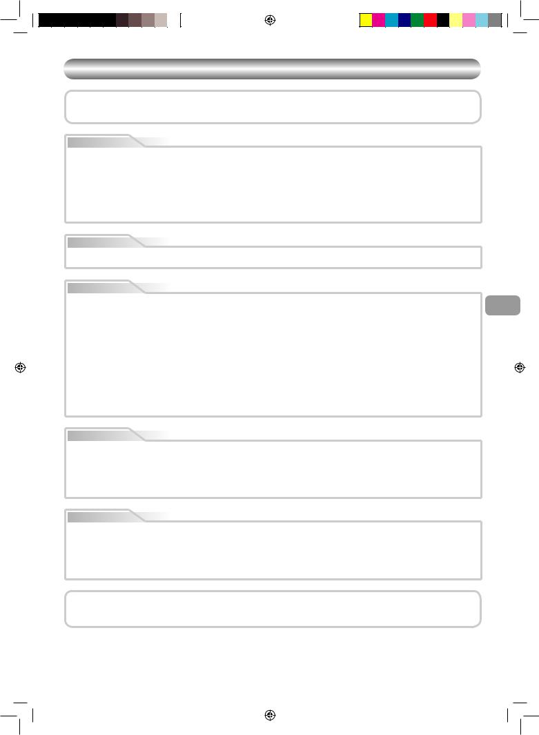
BEZPEČNOSTNÍ OPATŘENÍ
Pro širokou veřejnost
Přívod napětí pro části zařízení pro venkovní použití musí být proveden nejméně pohyblivým přívodem izolovaným polychloroprenem (označení H07RN-F) nebo šňůrou ozn. 245 IEC66 (1,5 mm2 nebo více). (Zařízení musí být instalováno v souladu se státními předpisy o elektroinstalacích.)
UPOZORNĚNÍ |
Instalace nového chladicího média do klimatizačního zařízení |
|
•TOTO KLIMATIZAČNÍ ZAŘÍZENÍ POUŽÍVÁ NOVÉ CHLADICÍ MÉDIUM HFC (R410A), KTERÉ NEPOŠKOZUJE OZÓNOVOU VRSTVU.
Chladicí médium R410A je náchylné ke znečištění takovými látkami, jako jsou například voda, membrány z oxidujících materiálů a oleje, neboť tlak chladiva R410A je přibližně 1,6 násobně vyšší než tlak chladiva R22. Stejně jako začalo být používáno toto nové chladicí médium, došlo také k výměně oleje pro chladicí stroj. Proto v průběhu instalačních prací dbejte na to, aby do chladícího cyklu klimatizačního zařízení, které využívá nové chladivo, nevnikla voda, prach, staré chladicí médium nebo olej chladicího stroje.
Aby se zabránilo smíchání chladiva a oleje chladicího stroje, odlišují se velikosti spojovacích částí na hlavní jednotce od velikostí spojovacích částí tradičního chladiva, a je třeba použít také nářadí jiné velikosti. Pro připojení trubek použijte nový a čistý potrubní materiál s odolností vůči vysokému tlaku, určený pouze pro chladivo R410A, a zajistěte, aby do systému nevnikla voda nebo prach. Kromě toho, nepoužívejte ani žádné stávající potrubí, neboť to nemusí být dostatečně tlakově odolné a může obsahovat nečistoty.
UPOZORNĚNÍ |
Odpojení zařízení z elektrické sítě |
Toto zařízení musí být připojeno k hlavnímu elektrickému rozvodu přes jistič nebo vypínač s mezerou mezi kontakty alespoň 3 mm. Ve vedení pro napájecí zdroj tohoto klimatizačního zařízení musí být použit montážní jistič (25A).
NEBEZPEČÍ
• POUZE PRO KVALIFIKOVANÉ OSOBY. |
CZ |
• PŘED ZAHÁJENÍM ELEKTROPRACÍ VYPNĚTE HLAVNÍ PŘÍVOD ELEKTŘINY. PŘESVĚDČTE SE, ZDA JSOU VŠECHNY VYPÍNAČE NAPÁJENÍ |
|
VYPNUTÉ. V OPAČNÉM PŘÍPADĚ MŮŽE DOJÍT K ÚRAZU ELEKTRICKÝM PROUDEM. |
|
•ZAPOJTE SPRÁVNĚ PŘIPOJOVACÍ KABEL. POKUD JE PŘIPOJOVACÍ KABEL ZAPOJEN ŠPATNĚ, MŮŽE DOJÍT K POŠKOZENÍ ELEKTRICKÝCH ČÁSTÍ.
•PŘED INSTALACÍ SE PŘESVĚDČTE, ZDA NENÍ ZEMNICÍ VODIČ POŠKOZEN NEBO ODPOJEN.
•NEINSTALUJTE V BLÍZKOSTI MÍSTA KONCENTRACE VÝBUŠNÝCH PLYNŮ NEBO PLYNNÝCH VÝPARŮ. PŘI NEDODRŽENÍ TOHOTO POKYNU MŮŽE DOJÍT K POŽÁRU NEBO VÝBUCHU.
•ABY NEDOŠLO K PŘEHŘÁTÍ VNITŘNÍ JEDNOTKY, A TÍM NEBEZPEČÍ POŽÁRU, UMÍSTĚTE JEDNOTKU V DOSTATEČNÉ VZDÁLENOSTI (VÍCE NEŽ 2 M) OD TEPELNÝCH ZDROJŮ, NAPŘ. RADIÁTORŮ, TOPIDEL, KAMEN, SPORÁKŮ APOD.
•PŘI PŘEMISŤOVÁNÍ KLIMATIZAČNÍ JEDNOTKY ZA ÚČELEM INSTALACE V JINÉM MÍSTĚ PEČLIVĚ DBEJTE, ABY SE DO CHLADICÍHO OKRUHU NEDOSTALO URČENÉ CHLADIVO (R410A) S JINOU PLYNNOU LÁTKOU. POKUD DOJDE KE SMÍCHÁNÍ CHLADIVA SE VZDUCHEM NEBO JINÝM PLYNEM, TLAK PLYNU V CHLADICÍM OKRUHU SE ABNORMÁLNĚ ZVÝŠÍ A V DŮSLEDKU TOHO ZPŮSOBÍ ROZTRŽENÍ POTRUBÍ A ZRANĚNÍ OSOB.
•V PŘÍPADĚ, ŽE PŘI INSTALACI VYTÉKÁ Z POTRUBÍ CHLADIVO, IHNED MÍSTNOST VYVĚTREJTE. POKUD SE CHLADIVO POŽÁREM NEBO JINAK OHŘEJE, DOCHÁZÍ K VÝVINU JEDOVATÉHO PLYNU.
VAROVÁNÍ
•Nikdy neprovádějte úpravy jednotky odstraňováním bezpečnostních prvků nebo přemosťováním bezpečnostních spínačů.
•Neprovádějte instalaci na místě, které neunese váhu jednotky.
Při pádu jednotky může dojít ke zranění osob nebo poškození majetku.
•Před prováděním elektroprací připojte k napájecímu přívodu schválenou zástrčku. Také se přesvědčte, zda je zařízení řádně uzemněno.
•Zařízení musí být instalován v souladu se státními předpisy o elektroinstalacích.
Pokud zjistíte jakékoli poškození, jednotku neinstalujte. Ihned kontaktujte svého prodejce zařízení TOSHIBA.
UPOZORNĚNÍ
•Pokud je jednotka před instalací vystavena vodě nebo jiné vlhkosti, může dojít k úrazu elektrickým proudem. Neskladujte ji ve vlhkých sklepních prostorách a nevystavujte ji dešti nebo vodě.
•Po rozbalení jednotky pečlivě zkontrolujte, zda není poškozena.
•Neprovádějte instalaci na místě, které může zvýšit vibrace jednotky. Neprovádějte instalaci na místě, které může zvyšovat hladinu hluku jednotky, nebo kde by hluk a vypouštěný vzduch mohl rušit sousedy.
•Abyste předešli poranění, bud’te opatrní při manipulaci s částmi s ostrými hranami.
•Před instalací jednotky si prosím pečlivě přečtěte tuto instalační příručku. Obsahuje další důležité pokyny pro správnou instalaci.
POŽADAVKY NA OHLÁŠENÍ MÍSTNÍ ELEKTROENERGETICKÉ SPOLEČNOSTI
Před instalací tohoto zařízení je naprosto nezbytné zajistit oznámení instalace místní elektroenergetické společnosti. Pokud se setkáte s problémy, nebo pokud elektroenergetická společnost nebude s instalací souhlasit, servisní společnost přijme příslušná protiopatření.
1
1110251206-CZ.indd 1 |
10/21/09 8:46:02 AM |
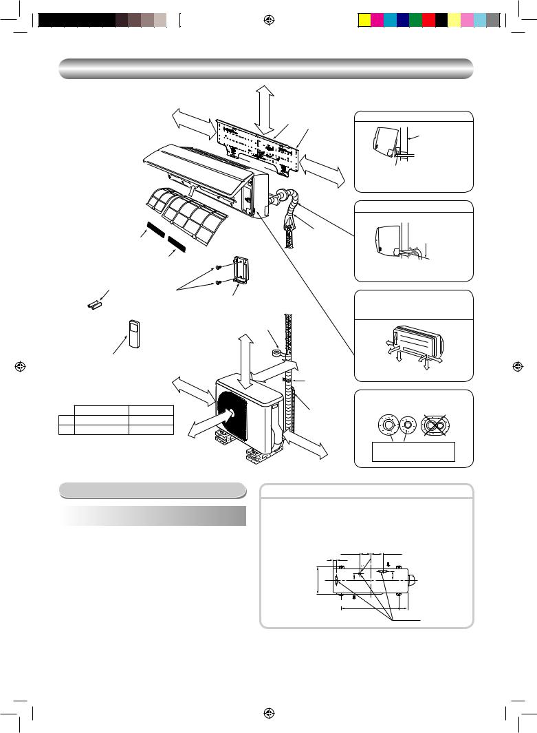
SCHÉMA INSTALACE VNITŘNÍ A VENKOVNÍ JEDNOTKY
170 |
mm |
nebo |
|
|
více |
||
|
|
||
|
|
|
65 mm nebo více
Pro trubky vzadu vlevo a vlevo
Háček
1Instalační deska
Stěna
|
|
|
|
Háč |
170 |
|
|
|
|
|
|
|
ek |
mm |
nebo |
|
|
|
|
|
|
|
|
|
||
|
|
|
|
|
|
|
více |
|
|
|
|
|
|
|
|
|
|
|
|
|
Vz |
|
|
|
|
|
|
|
|
duchový |
|
|
|
|
|
|
|
|
filtr |
|
|
|
|
|
|
(Př |
|
|
|
|
|
|
|
|
|
ipojtek |
|
|
|
|
|
|
|
|
p |
|
|
|
|
|
|
|
|
ř |
|
|
|
|
|
|
|
|
ednímu |
panelu |
|
Ochranná trubka |
|||
|
5 Filtr |
|
|
|
|
|
|
|
|
|
|
.) |
|
|
|
|
|
|
|
6 Filtr |
|
|
|
|
|
|
3 Baterie |
|
8 Vrut s plochou |
|
|
|
|
|
|
|
|
4 Držák dálkového |
|
|
|
|
||
|
|
|
hlavou |
|
|
|
|
|
|
|
|
|
ovládání |
|
|
|
|
|
|
|
|
Vinylová páska |
|
|
|
|
|
|
|
|
Naneste po provedení |
|
|
|
|
|
|
|
|
testu odvodu vody. |
|
|
|
|
|
2 Bezdrátové dálkové ovládání |
|
|
|
|
|
|
|
|
100 |
mm |
|
|
|
|
|
|
|
nebo |
|
|
|
|
|
|
|
|
více |
|
||
|
|
|
|
|
|
||
|
13, 16SAV2 Series |
10SAV2 Series |
|
|
|
|
|
A |
100 |
45 |
|
|
|
|
více |
|
|
|
nebo |
|
|||
|
|
|
|
mm |
|
||
B |
600 |
400 |
|
|
|
||
|
B |
|
|
|
|||
|
|
|
|
|
|
|
|
Poznámka :
•Detailní pohled na příslušenství a montážní díly je na kartě dílů a příslušenství.
•Některé obrázky se mohou na skutečném výrobku lišit.
mm600 vícenebo
|
ce |
|
ví |
mm |
nebo |
|
|
A |
Příchytka |
|
Prodlužovací vypouštěcí hadice (Není k dispozici, dodá
firma provádějící montáž)
600 |
mm |
|
|
|
nebo |
|
|
|
|
více |
|
|
|
|
Vložte mezi vnitřní jednotku a zeď podložku a pro lepší funkci jednotku nakloňte.
Nenechte vypouštěcí hadici uvolnit.
Otvor pro potrubí proved’te s mírným sklonem.
Vypouštěcí hadice musí být vedena se sklonem dolů.
Pomocné potrubí může být připojeno vlevo, vzadu vlevo, vzadu vpravo, vpravo, vespod vpravo, nebo vespod vlevo.
Vpravo |
|
|
Vzadu |
|
|
vpravo |
|
|
Vespod |
Vzadu |
Vlevo |
|
||
vpravo |
vlevo |
Vespod vlevo |
|
|
Trubky s chladivem izolujte jednotlivě, ne společně.
6 mm silná tepelně odolná polyetylenová pěna
Volitelné Doplňky pro Instalaci
Kód |
|
Název dílu |
Množství |
|
dílu |
|
|||
|
|
|
||
|
|
|
||
|
Chladivové potrubí |
|
||
|
Strana kapaliny |
: Ø6,35 mm |
|
|
A |
Strana plynu |
: Ø9,52 mm |
Po |
|
|
(10, 13SKV2 Series) |
jednom |
||
|
|
|||
|
|
: Ø12,70 mm |
|
|
|
|
(16SKV2 Series) |
|
|
|
|
|
||
B |
Izolační materiál pro potrubí |
1 |
||
(polyetylénová pěna, tloušťka 6 mm) |
||||
|
|
|||
|
|
|
|
|
C |
Tmel, PVC pásky |
Po |
||
jednom |
||||
|
|
|
||
|
|
|
|
|
Pozice upevňovacích šroubů venkovní jednotky
•Pokud je pravděpodobné, že bude venkovní jednotka vystavena silnému větru, zajistěte ji pomocí upevňovacích šroubů.
•Použijte ukotvovací šrouby a matice Ø8 mm nebo Ø10 mm.
•Jestliže je třeba vypustit odmraženou vodu, připojte před instalací venkovní jednotky vypouštěcí přípojkao 9 a vodotěsný uzávěro ! na dno nádrže této jednotky.
|
108 mm |
|
|
125 mm |
|
28 mm |
|
mm |
Přívod vzduchu |
|
|
25 |
||
|
|
|
||
|
|
|
|
|
mm |
86 mm |
|
|
102 mm |
320 |
|
|
|
|
Výstup vzduchu
90 mm
600 mm
Výpusť vody
2
1110251206-CZ.indd 2 |
10/21/09 8:46:03 AM |
 Loading...