


Toshiba RAS-3M26GAV-E, RAS-4M23SACV-E, RAS-4M23SAV-E, RAS-4M27GAV-E, RAS-4M27GACV-E INSTALLATION MANUAL
OutdoorInstallation.book Page 0 Tuesday, February 13, 2007 5:58 PM
OUTDOOR UNIT INSTALLATION MANUAL
MANUEL D’INSTALLATION DE L’UNITE EXTERIEURE
EINBAUANLEITUNG FÜR DAS AUSSENGERÄT MANUALE DI INSTALLAZIONE DELL’UNITÀ
ESTERNA
MANUAL DE INSTALACIÓN DE LA UNIDAD EXTERIOR
ǼīȋǼǿȇǿǻǿȅ ǼīȀǹȉǹȈȉǹȈǾȈ ǼȄȍȉǼȇǿȀǾȈ ȂȅȃǹǻǹȈ
MANUAL DE INSTALAÇÃO DA UNIDADE EXTERIOR
INSTALLATIONSANVISNING FÖR
UTOMHUSENHETEN
ИНСТРУКЦИЯ ПО УСТАНОВКE НАРУЖНОГО БЛОКА
AIR CONDITIONER (MULTI-SPLIT TYPE)
|
For general public use |
|
CLIMATISEUR (TYPE BLOCS MULTIPLES) |
Pour utilisation grand public |
|
KLIMAGERÄT (MULTISYSTEM-SPLITGERÄT) |
Für allgemeine Verwendung |
|
CONDIZIONATORE D’ARIA (TIPO MULTI-SPLIT) |
Per l’uso in generale |
|
ACONDICIONADOR DE AIRE (TIPO MÚLTI-SEPARADO) |
Para el uso público general |
|
ȀȁǿȂǹȉǿȈȉǿȀǾ Ȃȅȃǹǻǹ (ȆȅȁȁǹȆȁȅȊ ȉȊȆȅȊ) |
īȚĮ ȖİȞȚțȒ įȘμȩıȚĮ ȤȡȒıȘ |
|
AR CONDICIONADO (TIPO MULTI-SPLIT) |
Para utilização geral |
|
LUFTKONDITIONERING (FLERSPLITTYP) |
För allmän användning |
|
КОНДИЦИОНЕР (МУЛЬТИ-РАЗДЕЛИТЕЛЬНОГО |
Для общего бытового использования |
|
ТИПА) |
|
|
|
|
|
|
Outdoor Unit |
|
|
Unité extérieure |
|
|
Außengerät |
|
|
Unità esterna |
|
|
Unidad exterior |
|
|
ǼȟȦIJİȡȚțȒ μȠȞȐįĮ |
|
|
Unidade exterior |
|
|
Utomhusenhet |
|
|
Наружный блок |
|
|
|
|
|
RAS-4M23SAV-E |
|
|
RAS-4M23SACV-E |
|
|
RAS-3M26GAV-E |
|
|
RAS-4M27GAV-E |
|
|
RAS-4M27GACV-E |
|
Please read this installation manual carefully before installing the air conditioner.
Veuillez lire attentivement ce manuel avant d’installer le climatiseur.
Lesen Sie diese Einbauanleitung sorgfältig durch, bevor Sie das Klimagerät installieren.
Prima di installare il condizionatore d’aria, si consiglia di leggere con attenzione il presente manuale di installazione. Lea este manual de instalación atentamente antes de instalar el acondicionador de aire.
ȆĮȡĮțĮȜȠȪμİ įȚĮȕȐıIJİ ĮȣIJȑȢ IJȚȢ ȠįȘȖȓİȢ İȖțĮIJȐıIJĮıȘȢ ʌȡȠıİțIJȚțȐ ʌȡȚȞ İȖțĮIJĮıIJȒıİIJİ IJȘȞ țȜȚμĮIJȚıIJȚțȒ μȠȞȐįĮ.
Leia atentamente este manual de instalação antes de instalar o ar condicionado. Läs den här installationsanvisningen noga innan du installerar luftkonditioneringen.
Перед установкой кондиционера прочитайте, пожалуйста, внимательно эту инструкцию по установке.
ENGLISH
DEUTSCH FRANÇAIS
ITALIANO
 РУССКИЙ ЯЗЫК SVENSKA PORTUGUÊS ǼȁȁǾȃǿȀǹ ESPAÑOL

OutdoorInstallation.book Page i Tuesday, February 13, 2007 5:58 PM
CONTENTS/SOMMAIRE/INHALT/INDICE/ÍNDICE/ȆǼȇǿǼȋȅȂǼȃǹ/ ÍNDICE/INNEHÅLL/СОДЕРЖАНИЕ
ENGLISH |
|
|
1 |
SAFETY PRECAUTIONS .............................................. |
1 |
2 |
OPTIONAL PARTS, ACCESORIES AND TOOLS ........ |
3 |
3 |
WHICH MODELS CAN BE COMBINED ........................ |
5 |
4 |
INSTALLATION OF OUTDOOR UNIT ........................... |
6 |
5 |
GROUNDING ............................................................... |
12 |
6 |
CHECK AND TEST OPERATION ............................... |
12 |
7 |
USEFUL FUNCTIONS ................................................. |
14 |
FRANÇAIS |
|
|
1 |
MESURES DE SECURITE ............................................ |
1 |
2 |
PIECES EN OPTION, ACCESSOIRES ET OUTILS ..... |
3 |
3 |
QUELS MODELES PEUVENT ETRE COMBINES ....... |
5 |
4 |
SYSTEME DE PRIORITES DE MODE DE |
|
|
FONCTIONNEMENT ..................................................... |
6 |
5 |
MISE A LA TERRE ...................................................... |
12 |
6 |
CONTROLE ET OPERATION D’ESSAI ...................... |
12 |
7 |
FONCTIONS UTILES .................................................. |
14 |
DEUTSCH |
|
|
1 |
SICHERHEITSVORKEHRUNGEN ................................ |
1 |
2 |
SONDERTEILE, SONDERZUBEHÖR UND |
|
|
WERKZEUGE ................................................................ |
3 |
3 |
WELCHE MODELLE KÖNNEN KOMBINIERT |
|
|
WERDEN ....................................................................... |
5 |
4 |
INSTALLATION DES AUSSENGERÄTS ...................... |
6 |
5 |
ERDUNG ..................................................................... |
12 |
6 |
PRÜFUNG UND TESTBETRIEB ................................. |
12 |
7 |
NÜTZLICHE FUNKTIONEN ........................................ |
14 |
ǼȁȁǾȃǿȀǾ |
|
|
1 |
ȆȇȅĭȊȁǹȄǼǿȈ ǹȈĭǹȁǼǿǹȈ ....................................... |
1 |
2 |
ȆȇȅǹǿȇǼȉǿȀǹ ǹȃȉǹȁȁǹȀȉǿȀǹ, ǼȄǹȇȉǾȂǹȉǹ Ȁǹǿ |
|
|
ǼȇīǹȁǼǿǹ ..................................................................... |
3 |
3 |
Ȇȅǿǹ ȂȅȃȉǼȁǹ ȂȆȅȇȅȊȃ ȃǹ ȈȊȃǻȊǹȈȉȅȊȃ ...... |
5 |
4 |
ǼīȀǹȉǹȈȉǹȈǾ ǼȄȍȉǼȇǿȀǾȈ ȂȅȃǹǻǹȈ ................... |
6 |
5 |
īǼǿȍȈǾ ........................................................................ |
12 |
6 |
ǼȁǼīȋȅȈ Ȁǹǿ ǻȅȀǿȂǾ ȁǼǿȉȅȊȇīǿǹȈ ...................... |
12 |
7 |
ȋȇǾȈǿȂǼȈ ȁǼǿȉȅȊȇīǿǼȈ .......................................... |
14 |
PORTUGUÊS |
|
|
1 |
PRECAUÇÕES DE SEGURANÇA ................................ |
1 |
2 |
PEÇAS OPCIONAIS, ACESSÓRIOS E |
|
|
FERRAMENTAS ........................................................... |
3 |
3 |
MODELOS QUE PODEM SER COMBINADOS ............ |
5 |
4 |
INSTALAÇÃO DA UNIDADE EXTERIOR ..................... |
6 |
5 |
LIGAÇÃO À TERRÀ .................................................... |
12 |
6 |
VERIFICAÇÃO E TESTE DA OPERAÇÃO ................. |
12 |
7 |
FUNÇÕES ÚTEIS ....................................................... |
14 |
SVENSKA |
|
|
1 |
SÄKERHETSFÖRESKRIFTER ..................................... |
1 |
2 |
TILLVALSUTRUSTNING, TILLBEHÖR OCH |
|
|
VERKTYG ..................................................................... |
3 |
3 |
VILKA MODELLER SOM GÅR ATT KOMBINERA ....... |
5 |
4 |
INSTALLATION AV UTOMHUSENHETEN ................... |
6 |
5 |
JORDNING .................................................................. |
12 |
6 |
KONTROLL OCH TESTKÖRNING ............................. |
12 |
7 |
PRAKTISKA FUNKTIONER ........................................ |
14 |
ITALIANO |
|
|
1 |
PRECAUZIONI PER LA SICUREZZA ........................... |
1 |
2 |
COMPONENTI OPZIONALI, ACCESSORI E |
|
|
STRUMENTI .................................................................. |
3 |
3 |
QUALI MODELLI É POSSIBILE COMBINARE ............. |
5 |
4 |
INSTALLAZIONE DELL’UNIT À ESTERNA .................. |
6 |
5 |
MESSA A TERRA ........................................................ |
12 |
6 |
CONTROLLI E FUNZIONAMENTO DI PROVA .......... |
12 |
7 |
FUNZIONI UTILI .......................................................... |
14 |
ESPAÑOL |
|
|
1 |
PRECAUCIONES SOBRE SEGURIDAD ...................... |
1 |
2 |
PARTES OPCIONALES, ACCESORIOS Y |
|
|
HERRAMIENTAS .......................................................... |
3 |
3 |
QUÉ MODELOS PUEDEN COMBINARSE ................... |
5 |
4 |
INSTALLATION DE LA UNIDAD EXTERIOR ................ |
6 |
5 |
CONEXIÓN A TIERRA ................................................ |
12 |
6 |
COMPROBACIÓN Y OPERACIÓN DE PRUEBA ....... |
12 |
7 |
FUNCIÓN PRÁCTICA ................................................. |
14 |
РУССКИЙ ЯЗЫК |
|
|
1 |
МЕРЫ ПРЕДОСТОРОЖНОСТИ ................................. |
1 |
2 |
ДОПОЛНИТЕЛЬНЫЕ ЧАСТИ, |
|
|
ПРИНАДЛЕЖНОСТИ И ИНСТРУМЕНТЫ .................. |
3 |
3 |
КОМБИНАЦИЯ КАКИХ МОДЕЛЕЙ ВОЗМОЖНА ...... |
5 |
4 |
УСТАНОВКА НАРУЖНОГО БЛОКА ........................... |
6 |
5 |
ЗАЗЕМЛЕНИЕ ............................................................ |
12 |
6 |
ПРОВЕРКА И ТЕСТОВАЯ ЭКСПЛУАТАЦИЯ .......... |
12 |
7 |
УДОБНАЯ ФУНКЦИЯ ................................................ |
14 |
i

01_OutdoorInstallation_EN.fm Page 1 Friday, March 23, 2007 4:23 PM
IMPORTANT NOTICE
• For details on how to install the indoor units, refer to the installation manual accompanying the indoor units.
1 SAFETY PRECAUTIONS
For general public use
•RAS-4M23SAV-E, RAS-4M23SACV-E
Power supply cord of outdoor unit shall be 1.5 mm2 (H07RN–F or 60245IEC66) polychloroprene sheathed flexible cord.
•RAS-3M26GAV-E, RAS-4M27GAV-E, RAS-4M27GACV-E
Power supply cord of outdoor unit shall be 2.5 mm2 (H07RN–F or 60245IEC66) polychloroprene sheathed flexible cord.
CAUTION
New Refrigerant Air Conditioner Installation
• THIS AIR CONDITIONER ADOPTS THE NEW HFC REFRIGERANT (R410A) WHICH DOES NOT DESTROY OZONE LAYER.
R410A refrigerant is apt to be affected by impurities such as water, oxidizing membrane, and oils because the working pressure of R410A refrigerant is approx. 1.6 times as that of refrigerant R22. Accompanied with the adoption of the new refrigerant, the refrigeration machine oil has also been changed. Therefore, during installation work, be sure that water, dust, former refrigerant, or refrigeration machine oil does not enter the new type refrigerant R410A air conditioner circuit.
To prevent mixing of refrigerant or refrigerating machine oil, the sizes of connecting sections of charging port on main unit and installation tools are different from those of the conventional refrigerant units. Accordingly, special tools are required for the new refrigerant (R410A) units as shown on page 4. For connecting pipes, use new and clean piping materials with high pressure fittings made for R410A only, so that water and/or dust does not enter. Moreover, do not use the existing piping because there are some problems with pressure fittings and possible impurities in existing piping.
ENGLISH
CAUTION
TO DISCONNECT THE APPLIANCE FROM THE MAIN POWER SUPPLY
Disconnection from the supply mains:
The means for disconnection must be incorporated in the fixed wiring in accordance with the wiring rules.
1 |
EN |

OutdoorInstallation.book Page 2 Tuesday, February 13, 2007 5:58 PM
DANGER
•FOR USE BY QUALIFIED PERSONS ONLY.
•TURN OFF MAIN POWER SUPPLY BEFORE ATTEMPTING ANY ELECTRICAL WORK. MAKE SURE ALL POWER SWITCHES ARE OFF. FAILURE TO DO SO MAY CAUSE ELECTRIC SHOCK.
•CORRECTLY CONNECT THE CONNECTING CABLE. IF THE CONNECTING CABLE IS INCORRECTLY CONNECTED, ELECTRIC PARTS MAY BE DAMAGED.
•CHECK THAT THE EARTH WIRE IS NOT BROKEN OR DISCONNECTED BEFORE INSTALLATION. FAILURE TO DO SO MAY CAUSE ELECTRIC SHOCK.
•DO NOT INSTALL THE UNIT IN A PLACE WHERE INFLAMMABLE GAS CAN LEAK. A FIRE CAN RESULT IF INFLAMMABLE GAS ACCUMULATES AROUND THE UNIT.
•TO PREVENT THE INDOOR UNIT FROM OVERHEATING AND CAUSING A FIRE HAZARD, PLACE THE UNIT WELL AWAY (MORE THAN 2 M) FROM HEAT SOURCES SUCH AS RADIATORS, HEAT REGISTORS, FURNACE, STOVES, ETC.
•WHEN MOVING THE AIR-CONDITIONER FOR INSTALLATION TO ANOTHER PLACE, BE VERY CAREFUL NOT TO ALLOW THE SPECIFIED REFRIGERANT (R410A) TO BECOME MIXED WITH ANY OTHER GASEOUS BODY INTO THE REFRIGERATION CIRCUIT. IF AIR OR ANY OTHER GAS MIXES WITH THE REFRIGERANT, THE GAS PRESSURE IN THE REFRIGERATION CIRCUIT WILL BECOME ABNORMALLY HIGH AND IT MAY RESULT IN THE PIPE BURSTING OR PERSONNEL INJURIES.
•IN THE EVENT THAT THE REFRIGERANT GAS LEAKS OUT OF THE PIPE DURING THE INSTALLATION WORK, IMMEDIATELY LET FRESH AIR INTO THE ROOM. IF THE REFRIGERANT GAS IS HEATED, POISONOUS GAS MAY RESULT.
•WHEN INSTALLING THE AIR CONDITIONER UNIT, MAKE SURE THAT THE REFRIGERANT PIPE IS CONNECTED SECURELY BEFORE THE COMPRESSOR IS OPERATED. IF THE COMPRESSOR IS OPERATED WITH THE REFRIGERANT PIPE UNCONNECTED, WHICH MEANS THAT THE SERVICE VALVE WILL BE LEFT OPEN, AIR, ETC. WILL BE SUCKED IN, CAUSING THE PRESSURE INSIDE THE REFRIGERATION CYCLE TO RISE TO AN ABNORMALLY HIGH LEVEL, AND POSSIBLY RESULTING IN RUPTURE, INJURY, ETC.
•WHEN CARRYING OUT THE PUMP-DOWN WORK, SHUT DOWN THE COMPRESSOR BEFORE DISCONNECTING THE REFRIGERANT PIPE. DISCONNECTING THE REFRIGERANT PIPE WITH THE SERVICE VALVE LEFT OPEN AND WITH THE COMPRESSOR STILL OPERATING WILL CAUSE AIR, ETC. TO BE SUCKED IN, RAISING THE PRESSURE INSIDE THE REFRIGERATION CYCLE TO AN ABNORMALLY HIGH LEVEL, AND POSSIBLY RESULTING IN RUPTURING, INJURY, ETC.
WARNING
•Never modify this unit by removing any of the safety guards.
•The installation of the air conditioner must be positioned in a location that can sufficiently support its weight. Failure to do so may result in unit damage and human injury.
•Appliance shall be installed in accordance with national wiring regulations.
•If you detect any damage, do not install the unit. Contact your Toshiba dealer immediately.
CAUTION
•Exposure of unit to water or other moisture before installation may result in an electrical short. Do not store in a wet basement or expose to rain or water.
•After unpacking the unit, examine it carefully for any damage.
•Do not install in a place that can increase the vibration of the unit. Do not install in a place that can amplify the noise level of the unit or where noise or discharged air might disturb neighbors.
•To avoid personal injury, be careful when handling parts with sharp edges.
•Please read this installation manual carefully before installing the unit. It contains further important instructions necessary for proper installation.
•Wear work gloves when carrying out the installation work or repairs. Contact with parts, etc. may cause injury if the work or repairs are conducted without wearing gloves.
EN |
2 |
OutdoorInstallation.book Page 3 Tuesday, February 13, 2007 5:58 PM
2 OPTIONAL PARTS, ACCESORIES AND TOOLS
Optional Installation Parts
Part name |
|
Specifications |
|
Q’ty |
|
|
Indoor unit name |
Liquid side |
Gas side |
|
|
Refrigerant piping*1 |
(Abbreviation) |
(Outer diameter) |
(Outer diameter) |
1 ea. |
|
|
|
|
|||
10, 13 |
6.35 mm |
9.52 mm |
|||
|
|
||||
|
|
|
|
|
|
|
16 |
6.35 mm |
12.7 mm |
|
|
|
|
|
|
|
|
Putty, PVC tapes |
|
|
|
1 ea. |
|
|
|
|
|
|
*1 Refrigerant piping covered with insulating material (polyethylene form, 6 mm thick).
*In case the piping is installed above the ceiling, it shall be covered with thicker insulating material (polyethylene form, 10 mm thick).
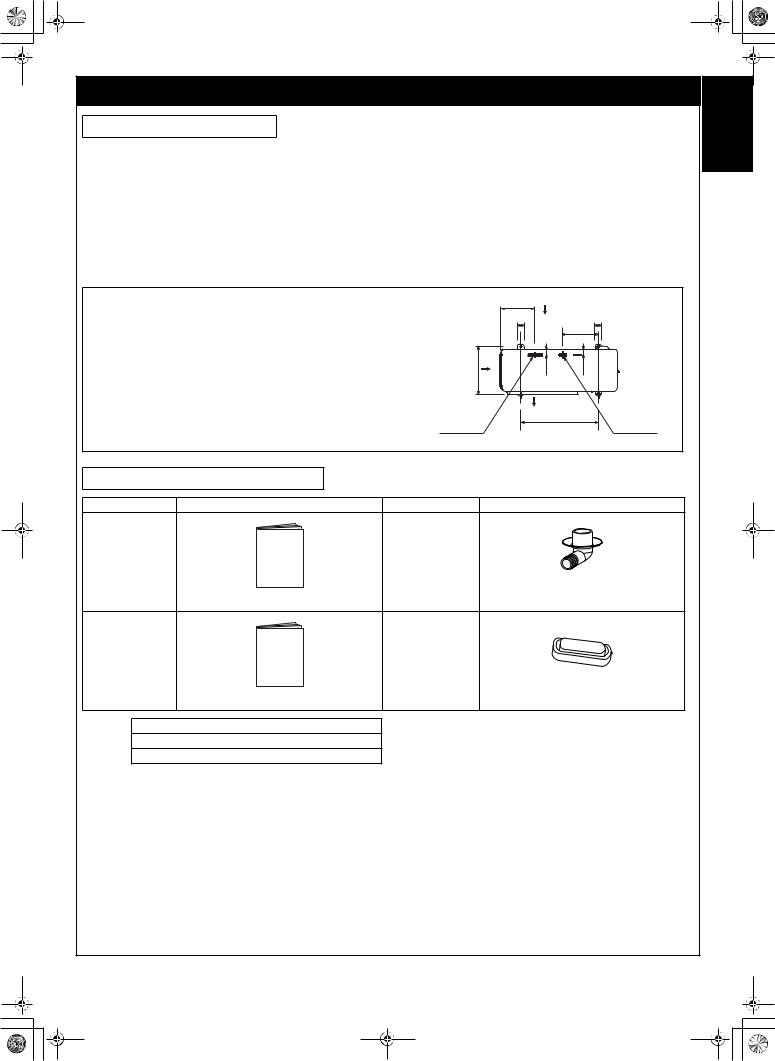
Attachment bolt arrangement of outdoor unit
• |
Secure the outdoor unit with the attachment bolts and nuts if the unit |
259 |
Suction side |
|
|
||||
|
is likely to be exposed to a strong wind. |
50 |
|
50 |
|
|
|
280 |
|
• |
Use I8 mm or I10 mm anchor bolts and nuts. |
|
|
|
|
|
|
||
• |
If it is necessary to drain the defrost water, attach drain nipple to the |
|
|
|
|
base plate of the outdoor unit before installing it. |
365 |
42.5 |
40 |
|
|
|||
|
|
|
Diffuser |
|
|
|
Elongated drain |
600 |
Drain hole |
|
|
hole |
||
|
|
(d) |
|
(c) |
Accessory and Installation Parts
Part No. |
Part name (Q’ty) |
Part No. |
Part name (Q’ty) |
a |
|
c |
|
|
Drain nipple x 1 |
|
Outdoor unit installation manual x 1 |
(Heat pump models only) |
b |
|
d |
|
|
Water-proof rubber cap x 1 |
|
Specifications x 1 |
(Heat pump models only) |
|
|
|
Others |
Name |
|
Important information and warning
B/W strips (Energy efficiency labels)
ENGLISH
3 |
EN |
OutdoorInstallation.book Page 4 Tuesday, February 13, 2007 5:58 PM
Installation/Service Tools
Changes in the product and components
In air conditioners using R410A, in order to prevent any other refrigerant from being accidentally charged, the service port diameter size of the outdoor unit control valve (3 way valve) has been changed. (1/2 UNF 20 threads per inch)
•In order to increase the pressure resisting strength of the refrigerant piping, flare processing diameter and opposing flare nuts sizes have been changed. (for copper pipes with nominal dimensions 1/2 and 5/8)
New tools for R410A
New tools for R410A |
|
|
Applicable to R22 model |
Changes |
||||||||||||||||
|
|
|
|
|
|
|
|
|
|
|
|
|
|
|
|
|
|
|
|
|
Gauge manifold |
|
|
|
|
|
|
|
|
|
|
|
|
|
|
|
|
|
|
|
As the working pressure is high, it is impossible to measure |
|
|
|
|
|
|
|
|
|
|
|
|
|
|
|
|
|
|
|
|
the working pressure using conventional gauges. In order to |
|
|
|
|
|
|
|
|
|
|
|
|
|
|
|
|
|
|
|
|
|
|
|
|
|
|
|
|
|
|
|
|
|
|
|
|
|
|
|
|
|
prevent any other refrigerant from being charged, the port |
|
|
|
|
|
|
|
|
|
|
|
|
|
|
|
|
|
|
|
|
|
|
|
|
|
|
|
|
|
|
|
|
|
|
|
|
|
|
|
|
|
diameters have been changed. |
|
|
|
|
|
|
|
|
|
|
|
|
|
|
|
|
|
|
|
|
|
Charge hose |
|
|
|
|
|
|
|
|
|
|
|
|
|
|
|
|
|
|
|
In order to increase pressure resisting strength, hose |
|
|
|
|
|
|
|
|
|
|
|
|
|
|
|
|
|
|
|
|
materials and port sizes have been changed (to 1/2 UNF 20 |
|
|
|
|
|
|
|
|
|
|
|
|
|
|
|
|
|
|
|
|
|
|
|
|
|
|
|
|
|
|
|
|
|
|
|
|
|
|
|
|
|
threads per inch). |
|
|
|
|
|
|
|
|
|
|
|
|
|
|
|
|
|
|
|
|
When purchasing a charge hose, be sure to confirm the |
|
|
|
|
|
|
|
|
|
|
|
|
|
|
|
|
|
|
|
|
|
|
|
|
|
|
|
|
|
|
|
|
|
|
|
|
|
|
|
|
|
|
|
|
|
|
|
|
|
|
|
|
|
|
|
|
|
|
|
|
|
|
port size. |
|
|
|
|
|
|
|
|
|
|
|
|
|
|
|
|
|
|
|
|
|
Electronic balance for refrigerant |
|
|
|
|
|
|
|
|
|
|
|
|
|
|
|
|
|
|
|
As working pressure is high and gasification speed is fast, it |
|
|
|
|
|
|
|
|
|
|
|
|
|
|
|
|
|
|
|
||
charging |
|
|
|
|
|
|
|
|
|
|
|
|
|
|
|
|
|
|
|
is difficult to read the indicated value by means of charging |
|
|
|
|
|
|
|
|
|
|
|
|
|
|
|
|
|
|
|
||
|
|
|
|
|
|
|
|
|
|
|
|
|
|
|
|
|
|
|
|
cylinder, as air bubbles occur. |
|
|
|
|
|
|
|
|
|
|
|
|
|
|
|
|
|
|
|
|
|
|
|
|
|
|
|
|
|
|
|
|
|
|
|
|
|
|
|
|
|
|
Torque wrench |
|
|
|
|
|
|
|
|
|
|
|
|
|
|
|
|
|
|
|
The size of opposing flare nuts have been increased. |
|
|
|
|
|
|
|
|
|
|
|
|
|
|
|
|
|
|
|
||
(nominal dia. 1/2, 5/8) |
|
|
|
|
|
|
|
|
|
|
|
|
|
|
|
|
|
|
|
Incidentally, a common wrench is used for nominal |
|
|
|
|
|
|
|
|
|
|
|
|
|
|
|
|
|
|
|
||
|
|
|
|
|
|
|
|
|
|
|
|
|
|
|
|
|
|
|
|
diameters 1/4 and 3/8. |
|
|
|
|
|
|
|
|
|
|
|
|
|
|
|
|
|
|
|
|
|
|
|
|
|
|
|
|
|
|
|
|
|
|
|
|
|
|
|
|
|
|
Flare tool (clutch type) |
|
|
|
|
|
|
|
|
|
|
|
|
|
|
|
|
|
|
|
By increasing the clamp bar’s receiving hole size, strength |
|
|
|
|
|
|
|
|
|
|
|
|
|
|
|
|
|
|
|
|
of spring in the tool has been improved. |
|
|
|
|
|
|
|
|
|
|
|
|
|
|
|
|
|
|
|
|
|
|
|
|
|
|
|
|
|
|
|
|
|
|
|
|
|
|
|
|
|
|
|
|
|
|
|
|
|
|
|
|
|
|
|
|
|
|
|
|
|
|
|
|
|
|
|
|
|
|
|
|
|
|
|
|
|
|
|
|
|
|
|
|
Gauge for projection adjustment |
|
|
— |
|
|
|
|
|
|
|
|
|
|
|
|
|
|
Used when flare is made by using conventional flare tool. |
||
|
|
|
|
|
|
|
|
|
|
|
|
|
|
|
|
|
|
|
|
|
Vacuum pump adapter |
|
|
|
|
|
|
|
|
|
|
|
|
|
|
|
|
|
|
|
Connected to conventional vacuum pump. It is necessary to |
|
|
|
|
|
|
|
|
|
|
|
|
|
|
|
|
|
|
|
|
use an adapter to prevent vacuum pump oil from flowing |
|
|
|
|
|
|
|
|
|
|
|
|
|
|
|
|
|
|
|
|
back into the charge hose. The charge hose connecting |
|
|
|
|
|
|
|
|
|
|
|
|
|
|
|
|
|
|
|
|
|
|
|
|
|
|
|
|
|
|
|
|
|
|
|
|
|
|
|
|
|
|
|
|
|
|
|
|
|
|
|
|
|
|
|
|
|
|
|
|
|
|
part has two ports — one is for conventional refrigerant (7/ |
|
|
|
|
|
|
|
|
|
|
|
|
|
|
|
|
|
|
|
|
16 UNF 20 threads per inch) and the other is for R410A. If |
|
|
|
|
|
|
|
|
|
|
|
|
|
|
|
|
|
|
|
|
|
|
|
|
|
|
|
|
|
|
|
|
|
|
|
|
|
|
|
|
|
the vacuum pump oil (mineral) mixes with R410A a sludge |
|
|
|
|
|
|
|
|
|
|
|
|
|
|
|
|
|
|
|
|
may occur and damage the equipment. |
|
|
|
|
|
|
|
|
|
|
|
|
|
|
|
|
|
|
|
|
|
Gas leakage detector |
|
|
|
|
|
|
|
|
|
|
|
|
|
|
|
|
|
|
|
Exclusive for HFC refrigerant. |
|
|
|
|
|
|
|
|
|
|
|
|
|
|
|
|
|
|
|
|
|
|
|
|
|
|
|
|
|
|
|
|
|
|
|
|
|
|
|
|
|
|
|
|
|
|
|
|
|
|
|
|
|
|
|
|
|
|
|
|
|
|
|
•Incidentally, the “refrigerant cylinder” comes with the refrigerant designation (R410A) and protector coating in the U.S’s ARI specified rose color (ARI color code: PMS 507).
•Also, the “charge port and packing for refrigerant cylinder” requires 1/2 UNF 20 threads per inch corresponding to the charge hose’s port size.
EN |
4 |

OutdoorInstallation.book Page 5 Tuesday, February 13, 2007 5:58 PM
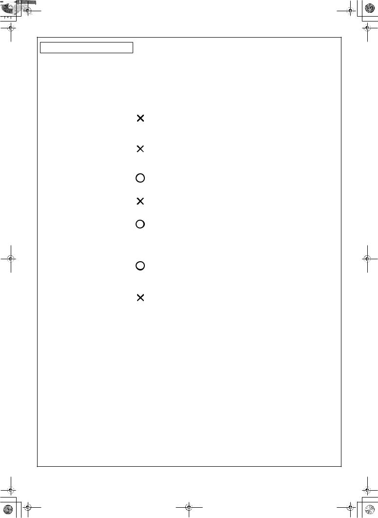
3 WHICH MODELS CAN BE COMBINED
Table of models that can be connected
 : Can be connected.
  : Cannot be connected.
|
|
|
|
|
|
|
4-way Air |
|
|
|
|
High Wall Type |
|
Slim Duct |
Discharge |
||
|
|
|
|
Type |
Cassette |
|||
|
|
|
|
|
|
|||
|
|
|
|
|
|
|
Type |
|
|
|
With air purifying unit |
|
Without air purifying unit |
|
|||
Indoor unit |
|
DAISEIKAI 2 |
DAISEIKAI 3 |
|
|
|
|
|
specification |
16-class |
RAS- |
RAS- |
RAS- |
RAS- |
RAS- |
RAS- |
|
|
B16GKVP-E B16SKVP-E M16GKV-E |
M16SKV-E |
M16GDV-E |
M16SMUV-E |
||||
|
|
|||||||
Heat |
13-class |
RAS- |
RAS- |
RAS- |
RAS- |
RAS- |
RAS- |
|
pump |
B13GKVP-E |
B13SKVP-E M13GKV-E |
M13SKV-E |
M13GDV-E |
M13SMUV-E |
|||
|
||||||||
|
10-class |
RAS- |
RAS- |
RAS- |
RAS- |
RAS- |
RAS- |
|
|
B10GKVP-E B10SKVP-E M10GKV-E |
M10SKV-E |
M10GDV-E |
M10SMUV-E |
||||
|
|
|||||||
|
RAS- |
|
|
|
|
|
|
|
Outdoor unit |
4M23SAV-E |
|
|
|
|
|
|
|
RAS- |
|
|
|
|
|
|
||
for |
|
|
|
|
|
|
||
3M26GAV-E |
|
|
|
|
|
|
||
combination |
|
|
|
|
|
|
||
RAS- |
|
|
|
|
|
|
||
|
|
|
|
|
|
|
||
|
4M27GAV-E |
|
|
|
|
|
|
|
|
|
|
|
|
|
|
4-way Air |
|
|
|
|
High Wall Type |
|
Slim Duct |
Discharge |
||
|
|
|
|
Type |
Cassette |
|||
|
|
|
|
|
|
|||
|
|
|
|
|
|
|
Type |
|
|
|
With air purifying unit |
|
Without air purifying unit |
|
|||
Indoor unit |
|
DAISEIKAI 2 |
DAISEIKAI 3 |
|
|
|
|
|
specification |
16-class |
RAS- |
RAS- |
RAS- |
RAS- |
RAS- |
RAS- |
|
Cooling- |
M16GKCVP-E |
M16SKCVP-E M16GKCV-E |
M16SKCV-E M16GDCV-E |
M16SMUCV-E |
||||
|
||||||||
only |
13-class |
RAS- |
RAS- |
RAS- |
RAS- |
RAS- |
RAS- |
|
|
M13GKCVP-E |
M13SKCVP-E M13GKCV-E |
M13SKCV-E M13GDCV-E |
M13SMUCV-E |
||||
|
|
|||||||
|
10-class |
RAS- |
RAS- |
RAS- |
RAS- |
RAS- |
RAS- |
|
|
M10GKCVP-E |
M10SKCVP-E |
M10GKCV-E |
M10SKCV-E |
M10GDCV-E |
M10SMUCV-E |
||
|
|
|||||||
Outdoor unit |
RAS- |
|
|
|
|
|
|
|
4M23SACV-E |
|
|
|
|
|
|
||
for |
|
|
|
|
|
|
||
RAS- |
|
|
|
|
|
|
||
combination |
|
|
|
|
|
|
||
4M27GACV-E |
|
|
|
|
|
|
||
|
|
|
|
|
|
|
||
NOTES |
|
|
|
|
|
|
|
|
A 1-room connection is not an option for the indoor units (you cannot connect only one indoor unit). A 2-room or more connection must always be used for the indoor units (you must connect at least two indoor units).
ENGLISH
5 |
EN |

OutdoorInstallation.book Page 6 Tuesday, February 13, 2007 5:58 PM
4 INSTALLATION OF OUTDOOR UNIT
Installation Location
•A place which provides enough space around the outdoor unit as shown in the diagram.
•A place which can bear the weight of the outdoor unit and does not allow an increase in noise level and vibration.
•A place where the operation noise and discharged air do not disturb neighbors.
•A place which is not exposed to a strong wind.
•A place free of combustible gases.
•A place which does not block a passageway.
•When the outdoor unit is to be installed in an elevated position, be sure to secure its feet.
•Piping connections to the outdoor unit should be arranged in the sequence A, then B, C, D, starting from the bottom. (For each piping connection, the gas pipe is on the bottom and the liquid pipe on top.)
•When multiple indoor units are to be connected to the outdoor unit, make sure the ends of the pipes and wires from each indoor unit are connected to the outdoor unit correctly. (Problems caused by indoor units being connected to the outdoor unit incorrectly are very common in multiple-unit installations.)
•The length and height differences of the connecting pipes between the indoor and outdoor units must be within the ranges indicated below.
Allowable piping length and height difference
NOTE: For installation, at least 3 sides should be kept away from obstacles (walls).
600 mm or more
100 mm or more from wall
100 mm or more from wall
600 mm or more from wall
600 mm or more
As shown in the figure, hang power cord and connecting cable downward.
|
Item |
|
Piping length |
|
|
|
Outdoor unit |
Minimum for 1 unit |
Maximum for 1 unit |
Maximum for |
Maximum for |
Height difference |
|
total of 3 units |
total of 4 units |
|
||||
|
|
|
|
|||
RAS-4M23SAV-E |
|
|
|
— |
60 m*1 |
|
RAS-4M23SACV-E |
|
|
|
|
||
|
|
|
|
|
|
|
RAS-3M26GAV-E |
2 m |
25 m |
|
50 m |
— |
15 m |
RAS-4M27GAV-E |
|
|
|
— |
70 m*2 |
|
RAS-4M27GACV-E |
|
|
|
|
||
|
|
|
|
|
|
|
*The outdoor unit should not be installed with one indoor unit only. Be sure the (outdoor) unit is installed with at least two indoor units.
*1 If the total piping length for the 4M23 is 40 m or more, add an extra 20 g/m of refrigerant.
*2 If a 4-way air discharge cassette type is connected to the 4M27, the maximum piping length is 50 m.
•If the outdoor unit is to be mounted on a wall, make sure the platform supporting it is sturdy enough.
The platform should be designed and manufactured to maintain its strength over a long period of time, and sufficient consideration should be given to ensuring that the outdoor unit will not fall.
•When the outdoor unit is to be mounted high on a wall, take particular care to ensure that parts do not fall, and that the installer is protected.
•When doing installation work at ground level, it is usual to make wiring and pipe connections to the indoor units, first, and then to make connections to the outdoor unit.
However, if outdoor work is difficult it is possible, instead, to make changes to the procedure.
For example, by making adjustments to the wiring and piping lengths on the inside (rather than the outside).
•A place where the drain water does not cause any problems.
EN |
6 |

OutdoorInstallation.book Page 7 Tuesday, February 13, 2007 5:58 PM
CAUTION
1.Install the outdoor unit in a location where there are no obstructions near its air intake or air outlet.
2.When the outdoor unit is installed in a place that is always exposed to strong winds like on the coast or on a high story of a building, secure the normal fan operation using a duct or a wind shield.
3.Especially in windy areas, install the unit to prevent the admission of wind.
4.Installation in the following places may result in trouble. Do not install the unit in such places.
•A place full of machine oil.
•A saline-place such as the coast. 
•A place full of sulfide gas. 


• A place where high-frequency waves are likely to be generated, such |
Strong |
as from audio equipment, welders, and medical equipment. |
wind |
|
Draining the water (heat pump models only)
A hole is provided on the base plate of the outdoor unit to ensure that the defrost water produced during heating operations is drained
off efficiently.
When the outdoor unit is to be installed in an area with a moderate climate
•Allow the water in the outdoor unit to drip onto the ground.
•If a centralized drain is required, which is the case when the unit is installed on a balcony or against a wall, follow the steps below.
•When a drain pipe is to be used to drain the water
•Use a drain pan to catch the defrost water, and drain the pan.
•Use a pipe made of hard PVC with a nominal diameter of 25A (25 mm inside diameter) for the drain pipe.
Direction of air
 blown out
Drain port
Outline of |
Outline of outdoor |
drain pan |
unit |
Tips when using a drain pan and elbow |
|
|
|
|
|
|
|
|
|
|
|
• |
When using a drain pan, check its dimensions before deciding where the |
Outdoor unit |
Drain pan |
|
|
|
|||||
|
outdoor unit is to be installed. |
|
|
|
|
|
|
|
|
|
|
• |
When the elbow supplied is to be used, be advised that its dimensions are as |
|
|
|
|
Elbow (with a 40 mm |
|||||
|
shown in the figure. Ensure that the foundation does not protrude beyond |
|
|
|
|
outside diameter) |
|||||
|
|
|
|
|
|
|
|
|
|
|
|
|
where the elbow and the part of the hose connected to it are to be installed. |
|
|
30 |
|
|
|
|
|||
|
|
|
|
|
80 |
|
|
||||
|
|
|
|
|
|
|
|
|
|
|
|
|
|
|
|
|
|
|
|
|
|
|
|
|
|
|
|
|
|
|
|
|
|
|
|
|
|
|
|
|
|
|
|
|
|
|
|
|
|
|
Foundation |
|
58 |
|
|
|
|||
|
|
|
|
|
|
|
|||||
|
|
|
|
|
|
|
|
||||
|
|
|
|
|
|
|
|
|
|
|
|
•When draining off the water using a drain nipple
When a drain hose is to be used to drain the water, install the drain nipple and water-proofing rubber cap shown in the figure, and use a commercially available drain hose (16 mm inside diameter). Tightly seal the knock-out holes and screw/ thread areas using a silicon adhesive, etc. to ensure that there is no water drippage. Under some conditions, condensation may form on the base plate and drip down. When all the defrost water is to be drained off using a centralized drain, use the drain pan.
When the outdoor unit is to be installed in an area with a snowy or cold climate
•Allow the water in the outdoor unit to drip onto the ground. (Do not use a hose to drain off the water.)
•The drain water may freeze inside the base plate at below freezing outside air temperatures so use a screwdriver or other tool to open the knock-out holes in the base plate.
The water will drain more efficiently when the knock-out holes are opened. (Use a screwdriver or other tool to pull out the knock-out pieces.)
d Water-proofing rubber cap
c Drain nipple
Knock-out holes
ENGLISH
7 |
EN |
OutdoorInstallation.book Page 8 Tuesday, February 13, 2007 5:58 PM
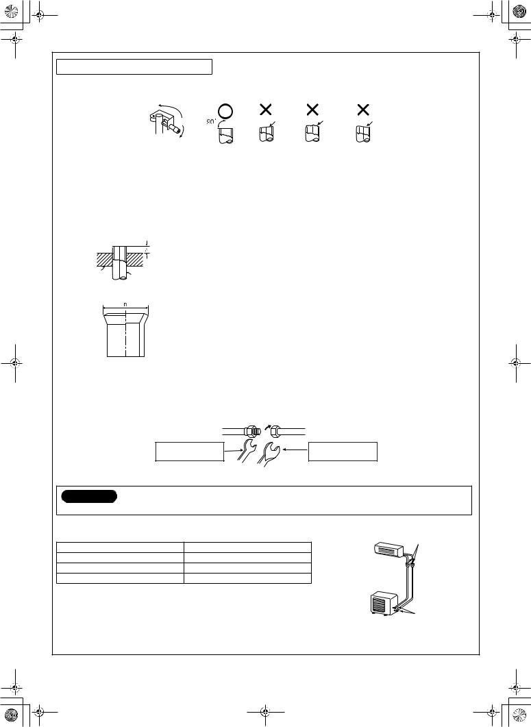
Refrigerant Piping Connection
Flaring
1.Cut the pipe with a pipe cutter.
|
Obliquity |
Roughness |
Warp |
|
|
|
|
|
|
|
|
2.Insert a flare nut into the pipe, and flare the pipe.
• Projection margin in flaring: A (Unit: mm)
Rigid (Clutch type)
Outer diameter of copper pipe |
R410A tool used |
Conventional tool used |
|
|
|
6.35 |
0 to 0.5 |
1.0 to 1.5 |
|
|
|
9.52 |
0 to 0.5 |
1.0 to 1.5 |
|
|
|
12.7 |
0 to 0.5 |
1.0 to 1.5 |
|
|
|
Die |
Pipe |
|
3.Flaring size: B (Unit: mm)
Imperial (Wing nut type)
Outer diameter of copper pipe |
|
R410A |
|
|
|
|
|
6.35 |
|
1.5 to 2.0 |
|
|
|
|
|
9.52 |
|
1.5 to 2.0 |
|
|
|
|
|
12.7 |
|
2.0 to 2.5 |
|
|
|
|
|
|
|
|
|
Outer diameter of copper pipe |
|
B –0.4+0 |
|
|
|
|
|
|
R410A |
|
R22 |
|
|
|
|
6.35 |
9.1 |
|
9.0 |
|
|
|
|
9.52 |
13.2 |
|
13.0 |
|
|
|
|
12.7 |
16.6 |
|
16.2 |
|
|
|
|
•In case of flaring for R410A with the conventional flare tool, pull it out approx. 0.5 mm more than that of R22 to adjust the specified flare size. The copper pipe gauge is useful for adjusting projection margin size.
Tighten the connection
Align the centers of the connecting pipes and tighten the flare nut as much as possible with your fingers. Then tighten the nut with a wrench and torque wrench as shown in the figure.
Half union |
Flare nut |
Externally threaded side |
Internally threaded side |
Use a wrench to secure. |
Use a torque wrench to tighten. |
CAUTION
• Do not apply excessive force. Otherwise, the nut may break.
|
(Unit: N·m) |
Flare at indoor |
Outer diameter of copper pipe |
Tightening torque |
unit side |
I6.35 mm |
14 to 18 (1.4 to 1.8 kgf·m) |
|
I9.52 mm |
33 to 42 (3.3 to 4.2 kgf·m) |
|
I12.7 mm |
50 to 62 (5.0 to 6.2 kgf·m) |
|
Flare at outdoor unit side
EN |
8 |
 Loading...