


INSTALLATION MANUAL
AIR CONDITIONER (SPLIT TYPE)
Indoor unit
RAS-18, 24SKP-ES
Outdoor unit
RAS-18, 24SA-ES
ENGLISH
ESPAÑOL
FRANÇAIS
ITALIANO
DEUTSCH PORTUGUÊS POLSKI
ČESKY
PУCСКИЙ
HRVATSKI
MAGYAR
TÜRKÇE NEDERLANDS
ΕΛΛΗΝΙΚΑ
SVENSKA
SUOMI
NORSK
DANSK
ROMÂNĂ
БЪЛГАРСКИ
EESTI
LATVISKI
SLOVENČINA
SLOVENŠČINA
1110651129
Toshiba 1110651129 (CV_F).indd 1 |
2/4/09 11:57:35 AM |

EN |
CONTENTS |
|
ES |
CONTENIDOS |
|
|
FR |
SOMMAIRE |
|
PRECAUTIONS FOR SAFETY.................................................... |
1 |
PRECAUCIONES SOBRE SEGURIDAD .................................... |
1 |
|
MESURES DE SÉCURITÉ........................................................... |
1 |
|||
INSTALLATION DIAGRAM OF INDOOR AND |
|
DIAGRAMA DE INSTALACIÓN DE LA UNIDAD |
|
|
PLAN D’INSTALLATION DES UNITÉS INTÉRIEURE ET |
|
|||
OUTDOOR UNITS ....................................................................... |
2 |
INTERIOR Y EXTERIOR.............................................................. |
2 |
|
EXTÉRIEURE............................................................................... |
2 |
|||
Optional Installation Parts ....................................................... |
2 |
Piezas de Instalación Opcional .............................................. |
2 |
|
Pièces d’Installation en Option ............................................... |
2 |
|||
INDOOR UNIT.............................................................................. |
3 |
UNIDAD INTERIOR ..................................................................... |
3 |
UNITÉ INTÉRIEURE .................................................................... |
3 |
||||
Installation Place ..................................................................... |
3 |
Lugar de Instalación ................................................................ |
3 |
|
Endroit d’Installation ................................................................ |
3 |
|||
Cutting a Hole and Mounting Installation Plate ....................... |
3 |
Corte de un Orificio y Montaje de la Placa de Instalación ...... |
3 |
|
Ouverture du Trou et Montage de la Plaque d’Installation ..... |
3 |
|||
Wiring Connection ................................................................... |
4 |
Conexión de Cables ................................................................ |
4 |
|
Connexion des Câbles ............................................................ |
4 |
|||
Piping and Drain Hose Installation .......................................... |
4 |
Instalación la Tubería y el Tubo de Desagüe ......................... |
4 |
|
Installation de la Conduite et du Tuyau de Purge .................. |
4 |
|||
Indoor Unit Fixing .................................................................... |
5 |
Instalación de la Unidad Interior.............................................. |
5 |
|
Installation de l’Unité Intérieure ............................................... |
5 |
|||
Drainage.................................................................................. |
5 |
Drenaje ................................................................................... |
5 |
|
Drainage ................................................................................. |
5 |
|||
OUTDOOR UNIT.......................................................................... |
5 |
UNIDAD EXTERIOR .................................................................... |
5 |
UNITÉ EXTÉRIEURE................................................................... |
5 |
||||
Installation Place ..................................................................... |
5 |
Lugar de Instalación ................................................................ |
5 |
|
Endroit d’Installation ................................................................ |
5 |
|||
Refrigerant Piping Connection ................................................ |
6 |
Conexión de la Tubería Refrigerante ...................................... |
6 |
|
Connexion du Tuyau Réfrigérant ............................................ |
6 |
|||
Evacuating .............................................................................. |
6 |
Evacuación ............................................................................. |
6 |
|
Evacuation .............................................................................. |
6 |
|||
Wiring Connection ................................................................... |
6 |
Conexión de Cables ................................................................ |
6 |
|
Connexion des Câbles ............................................................ |
6 |
|||
Electrical Work ........................................................................ |
6 |
Trabajo Eléctrico .................................................................... |
6 |
|
Travaux Electriques ................................................................ |
6 |
|||
OTHERS....................................................................................... |
7 |
OTROS......................................................................................... |
7 |
AUTRES....................................................................................... |
7 |
||||
Gas Leak Test ......................................................................... |
7 |
Comprobación de Fugas ......................................................... |
7 |
|
Test de Fuite Gaz.................................................................... |
7 |
|||
Setting of Remote Control Selector Switch ............................. |
7 |
Configuración del Interruptor de Selección del Mando |
|
|
Réglage du Sélecteur de Télécommande ............................... |
7 |
|||
Remote Control A-B Selection ................................................ |
7 |
a Distancia............................................................................... |
7 |
|
Sélection de Télécommande A-B ............................................ |
7 |
|||
Test Operation ........................................................................ |
8 |
Mando a Distancia A-B Selección ........................................... |
7 |
|
Opération du Test ................................................................... |
8 |
|||
Auto Restart Setting ............................................................... |
8 |
Prueba de Operación ............................................................. |
8 |
|
Réglage de la Remise en Marche Automatique ..................... |
8 |
|||
|
|
|
Ajuste de Reinicio Automático ................................................ |
8 |
|
|
|
|
|
IT INDICE |
|
PRECAUZIONI PER LA SICUREZZA ......................................... |
1 |
SCHEMA DI INSTALLAZIONE DELL’ UNITÀ INTERNA |
|
E DELL’ UNITÀ ESTERNA.......................................................... |
2 |
Componenti di Installazione Opzionali ................................... |
2 |
UNITÀ INTERNA ......................................................................... |
3 |
Luogo per l’Installazione.......................................................... |
3 |
Apertura di un Foro e Installazione della Lastra di |
|
Installazione ............................................................................ |
3 |
Collegamento dei Cavi ............................................................ |
4 |
Installazione dei Tubi e del Tubo di Scarico ............................ |
4 |
Installazione dell’Unità Interna ................................................ |
5 |
Scarico .................................................................................... |
5 |
UNITÀ ESTERNA ........................................................................ |
5 |
Luogo per l’Installazione.......................................................... |
5 |
Collegamento dei Tubi del Refrigerante .................................. |
6 |
Evacuazione ........................................................................... |
6 |
Collegamento dei Cavi ............................................................ |
6 |
Lavori Elettrici.......................................................................... |
6 |
ALTRI ........................................................................................... |
7 |
Test per Perdite di Gas ........................................................... |
7 |
Impostazione del Selettore del Telecomando ......................... |
7 |
Selezione A-B del Telecomando ............................................. |
7 |
Funzionamento di Prova ......................................................... |
8 |
Impostazione per la Rimessa in Funzione Automatica ........... |
8 |
DE INHALT |
|
SICHERHEITSVORKEHRUNGEN .............................................. |
1 |
EINBAUZEICHNUNGEN FÜR INNENUND |
|
AUSSENGERÄT .......................................................................... |
2 |
Zusätzlich erhältliche Installationsteile ................................... |
2 |
INNENGERÄT.............................................................................. |
3 |
Aufstellungsort......................................................................... |
3 |
Mauerdurchbruch und Befestigung der Montageplatte .......... |
3 |
Kabelanschlüsse ..................................................................... |
4 |
Installation von Leitungen und Kondensatschlauch ................ |
4 |
Einbau des Innengeräts .......................................................... |
5 |
Entwässerung ......................................................................... |
5 |
AUSSENGERÄT .......................................................................... |
5 |
Aufstellungsort......................................................................... |
5 |
Anschluß der Kühlmittelleitungen............................................ |
6 |
Entleeren ................................................................................ |
6 |
Kabelanschlüsse ..................................................................... |
6 |
Elektrische Anschlüsse .......................................................... |
6 |
SONSTIGES................................................................................. |
7 |
Überprüfung auf Gas-Undichtigkeit ......................................... |
7 |
Einstellen des Fernbedienungs-Wahlschalters ....................... |
7 |
Fernbedienung A-B Wahl ........................................................ |
7 |
Probelauf ................................................................................. |
8 |
Automatische Wiedereinschaltung .......................................... |
8 |
PT ÍNDICE |
|
PRECAUÇÕES RELATIVAS A SEGURANÇA ........................... |
1 |
ESQUEMA DE INSTALAÇÃO DAS UNIDADES INTERIOR |
|
E EXTERIOR................................................................................ |
2 |
Peças de Instalação Opcionais ............................................... |
2 |
UNIDADE INTERIOR ................................................................... |
3 |
Local de Instalação ................................................................. |
3 |
Cortar um Orifício e Montar a Placa de Instalação.................. |
3 |
Ligações Eléctricas ................................................................. |
4 |
Instalação da Tubagem e do Tubo Flexível de Dreno ............ |
4 |
Colocação da Unidade Interior................................................ |
5 |
Drenagem................................................................................ |
5 |
UNIDADE EXTERIOR.................................................................. |
5 |
Local de Instalação ................................................................. |
5 |
Ligação das Condutas de Refrigeração .................................. |
6 |
Purga de Ar ............................................................................. |
6 |
Ligações Eléctricas ................................................................. |
6 |
Trabalhos de Electricidade...................................................... |
6 |
OUTROS ...................................................................................... |
7 |
Teste de Fugas de Gás........................................................... |
7 |
Definição do Interruptor do Telecomando................................ |
7 |
Selecção A-B do Telecomando ............................................... |
7 |
Execução do Teste.................................................................. |
8 |
Definindo de Reiniciação Automática...................................... |
8 |
PL SPIS TRENJCI |
|
ZASADY BEZPIECZELjSTWA..................................................... |
1 |
SCHEMAT INSTALACYJNY URZǂDZENIA |
|
WEWNdžTRZNEGO I ZEWNdžTRZNEGO .................................... |
2 |
Dodatkowe CzLJNjci Instalacyjne .............................................. |
2 |
URZǂDZENIE WEWNdžTRZNE................................................... |
3 |
Miejsce Instalacji ..................................................................... |
3 |
Wycinanie Otworu oraz MontaǏ Péyty Instalacyjnej................. |
3 |
Podéǃczenie Okablowania....................................................... |
4 |
MontaǏ Instalacji Rurowej i WLJǏa do Odprowadzania Cieczy... |
4 |
Mocowanie Urzǃdzenia WewnLJtrznego.................................. |
5 |
Odprowadzanie Cieczy ........................................................... |
5 |
URZǂDZENIE ZEWNdžTRZNE.................................................... |
5 |
Miejsce Instalacji ..................................................................... |
5 |
èǃczenie Instalacji Rurowej Czynnika Chéodniczego .............. |
6 |
Usuwanie Powietrza................................................................ |
6 |
Podéǃczenie Okablowania....................................................... |
6 |
Prace Elektryczne.................................................................... |
6 |
INNE............................................................................................. |
7 |
Próba GazoszczelnoNjci........................................................... |
7 |
Ustawianie Przeéǃcznika Wyboru Pilota .................................. |
7 |
Ustawienia Przeéǃcznika A-B Wyboru Pilota........................... |
7 |
Próba Dziaéania ....................................................................... |
8 |
Wéǃczanie Funkcji Automatycznego Wznawiania Pracy |
|
(Auto Restart) .......................................................................... |
8 |
CZ OBSAH |
|
BEZPEČNOSTNÍ OPATŘENÍ...................................................... |
1 |
SCHÉMA INSTALACE VNITŘNÍ A VENKOVNÍ JEDNOTKY ..... |
2 |
Volitelné Doplňky pro Instalaci ................................................ |
2 |
VNITŘNÍ JEDNOTKA .................................................................. |
3 |
Místo Instalace ........................................................................ |
3 |
Vyvrtání Otvoru a Montáž Instalační Desky ............................ |
3 |
Zapojení Vodičů ...................................................................... |
4 |
Montáž Trubek a Vypouštěcí Hadice ...................................... |
4 |
Montáž Vnitřní Jednotky .......................................................... |
5 |
Odvod Vody............................................................................. |
5 |
VENKOVNÍ JEDNOTKA .............................................................. |
5 |
Místo Instalace ........................................................................ |
5 |
Spojování Chladivového Potrubí ............................................. |
6 |
Vyčerpávání Vzduchu ............................................................. |
6 |
Zapojení Vodičů ...................................................................... |
6 |
Elektrické Práce ...................................................................... |
6 |
OSTATNĺ...................................................................................... |
7 |
Zkouška Úniku Plynu............................................................... |
7 |
Nastavení Přepínače Dálkového Ovládání ............................. |
7 |
Volba A-B na Dálkovém Ovládání ........................................... |
7 |
Zkušební Provoz ..................................................................... |
8 |
Nastavení Automatického Znovuspuštění ............................... |
8 |
RU СОДЕРЖАНИЕ |
|
MEPЫ БEЗOПACHOCTИ........................................................... |
1 |
СХЕМА УСТАНОВКИ ВНУТРЕННЕГО И НАРУЖНОГО |
|
БЛОКОВ...................................................................................... |
2 |
Oпционaльныe Уcтaновочныe Чacти................................... |
2 |
BHУTPEHHИЙ БЛOК................................................................. |
3 |
Mecто Уcтaновки................................................................... |
3 |
Пpоpeзaниe Отвepcтия и Монтaж Уcтaновочной |
|
Плacтины................................................................................ |
3 |
Элeктpичecкиe Cоeдинeния ................................................ |
4 |
Уcтaновкa Tpyбопpоводов и Дpeнaжной Tpyбки ............... |
4 |
Уcтaновкa Bнyтpeннeго Блокa............................................. |
5 |
Дpeнaж ................................................................................... |
5 |
HAPУЖHЫЙ БЛOК.................................................................... |
5 |
Mecто Уcтaновки................................................................... |
5 |
Подcоeдинeниe Tpyбопpоводa для Xлaдaгeнтa ................ |
6 |
Удaлeниe Воздyxa................................................................. |
6 |
Элeктpичecкиe Cоeдинeния ................................................ |
6 |
Элeктpомонтaжныe Рaботы................................................. |
6 |
ДPУГИE ....................................................................................... |
7 |
Пpовepкa Отcyтcтвия Утeчки Гaзa ..................................... |
7 |
Уcтaновкa Положeния Пepeключaтeля |
|
Диcтaнционного Упpaвлeния................................................ |
7 |
Выбор А-В на Пульте ДУ....................................................... |
7 |
Пpобнaя Экcплyaтaция......................................................... |
8 |
Уcтaновкa Aвтомaтичecкого Повтоpного Пycкa ................ |
8 |
CR |
SADRŽAJ |
|
HU |
TARTALOMJEGYZÉK |
|
|
TR |
İÇİNDEKİLER |
|
MJERE SIGURNOSTI.................................................................. |
1 |
BIZTONSÁGI ELŐÍRÁSOK ......................................................... |
1 |
|
GÜVENLİK ÖNLEMLERİ ............................................................ |
1 |
|||
SHEMA UGRADNJE UNUTARNJIH I VANJSKIH JEDINICA .... |
2 |
BELTÉRI ÉS KÜLTÉRI EGYSÉGEK ÜZEMBE HELYEZÉSE .... |
2 |
|
İÇ VE DIŞ ÜNITENIN MONTAJ ŞEMASI .................................... |
2 |
|||
Dodatni Dijelovi za Ugradnju Prema Izboru ............................ |
2 |
Külön Rendelhető Alkatrészek ................................................ |
2 |
|
İsteğe Bağlı Montaj Parçaları .................................................. |
2 |
|||
UNUTARNJA JEDINICA ............................................................. |
3 |
BELTÉRI EGYSÉG ...................................................................... |
3 |
İÇ ÜNİTE ...................................................................................... |
3 |
||||
Mjesto Ugradnje ...................................................................... |
3 |
A Felszerelés Helye ................................................................ |
3 |
|
Montaj Yeri .............................................................................. |
3 |
|||
Izrezivanje Rupe i Postavljanje Ploče za Ugradnju ................. |
3 |
Lyuk Kivágása és a Felszerelése ............................................ |
3 |
|
Bir Delik Açılması ve Montaj Plakasının Yerleştirilmesi........... |
3 |
|||
Žičana Veza ............................................................................ |
4 |
Kábelezés................................................................................ |
4 |
|
Kablo Bağlantısı ...................................................................... |
4 |
|||
Ugradnja Cijevi i Crijeva za Pražnjenje ................................... |
4 |
A Csövek és a Kondenzvíztömlő Felszerelése ....................... |
4 |
|
Boruların Bağlanması ve Boşaltma Hortumunun Monte |
|
|||
Učvršćivanje Unutarnje Jedinice ............................................. |
5 |
A Beltéri Egység Rögzítése..................................................... |
5 |
|
Edilmesi ................................................................................... |
4 |
|||
Ispust ....................................................................................... |
5 |
Vízelvezetés ............................................................................ |
5 |
|
İç Ünitenin Takılması ............................................................... |
5 |
|||
VANJSKA JEDINICA................................................................... |
5 |
KÜLTÉRI EGYSÉG...................................................................... |
5 |
|
Su Boşaltma ............................................................................ |
5 |
|||
Mjesto Ugradnje ...................................................................... |
5 |
A Felszerelés Helye ................................................................ |
5 |
DIŞ ÜNİTE.................................................................................... |
5 |
||||
Sklop Cijevi Rashladnog Sredstva .......................................... |
6 |
Hűtőközegcső-csatlakozások .................................................. |
6 |
|
Montaj Yeri .............................................................................. |
5 |
|||
Pražnjenje ............................................................................... |
6 |
Légtelenítés ............................................................................ |
6 |
|
Soğutma Maddesi Boru Bağlantısı .......................................... |
6 |
|||
Žičana Veza ............................................................................ |
6 |
Kábelezés................................................................................ |
6 |
|
Boşaltma ................................................................................. |
6 |
|||
Električni Radovi...................................................................... |
6 |
Elektromos Munka................................................................... |
6 |
|
Kablo Bağlantısı ...................................................................... |
6 |
|||
OSTALO....................................................................................... |
7 |
EGYEBEK .................................................................................... |
7 |
|
Elektrik İşi ................................................................................ |
6 |
|||
Proba Isticanja Plina................................................................ |
7 |
Tömítettségvizsgálat ............................................................... |
7 |
DİĞERLERİ .................................................................................. |
7 |
||||
Položaji Prekidača za Odabir Daljinskog Upravljača............... |
7 |
A Távirányító Kiválasztó Kapcsolójának Beállítása................. |
7 |
|
Gaz Kaçağı Testi ..................................................................... |
7 |
|||
Odabir A-B Pomoću Daljinskog Upravljača ............................. |
7 |
A Távirányítón az A-B Állás Kiválasztása................................ |
7 |
|
Uzaktan Kumanda Seçici Düğmesinin Ayarlanması ............... |
7 |
|||
Probni Rad .............................................................................. |
8 |
Tesztüzem ............................................................................... |
8 |
|
Uzaktan Kumanda ile A-B Seçimi ........................................... |
7 |
|||
Postava za Automatsko Ponovno Pokretanje ......................... |
8 |
Automatikus Újraindítás Beállítás............................................ |
8 |
|
Test İşlemi ............................................................................... |
8 |
|||
|
|
|
|
|
|
|
Otomatik Yeniden Başlama Ayarı ........................................... |
8 |
|
Toshiba 1110651129 (TOC).indd 2 |
2/6/09 11:44:46 AM |

NL |
INHOUDSOPGAVE |
|
GR |
ΠΕΡΙΕXOΜΕΝΑ |
|
VEILIGHEIDSVOORZORGEN..................................................... |
1 |
ΠΡOΦΥΛΑ ΕΙΣ ΑΣΦΑΛΕΙΑΣ ...................................................... |
1 |
||
INSTALLATIESCHEMA VOOR BINNENEN |
|
ΔΙΆΓΡΑΜΜΑ ΕΓΚΑΤΆΣΤΑΣΗΣ ΤΗΣ ΕΣΩΤΕΡΙΚΉΣ ΚΑΙ |
|
||
BUITENMODULES ...................................................................... |
2 |
Ε ΩΤΕΡΙΚΉΣ ΜOΝΆΔΑΣ .......................................................... |
2 |
||
Optionele Onderdelen ............................................................. |
2 |
Πρ αιρετικά E αρτήματα Eγκατάστασης ........................... |
2 |
||
BINNENMODULE ........................................................................ |
3 |
ΕΣΩΤΕΡΙΚΉ ΜOΝΆΔΑ............................................................... |
3 |
||
Installatieplaats........................................................................ |
3 |
Σημεί Eγκατάστασης .......................................................... |
3 |
||
Gat Boren en Montageplaat Bevestigen ................................. |
3 |
Κ ψιμ Τρύπας και Τ π θέτηση Πλάτης Εγκατάστασης ... |
3 |
||
Bedrading ................................................................................ |
4 |
Σύνδεση Καλωδίωσης........................................................... |
4 |
||
Leidingen en Afvoerslang Installeren ...................................... |
4 |
Εγκατάσταση Σωλήνωσης και Eύκαμπτ υ Σωλήνα |
|
||
Binnenmodule Bevestigen....................................................... |
5 |
Aπ στράγγισης ...................................................................... |
4 |
||
Afvoer ...................................................................................... |
5 |
Στερέωση Εσωτερικής Μoνάδας......................................... |
5 |
||
BUITENMODULE......................................................................... |
5 |
Απoστράγγιση ........................................................................ |
5 |
||
Installatieplaats........................................................................ |
5 |
Ε ΩΤΕΡΙΚΉ ΜOΝΆΔΑ............................................................... |
5 |
||
Koelleidingsaansluiting............................................................ |
6 |
Σημείo Εγκατάστασης .......................................................... |
5 |
||
Afvoeren ................................................................................. |
6 |
Σύνδεση Ψυκτικών Σωληνώσεων ........................................ |
6 |
||
Bedrading ................................................................................ |
6 |
Εκκένωση ............................................................................... |
6 |
||
Elektriciteit ............................................................................... |
6 |
Σύνδεση Καλωδίωσης........................................................... |
6 |
||
OVERIGE ..................................................................................... |
7 |
Ηλεκτρικές Εργασίες ............................................................ |
6 |
||
Gaslektest ............................................................................... |
7 |
ΛOΙΠΑ .......................................................................................... |
7 |
||
De Keuzeschakelaar van de Afstandsbediening Instellen ...... |
7 |
Έλεγ+oς Διαρρoής Αερίoυ................................................... |
7 |
||
Afstandsbediening Keuze A-B................................................. |
7 |
Ρύθμιση τoυ Διακ πτη Eπιλoγής Τηλε+ειριστηρίoυ ......... |
7 |
||
Testwerking ............................................................................. |
8 |
Επιλ γή Α-Β τoυ Τηλε+ειριστηρίoυ..................................... |
7 |
||
Automatische Herstart Instellen .............................................. |
8 |
Δoκιμή Λειτoυργίας .............................................................. |
8 |
||
|
|
|
Auto Restart Ρύθμιση ........................................................... |
8 |
|
SV INNEHÅLL |
|
SÄKERHETSANVISNINGAR ...................................................... |
1 |
INSTALLATIONSSCHEMA FÖR INOMHUSOCH |
|
UTOMHUSENHETEN .................................................................. |
2 |
Valfria Installationskomponenter ............................................. |
2 |
INOMHUSENHETEN ................................................................... |
3 |
Plats för Montering .................................................................. |
3 |
Skära ut ett Hål och Fästa Monteringsplåten .......................... |
3 |
Ledningsdragningar................................................................. |
4 |
Installera Rör och Dräneringsslang ......................................... |
4 |
Fästa Inomhusenheten............................................................ |
5 |
Dränering................................................................................. |
5 |
UTOMHUSENHETEN .................................................................. |
5 |
Plats för Montering .................................................................. |
5 |
Anslutning av Köldmedierör .................................................... |
6 |
Vakuumsugning....................................................................... |
6 |
Ledningsdragningar................................................................. |
6 |
Elarbeten ................................................................................. |
6 |
ÖVRIGT........................................................................................ |
7 |
Kontrollera Gasläckor.............................................................. |
7 |
Inställning av Fjärrkontrollens Omkopplare ............................. |
7 |
Fjärrkontroll A-B Val ................................................................ |
7 |
Testkörning.............................................................................. |
8 |
Inställning av Omstart.............................................................. |
8 |
FI |
SISÄLLYSLUETTELO |
|
NO |
INNHOLD |
|
|
DK |
INDHOLD |
|
VAROTOIMENPITEET................................................................. |
1 |
SIKKERHETSREGLER ............................................................... |
1 |
SIKKERHEDSFORHOLDSREGLER........................................... |
1 |
||||
SISÄJA ULKOYKSIKKÖJEN ASENNUSKAAVIO ................... |
2 |
KOBLINGSSKJEMA FOR INNEOG UTENDØRSENHETEN ... |
2 |
INSTALLATIONSDIAGRAM FOR INDDØRS OG UDENDØRS |
|
||||
Lisävarusteena Saatavat Asennusosat ................................... |
2 |
Ekstrautstyr ............................................................................. |
2 |
ENHED ......................................................................................... |
2 |
||||
SISÄYKSIKKÖ............................................................................. |
3 |
INNENHETEN .............................................................................. |
3 |
Valgfrie Installationsdele ......................................................... |
2 |
||||
Asennuspaikka ........................................................................ |
3 |
Plassering................................................................................ |
3 |
INDENDØRS ENHED .................................................................. |
3 |
||||
Aukon Tekeminen ja Asennuslevyn Kiinnittäminen................. |
3 |
Lage et Hull og Montere Montasjeplaten................................. |
3 |
Installationssted....................................................................... |
3 |
||||
Johtoliitännät ........................................................................... |
4 |
Tilkobling av Ledninger ........................................................... |
4 |
Skæring af et Hul og Montering af Installationspladen ............ |
3 |
||||
Putkiston ja Tyhjennysletkun Asentaminen ............................. |
4 |
Installasjon av Rør og Avløpsslange ....................................... |
4 |
Tilslutning af Kabel .................................................................. |
4 |
||||
Sisäyksikön Kiinnittäminen...................................................... |
5 |
Plassering av Innendørsenheten............................................. |
5 |
Installation af rør og Drænrør .................................................. |
4 |
||||
Vedenpoisto ............................................................................ |
5 |
Avløp ....................................................................................... |
5 |
Fastsætning af den Indendørs Enhed ..................................... |
5 |
||||
ULKOYKSIKKÖ ........................................................................... |
5 |
UTENDØRSENHET ..................................................................... |
5 |
Dræning................................................................................... |
5 |
||||
Asennuspaikka ........................................................................ |
5 |
Montasjested ........................................................................... |
5 |
UDENDØRS ENHED ................................................................... |
5 |
||||
Kylmänesteputkien Liittäminen................................................ |
6 |
Tilkobling av Kjølerørene......................................................... |
6 |
Installationssted....................................................................... |
5 |
||||
Tyhjentäminen......................................................................... |
6 |
Evakuering .............................................................................. |
6 |
Kølerørsforbindelsen ............................................................... |
6 |
||||
Johtoliitännät ........................................................................... |
6 |
Tilkobling av Ledninger ........................................................... |
6 |
Evakuering .............................................................................. |
6 |
||||
Sähkötyöt ................................................................................ |
6 |
Elektrisk Arbeid ....................................................................... |
6 |
Tilslutning af Kabel .................................................................. |
6 |
||||
MUUT ........................................................................................... |
7 |
ANNET ......................................................................................... |
7 |
Elektrisk Arbejde ..................................................................... |
6 |
||||
Kaasuvuototesti....................................................................... |
7 |
Gasslekkasjetest ..................................................................... |
7 |
ANDET ......................................................................................... |
7 |
||||
Kauko-ohjaimen Valitsinkytkimen Säätäminen........................ |
7 |
Stille Fjernkontrollbryteren....................................................... |
7 |
Gaslækagekontrol ................................................................... |
7 |
||||
Kauko-ohjaimen A-B Valinta ................................................... |
7 |
Fjernkontroll A-B Valg ............................................................. |
7 |
Indstilling af Fjernbetjeningskontakten .................................... |
7 |
||||
Koekäyttö ................................................................................ |
8 |
Testdrift ................................................................................... |
8 |
Valg af Fjernbetjening A-B ...................................................... |
7 |
||||
Automaattisen Uudelleenkäynnistyksen Asettaminen............. |
8 |
Innstillinger for Auto Restart .................................................... |
8 |
Testdrift .................................................................................. |
8 |
||||
|
|
|
|
|
|
Auto-Omstartsindstilling .......................................................... |
8 |
||
RO CUPRINS |
|
MĂSURI DE SIGURANŢĂ ........................................................... |
1 |
SCHEMA DE INSTALARE A UNITĂŢILOR INTERIOARĂ |
|
ŞI EXTERIOARĂ.......................................................................... |
2 |
Piese de Instalare Opţionale ................................................... |
2 |
UNITATE INTERIOARĂ............................................................... |
3 |
Locul de Instalare .................................................................... |
3 |
Executarea unei Găuri şi Montarea Plăcii de Instalare............ |
3 |
Racordarea Cablurilor ............................................................. |
4 |
Instalarea Ţevilor şi a Furtunului de Evacuare ........................ |
4 |
Fixarea Unităţii Interioare ........................................................ |
5 |
Evacuarea ............................................................................... |
5 |
UNITATEA EXTERIOARĂ........................................................... |
5 |
Locul de Instalare .................................................................... |
5 |
Racordarea Ţevilor de lichid Refrigerent ................................. |
6 |
Evacuarea .............................................................................. |
6 |
Racordarea Cablurilor ............................................................. |
6 |
Lucrările Electrice .................................................................... |
6 |
ALTELE........................................................................................ |
7 |
Verificarea Scurgerilor de Gaz ................................................ |
7 |
Setarea Butonului Selector al Telecomenzii............................ |
7 |
Alegerea Telecomenzii A-B ..................................................... |
7 |
Verificarea Funcţionării............................................................ |
8 |
Setarea Auto Restart (Repornirea Automată) ......................... |
8 |
BG СЪДЪРЖАНИЕ |
|
ПРЕДПАЗНИ МЕРКИ ЗА БЕЗОПАСНОСТ .............................. |
1 |
ДИАГРАМА ЗА ИНСТАЛИРАНЕ НА ВЪТРЕШНИЯТ И |
|
ВЪНШНИЯТ МОДУЛ.................................................................. |
2 |
Допълнителни Eлементи за Mонтаж................................... |
2 |
ВЪТРЕШЕН МОДУЛ .................................................................. |
3 |
Място за Mонтаж .................................................................. |
3 |
Пробиване на Oтвор и Mонтиране на Mонтажната |
|
Планка.................................................................................... |
3 |
Свързване на Kабелите........................................................ |
4 |
Инсталиране на Tръбите и Гъвкавата Дренажна Тръба... |
4 |
Фиксиране на Вътрешния Модул......................................... |
5 |
Дренаж ................................................................................... |
5 |
ВЪНШЕН МОДУЛ....................................................................... |
5 |
Място за Mонтаж .................................................................. |
5 |
Свързване на Tръбите за Хладилния Агент....................... |
6 |
Създаване на Bакуум .......................................................... |
6 |
Свързване на Kабелите........................................................ |
6 |
Работа по Eлектрическата Cистема................................... |
6 |
ДРУГИ.......................................................................................... |
7 |
Тест за Hаличие на Газови Tечове ..................................... |
7 |
Настройване на Избиращия Превключвател за |
|
Дистанционно Управление ................................................... |
7 |
Избиране на Hастройки „А” или „В” на |
|
Дистанционното Управление ............................................... |
7 |
Тестов Pежим ........................................................................ |
8 |
Настройка за Aвтоматично Pестартиране ........................ |
8 |
EE SISUKORD |
|
OHUTUSABINÕUD...................................................................... |
1 |
SISEJA VÄLISSEADMETE PAIGALDUSSKEEM .................... |
2 |
Valikulised Paigaldusdetailid ................................................... |
2 |
SISESEADE ................................................................................. |
3 |
Paigalduskoht.......................................................................... |
3 |
Augu Tegemine ja Paigaldusplaadi Monteerimine .................. |
3 |
Kaablite Ühendamine .............................................................. |
4 |
Torustiku ja Äravooluvooliku Paigaldamine............................. |
4 |
Siseseadme Parandamine ...................................................... |
5 |
Äravool .................................................................................... |
5 |
VÄLISSEADE............................................................................... |
5 |
Paigalduskoht.......................................................................... |
5 |
Jahutussegu Torustiku Ühendamine....................................... |
6 |
Tühjendamine ......................................................................... |
6 |
Kaablite Ühendamine .............................................................. |
6 |
Elektrilised Tööd...................................................................... |
6 |
MUU ............................................................................................. |
7 |
Gaasilekke Test....................................................................... |
7 |
Kaugjuhtimispuldi Valija Seadistamine.................................... |
7 |
Kaugjuhtimispuldi A- ja B-Sätted............................................. |
7 |
Testfunktsioon ......................................................................... |
8 |
Automaatse Taaskäivitamise Säte .......................................... |
8 |
LV |
SATURS |
|
SK |
OBSAH |
|
|
SI |
VSEBINA |
|
PROFILAKTISKIE DROŠĪBAS PASĀKUMI ............................... |
1 |
BEZPEČNOSTNÉ ZÁSADY ........................................................ |
1 |
VARNOSTNI UKREPI.................................................................. |
1 |
||||
IEKŠTELPAS UN ĀRA AGREGĀTA MONTĀŽAS SHĒMA ....... |
2 |
INŠTALAČNÁ SCHÉMA VNÚTORNEJ A VONKAJŠEJ JEDNOTKY.... |
2 |
NAMESTITVENA SHEMA NOTRANJE IN ZUNANJE ENOTE .... |
2 |
||||
Papildaprīkojuma Montāžas Daļas .......................................... |
2 |
Voliteľné Inštalačné Diely ........................................................ |
2 |
Izbirni Namestitveni Deli.......................................................... |
2 |
||||
IEKŠTELPAS AGREGĀTS.......................................................... |
3 |
VNÚTORNÁ JEDNOTKA ............................................................ |
3 |
NOTRANJA ENOTA.................................................................... |
3 |
||||
Montāžas Vieta........................................................................ |
3 |
Miesto Inštalácie...................................................................... |
3 |
Mesto za Namestitev............................................................... |
3 |
||||
Cauruma Izveide un Montāžas Plāksnes Uzstādīšana ........... |
3 |
Zhotovenie Diery a Montáž Inštalačnej Lišty ........................... |
3 |
Rezanje Luknje in Montaža Namestitvene Plošče .................. |
3 |
||||
Kabeļu Savienojumi................................................................. |
4 |
Pripojenie Vodičov................................................................... |
4 |
Priključitev Napeljave .............................................................. |
4 |
||||
Cauruļu un Drenāžas Šļūtenes Uzstādīšana .......................... |
4 |
Inštalácia Rúrok a Odvodňovacej Hadice ............................... |
4 |
Namestitev Odvodne in Ostalih Cevi....................................... |
4 |
||||
Iekštelpas Agregāta Piestiprināšana ....................................... |
5 |
Upevnenie Vnútornej Jednotky ............................................... |
5 |
Pritrditev Notranje Enote ......................................................... |
5 |
||||
Drenāža ................................................................................... |
5 |
Odvodňovanie ......................................................................... |
5 |
Odvajanje ................................................................................ |
5 |
||||
ĀRA AGREGĀTS ........................................................................ |
5 |
VONKAJŠIA JEDNOTKA............................................................ |
5 |
ZUNANJA ENOTA....................................................................... |
5 |
||||
Montāžas Vieta........................................................................ |
5 |
Miesto Inštalácie...................................................................... |
5 |
Mesto za Namestitev............................................................... |
5 |
||||
Aukstumaģenta Cauruļu Savienojumi ..................................... |
6 |
Spájanie Chladiacich Rúrok .................................................... |
6 |
Priključitev Hladilnih Cevi ........................................................ |
6 |
||||
Izsūknēšana ............................................................................ |
6 |
Vyčerpanie Vzduchu ............................................................... |
6 |
Izčrpavanje ............................................................................. |
6 |
||||
Kabeļu Savienojumi................................................................. |
6 |
Pripojenie Vodičov................................................................... |
6 |
Priključitev Napeljave .............................................................. |
6 |
||||
Elektroinstalācijas Darbi .......................................................... |
6 |
Elektroinštalačná Práca........................................................... |
6 |
Električarsko Delo ................................................................... |
6 |
||||
PAPILDINFORMĀCIJA ............................................................... |
7 |
INÉ................................................................................................ |
7 |
DRUGO........................................................................................ |
7 |
||||
Gāzes Noplūdes Pārbaude ..................................................... |
7 |
Test Unikania Plynu ................................................................ |
7 |
Preizkus Uhajanja Plina .......................................................... |
7 |
||||
Tālvadības Pults Selektorpārslēga Iestatīšana ....................... |
7 |
Nastavenie Prepínača na Diaľkovom Ovládači ....................... |
7 |
Nastavitev Izbirnega Stikala Daljinskega Upravljalnika........... |
7 |
||||
Tālvadības Pults Režīma A/B Izvēle ....................................... |
7 |
Voľba A-B na Diaľkovom Ovládači .......................................... |
7 |
Izbira Nastavitve A-B na Daljinskem Upravljalniku.................. |
7 |
||||
Darbības Pārbaude ................................................................. |
8 |
Testovacia Prevádzka ............................................................. |
8 |
Preizkus Delovanja.................................................................. |
8 |
||||
Darbības Automātiskās Atsākšanas Funkcijas Iestatīšana ..... |
8 |
Nastavenie Automatického Reštartu ....................................... |
8 |
Nastavitev za Samodejni Ponovni Zagon................................ |
8 |
||||
Toshiba 1110651129 (TOC).indd 3 |
2/5/09 5:28:42 PM |

PRECAUTIONS FOR SAFETY
•Before installation, please read these precautions for safety carefully.
•Be sure to follow the precautions provided here to avoid safety risks. The symbols and their meanings are shown below. WARNING : It indicates that incorrect use of this unit may cause severe injury or death.
CAUTION : It indicates that incorrect use of this unit may cause personal injury (*1), or property damage (*2).
*1 : Personal injury means a slight accident, burn, or electrical shock which does not require admission or repeated hospital treatment. *2 : Property damage means greater damage which affects assets or resources.
For general public use
Power supply cord of parts of appliance for outdoor use shall be at least polychloroprene sheathed flexible cord (design H07RN-F) or cord designation 60245 IEC66 (1.5 mm2 or more). (Shall be installed in accordance with national regulations.)
CAUTION |
New refrigerant air conditioner installation |
|
•THIS AIR CONDITIONER USES THE NEW HFC REFRIGERANT (R410A), WHICH DOES NOT DESTROY THE OZONE LAYER.
R410A refrigerant is apt to be affected by impurities such as water, oxidizing membranes, and oils because the pressure of R410A refrigerant is approx. 1.6 times of refrigerant R22. As well as the adoption of this new refrigerant, refrigerating machine oil has also been changed. Therefore, during installation work, be sure that water, dust, former refrigerant, or refrigerating machine oil does not enter the refrigeration cycle of a new-refrigerant
air conditioner. To avoid mixing refrigerant and refrigerating machine oil, the sizes of charging port connecting sections on the main unit are different from those for the conventional refrigerant, and different size tools are also required. For connecting pipes, use new and clean piping materials with highpressure withstand capabilities, designed for R410A only, and ensure that water or dust does not enter. Moreover, do not use any existing piping as its pressure withstand may be insufficient and may contain impurities.
CAUTION |
To disconnect the appliance from the main power supply |
|
This appliance must be connected to the main power supply by means of a circuit breaker or a switch with a contact separation of at least 3 mm in all poles. If this is not possible, a power supply plug with earth must be used. This plug must be easily accessible after installation. The plug must be disconnected from the power supply socket in order to disconnect the appliance completely from the mains.
DANGER
•FOR USE BY QUALIFIED PERSONS ONLY.
•TURN OFF MAIN POWER SUPPLY BEFORE ATTEMPTING ANY ELECTRICAL WORK. MAKE SURE ALL POWER SWITCHES ARE OFF. FAILURE TO DO SO MAY CAUSE ELECTRIC SHOCK.
•CONNECT THE CONNECTING CABLE CORRECTLY. IF THE CONNECTING CABLE IS CONNECTED WRONGLY, ELECTRIC PARTS MAY BE DAMAGED.
•CHECK THE EARTH WIRE THAT IT IS NOT BROKEN OR DISCONNECTED BEFORE INSTALLATION.
•DO NOT INSTALL NEAR CONCENTRATIONS OF COMBUSTIBLE GAS OR GAS VAPORS. FAILURE TO FOLLOW THIS INSTRUCTION CAN RESULT IN FIRE OR EXPLOSION.
•TO PREVENT OVERHEATING THE INDOOR UNIT AND CAUSING A FIRE HAZARD, PLACE THE UNIT WELL AWAY (MORE THAN 2 M) FROM HEAT SOURCES SUCH AS RADIATORS, HEATERS, FURNACE, STOVES, ETC.
•WHEN MOVING THE AIR CONDITIONER FOR INSTALLING IT IN ANOTHER PLACE AGAIN, BE VERY CAREFUL NOT TO GET THE SPECIFIED REFRIGERANT (R410A) WITH ANY OTHER GASEOUS BODY INTO THE REFRIGERATION CYCLE. IF AIR OR ANY OTHER GAS IS MIXED IN THE REFRIGERANT, THE GAS PRESSURE IN THE REFRIGERATION CYCLE BECOMES ABNORMALLY HIGH AND IT RESULTINGLY CAUSES BURST OF THE PIPE AND INJURIES ON PERSONS.
•IN THE EVENT THAT THE REFRIGERANT GAS LEAKS OUT OF THE PIPE DURING THE INSTALLATION WORK, IMMEDIATELY LET FRESH AIR INTO THE ROOM. IF THE REFRIGERANT GAS IS HEATED BY FIRE OR SOMETHING ELSE, IT CAUSES GENERATION OF POISONOUS GAS.
WARNING
•Never modify this unit by removing any of the safety guards or bypassing any of the safety interlock switches.
•Do not install in a place which cannot bear the weight of the unit. Personal injury and property damage can result if the unit falls.
•Before doing the electrical work, attach an approved plug to the power supply cord. Also, make sure the equipment is properly earthed.
•Appliance shall be installed in accordance with national wiring regulations.
If you detect any damage, do not install the unit. Contact your TOSHIBA dealer immediately.
CAUTION
•Exposure of unit to water or other moisture before installation could result in electric shock. Do not store it in a wet basement or expose to rain or water.
•After unpacking the unit, examine it carefully for possible damage.
•Do not install in a place that can increase the vibration of the unit. Do not install in a place that can amplify the noise level of the unit or where noise and discharged air might disturb neighbors.
•To avoid personal injury, be careful when handling parts with sharp edges.
•Please read this installation manual carefully before installing the unit. It contains further important instructions for proper installation.
REQUIREMENT OF REPORT TO THE LOCAL POWER SUPPLIER
Please make absolutely sure that the installation of this appliance is reported to the local power supplier before installation. If you experience any problems or if the installation is not accepted by the supplier, the service agency will take adequate countermeasures.
1
Toshiba 1110651129 (01_EN).indd 2 |
2/5/09 5:29:25 PM |

INSTALLATION DIAGRAM OF INDOOR AND OUTDOOR UNITS
|
|
|
|
170 |
mm |
or |
|
mmormore |
Hook |
|
|
|
|
|
|
|
more |
50 |
|
|
|||
|
|
|
|
|
|
1 Installation |
|||||
|
|
|
|
|
|
|
|||||
|
|
|
|
|
|
|
|
||||
|
|
|
|
|
|
|
|
|
|||
|
|
|
|
|
|
|
|
|
plate |
|
|
|
|
|
|
|
|
|
|
Hook |
170 |
mm |
or |
|
|
|
|
|
|
|
|
|
|
||
|
|
|
|
|
|
|
|
|
|
|
|
|
|
|
|
|
|
|
|
|
|
|
more |
|
|
|
|
|
|
Air |
|
|
|
|
|
|
|
|
|
|
|
|
fi |
|
|
|
|
|
|
|
|
|
|
|
lter |
|
|
|
|
(Attach |
to |
the |
|
|
|
|
|
|
|
|
|
|
|
|
|
|
|
|
|
|
|
||
|
|
front |
|
|
|
|
|
Shield pipe |
|||
|
|
|
|
|
|
|
|
|
|||
|
|
|
|
panel |
|
|
|
|
|
|
|
|
|
|
|
|
.) |
|
|
|
|
|
|
5 Filter
6 Filter
3 Batteries
8 Pan head |
4 Remote control holder |
wood screw |
2 Wireless remote control
Vinyl tape
Apply after carrying out a drainage test.
Remark :
•Detail of accessory and installation parts can see in the accessory sheet.
•Some pictures might be different from the actual parts.
600 mm or more
100 |
mm |
|
|
|
|
|
|
|
or |
|
|
|
more |
|
|
|
|
or |
more |
|
600 |
mm |
|
|
|
|
|
 Saddle
or |
more |
|
mm 100
Extension drain hose (Not available, provided by installer)
600 |
mm |
|
|
|
or |
|
more |
For the rear left and left piping
 Wall
Wall
Insert the cushion between the indoor unit and wall, and tilt the indoor unit for better operation.
Do not allow the drain hose to get slack.
Cut the piping hole sloped slightly.
Make sure to run the drain hose sloped downward.
The auxiliary piping can be connected to the left, rear left, rear right, right, bottom right or bottom left.
Right |
|
|
Rear right |
|
|
Bottom right |
Rear |
Left |
left |
|
|
|
|
|
|
|
Bottom left |
Insulate the refrigerant pipes separately with insulation, not together.
8 mm thick heat resisting polyethylene foam
Optional Installation Parts
Part |
Parts name |
Q’ty |
|
code |
|||
|
|
||
|
|
|
|
A |
Refrigerant piping |
One |
|
Liquid side : 6.35 mm |
|||
each |
|||
|
Gas side : 12.70 mm |
||
|
|
||
|
|
|
|
B |
Pipe insulating material |
1 |
|
(polyethylene foam, 8 mm thick) |
|||
|
|
||
|
|
|
|
C |
Putty, PVC tapes |
One |
|
each |
|||
|
|
||
|
|
|
Fixing bolt arrangement of outdoor unit
•Secure the outdoor unit with fixing bolts and nuts if the unit is likely to be exposed to a strong wind.
•Use 8 mm or 10 mm anchor bolts and nuts.
|
108 mm |
|
|
125 mm |
|
28 mm |
|
mm |
Air inlet |
|
|
|
||
|
|
25 |
|
|
|
|
|
|
|
mm |
86 mm |
|
|
102 mm |
320 |
|
|
|
|
Air outlet
90 mm
600 mm
Drain outlet
2
EN ES FR IT VT VT PL CZ RU CR HU TR NL GR SV FI NO DK RO BG EE LV SK SI
Toshiba 1110651129 (01_EN).indd 3 |
2/5/09 5:29:26 PM |
INDOOR UNIT
Installation Place
•A place which provides the spaces around the indoor unit as shown in the diagram
•A place where there are no obstacles near the air inlet and outlet
•A place which allows easy installation of the piping to the outdoor unit
•A place which allows the front panel to be opened
•The indoor unit shall be installed as top of the indoor unit comes to at least 2 m height. Also, it must be avoided to put anything on the top of the indoor unit.
CAUTION
•Direct sunlight to the indoor unit’s wireless receiver should be avoided.
•The microprocessor in the indoor unit should not be too close to RF noise sources.
(For details, see the owner’s manual.)
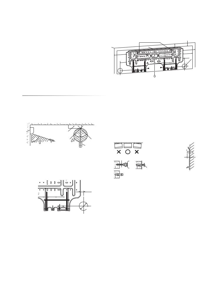
Mounting the installation plate
Anchor bolt holes
50
Hook
To unit out line 240mm
170 |
|
|
|
240mm |
|
|
|
|
|
|
|
is |
|
To unit out line |
|
|
|
|
|
|
|
side edge |
hole |
To unit out line |
|
|
|
|
|
|
|
leftthe |
pipeof |
35mm |
|
|
|
|
|
|
|
85mmfrom |
thecenter |
120mm |
|
|
|
180 |
240 |
|
85 |
|
|
To unit out line |
|
|
|
|
|
|
Offset |
|
0 |
23 |
35 |
120 |
|
|
Hook
Hook
Pipe hole 7 Mounting Thread
screw
Weight
Indoor unit
|
04 |
|
|
isedgesiderightthefrom23mm Offset holepipeofcenterthe |
170 |
frommorefloor |
|
132 |
|||
|
23 |
|
|
|
65 |
mm |
2 m or |
|
|
||
|
|
|
|
Pipe hole ( 65 mm)
1 Installation plate
Remote control
•A place where there are no obstacles such as a curtain that may block the signal from the remote control.
•Do not install the remote control in a place exposed to direct sunlight or close to a heating source such as a stove.
•Keep the remote control at least 1 m apart from the nearest TV set or stereo equipment. (This is necessary to prevent image disturbances or noise interference.)
•The location of the remote control should be determined as shown below.
(Side view) |
(Top view) |
|
|
|
unit |
|
Indoor unit |
|
|
Indoor |
|
|
|
|
|
4 |
5 |
45 |
|
5 |
|
Reception |
|
|
7 |
|
|
|
|
Reception |
Remote |
range |
|
Remote control |
control |
|
|
||
range |
|
|
|
|
|
|
|
|
|
Cutting a Hole and Mounting
Installation Plate
Cutting a hole
When installing the refrigerant pipes from the rear
center e |
from m |
|
hole pipe of |
side right the |
23 mm |
|
is edge |
|
|
|
35 |
120 |
180 |
240 |
Pipe hole
 65 mm
65 mm
The center of the pipe hole is above the arrow.
1.After determining the pipe hole position on the mounting plate (A), drill the pipe hole ( 65 mm) at a slight downward slant to the outdoor side.
When the installation plate is directly mounted
on the wall
1.Securely fit the installation plate onto the wall by screwing it in the upper and lower parts to hook up the indoor unit.
2.To mount the installation plate on a concrete wall with anchor bolts, use the anchor bolt holes as illustrated in the below figure.
3.Install the installation plate horizontally in the wall.
CAUTION
When installing the installation plate with a mounting screw, do not use the anchor bolt holes. Otherwise, the unit may fall down and result in personal injury and property damage.
Installation plate
(Keep horizontal direction.)
Anchor bolt 
Projection
15 mm or less
5 mm dia. hole
7 Mounting screw4 x 25 s
 Clip anchor (local parts)
CAUTION
Failure to firmly install the unit may result in personal injury and property damage if the unit falls.
•In case of block, brick, concrete or similar type walls, make 5 mm dia. holes in the wall.
•Insert clip anchors for appropriate mounting screws 7.
NOTE
•Secure four corners and lower parts of the installation plate with 4 to 6 mounting screws to install it.
NOTE
•When drilling a wall that contains a metal lath, wire lath or metal plate, be sure to use a pipe hole brim ring sold separately.
3
Toshiba 1110651129 (01_EN).indd 4 |
2/5/09 5:29:28 PM |
 Loading...