


outdoor@unit@installation@manual
instructions@pour@l¹installation@de@l¹unite@d¹exterieur
installationshandbuch@aussengerët
manuale@di@installazione@dell¹unita¹@esterna
manual@de@instalaciún@de@la@unidad@exterior
AIR CONDITIONER (MULTI-SPLIT TYPE)
CLIMATISEUR (TYPE “MULTI-FENTES”) KLIMAGERÄT (MULTI-SPLIT TYP)
CONDIZIONATORE D’ARIA (TIPO MULTIAMBIENTE)
ACONDICIONADOR DE AIRE (TIPO MULTI-SPLIT) For general public use
Pour utilisation grand public Für allgemeine Verwendung Per l’uso in generale
Para el uso público general
Heat pump |
/ |
Cooling only |
Pompe à chaleur |
/ |
Refroidissement uniquement |
Wärmepumpe |
/ |
Nur Kühlung |
Pompa di calore |
/ |
Solo raffreddamento |
Bomba de calor |
/ |
Sólo refrigeración |
RAS-3M26YAV-E
RAS-4M27YAV-E / RAS-4M27YACV-E
Thank you very much for purchasing TOSHIBA
Air Conditioner. Please read this Installation manual carefully before using your Air Conditioner.
Avant tout, merci d’avoir porté votre choix sur un climatiseur TOSHIBA. Avant de le mettre en service, prière de lire attentivement ce Manuel d’installation.
Wir danken lhnen für den Kauf dieses TOSHIBA-Klimageräts. Lesen Sie bitte diese. Installations-Handbuch aufmerksam durch, bevor Sie das Gerät in Betrieb nehmen.
Vi ringraziamo per l’acquisto del condizionatore d’aria TOSHIBA.
Si prega di leggere questo Manuale di installazione prima di usare l’apparecchio.
Muchas gracias por la adquisición de un acondicionador de aire TOSHIBA. Por favor lea detenidamente este Manual de instalación, antes de usar su acondicionador de aire.

CONTENTS / SOMMAIRE / INHALT / INDICE / CONTENIDOS
Precautions for safety ............................................. |
4 |
Accessory and Installation Parts ........................... |
5 |
Refrigerant Piping ................................................... |
6 |
Installation Place ..................................................... |
6 |
Optional Installation Parts (Local Supply) ............. |
6 |
Optional Installation Parts (Separate Sold) ........... |
6 |
Refrigerant Piping Connection ............................... |
6 |
Installation ............................................................... |
7 |
Evacuating ............................................................... |
8 |
Electrical Work ......................................................... |
9 |
Check and Test Operation ..................................... |
10 |
MISWIRING (MISPIPING) CHECK ......................... |
10 |
Useful Functions ................................................... |
11 |
Installation/Servicing Tools ................................... |
11 |
MESURES DE SECURITE ...................................... |
12 |
Accessoires et pièces d’installation .................... |
13 |
Tuyauterie pour réfrigérant ................................... |
14 |
Lieu d’installation .................................................. |
14 |
Pièce d’installation en option (Fourniture locale) . 14 |
|
Pièce d’installation en option |
|
(Vendues séparément) .......................................... |
14 |
Raccord de tuyauterie pour réfrigérant ............... |
14 |
Installation ............................................................. |
15 |
Evacuation ............................................................. |
16 |
Interventions électriques ...................................... |
17 |
Contrôles et essais ................................................ |
18 |
CONTROLES DES MAUVAISES CONNEXIONS |
|
(MAUVAIS RACCORDEMENTS) ............................ |
18 |
Fonctions supplementaires .................................. |
19 |
Outil d’installation /d’entretien ............................. |
19 |
SICHERHEITSVORKEHRUNGEN .......................... |
20 |
Zubehör und Installationsteile .............................. |
21 |
Kühlmittel-Leitungssystem .................................. |
22 |
Installations-Ort ..................................................... |
22 |
Optionale Installationsteile (örtlich lieferbar) ...... |
22 |
Optionale Installationsteile |
|
(getrennt erhältlich) ............................................... |
22 |
Kühlmittel-Rohrleitungs-Anschluß ...................... |
22 |
Installation ............................................................. |
23 |
Leerpumpen der Rohrleitungen ........................... |
24 |
Arbeiten an der Elektrik ........................................ |
25 |
Prüfund Testvorgang ........................................... |
26 |
ÜBERPRÜFEN AUF FALSCHE VERKABELUNG |
|
ODER ROHRVERLEGUNG .................................... |
26 |
Nützliche Funktionen ............................................ |
27 |
Installation/Wartungswerkzeuge .......................... |
27 |
PRECAUZIONI PER LA SICUREZZA ..................... |
28 |
Componenti accessori e per l’installazione ........ |
29 |
Tubazioni del refrigerante ..................................... |
30 |
Punto di installazione ............................................ |
30 |
Componenti opzionali per l’installazione |
|
(Fornitura locale) ................................................... |
30 |
Componenti opzionali per l’installazione |
|
(Vendute separatamente) ...................................... |
30 |
Collegamento delle tubazioni del refrigerante ... |
30 |
Installazione ........................................................... |
31 |
Svuotamento delle tubature ................................. |
32 |
Collegamenti elettrici ............................................ |
33 |
Operazioni di verifica e di prova ........................... |
34 |
VERIFICA DEGLI EVENTUALI ERRORI NEI |
|
COLLEGAMENTI ELETTRICI |
|
(NELLE TUBATURE) ............................................... |
34 |
FunzioniI utili ......................................................... |
35 |
Attrezzi per l’installazione/l’assistenza tecnica .. |
35 |
PRECAUCIONES SOBRE SEGURIDAD ................ |
36 |
Accesorios y componentes para la instalación .. |
37 |
Tubería de refrigerante .......................................... |
38 |
Sitio de instalación ................................................ |
38 |
Componentes opcionales de instalación |
|
(Provisión local) ..................................................... |
38 |
Componentes opcionales de instalación |
|
(De venta independiente) ...................................... |
38 |
Conexión de la tubería de refrigerante ................ |
38 |
Instalación .............................................................. |
39 |
Evacuación ............................................................. |
40 |
Trabajos eléctricos ................................................ |
41 |
Operación de control y prueba ............................. |
42 |
CONTROL DE CABLEADO INCORRECTO |
|
(TUBERÍA INCORRECTA) ...................................... |
42 |
Funciones útiles .................................................... |
43 |
Herramientas para la instalación/ |
|
el mantenimiento ................................................... |
43 |
ENGLISH
FRENCH
GERMAN
ITALIAN
SPANISH |
3

PRECAUTIONS FOR SAFETY
For general public use
Power supply cord of parts of appliance for outdoor use shall be more than polychloroprene sheathed flexible cord (Design H07 RN-F), or cord designation 245 IEC 66. (2.5 mm² or more)
UK PLUGS AND SOCKETS ETC (SAFETY) REGULATIONS 1994, SI NUMBER 1768
With regard to Schedule 3, item 7 of the above UK Regulations, this appliance must be permanently connected to the fixed wiring of the main electrical supply by means other than the use of an approved 13 Amp plug-top as outlined in the Regulations.
Electrical work must be carried by suitably qualified persons and in accordance with all relevant safety standards and codes of practice.
We recommend that the power supply for this appliance is derived from a suitably protected dedicated circuit. (for U.K. only)
CAUTION |
New Refrigerant Air Conditioner Installation |
•THIS AIR CONDITIONER ADOPTS THE NEW HFC REFRIGERANT (R410A) WHICH DOES NOT DESTROY OZONE LAYER.
R410A refrigerant is apt to be affected by impurity such as water, oxidizing membrane, and oils because pressure of R410A refrigerant is approx. 1.6 times of refrigerant R22. Accompanied with adoption of the new refrigerant, refrigerating machine oil has been also changed. Therefore, during installation work, be sure that water, dust, former refrigerant, or refrigerating machine oil does not enter into the refrigerating cycle of new-refrigerant air conditioner.
To prevent mixing of refrigerant or refrigerating machine oil, the sizes of connecting sections of charging port of the main unit or installation tools are different from those for the conventional refrigerant. Accordingly, the exclusive tools are required for the new refrigerant (R410A) as shown below.
For connecting pipes, use new and clean piping materials with high pressure-tight force, which were made for R410A only, so that water or dust does not enter. Moreover, do not use the existing piping because there are problems about pressure-tight force and inner impurity in the existing piping.
CAUTION |
To Disconnect the Appliance from the Mains Supply. |
This appliance must be connected to the mains by means of a switch with a contact separation of at least 3 mm.
The installation fuse (25A D type  ) must be used for the power supply line of this air conditioner.
DANGER |
Engage Dealer or Specialist for Installation. |
•FOR ELECTRICAL WORKS THE WIRING AND CABLES MUST BE PERFORMED IN COMPLIANCE WITH NATIONAL WIRING STANDARD OR REGULATION.
IF INCORRECT AND INCOMPLETE WIRING IS CARRIED OUT, IT WILL CAUSE AN ELECTRICAL FIRE OR ELECTRICAL SHOCK.
•USE THE SPECIFIED CABLE (1.0 mm2 or more) AND CONNECT TIGHTLY FOR INDOOR/OUTDOOR CONNECTION. CONNECT TIGHTLY AND CLAMP THE CABLE SO THAT EXTERNAL FORCE WILL NOT BE ACTED ON THE TERMINAL.
•WIRE ROUTING MUST BE PROPERLY ARRANGED SO THAT CONTROL BOARD COVER IS FIXED PROPERLY.
•DO NOT DAMAGE OR SCRATCH THE CONDUCTIVE CORE AND INNER INSULATOR OF THE CABLES.
•DO NOT DEFORM OR SMASH ON THE SURFACE OF THE CABLES. DO NOT PRESS OR FIX THE CORD AND CABLES FIRMLY WITH STAPLES, etc.
•DO NOT USE THE INTER-CONNECTING CABLE. NEVER EXECUTE THE CONNECTION OF WIRING WITH OTHER METHOD THAN THE APPROVED ONE. OTHERWISE, OVERHEAT, SMOKE OR FIRE MAY BE GENERATED BY CONTACT ERROR.
•TURN OFF MAIN POWER SUPPLY AND BREAKER BEFORE ATTEMPTING ANY ELECTRICAL WORK. MAKE SURE ALL POWER SWITCHES AND BREAKER TURN OFF. FAILURE TO DO SO MAY CAUSE ELECTRIC SHOCK.
•CONNECT THE CONNECTING CABLE CORRECTLY. IF THE CONNECTING CABLE IS CONNECTED BY WRONG WAY, ELECTRIC PARTS MAY BE DAMAGED.
4

• GROUNDING WIRE WORKS MUST BE CONSTRUCTED IN COMPLIANCE WITH INSTALLATION MANUAL. |
|
|
• BE SURE TO USE THE CORD-CLAMPS AND THE UNIT COVER TO THE SPECIFIED POSITIONS WITH |
|
|
|
||
ATTACHED TO THE PRODUCT. MOUNT THE UNIT COVER FOR CABLES OF CONNECTING SECTION |
|
|
FIRMLY WITH THE SCREWS. |
|
|
• DO NOT INSTALL NEAR CONCENTRATIONS OF COMBUSTIBLE GAS OF GAS VAPORS. |
ENGLISH |
|
FAILURE TO FOLLOW THIS INSTRUCTION CAN RESULT IN FIRE OR EXPLOSION. |
||
|
||
• IF A REFRIGERATION GAS LEAKS DURING INSTALLATION, BE SURE TO PERFORM VENTILATION. |
|
|
IF THE REFRIGERANT GAS COMES INTO CONTACT WITH FIRE, A POISONOUS GAS MAY OCCUR. |
|
|
WHEN INSTALLING AN AIR CONDITIONER, DO NOT ALLOW AIR OR MOISTURE TO REMAIN IN THE |
|
|
REFRIGERATION CYCLE. OTHERWISE, PRESSURE IN THE REFRIGERATION CYCLE MAY BECOME |
|
|
ABNORMALLY HIGH SO THAT A RUPTURE OR PERSONAL INJURY MAY BE CAUSED. |
|
WARNING
•Never modify this unit by removing any of the safety guards of by-passing any of the safety interlock switches.
•Do not install in a place which cannot bear the weight of the unit. Personal injury and property damage can result if the unit falls.
•Before doing the electrical work, attach an approved cable to the power supply cord. And make sure the equipment to be earthed.
•For installation, use the tools and piping materials exclusively manufactured for R410A, and install securely in compliance with this Installation Manual.
Pressure of the used HFC R410A refrigerant becomes higher approx. 1.6 times of that of the conventional refrigerant. Therefore, if the exclusive piping materials are not used or incomplete installation is carried out, it may cause a rupture or personal injury, as well water leak, electrical shock, and a fire may be caused.
•When installing or moving the air conditioner, do not mix air and so on than the specified refrigerant (R410A) in the refrigeration cycle. If air and so on is mixed, the pressure in the refrigeration cycle may become abnormally high so that personal injury may be caused by a rupture.
CAUTION
•Exposure of unit or water or other moisture before installation will result in an electrical short. Do not store in a wet basement or expose to rain or water.
•After unpacking the unit, examine it carefully for possible damage.
•Do not install in a place that can increase the vibration of the unit. Do not install in a place that can amplify the noise level of the unit or where noise and discharged air might disturb user’s neighbors.
•To avoid personal injury, be careful when handling parts with sharp edges.
•Please read the installation manual carefully before installing the unit. It contains further important instructions for proper installation.
•Never install a power capacitor for power factor improvement.
Required tools for installation work
1)Philips screw driver
2)Hole core drill (65 mm)
3)Spanner
4)Pipe cutter
5)Knife
6)Reamer
7)Gas leak detector
8)Tape measure
9)Thermometer
10)Mega-tester
11)Electro circuit tester
12)Hexagonal wrench
13)Flare tool
14)Pipe bender
15)Level vial
16)Metal saw
R410A (Special requirement)
17)Gauge manifold
(Charge hose : R410A special requirement)
18)Vacuum pump
(Charge hose : R410A special requirement)
19)Torque wrench
1/4 (17 mm) 16N•m (1.6 kgf•m) 3/8 (22 mm) 42N•m (4.2 kgf•m) 1/2 (26 mm) 55N•m (5.5 kgf•m)
20)Copper pipe gauge adjusting projection margin
21)Vacuum pump adapter
Accessory and Installation Parts
|
|
SPECIFICATIONS |
1 |
2 |
3 |
|
Outdoor unit |
|
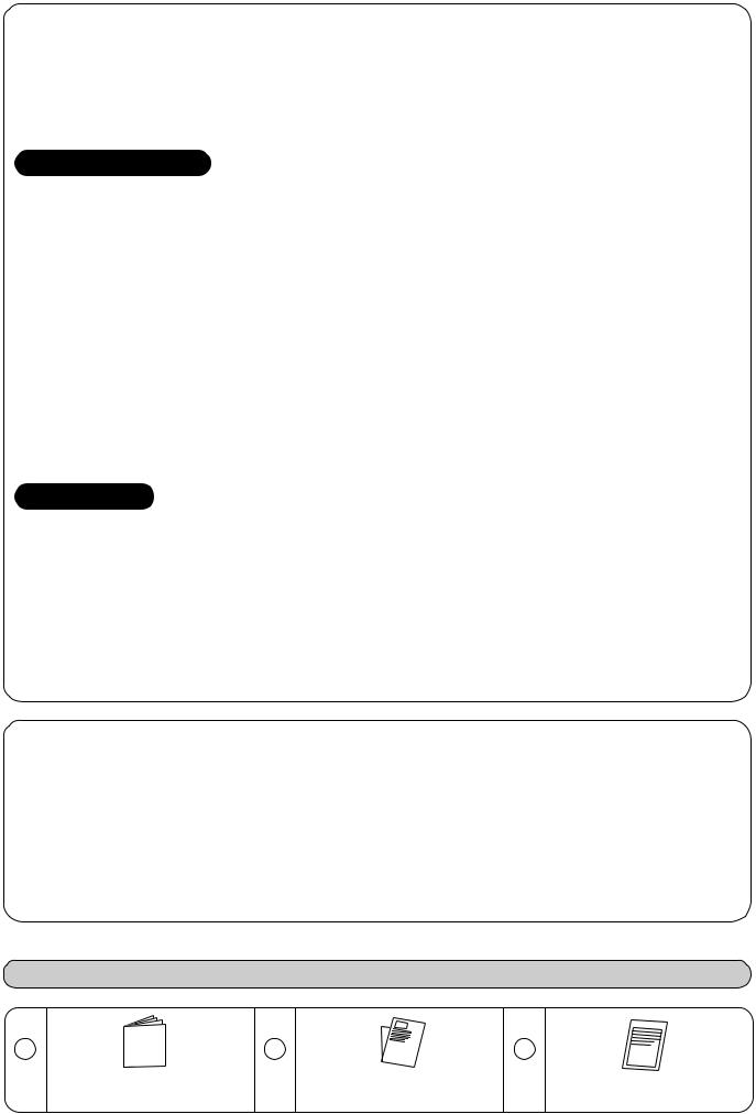
Owner's manual x 1 |
installation manual x 1 |
Specifications x 1 |
5
Refrigerant Piping
•Piping kit used for the conventional refrigerant cannot be used.
•Use copper pipe with 0.8 mm or more thickness.
•Flare nut and flare works are also different from those of the conventional refrigerant.Take out the flare nut attached to the main unit of the air conditioner, and use it.
Optional Installation Parts
(Separate Sold)
Parts name
RB-M43RE Reducer (Ø12.7 → Ø9.52)
RB-M34EE Expander (Ø9.52 → Ø12.7)
Installation Place
•A place which provides the spaces around the outdoor unit.
•A place where the operation noise and discharged air do not disturb your neighbors.
•A place which is not exposed to a strong wind.
•A place which does not block a passage.
•When the outdoor unit is to be installed in an elevated position, be sure to secure its feet.
•There must be sufficient spaces for carrying the unit into and out of the site.
•A place where the drain water does not raise any problem.
Refrigerant Piping Connection
CAUTION
KEEP IMPORTANT 4 POINTS FOR PIPING WORK
1.Take away dust and moisture. (Inside of the connecting pipes)
2.Tight connection (between pipes and unit)
3.Evacuate the air in the connecting pipes using VACUUM PUMP.
4.Check gas leak. (connected points)
Flaring
1. Cut the pipe with a pipe cutter.
CAUTION
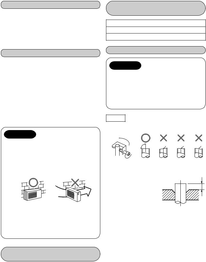
1.Install the outdoor unit without anything blocking the air discharging.
2.When the outdoor unit is installed in a place exposed always to a strong wind like a coast or on a high story of a building, secure the normal fan operation using a duct or a wind shield.
3.Specially in windy area, install the unit to prevent the admission of wind.
Strong
wind
4.Installation in the following places may result in trouble. Do not install the unit in such places.
•A place full of machine oil.
•A place full of sulfide gas.
•A place where high-frequency waves are likely to be generated as from audio equipment, welders, and medical equipment.
Optional Installation Parts
(Local Supply)
|
Parts name |
Q’ty |
|
|
|
|
|
|
Refrigerant piping |
Each |
|
A |
Liquid side : Ø6.35 mm |
||
one |
|||
|
Gas side : Ø9.52 mm or Ø12.7 mm |
||
|
|
||
|
|
|
|
B |
Pipe insulating material |
1 |
|
(polyethylene foam, 6 mm thick) |
|||
|
|
||
C |
Putty, PVC tapes |
Each |
|
one |
|||
|
|
90˚ |
Obliquity Roughness |
Warp |
2. Insert a flare nut into the pipe, and flare the pipe.
As the flaring sizes of R410A differ from those of |
|
refrigerant R22, the flare tools newly manufactured |
|
for R410A are recommended. |
B |
However, the conventional |
|
tools can be used by |
|
adjusting projection |
|
margin of the copper |
|
pipe. |
|
• Projection margin in flaring : B (Unit : mm)
Rigid (Clutch type)
Outer dia. |
R410A tool used |
Conventional tool used |
|||
of copper |
|
|
|
|
|
R410A |
R22 |
R410A |
R22 |
||
pipe |
|||||
|
|
|
|
|
|
6.35 |
0 to 0.5 |
(Same as left) |
1.0 to 1.5 |
0.5 to 1.0 |
|
|
|
|
|
|
|
9.52 |
0 to 0.5 |
(Same as left) |
1.0 to 1.5 |
0.5 to 1.0 |
|
|
|
|
|
|
|
12.7 |
0 to 0.5 |
(Same as left) |
1.0 to 1.5 |
0.5 to 1.0 |
|
|
|
|
|
|
|
Imperial (Wing nut type)
Outer dia. of copper pipe |
R410A |
R22 |
|
|
|
6.35 |
1.5 to 2.0 |
1.0 to 1.5 |
|
|
|
9.52 |
1.5 to 2.0 |
1.0 to 1.5 |
|
|
|
12.7 |
2.0 to 2.5 |
1.5 to 2.0 |
|
|
|
6

• Flaring size : A (Unit : mm)
Outer dia. of |
|
A -+00.4 |
|
|
|
|
|
copper pipe |
R410A |
|
R22 |
|
|
||
|
|
|
|
6.35 |
9.1 |
|
9.0 |
|
|
|
|
9.52 |
13.2 |
|
13.0 |
|
|
|
|
12.7 |
16.6 |
|
16.2 |
|
|
|
|
* In the case of flaring for R410A with the |
|
|
A |
|
|
conventional flare tool, pull out it approx. |
|
|
|
|
|
0.5 mm more than that for R22 to adjust |
|
|
|
||
|
|
|
|||
|
|
|
|||
to the specified flare size. The copper |
|
|
|
||
pipe gauge is useful for adjusting projec- |
|
|
|
||
tion margin size. |
|
|
|
||
Installation
NOTE : For installation, at least 3 dimensions should be kept free from obstacles (walls).
|
|
|
or more |
|
|
|
|
wall more |
600mm |
100mm |
|
|
|
100mm |
or |
|
|
or |
||
from |
|
|
|
|||
|
|
|
from |
wall |
||
|
|
|
|
|||
|
|
|
|
more |
|
|
1.Piping connections to the outdoor unit should be arranged in the sequence A, B, C, D starting from the bottom. (For each piping connection, the gas pipe is on the bottom and the liquid pipe is on the top.)
2.When multiple indoor units are to be connected to the outdoor unit, make the ends of the pipes and wires from each indoor unit to ensure that they will be connected to the outdoor unit correctly. (Problems caused by indoor units being connected to the outdoor unit incorrectly are very common in multiple-unit installations.)
3.The length and height difference of the connecting pipes between the indoor and outdoor units must be within the ranges indicated below.
• |
Total piping length : |
|
|
4 units (A + B + C + D) Multi, |
|
|
Non. Additional refrigerant .................. |
70 m |
|
3 units (A + B + C) Multi, |
|
|
Non. Additional refrigerant .................. |
50 m |
• |
Minimum piping length : |
|
|
A or B or C or D = 2 m or more |
|
•Maximum indoor piping length : A or B or C or D = 25 m or less
•Maximum piping height difference :
A or B or C or D = 15 m or less |
|
|
|
|
|
A |
|
|
C |
|
• Maximum piping/height |
|
|
|
|
|
|
|
|||
|
|
|
|
|
|
|
|
|
|
|
|
|
|
|
|
|
|
|
|
|
|
difference between 2 units |
less |
|
|
|
Outdoor |
|
|
|
||
= 15 m or less |
|
|
|
|
|
|
||||
|
or |
|
|
|
unit |
|
D |
|||
|
15 m |
|
|
|
|
|
|
|
|
|
|
|
|
|
|
|
|||||
|
|
|
|
|
|
|||||
|
|
|
|
|
|
|||||
|
|
|
|
|
|
|
|
|
|
|
|
600mm |
or |
more |
|
from wall |
||
or |
more |
|
|
600mm
As shown in the figure, hang power cord and connecting cable downward, and take out it along piping connection port.
Fixing bolt arrangement of outdoor unit
600
Suction side
365
Diffuser
•Secure the outdoor unit with the fixing bolts and nuts if the unit is likely to be exposed to a strong wind.
•Use Ø8 mm or Ø10 mm anchor bolts and nuts.
4.Connect 2 or more indoor units for heat pump.
5.If the outdoor unit is to be mounted on a wall, make sure that the platform supporting it is sufficiently strong. The platform should be designed and manufactured to maintain its strength over a long period of time, and sufficient consideration should be given to ensuring that the outdoor unit will not fall.
6.When the outdoor unit is to be mounted high on a wall, take particular care to ensure that parts do not fall installer is protected.
7.When doing installation work on level ground, it is usual to wiring and piping connections to the indoor units. And/then make to the outdoor unit.
However if outdoor work is difficult it is possible instead to make changes to the procedure.
For example by making adjustments to the wiring and piping length on the inside (rather than the outside).
How to remove the side panel
1. Remove screws of the side panel.
2. Pull the side panel downward.
Side panel
7
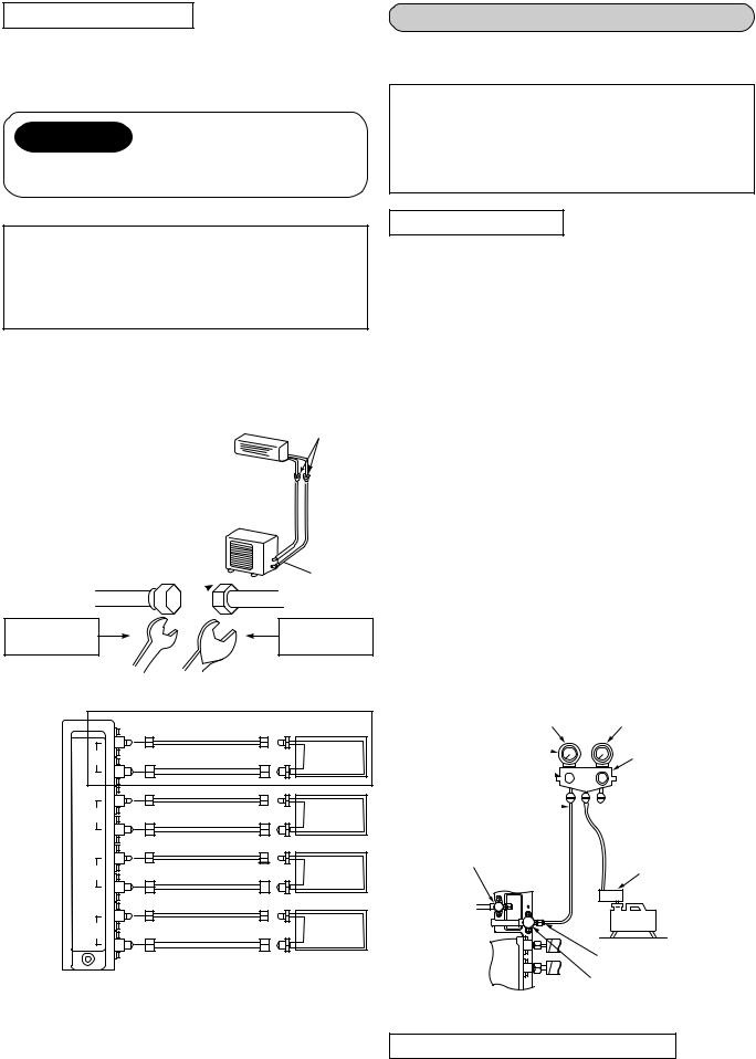
Tightening connection
Align the centers of the connecting pipes and tighten the flare nut as far as possible with your fingers. Then tighten the nut with a spanner and torque wrench as shown in the figure.
CAUTION
•Do not apply excess torque. Otherwise, the nut may crack depending on the conditions.
|
(Unit : N·m) |
Outer dia. of copper pipe |
Tightening torque |
|
|
Ø6.35 mm |
14 to 18 (1.4 to 1.8 kgf•m) |
|
|
Ø9.52 mm |
33 to 42 (3.3 to 4.2 kgf•m) |
|
|
Ø12.7 mm |
50 to 62 (5.0 to 6.2 kgf•m) |
|
|
• Tightening torque of flare pipe connections
Pressure of R410A becomes higher than that of R22. (Approx. 1.6 times) Therefore, using a torque wrench, tighten firmly the flare pipe connecting sections which connect the indoor and outdoor
units up to the specified tightening torque.
Incorrect connections may cause not only a gas leakage,
but also a trouble of the refrigeration cycle.

 Flare at
  outdoor unit side
Half union 
 Flare nut
Externally |
Internally |
threaded side |
threaded side |
Use a wrench to secure. |
Use a torque wrench to tighten. |
|
4M27 only |
|
|
Ø6.35 |
|
D |
Ø9.52 |
D UNIT |
|
|
|
|
Ø6.35 |
|
C |
Ø9.52 |
C UNIT |
Outdoor |
|
|
|
|
|
unit |
Ø6.35 |
|
B |
Ø9.52 |
B UNIT |
|
|
|
|
Ø6.35 |
|
A |
Ø12.7 |
A UNIT |
|
|
Indoor unit
|
|
|
Connectable capacity class |
|
|
|
|
|||
|
A |
|
B |
|
C |
|
D |
|
|
Total |
|
10, |
13 |
16 |
|
16 |
|
—— |
|
|
|
3M26 |
(with reducer) |
(with expander) |
(with expander) |
|
|
45 |
||||
|
|
|
||||||||
|
16 |
|
10, |
13 |
10, |
13 |
—— |
|
|
|
|
10, |
13 |
16 |
|
16 |
|
16 |
|
|
|
4M27 |
(with reducer) |
(with expander) |
(with expander) |
(with expander) |
52 |
|||||
|
16 |
|
10, |
13 |
10, |
13 |
10, |
13 |
|
|
|
|
|
|
|
|
|
|
|
|
|
Evacuating
After the piping has been connected to all indoor unit(s), you can perform the air purge together at once.
AIR PURGE
Evacuate the air in the connecting pipes and in the indoor unit using vacuum pump.
Do not use the refrigerant in the outdoor unit. For details, see the manual of vacuum pump.
Use a vacuum pump
Be sure to use a vacuum pump with counter-flow prevention function so that inside oil of the pump does not flow backward into pipes of the air conditioner when the pump stops. (If inside oil of the vacuum pump enters into the air conditioner which adopts R410A, a trouble of the refrigeration cycle may be caused.)
1.Connect the charge hose from the manifold valve to the service port of the gas side packed valve.
2.Connect the charge hose to the port of vacuum pump.
3.Open fully the low pressure side handle of the gauge manifold valve.
4.Operate the vacuum pump to start for evacuating.
Perform evacuating for about 35 minutes if the piping length is total 70 meters.
(25 minutes for total 50 meters)
(assuming a pump capacity of 27 liters per minute.) Then confirm that the compound pressure gauge reading is –101 kPa ( –76 cmHg).
5.Close the low pressure side valve handle of gauge manifold.
6.Open fully the valve stem of the packed valves (both sides of Gas and Liquid).
7.Remove the charging hose from the service port.
8.Securely tighten the caps on the packed valves.
Compound pressure gauge Pressure gauge
–101kPa (–76cmHg) 
Handle Lo 

Charge hose  (For R410A only)
Packed valve at liquid side
Manifold valve
 Handle Hi
(Keep full closed)
 Charge hose (For R410A only)
Vacuum pump adapter
for counter-flow prevention (For R410A only)
Vacuum
pump
Service port
(Valve core (Setting pin)) Packed valve at gas side
Packed valve handling precautions
•Open the valve stem all the way out ; do not try to open it beyond the stopper.
•Securely tighten the valve stem cap in torque as follows:
8

Gas side (Ø12.7 mm) |
50 to 62 N•m (5.0 to 6.2 kgf•m) |
3 units (A + B + C) Multi |
|
||
Gas side (Ø9.52 mm) |
33 to 42 N•m (3.3 to 4.2 kgf•m) |
Terminal block (Connecting cable) |
|
||
Liquid side (Ø6.35 mm) 14 to 18 N•m (1.4 to 1.8 kgf•m) |
|
|
Service port |
14 to 18 N•m (1.4 to 1.8 kgf•m) |
|
Hexagonal wrench is required.
Screw
Connecting cable (B unit)
Connecting cable |
Connecting cable |
Power cord |
(A unit) |
(C unit) |
|
Electrical Work
For the air conditioner that has no power cord, connect a power cord to it as mentioned below.
Model |
3 Units Multi |
|
4 Units Multi |
|||
|
|
|
|
|
||
3M26YAV-E |
|
4M27YAV-E |
|
4M27YACV-E |
||
|
|
|
||||
|
|
|
|
|
|
|
Power |
|
|
220 – 240 V |
|
||
supply |
Single phase 50/60 Hz |
|||||
|
|
|
|
|
|
|
Maximum |
|
|
|
|
|
|
running |
15.3 |
|
15.3 |
|
14.8 |
|
current |
|
|
|
|
|
|
|
|
|
|
|
|
|
Installation |
25 A (D type |
) |
||||
fuse rating |
||||||
|
|
|
|
|
||
|
|
|
|
|||
Power |
H07 RN-F or 245 IEC 66 |
|||||
cord |
|
(2.5 mm2 or more) |
|
|||
How to wire
1.Connect the connecting cable to the terminal as identified with their respective matched numbers on the terminal block of indoor and outdoor unit.
H07 RN-F or 245 IEC 66 (1.0 mm2 or more)
2.When connecting the connecting cable to the outdoor unit terminal, prevent water coming in the outdoor unit.
3.Insulate the unused cords (conductors) stripped the sheath of connecting cable with PVC tape.
Process them so that they do not touch any electrical or metal parts.
4.For inter-unit wiring, do not use a cut wire jointed to another on the way.
Use wires long enough to cover the entire length.
4 units (A + B + C + D) Multi
Terminal block (Connecting cable)
Screw |
|
|
|
Connecting cable |
Connecting cable |
||
Connecting cable |
(B unit) |
|
(D unit) |
Connecting cable |
Power cord |
||
(A unit) |
|
(C unit) |
|
CAUTION
•Wrong wiring connection may cause some electrical parts burn out.
•Be sure to use the cord clamps specified positions with attached to the product.
•Do not damage or scratch the conductive core and inner insulator of power and inter-connecting cables when peeling them.
•Be sure to comply with local cords on running the wire from outdoor unit to indoor unit (size of wire and wiring method etc.)
•Use the power cord and Inter-connecting cable with specified thickness, specified type, and protective devices specified.
Stripping length power cord and connecting cable
L |
N |
10 |
10 |
|
|
30 |
|
40 |
|
|
|
|
|
Earth line |
|
|
Power cord |
1 |
2 |
3 |
|
|
|
10 |
|
|
|
10
40
30
Earth line
 Connecting cable
CAUTION
•The installation fuse (25A D type  ) must be used for the power supply line of this air conditioner.
•If incorrect/incomplete wiring is carried out, it will cause an electrical fire or smoke.
•Prepare the power supply for exclusive use with the air conditioner.
•This product can be connected to the mains.
Connection to fixed wiring :
A switch which disconnects all poles and has a contact separation of at least 3 mm must be incorporated in the fixed wiring.
9

Check and Test Operation
For R410A, use the leak detector exclusively manufactured for HFC refrigerant (R410A, R134a, etc.).
*The conventional leak detector for HCFC refrigerant (R22, etc.) cannot be used because its sensitivity for HFC refrigerant lowers to approx. 1/40.
•Pressure of R410A becomes approx. 1.6 times of that of R22. If installation work is incompletely finished, a gas leakage may
occur in the cases such as pressure rise during operation. Therefore, be sure to test the piping connections for leaking.
• Check the flare nut connections, valve stem cap connections and service port cap connections for gas leak with a leak detector or soap water.
Flare nut connections (Indoor unit)
Flare nut
 connections (Outdoor unit)
MISWIRING (MISPIPING) CHECK
Make sure that the wiring and piping for each room have the same alphabetical codes (A, B, C, D). Connect and secure the power cord.
Use the power cord/cables with thickness, type and protective devices specified in this manual. Insulate the unused cords (conductors) with PVC tape.
1.Turn on the power breaker.
2.Open side panel of the outdoor unit.
3.Set the indoor unit to COOL mode.
•It is unnecessary to set the temperature.
•Miswiring check can not be executed when outdoor air temperature is 5°C or less.
4.Start the check
•Disconnect the miswiring check connector (color : Red) from P.C. board of inverter.
5.During check (Check time 3 to 20 minutes).
•When an error described in the table below occurred check operation stops and error code is displayed on LED.
6.After check, the result of check is displayed on LED.
•The Comp. stop when miswiring (mispiping) error occurred.
•Confirm the contents of table below.
•Turn off the power breaker.
•Correct miswiring/mispiping.
•Connect the miswiring check connector.
•Execute the check operation again.
•Automatically return to the normal operation when it is normal.
7.Return to normal operation.
•To return to the normal operation during check operation or after miswiring (mispiping) error has been determined, connect the miswiring check connector.
Miswiring (mispiping) check by LED Indication
• For this outdoor unit, the self-miswiring (mispiping) check is possible by using five LEDs (1 Yellow + 4 Red). *LEDs (D800 to D804) are provided on P.C. board of the inverter.
LED |
|
D800 D801 D802 D803 D804 |
Description |
|
|
|||
|
|
l l |
l |
l |
l |
Normal operation (no error) |
|
LED |
|
|
|
|
|
|
Checking A unit |
|
|
|
|
|
l |
l |
l |
D800 D801 D802 D803 D804 |
||
During |
|
l |
|
l |
l |
Checking B unit |
|
|
check |
|
l |
l |
|
l |
Checking C unit |
|
|
|
*1 |
l |
l |
l |
|
Checking D unit |
|
|
|
|
¤ |
l |
l |
l |
Crush/Clog of Pipe A |
|
|
|
|
l |
¤ |
l |
l |
Crush/Clog of Pipe B |
|
|
|
*1 |
l |
l |
¤ |
l |
Crush/Clog of Pipe C |
|
|
|
l |
l |
l |
¤ |
Crush/Clog of Pipe D |
|
|
|
|
|
¤ |
¤ |
l |
l |
Miswiring/Mispiping or Crush/Clog of Pipe A, B |
Miswiring (mispiping) |
|
|
|
¤ |
l |
¤ |
l |
Miswiring/Mispiping or Crush/Clog of Pipe A, C |
||
|
|
check connector |
||||||
|
1 |
¤ |
l |
l |
¤ |
Miswiring/Mispiping or Crush/Clog of Pipe A, D |
(Color:Red) |
|
Result of * |
l |
¤ |
¤ |
l |
Miswiring/Mispiping or Crush/Clog of Pipe B, C |
Check mode |
Short → Open |
|
judgement |
1 |
l |
¤ |
l |
¤ |
Miswiring/Mispiping or Crush/Clog of Pipe B, D |
Normal operation |
Short |
|
||||||||
|
* |
|
|
¤ |
¤ |
Miswiring/Mispiping or Crush/Clog of Pipe C, D |
|
|
|
*1 |
l |
l |
|
|
|||
|
|
¤ |
¤ |
¤ |
l |
A, B, C Miswiring/Mispiping |
|
|
|
|
¤ |
¤ |
l |
¤ |
A, B, D Miswiring/Mispiping |
LED : Light Emitting Diode |
|
|
|
|
|
|||||
|
|
¤ |
l |
¤ |
¤ |
A, C, D Miswiring/Mispiping |
¤ : LED ON |
|
|
|
l |
¤ |
¤ |
¤ B, C, D Miswiring/Mispiping |
l : LED OFF |
|
|
|
|
¤ |
¤ |
¤ |
¤ |
A, B, C, D Miswiring/Mispiping |
: LED Flash |
|
|
|
Packed valve keeps closed |
*1 : 4 units Multi model only |
|||||
|
|
|
|
|
|
|
||
10

|
|
|
Useful Functions |
Self-Diagnosis by LED Indication |
||||||
• For this outdoor unit, the self-diagnosis is possible by using five LEDs (1 Yellow + 4 Red). |
||||||||||
*LEDs (D800 to D804) are provided on P.C. board of the inverter. |
1. |
If a trouble occurs, LED goes on |
||||||||
|
LED indication |
|
Indoor |
Contents |
||||||
|
D800 D801 D802 D803 D804 alarm code |
|
according to the contents of |
|||||||
|
|
|
|
|||||||
|
l |
l |
l |
l |
l |
None |
Normal running |
|
|
trouble as shown in the left table. |
|
|
2. |
When two or more troubles occur, |
|||||||
|
l |
¤ |
l |
l |
l |
14 |
IGBT short circuit, Compressor motor rare short |
|||
|
¤ |
¤ l |
l |
l |
16 |
Trouble on position detecting circuit |
|
LEDs go on cyclically (alternately). |
||
*2 |
l |
l |
¤ |
l |
l |
17 |
Trouble on current detecting circuit |
3. |
Usually, LEDs go off. |
|
¤ |
l |
¤ |
¤ |
l |
18 |
Outdoor heat exchanger temp. sensor (TE) fault |
|
|
||
2 |
l |
l |
¤ |
¤ |
l |
18 |
Suction temp. sensor (TS) fault |
|
|
|
* |
l |
¤ |
¤ l |
l |
19 |
Discharge temp. sensor (TD) fault |
|
LED |
||
|
¤ |
¤ |
¤ l |
l |
1A |
Trouble on outdoor fan motor |
|
|
D800 D801 D802 D803 D804 |
|
|
|
|
|
|||||||
|
l |
l |
l |
¤ |
l |
1B |
Outdoor temp. sensor (TO) fault |
|
|
|
|
¤ |
l |
¤ |
l |
l |
1C |
Trouble on compressor system |
|
|
|
|
¤ |
¤ |
¤ |
¤ l |
1C |
Temp. sensor (TGa) fault at A room gas side |
|
|
||
|
¤ |
l |
l |
l |
¤ |
1C |
Temp. sensor (TGb) fault at B room gas side |
|
|
|
|
¤ |
¤ |
l |
l |
¤ |
1C |
Temp. sensor (TGc) fault at C room gas side |
|
|
|
1 |
l |
l |
l |
l |
¤ |
1C |
Temp. sensor (TGd) fault at D room gas side |
|
|
|
* |
l |
¤ |
¤ l |
¤ |
1C |
Gas leakage, TS sensor out of place, PMV, sensor fault |
|
|
||
|
¤ |
¤ |
¤ l |
¤ |
1C |
TE sensor out of place, Indoor heat exchanger sensor |
|
|
||
|
(TC) out of place, PMV, sensor fault |
|
|
|||||||
|
|
|
|
|
|
|
|
|
||
|
l |
l |
l |
¤ |
¤ |
1C |
Miswiring at indoor or outdoor, Gas leakage, TS, |
IGBT : Insulated Gate Bipolar Transistor |
||
|
TC sensor out of place, PMV, sensor fault |
|||||||||
|
¤ |
¤ l |
¤ |
¤ |
1C |
Communication trouble between MCU |
PMV : Pulse Modulating Valve |
|||
|
¤ : LED ON |
|||||||||
|
¤ |
l |
l |
¤ |
l |
1D |
Compressor lock |
|
||
|
|
l |
: LED OFF |
|||||||
|
l |
¤ |
l |
¤ |
l |
1E |
Trouble on discharge temp, Gas leakage |
|||
|
1 : 4 units Multi model only |
|||||||||
|
¤ |
¤ l |
¤ |
l |
1F |
Compressor break down |
|
*2 |
: Heat pump model only |
|
|
|
|
|
|
|
|
|
|
* |
|
|
|
Installation/Servicing Tools |
Changes in the product and components |
|||||||
In the case of an air conditioner using R410A, in order to prevent any other refrigerant from being charged accidentally, to service port diameter of the outdoor unit control valve (3 way valve) has been changed. (1/2 UNF 20 threads per inch)
•In order to increase the pressure resisting strength of the refrigerant piping flare processing diameter and size of opposite side of flare nuts has been changed. (for copper pipes with nominal dimensions 1/2 and 5/8)
New tools for R410A
New tools for R410A |
Applicable to R22 model |
Changes |
|
|
X |
|
As pressure is high, it is impossible to measure by means of conven- |
Gauge manifold |
|
tional gauge. In order to prevent any other refrigerant from being |
|
|
|
|
charged, each port diameter is changed. |
|
|
|
|
|
X |
|
In order to increase pressure resisting strength, hose materials and |
Charge hose |
|
port size are changed (to 1/2 UNF 20 threads per inch). |
|
|
|
|
When purchasing a charge hose, be sure to confirm the port size. |
|
|
|
|
Electronic balance |
|
|
As pressure is high and gasification speed is fast, it is difficult to read |
for refrigerant charging |
|
|
the indicated value by means of charging cylinder, as air bubbles occur. |
|
|
|
|
Torque wrench |
X |
|
The size of opposite sides of flare nuts have been increased. Inciden- |
(nominal diam. 1/2, 5/8) |
|
tally, a common wrench is used for nominal diameters 1/4 and 3/8. |
|
|
|
|
|
Flare tool |
|
|
By increasing the clamp bar’s receiving hole, strength of spring in the |
(clutch type) |
|
|
tool has been improved. |
|
|
|
|
Gauge for projection adjustment |
____ |
____ |
Used when flare is made with using conventional flare tool. |
|
|
||
|
|
|
|
|
|
|
Connected to conventional vacuum pump. It is necessary to use an |
|
|
|
adapter to prevent vacuum pump oil from flowing back to the charge |
Vacuum pump adapter |
|
|
hose. The charge hose connecting part has two ports-one for conven- |
|
|
tional refrigerant (7/16 UNF 20 threads per inch) and one for R410A. |
|
|
|
|
|
|
|
|
If the vacuum pump oil (mineral) mixes with R410A a sludge may occur |
|
|
|
and damage the equipment. |
|
|
|
|
Gas leakage detector |
X |
|
Exclusive for HFC refrigerant. |
|
|
|
|
•Incidentally, the “refrigerant cylinder” comes with the refrigerant designation (R410A) and protector coating in the U. S’s ARI specified rose color (ARI color code: PMS 507).
•Also, the “charge port and packing for refrigerant cylinder” require 1/2 UNF 20 threads per inch corresponding to the charge hose’s port size.
11
MESURES DE SECURITE
Pour usage public général
Les cordons d’alimentation des éléments de l’appareil pour usage extérieur doivent être meilleurs que les cordons flexibles gainés en polychloroprène (cordon H07 RN-F), ou les cordons indiqués par la norme 245 IEC 66.
(2.5 mm² ou plus)
ATTENTION Nouvelle Installation de climatisation à réfrigérant
• Ce climatiseur utilise le nouveau réfrigérant HFC (R410A) qui ne nuit pas à la couche d’ozone.
Le réfrigérant R410A peut être contaminé par des impuretés telles que l’eau, les produits oxydants et les huiles parce que la pression du réfrigérant R410A est 1.6 fois environ celle du réfrigérant R22. L’utilisation du nouveau réfrigérant a été associée au changement de l’huile de la machine frigorifique. Par conséquent, lors de l’installation prendre soin d’éviter toute pénétration de l’eau, des poussières, du réfrigérant précédent ou de l’huile de la machine frigorifique dans le cycle de refroidissement du nouveau climatiseur.
Pour éviter tout mélange des réfrigérants ou des huiles de la machine frigorifique les dimensions des raccords de l’orifice de remplissage de l’unité principale ou les outils de montage sont différents de ceux du climatiseur à réfrigérant normal.
En conséquence des outils spéciaux sont requis (R410A) comme énoncé ci-après.
Pour le raccordement des tuyaux, utiliser des outils pour tuyaux neufs, propres et étanches à la pression, spécialement conçus et fabriqués pour le R410A pour éviter toute pénétration de poussières ou d’eau. En outre, ne pas utiliser les tuyaux existants car des problèmes concernant l’étanchéité à la pression et la présence d’impuretés pourraient s’avérer.
ATTENTION |
Débranchement de l’appareil du secteur d’alimentation. |
Cet appareil doit être branché sur le secteur à l’aide d’un commutateur avec une séparation de contact de 3 mm au minimum.
Pour ce climatiseur le fusible (25A type D  ) doit être employé dans la line d’alimentation.
DANGER |
Pour l’installation faire appel au distributeur ou à un spécialiste. |
•LES INTERVENTIONS ELECTRIQUES, LE CABLAGE ET LE BRANCHEMENT DOIVENT ETRE EFFECTUES CONFORMEMENT AUX NORMES OU AUX REGLEMENTS NATIONAUX.
UN CABLAGE INCORRECT OU INCOMPLET PEUT ENTRAINER UN RISQUE D’INCENDIE OU D’ELECTROCUTION.
•UTILISEZ LE CABLE SPECIFIE (1,0 mm² ou plus) ET CONNECTEZ-LE BIEN A L’UNITE INTERNE/EXTERNE. CONNECTEZ BIEN LE CABLE ET SERREZ-LE DE SORTE QUE LA BORNE NE SUBISSE AUCUNE PRESSION EXTERNE.
•LES CABLES DOIVENT ETRE POSES D’UNE MANIERE ADEQUATE POUR GARANTIR LA BONNE FIXATION DU VOLET DU TABLEAU DE COMMANDES.
•NE PAS ENDOMMAGER NI RAYER L’AME CONDUCTRICE ET L’ISOLANT INTERIEUR DES CABLES.
•NE PAS DEFORMER NI ECRASER LES CABLES. NE PAS PRESSER NI FIXER LE CORDON ET LES CABLES A L’AIDE D’AGRAFES, etc.
•NE PAS UTILISER DES CABLES D’INTERCONNEXION. NE JAMAIS EFFECTUER LA CONNEXION DU CABLAGE AVEC DES METHODES DIFFERENTES DE CELLE APPROUVEE. DANS LE CAS CONTRAIRE UNE ERREUR DE CONTACT POURRAIT ENTRAINER LA FORMATION DE SURCHAUFFE, FUMEES OU PROVOQUER UN INCENDIE.
•AVANT D’EFFECTUER TOUTE INTERVENTION ELECTRIQUE DEBRANCHER L’ALIMENTATION ET LE DISJONCTEUR. S’ASSURER QUE TOUS LES COMMUTATEURS ET LE DISJONCTEUR SONT DESACTIVES. LE NON-RESPECT DE CETTE CONSIGNE PEUT ENTRAINER UN RISQUE D’ELECTROCUTION.
•BRANCHER CORRECTEMENT LE CABLE DE CONNEXION. UN BRANCHEMENT INCORRECT DE CE CABLE PEUT ENDOMMAGER LES COMPOSANTS ELECTRIQUES.
•LA MISE A LA TERRE DOIT ETRE EFFECTUEE CONFORMEMENT AUX INSTRUCTIONS DU MANUEL D’INSTALLATION.
•S’ASSURER D’AVOIR UTILISE LE SERRE-FIL APPROPRIE POUR LE CORDON ET D’AVOIR FIXE LE CAPOT DE L’UNITE SUR LES POSITIONS INDIQUÉES SUR LE PRODUIT. FIXER FERMEMENT LE CAPOT DES CABLES DE CONNEXION AU MOYEN DES VIS.
•NE PAS INSTALLER L’APPAREIL A PROXIMITE DE ZONES DE CONCENTRATION DE GAZ COMBUSTIBLES OU DE VAPEURS DE GAZ.
LE NONRESPECT DE CETTE INSTRUCTION PEUT PROVOQUER UN RISQUE D’INCENDIE OU D’EXPLOSION.
12
•SI DES FUITES DE GAZ REFRIGERANT S’AVERENT PENDANT L’INSTALLATION, AERER CONVENABLEMENT LE LIEU D’INSTALLATION.
SI LE GAZ REFRIGERANT ENTRE EN CONTACT AVEC DES FLAMMES, DES GAZ TOXIQUES SE DEGAGENT.
LORS DE L’INSTALLATION D’UN CLIMATISEUR, EVITER TOUTE PERMANENCE D’AIR OU D’HUMIDITE DANS LE CYCLE DE REFROIDISSEMENT. DANS LE CAS CONTRAIRE LA PRESSION DU CYCLE DE REFROIDISSEMENT PEUT AUGMENTER EXCESSIVEMENT ET ENTRAINER UN RISQUE DE RUPTURE OU D’ATTEINTE A LA SANTE.
|
AVERTISSEMENT |
|
• |
Ne jamais modifier cette unité en retirant les protecteurs ou en neutralisant les interrupteurs d’interverrouillage de |
|
|
sécurité. |
|
• |
Ne pas l’installer dans un endroit ne pouvant pas soutenir le poids de l’unité. |
|
|
La chute de l’unité peut provoquer des dommages ou des lésions. |
|
• |
Avant d’effectuer toute intervention électrique brancher un câble homologué sur le cordon de l’alimentation |
|
|
générale. |
|
|
S’assurer que l’équipement est mis à la terre. |
|
• |
Pour l’installation n’utiliser que les outils et les tuyaux spécialement fabriqués pour le R410A et installer en |
FRENCH |
|
respectant rigoureusement les instructions fournies dans ce manuel. |
|
|
|
|
|
La pression du réfrigérant HFC R410A utilisé dans cette unité peut être 1.6 fois supérieure à celle du réfrigérant |
|
|
traditionnel. |
|
|
Par conséquent, la non-utilisation des tuyaux prescrits ou une installation incorrecte peuvent entraîner des risques |
|
|
d’atteinte à la santé, de rupture, des fuites d’eau, d’électrocution et d’incendie. |
|
• |
Lors de l’installation ou du déplacement du climatiseur éviter tout mélange d’air ou d’autres substances avec le |
|
|
réfrigérant spécifique (R410A) utilisé pour le cycle de refroidissement. |
|
|
La pénétration d’air ou d’autres substances dans le cycle pourrait faire augmenter excessivement la pression du |
|
|
cycle de refroidissement et entraîner le risque de ruptures et d’atteinte à la santé. |
|
|
|
|
|
ATTENTION |
|
•L’exposition de l’unité à l’eau ou à l’humidité avant l’installation peut provoquer un court-circuit. Ne pas stocker dans un endroit humide ni exposé à la pluie ou à l’eau.
•Après l’avoir déballé, l’inspecter soigneusement pour vérifier qu’il n’est pas endommagé.
•Ne pas installer dans un endroit pouvant augmenter les vibrations de l’unité. Ne pas installer dans un endroit pouvant amplifier le bruit de l’unité ou dans un lieu ou le bruit et l’air évacué peuvent déranger les voisins de l’utilisateur.
•Manipuler avec attention les éléments avec des bords tranchants pour éviter tout risque de lésion.
•Lire avec attention le manuel d’installation avant d’installer l’appareil. Il contient des renseignements importants pour une bonne installation.
•Ne jamais installer un condensateur pour l’amélioration du facteur de puissance.
Outils requis pour l’installation |
R410A (Exigences spé ciales) |
|||||
1) |
Tournevis Philips |
9) |
Thermomètre |
17) |
Manomètre de pression |
|
2) |
Perceuse (65 mm) 10) |
Mega-ohmmètre |
|
(Tuyau flexible de remplissage: R410A exigence spéciale) |
||
3) |
Clé |
11) |
Testeur pour |
18) |
Pompe à vide |
|
4) |
Coupe-tubes |
|
circuits électriques |
|
(Tuyau flexible de remplissage: R410A exigence spéciale) |
|
5) |
Couteau |
12) |
Clé hexagonale |
19) |
Clé dynamométrique |
|
6) |
Alésoir |
13) |
Outil à évaser |
|
1/4 (17 mm) 16N•m (1.6 kgf•m) |
|
|
3/8 (22 mm) 42N•m (4.2 kgf•m) |
|||||
7) |
Détecteur de |
14) |
Cintreuse |
|
||
|
1/2 (26 mm) 55N•m (5.5 kgf•m) |
|||||
|
fuite de gaz |
15) |
Niveau à bulle |
|
||
|
20) |
Excédent de projection de réglage du calibre pour tuyaux en cuivre |
||||
8) |
Mètre à ruban |
16) |
Scie à métaux |
|||
21) |
Adaptateur pour pompe à vide |
|||||
|
|
|
|
|||
Accessoires et piè ces d’installation
|
|
SPECIFICATIONS |
1 |
2 |
3 |
Manuel de l’utilisateur x 1 |
Unité d’extérieur |
Caractéristiques techniques x 1 |
manuel d’installation x 1 |
13

Tuyauterie pour ré frigé rant
•Il n’est pas possible d’utiliser la tuyauterie conçue pour le réfrigérant traditionnel.
• Utiliser un tuyau en cuivre de 0.8 mm d’é paisseur.
•L’écrou évase et les évasements sont différents de ceux du réfrigérant traditionnel.
Retirer l’écrou évasé monté sur l’unité principale du climatiseur et l’utiliser.
Piè ce d’installation en option (Vendues sé paré ment)
Dé signation de la piè ce
RB-M43RE Réducteur (Ø12.7 → |
Ø9.52) |
|
|
RB-M34EE Expanseur (Ø9.52 → |
Ø12.7) |
Lieu d’installation
•Un endroit permettant d’avoir un espace suffisant autour de l’unité d’extérieur.
•Un endroit où le bruit de fonctionnement et l’air évacué ne dérangent pas les voisins.
•Un endroit non exposé à des vents forts.
•Un endroit qui ne bloque pas le passage.
•Lorsque l’unité d’extérieur doit être installée dans une position élevée, s’assurer que les pieds de l’unité sont bien fixés.
•S’assurer que l’espace pour entrer et sortir de l’endroit d’installation est suffisant.
•Un endroit où l’eau de drainage n’entraîne aucun problème.
ATTENTION
Raccord de tuyauterie pour réfrigérant
ATTENTION
LES 4 POINTS ENUMERES CI-APRES SONT ESSENTIELS POUR LES TRAVAUX CONCERNANT LA TUYAUTERIE
1.Enlever toute poussière et humidité.
(A l’intérieur des tuyaux de raccordement)
2.Raccordement étanche (entre tuyaux et unité)
3.Purger l’air des tuyaux de raccordement en utilisant une POMPE A VIDE.
4.Vérifier qu’il n’y a pas des fuites de gaz. (points de raccordement)
Evasement
1. Couper le tuyau à l’aide d’un coupe-tubes
1.Installer l’unité d’extérieur en vérifiant que rien ne gêne l’évacuation de l’air.
2.Lorsque l’unité d’extérieur est installée dans un endroit exposé à des vents forts, comme une côte ou un étage élevé d’un bâtiment, protéger le fonctionnement du ventilateur à l’aide d’un conduit ou d’un écran.
3.Dans les zones exposées aux quatre vents, installer l’unité d’une manière telle à éviter toute pénétration du vent dans cette dernière.
Vent fort
4.L’installation dans ces endroits peut entraîner des problèmes. Ne pas installer l’unité dans ces endroits.
•Un endroit plein d’huile de machine.
•Un endroit plein de sulfure
•Un endroit dans lequel des équipements sonores, des soudeuses et des appareils médicaux peuvent générer des ondes à haute fréquence.
Piè ce d’installation en option (Fourniture locale)
|
Dé signation de la piè ce |
Q.té |
|
|
|
|
|
A |
Tuyauterie pour réfrigérant |
|
|
Côté liquide : Ø6.35 mm |
Chacun |
||
|
Côté gaz : Ø9.52 mm ou Ø12.7 mm |
|
|
|
|
|
|
B |
Isolant pour tuyaux |
1 |
|
(Polyéthylène expansé, 6 mm d’épaisseur) |
|||
|
|
||
|
|
|
|
C |
Mastic, rubans en PVC |
Chacun |
90˚ |
Obliquité |
Rugosité Gauchissement |
2.Introduire un écrou évasé dans le tuyau et évaser ce dernier.
Les dimensions des évasements du R410A étant
différentes de celles du réfrigérant R22, |
|
il est recommandé d’utiliser les |
B |
outils à évaser spécialement |
|
fabriqués pour le R410A. |
|
Toutefois, il est possible |
|
d’utiliser les outils |
|
traditionnels en réglant |
|
l’excédent de projection du |
|
calibre pour tuyau en cuivre. |
|
• Excé dent de projection de l’é vasement : B (Unité : mm)
Rigide (Type à coulisse)
Diamè tre |
Outils utilisé s pour |
Outils |
|||
exté rieur |
|
R410A |
traditionnels |
||
du tuyau |
|
|
|
|
|
R410A |
R22 |
R410A |
R22 |
||
en cuivre |
|||||
|
|
|
|
|
|
6.35 |
0 à 0.5 |
(Egal à celui de gauche) |
1.0 à 1.5 |
0.5 à 1.0 |
|
|
|
|
|
|
|
9.52 |
0 à 0.5 |
(Egal à celui de gauche) |
1.0 à 1.5 |
0.5 à 1.0 |
|
|
|
|
|
|
|
12.7 |
0 à 0.5 |
(Egal à celui de gauche) |
1.0 à 1.5 |
0.5 à 1.0 |
|
|
|
|
|
|
|
Mesures anglaises (Type écrou à oreilles)
Diamè tre exté rieur tuyau en cuivre |
R410A |
R22 |
|
|
|
6.35 |
1.5 à 2.0 |
1.0 à 1.5 |
|
|
|
9.52 |
1.5 à 2.0 |
1.0 à 1.5 |
|
|
|
12.7 |
2.0 à 2.5 |
1.5 à 2.0 |
|
|
|
14
 Loading...