


RAS-13SKV-E
Toshiba RAS-13SKV-E, RAS-167SAV-E, RAS-M13SKV-E, RAS-13SAV-E, RAS-13SKVR-E INSTALLATION MANUAL
...
INSTALLATION MANUAL
Cover.indd
/8/08 3:55:55 PM
AIR CONDITIONER (SPLIT TYPE)
ENGLISH
ESPAÑOL
FRANÇAIS
ITALIANO
DEUTSCH
PORTUGUÊS
POLSKI
ESKY
PУCСКИЙ
HRVATSKI
MAGYAR
TÜRKÇE
Indoor unit
RAS-10(7)~16(7)SKV Series
Outdoor unit
RAS-10(7)~16(7)SAV Series
NEDERLANDS
ΕΛΛΗΝΙΚΑ
SVENSKA
SUOMI
NORSK
DANSK
ROMÂN
БЪЛГАРСКИ
EESTI
LATVISKI
SLOVENINA
SLOVENŠINA
Cover.indd
/8/08 3:55:55 PM

CONTENTS
Cover.indd 2
/8/08 3:55:58 PM
EN
PRECAUTIONS FOR SAFETY ....................................................
INSTALLATION DIAGRAM OF INDOOR AND
OUTDOOR UNITS .......................................................................2
Optional Installation Parts ....................................................... 2
INDOOR UNIT ..............................................................................3
Installation Place ..................................................................... 3
Cutting a Hole and Mounting Installation Plate ....................... 3
Electrical Work ........................................................................3
Wiring Connection ...................................................................4
Piping and Drain Hose Installation ..........................................4
Indoor Unit Fixing ....................................................................5
Drainage ..................................................................................5
OUTDOOR UNIT ..........................................................................5
Installation Place ..................................................................... 5
Refrigerant Piping Connection ................................................ 6
Evacuating ..............................................................................6
Wiring Connection ...................................................................6
OTHERS ....................................................................................... 7
Gas Leak Test .........................................................................7
Setting of Remote Control Selector Switch .............................7
Remote Control A-B Selection .................................................7
Test Operation ........................................................................ 7
Auto Restart Setting ...............................................................7
INDICE
IT
PRECAUZIONI PER LA SICUREZZA .........................................
SCHEMA DI INSTALLAZIONE DELL’ UNITÀ INTERNA
E DELL’ UNITÀ ESTERNA ..........................................................2
Componenti di Installazione Opzionali ...................................2
UNITÀ INTERNA .........................................................................3
Luogo per l’Installazione .......................................................... 3
Apertura di un Foro e Installazione della Lastra di Installazione
Lavori Elettrici ..........................................................................3
Collegamento dei Cavi ............................................................4
Installazione dei Tubi e del Tubo di Scarico ............................4
Installazione dell’Unità Interna ................................................ 5
Scarico ....................................................................................5
UNITÀ ESTERNA ........................................................................5
Luogo per l’Installazione .......................................................... 5
Collegamento dei Tubi del Refrigerante ..................................6
Evacuazione ...........................................................................6
Collegamento dei Cavi ............................................................6
ALTRI ...........................................................................................7
Test per Perdite di Gas ............................................................7
Impostazione del selettore del telecomando ...........................7
Selezione A-B del telecomando ..............................................7
Funzionamento di Prova ......................................................... 7
Impostazione per la Rimessa in Funzione Automatica ...........7
CONTENIDOS
ES
PRECAUCIONES SOBRE SEGURIDAD ....................................
DIAGRAMA DE INSTALACIÓN DE LA UNIDAD INTERIOR Y
EXTERIOR ...................................................................................2
Piezas de Instalación Opcional ..............................................2
UNIDAD INTERIOR .....................................................................3
Lugar de Instalación ................................................................3
Corte de un Ori cio y Montaje de la Placa de Instalación ...... 3
Trabajo Eléctrico .....................................................................3
Conexión de Cables ................................................................4
Instalación la Tubería y el Tubo de Desagüe .........................4
Instalación de la Unidad Interior ..............................................5
Drenaje ...................................................................................5
UNIDAD EXTERIOR ....................................................................5
Lugar de Instalación ................................................................5
Conexión de la Tubería Refrigerante ......................................6
Evacuación .............................................................................6
Conexión de Cables ................................................................6
OTROS .........................................................................................7
Comprobación de Fugas .........................................................7
Con guración del interruptor de selección del mando a distancia
Mando a distancia A-B Selección ............................................ 7
Prueba de Operación .............................................................7
Ajuste de Reinicio Automático ................................................ 7
INHALT
DE
SICHERHEITSVORKEHRUNGEN ..............................................
EINBAUZEICHNUNGEN FÜR INNEN- UND
AUSSENGERÄT ..........................................................................2
Zusätzlich erhältliche Installationsteile ...................................2
INNENGERÄT ..............................................................................3
Aufstellungsort .........................................................................3
...3
Mauerdurchbruch und Befestigung der Montageplatte ..........3
Elektrische Anschlüsse ...........................................................3
Kabelanschlüsse ..................................................................... 4
Installation von Leitungen und Kondensatschlauch ................4
Einbau des Innengeräts .......................................................... 5
Entwässerung .........................................................................5
AUSSENGERÄT ..........................................................................5
Aufstellungsort .........................................................................5
Anschluß der Kühlmittelleitungen ............................................6
Entleeren ................................................................................6
Kabelanschlüsse ..................................................................... 6
SONSTIGES.................................................................................7
Überprüfung auf Gas-Undichtigkeit .........................................7
Einstellen des Fernbedienungs-Wahlschalters .......................7
Fernbedienung A-B Wahl ........................................................7
Probelauf .................................................................................7
Automatische Wiedereinschaltung ..........................................7
SOMMAIRE
FR
MESURES DE SÉCURITÉ ...........................................................
PLAN D’INSTALLATION DES UNITÉS INTÉRIEURE ET
EXTÉRIEURE...............................................................................2
Pièces d’Installation en Option ...............................................2
UNITÉ INTÉRIEURE ....................................................................3
Endroit d’Installation ................................................................3
Ouverture du Trou et Montage de la Plaque d’Installation .....3
Travaux Electriques ................................................................ 3
Connexion des Câbles ............................................................4
Installation de la Conduite et du Tuyau de Purge ...................4
Installation de l’Unité Intérieure ...............................................5
Drainage .................................................................................5
UNITÉ EXTÉRIEURE ...................................................................5
Endroit d’Installation ................................................................5
Connexion du Tuyau Réfrigérant .............................................6
Evacuation ..............................................................................6
Connexion des Câbles ............................................................6
AUTRES .......................................................................................7
Test de Fuite Gaz ....................................................................7
..7
Réglage du sélecteur de télécommande .................................7
Sélection de télécommande A-B .............................................7
Opération du Test ................................................................... 7
Réglage de la Remise en Marche Automatique .....................7
ÍNDICE
PT
PRECAUÇÕES RELATIVAS A SEGURANÇA ............................
ESQUEMA DE INSTALAÇÃO DAS UNIDADES INTERIOR
E EXTERIOR ................................................................................2
Peças de Instalação Opcionais ...............................................2
UNIDADE INTERIOR ...................................................................3
Local de Instalação ................................................................. 3
Cortar um Orifício e Montar a Placa de Instalação ................. 3
Trabalhos de Electricidade ......................................................3
Ligações Eléctricas .................................................................4
Instalação da Tubagem e do Tubo Flexível de Dreno .............4
Colocação da Unidade Interior ................................................5
Drenagem ................................................................................5
UNIDADE EXTERIOR ..................................................................5
Local de Instalação ................................................................. 5
Ligação das Condutas de Refrigeração ..................................6
Purga de Ar ............................................................................. 6
Ligações Eléctricas .................................................................6
OUTROS ......................................................................................7
Teste de Fugas de Gás ...........................................................7
De nição do interruptor do telecomando ................................7
Selecção A-B do telecomando ................................................7
Execução do Teste ..................................................................7
De nindo de Reiniciação Automática ......................................7
SPIS TRECI
PL
ZASADY BEZPIECZESTWA .....................................................
SCHEMAT INSTALACYJNY URZDZENIA WEWNTRZNEGO
I ZEWNTRZNEGO .....................................................................2
Dodatkowe Czci Instalacyjne ............................................... 2
URZDZENIE WEWNTRZNE ...................................................3
Miejsce Instalacji ..................................................................... 3
Wycinanie Otworu oraz Monta Pyty Instalacyjnej .................3
Prace Elektryczne ...................................................................3
Podczenie Okablowania .......................................................4
Monta Instalacji Rurowej i Wa do Odprowadzania Cieczy
Mocowanie Urzdzenia Wewntrznego ..................................5
Odprowadzanie Cieczy ...........................................................5
URZDZENIE ZEWNTRZNE ....................................................5
Miejsce Instalacji ..................................................................... 5
czenie Instalacji Rurowej Czynnika Chodniczego ..............6
Usuwanie Powietrza ................................................................6
Podczenie Okablowania .......................................................6
INNE .............................................................................................7
Próba Gazoszczelnoci ...........................................................7
Ustawianie przecznika wyboru pilota .................................... 7
Ustawienia przecznika A-B wyboru pilota ............................. 7
Próba Dziaania .......................................................................7
Wczanie Funkcji Automatycznego Wznawiania Pracy (Auto Restart)
SADRŽAJ
CR
MJERE SIGURNOSTI ..................................................................
SHEMA UGRADNJE UNUTARNJIH I VANJSKIH JEDINICA .....2
Dodatni Dijelovi za Ugradnju Prema Izboru ........................... 2
UNUTARNJA JEDINICA ..............................................................3
Mjesto Ugradnje ...................................................................... 3
Izrezivanje Rupe i Postavljanje Ploe za Ugradnju .................3
Elektrini Radovi ...................................................................... 3
Žiana Veza .............................................................................4
Ugradnja Cijevi i Crijeva za Pražnjenje ...................................4
Uvršivanje Unutarnje Jedinice .............................................5
Ispust ....................................................................................... 5
VANJSKA JEDINICA ...................................................................5
Mjesto Ugradnje ...................................................................... 5
Sklop Cijevi Rashladnog Sredstva ..........................................6
Pražnjenje ...............................................................................6
Žiana Veza .............................................................................6
OSTALO .......................................................................................7
Proba Isticanja Plina ................................................................ 7
Položaji prekidaa za odabir daljinskog upravljaa .................7
Odabir A-B pomou daljinskog upravljaa ...............................7
Probni Rad ..............................................................................7
Postava za Automatsko Ponovno Pokretanje .........................7
OBSAH
CZ
BEZPENOSTNÍ OPATENÍ ......................................................
SCHÉMA INSTALACE VNITNÍ A VENKOVNÍ JEDNOTKY ......2
Volitelné Doplky pro Instalaci ................................................2
VNITNÍ JEDNOTKA ..................................................................3
Místo Instalace ........................................................................ 3
Vyvrtání Otvoru a Montáž Instalaní Desky ............................3
Elektrické Práce ......................................................................3
Zapojení Vodi .......................................................................4
Montáž Trubek a Vypouštcí Hadice .......................................4
..4
Montáž Vnitní Jednotky ..........................................................5
Odvod Vody ............................................................................. 5
VENKOVNÍ JEDNOTKA ..............................................................5
Místo Instalace ........................................................................ 5
Spojování Chladivového Potrubí .............................................6
Vyerpávání Vzduchu ..............................................................6
Zapojení Vodi .......................................................................6
OS TATN ......................................................................................7
Zkouška Úniku Plynu ............................................................... 7
Nastavení pepínae dálkového ovládání ...............................7
Volba A-B na dálkovém ovládání .............................................7
Zkušební Provoz .....................................................................7
Nastavení Automatického Znovuspuštní ...............................7
..7
TARTALOMJEGYZÉK
HU
BIZTONSÁGI ELÍRÁSOK .........................................................
BELTÉRI ÉS KÜLTÉRI EGYSÉGEK ÜZEMBE HELYEZÉSE .....2
Külön Rendelhet Alkatrészek ................................................ 2
BELTÉRI EGYSÉG ......................................................................3
A Felszerelés Helye .................................................................3
Lyuk Kivágása és a Felszerelése ............................................3
Elektromos Munka ................................................................... 3
Kábelezés ................................................................................ 4
A Csövek és a Kondenzvíztöml Felszerelése .......................4
A Beltéri Egység Rögzítése ..................................................... 5
Vízelvezetés ............................................................................5
KÜLTÉRI EGYSÉG ......................................................................5
A Felszerelés Helye .................................................................5
Htközegcs-csatlakozások .................................................. 6
Légtelenítés ............................................................................ 6
Kábelezés ................................................................................ 6
EGYEBEK ....................................................................................7
Tömítettségvizsgálat ...............................................................7
A távirányító kiválasztó kapcsolójának beállítása ....................7
A távirányítón az A-B állás kiválasztása .................................. 7
Tesztüzem ............................................................................... 7
Automatikus Újraindítás Beállítás ............................................ 7
RU
СОДЕРЖАНИЕ
MEPЫ БEЗOПACHOCTИ ...........................................................
СХЕМА УСТАНОВКИ ВНУТРЕННЕГО И НАРУЖНОГО
БЛОКОВ ......................................................................................2
Oпционaльныe Уcтaновочныe Чacти ................................... 2
BHУTPEHHИЙ БЛOК .................................................................3
Mecто Уcтaновки ................................................................... 3
Пpоpeзaниe Отвepcтия и Монтaж Уcтaновочной Плacтины
Элeктpомонтaжныe Рaботы ................................................. 3
Элeктpичecкиe Cоeдинeния ................................................ 4
Уcтaновкa Tpyбопpоводов и Дpeнaжной Tpyбки ................ 4
Уcтaновкa Bнyтpeннeго Блокa ............................................. 5
Дpeнaж ................................................................................... 5
HAPУЖHЫЙ БЛOК ....................................................................5
Mecто Уcтaновки ................................................................... 5
Подcоeдинeниe Tpyбопpоводa для Xлaдaгeнтa .................6
Удaлeниe Воздyxa ................................................................. 6
Элeктpичecкиe Cоeдинeния ................................................ 6
ДPУГИE .......................................................................................7
Пpовepкa Отcyтcтвия Утeчки Гaзa ......................................7
Уcтaновкa положeния пepeключaтeля диcтaнционного yпpaвлeния
Выбор А-В на пульте ДУ .......................................................7
Пpобнaя Экcплyaтaция ......................................................... 7
Уcтaновкa Aвтомaтичecкого Повтоpного Пycкa ................. 7
ÇNDEKLER
TR
GÜVENLK ÖNLEMLER ............................................................
Ç VE DI ÜNITENIN MONTAJ EMASI ....................................2
stee Bal Montaj Parçalar ..................................................2
Ç ÜNTE ......................................................................................3
Montaj Yeri ...............................................................................3
Bir Delik Açlmas ve Montaj Plakasnn Yerletirilmesi ...........3
Elektrik i ................................................................................3
Kablo Balants ...................................................................... 4
Borularn Balanmas ve Boaltma Hortumunun Monte edilmesi
ç Ünitenin Taklmas ............................................................... 5
Su Boaltma ............................................................................5
DI ÜNTE ....................................................................................5
Montaj Yeri ...............................................................................5
Soutma Maddesi Boru Balants ..........................................6
Boaltma .................................................................................6
Kablo Balants ...................................................................... 6
DERLER ..................................................................................7
Gaz Kaça Testi ..................................................................... 7
Uzaktan Kumanda Seçici Dümesinin Ayarlanmas ...............7
Uzaktan Kumanda ile A-B Seçimi ............................................7
Test lemi ...............................................................................7
Otomatik Yeniden Balama Ayar ............................................7
..3
..7
..4
Cover.indd 2
/8/08 3:55:58 PM
PRECAUTIONS FOR SAFETY
PRECAUTIONS FOR SAFETY
1110251155-EN.indd 1
12/18/07 3:47:18 PM
Power supply cord of parts of appliance for outdoor use shall be at least polychloroprene sheathed exible cord (design H07RN-F) or cord designation 245
IEC66 (1.5 mm
CAUTION
2
or more). (Shall be installed in accordance with national wiring regulations.)
New refrigerant air conditioner installation
• THIS AIR CONDITIONER USES THE NEW HFC REFRIGERANT (R410A), WHICH DOES NOT DESTROY THE OZONE LAYER.
For general public use
R410A refrigerant is apt to be affected by impurities such as water, oxidizing membranes, and oils because the pressure of R410A refrigerant is approx.
1.6 times of refrigerant R22. As well as the adoption of this new refrigerant, refrigerating machine oil has also been changed. Therefore, during installation
work, be sure that water, dust, former refrigerant, or refrigerating machine oil does not enter the refrigeration cycle of a new-refrigerant air conditioner.
To avoid mixing refrigerant and refrigerating machine oil, the sizes of charging port connecting sections on the main unit are different from those for the
conventional refrigerant, and different size tools are also required. For connecting pipes, use new and clean piping materials with highpressure withstand
capabilities, designed for R410A only, and ensure that water or dust does not enter. Moreover, do not use any existing piping as its pressure withstand
may be insuf cient and may contain impurities.
CAUTION
This appliance must be connected to the main power supply by means of a circuit breaker or a switch with a contact separation of at least 3 mm in all poles.
The installation fuse (25A) must be used for the power supply line of this air conditioner.
To disconnect the appliance from the main power supply
DANGER
• FOR USE BY QUALIFIED PERSONS ONLY.
• TURN OFF MAIN POWER SUPPLY BEFORE ATTEMPTING ANY ELECTRICAL WORK. MAKE SURE ALL POWER SWITCHES ARE OFF.
FAILURE TO DO SO MAY CAUSE ELECTRIC SHOCK.
• CONNECT THE CONNECTING CABLE CORRECTLY. IF THE CONNECTING CABLE IS CONNECTED WRONGLY, ELECTRIC PARTS MAY BE
DAMAGED.
• CHECK THE EARTH WIRE THAT IT IS NOT BROKEN OR DISCONNECTED BEFORE INSTALLATION.
• DO NOT INSTALL NEAR CONCENTRATIONS OF COMBUSTIBLE GAS OR GAS VAPORS.
FAILURE TO FOLLOW THIS INSTRUCTION CAN RESULT IN FIRE OR EXPLOSION.
• TO PREVENT OVERHEATING THE INDOOR UNIT AND CAUSING A FIRE HAZARD, PLACE THE UNIT WELL AWAY (MORE THAN 2 M) FROM HEAT
SOURCES SUCH AS RADIATORS, HEATERS, FURNACE, STOVES, ETC.
• WHEN MOVING THE AIR CONDITIONER FOR INSTALLING IT IN ANOTHER PLACE AGAIN, BE VERY CAREFUL NOT TO GET THE SPECIFIED
REFRIGERANT (R410A) WITH ANY OTHER GASEOUS BODY INTO THE REFRIGERATION CYCLE. IF AIR OR ANY OTHER GAS IS MIXED IN THE
REFRIGERANT, THE GAS PRESSURE IN THE REFRIGERATION CYCLE BECOMES ABNORMALLY HIGH AND IT RESULTINGLY CAUSES BURST OF
THE PIPE AND INJURIES ON PERSONS.
• IN THE EVENT THAT THE REFRIGERANT GAS LEAKS OUT OF THE PIPE DURING THE INSTALLATION WORK, IMMEDIATELY LET FRESH AIR INTO
THE ROOM. IF THE REFRIGERANT GAS IS HEATED BY FIRE OR SOMETHING ELSE, IT CAUSES GENERATION OF POISONOUS GAS.
WARNING
• Never modify this unit by removing any of the safety guards or bypassing any of the safety interlock switches.
• Do not install in a place which cannot bear the weight of the unit.
Personal injury and property damage can result if the unit falls.
• Before doing the electrical work, attach an approved plug to the power supply cord.
Also, make sure the equipment is properly earthed.
• Appliance shall be installed in accordance with national wiring regulations.
If you detect any damage, do not install the unit. Contact your TOSHIBA dealer immediately.
CAUTION
• Exposure of unit to water or other moisture before installation could result in electric shock.
Do not store it in a wet basement or expose to rain or water.
• After unpacking the unit, examine it carefully for possible damage.
• Do not install in a place that can increase the vibration of the unit. Do not install in a place that can amplify the noise level of the unit or where noise and
discharged air might disturb neighbors.
• To avoid personal injury, be careful when handling parts with sharp edges.
• Please read this installation manual carefully before installing the unit. It contains further important instructions for proper installation.
REQUIREMENT OF REPORT TO THE LOCAL POWER SUPPLIER
Please make absolutely sure that the installation of this appliance is reported to the local power supplier before installation. If you experience any problems
or if the installation is not accepted by the supplier, the service agency will take adequate countermeasures.
1
1110251155-EN.indd 1
12/18/07 3:47:18 PM
INSTALLATION DIAGRAM OF INDOOR AND OUTDOOR UNITS
INSTALLATION DIAGRAM OF INDOOR AND OUTDOOR UNITS
1110251155-EN.indd 2
12/18/07 3:47:20 PM
10(7)SKV
6 FILTER
10SKVR
13(7)~16(7)SKV(R)
Batteries
3
Wireless remote control
2
B mm or more
(Attach to the front panel.
Filter
6
Filter
5
8
6
Filter
Pan head
wood screw
F mm or more
SKVR
SKV
A47 65
B 120 170
C 600 600
D 400 600
E 45 100
F 100 100
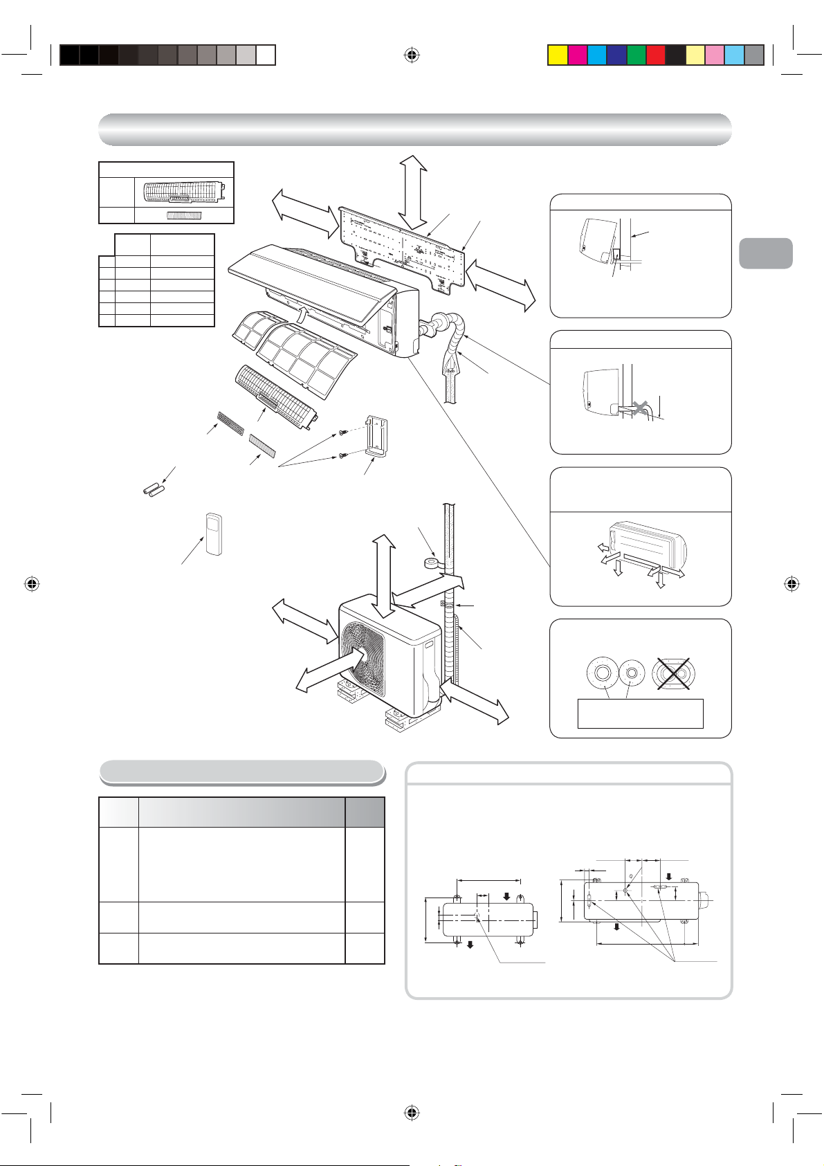
Remark :
• Detail of accessory and installation parts can see in the accessory
sheet.
• Some pictures might be different from the actual parts.
Air
lter
)
D mm or more
Hook
Remote control holder
4
Vinyl tape
Apply after carrying
out a drainage test.
C mm or more
A mm or more
E mm or more
Hook
Extension
drain hose
(Not available,
provided by installer)
C mm or more
Installation
1
plate
B mm or more
Shield pipe
Saddle
For the rear left and left piping
Wall
Insert the cushion between the indoor
unit and wall, and tilt the indoor unit for
better operation.
Do not allow the drain hose to get slack.
Cut the piping
hole sloped
slightly.
Make sure to run the drain hose sloped
downward.
The auxiliary piping can be connected to
the left, rear left, rear right, right, bottom
right or bottom left.
Right
Rear
right
Rear
Bottom
left
right
Insulate the refrigerant pipes separately
with insulation, not together.
6 mm thick heat resisting
polyethylene foam
Left
Bottom left
EN
ES
FR
IT
DE
PT
PL
CZ
RU
CR
HU
TR
NL
GR
SV
Part
code
A
B
C
1110251155-EN.indd 2
Optional Installation Parts
Parts name Q’ty
Refrigerant piping
Liquid side : Ø6.35 mm
Gas side : Ø9.52 mm
(10(7)~13(7) SKV Series)
: Ø12.70 mm
(16(7) SKV Series)
Pipe insulating material
(polyethylene foam, 6 mm thick)
Putty, PVC tapes
One
each
1
One
each
Fixing bolt arrangement of outdoor unit
• Secure the outdoor unit with xing bolts and nuts if the unit is likely to be
exposed to a strong wind.
• Use Ø8 mm or Ø10 mm anchor bolts and nuts.
• If it is necessary to drain the defrost water, attach drain nipple 9 and cap
water proof ! to the bottom plate of the outdoor unit before installing it.
2
280 mm
53 mm
Air outlet
10(7)SAV Series
97 mm
500 mm
Air inlet
Drain outlet
320 mm
7 mm
32.5 mm
108 mm
86 mm
Air outlet
10SAVR
13(7)~16(7)SAV Series
600 mm
125 mm
Air inlet
30
102 mm
90 mm
Drain outlet
12/18/07 3:47:20 PM
FI
NO
DK
RO
BG
EE
LV
SK
SI
INDOOR UNIT
INDOOR UNIT
1110251155-EN.indd 3
12/18/07 3:47:22 PM
Installation Place
• A place which provides the spaces around the indoor unit as shown in the
diagram
• A place where there are no obstacles near the air inlet and outlet
• A place which allows easy installation of the piping to the outdoor unit
• A place which allows the front panel to be opened
• The indoor unit shall be installed as top of the indoor unit comes to at least
2 m height. Also, it must be avoided to put anything on the top of the indoor
unit.
CAUTION
• Direct sunlight to the indoor unit’s wireless receiver should be avoided.
• The microprocessor in the indoor unit should not be too close to RF
noise sources.
(For details, see the owner’s manual.)
Remote control
• A place where there are no obstacles such as a curtain that may block the
signal from the indoor unit
• Do not install the remote control in a place exposed to direct sunlight or close
to a heating source such as a stove.
• Keep the remote control at least 1 m apart from the nearest TV set or stereo
equipment. (This is necessary to prevent image disturbances or noise
interference.)
• The location of the remote control should be determined as shown below.
(Side view) (Top view)
Indoor unit
5
7
Reception
range
Indoor unit
°
Remote
control
Reception range
54
5°
°
4
Remote
control
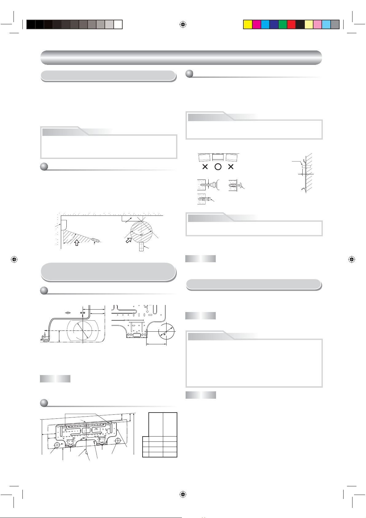
Cutting a Hole and Mounting
Installation Plate
Cutting a hole
When installing the refrigerant pipes from the rear
90 mm
66 mm
80 100 180
Ø65 mm
Pipe hole
42 mm
The center of the pipe hole is above the arrow.
10(7)SKV
The center of the pipe hole
is above the arrow.
13(7)~16(7)SKV(R)
1. After determining the pipe hole position on the mounting plate (¨), drill the
pipe hole (Ø65 mm) at a slight downward slant to the outdoor side.
NOTE
• When drilling a wall that contains a metal lath, wire lath or metal plate, be sure
to use a pipe hole brim ring sold separately.
Mounting the installation plate
Anchor bolt holes
Hook
A
B
Pipe hole
65 mm
100 mm
10SKVR
When the installation plate is directly mounted
on the wall
1. Securely t the installation plate onto the wall by screwing it in the upper and
lower parts to hook up the indoor unit.
2. To mount the installation plate on a concrete wall with anchor bolts, use the
anchor bolt holes as illustrated in the below gure.
3. Install the installation plate horizontally in the wall.
CAUTION
When installing the installation plate with a mounting screw, do not use the
anchor bolt holes. Otherwise, the unit may fall down and result in personal
injury and property damage.
Installation plate
(Keep horizontal direction.)
Anchor bolt
Projection
5 mm dia. hole
Clip anchor
(local parts)
7
Mounting screw
Ø4 x 25 R
15 mm or less
CAUTION
Failure to rmly install the unit may result in personal injury and property
damage if the unit falls.
• In case of block, brick, concrete or similar type walls, make 5 mm dia. holes
in the wall.
• Insert clip anchors for appropriate mounting screws 7.
NOTE
• Secure four corners and lower parts of the installation plate with 4 to 6
mounting screws to install it.
Electrical Work
1. The supply voltage must be the same as the rated voltage of the air conditioner.
2. Prepare the power source for exclusive use with the air conditioner.
NOTE
• Wire type : More than H07RN-F or 245 IEC66
CAUTION
• This appliance can be connected to the mains in either of the following
two ways.
(1) Connection to xed wiring:
A switch or circuit breaker which disconnects all poles and has a
contact separation of at least 3 mm must be incorporated in the xed
wiring. An approved circuit breaker or switches must be used.
(2) Connection with power supply plug:
Attach power supply plug with power cord and plug it into wall outlet.
An approved power supply cord and plug must be used.
NOTE
• Perform wiring works so as to allow a general wiring capacity.
C
D
Pipe hole
Indoor unit
1110251155-EN.indd 3
Hook
Thread
Weight
Hook
Pipe hole
7
Mounting screw
1
Installation
plate
10SKV
A 35 mm 62 mm
B 55.5 mm 82.5 mm
2 m or more from oor
C 120 mm 170 mm
D 65 mm 85 mm
107SKV
10~16SKV(R)
137, 167SKV
3
12/18/07 3:47:22 PM

Wiring Connection
1110251155-EN.indd 4
12/18/07 3:47:24 PM
How to connect the connecting cable
Wiring of the connecting cable can be carried out without removing the
front panel.
1. Remove the air inlet grille.
Open the air inlet grille upward and pull it toward you.
2. Remove the terminal cover and cord clamp.
3. Insert the connecting cable (according to the local cords) into the pipe hole
on the wall.
4. Take out the connecting cable through the cable slot on the rear panel so
that it protrudes about 15 cm from the front.
5. Insert the connecting cable fully into the terminal block and secure it tightly
with screws.
6. Tightening torque : 1.2 N·m (0.12 kgf·m)
7. Secure the connecting cable with the cord clamp.
8. Fix the terminal cover, rear plate bushing and air inlet grille on the indoor
unit.
CAUTION
• Be sure to refer to the wiring system diagram labeled inside the front
panel.
• Check local electrical cords and also any speci c wiring instructions or
limitations.
Cord clamp
Terminal cover
Screw
Screw
Connecting cable
about 15 cm
Stripping length of the connecting cable
1
Screw
NOTE
• Use stranded wire only.
• Wire type : H07RN-F or more
How to install the air inlet grille on the indoor
unit
• When attaching the air inlet grille,
the contrary of the removed
operation is performed.
2
3
10 mm
Terminal block
1
2
3
Earth line
Connecting cable
110 mm
10 mm
50 mm
Earth line
1. Die-cutting front panel slit
Cut out the slit on the leftward or right side of the front panel for the left or
right connection and the slit on the bottom left or right side of the front panel
for the bottom left or right connection with a pair of nippers.
2. Changing drain hose
For leftward connection, bottom-leftward connection and rearleftward
connection’s piping, it is necessary to change the drain hose and drain
cap.
How to remove the drain hose
• The drain hose can be removed by removing the
screw securing the drain hose and then pulling out
the drain hose.
• When removing the drain hose, be careful of any
sharp edges of steel plate. The edges can injuries.
• To install the drain hose, insert the drain hose
rmly until the connection part contacts with heat
insulator, and the secure it with original screw.
How to remove the drain cap
Clip the drain cap by needlenose pliers and pull out.
How to x the drain cap
1) Insert hexagon
wrench (4 mm)
in a center head.
2) Firmly insert the drain cap.
No gap
Insert a hexagon
wrench (4 mm).
4 mm
Do not apply lubricating oil
(refrigerant machine oil) when
inserting the drain cap. Application
causes deterioration and drain
leakage of the plug.
Heat insulator
Drain hose
CAUTION
Firmly insert the drain hose and drain cap; otherwise, water may leak.
In case of right or left piping
• After scribing slits of the front panel with a
knife or a making-off pin, cut them with a
pair of nippers or an equivalent tool.
Slit
In case of bottom right or bottom left piping
• After scribing slits of the front panel with a
knife or a making-off pin, cut them with a
pair of nippers or an equivalent tool.
Slit
EN
ES
FR
IT
DE
PT
PL
CZ
RU
CR
HU
TR
NL
GR
SV
FI
Piping and Drain Hose Installation
Piping and drain hose forming
* Since dewing results in a machine trouble, make sure to insulate both con-
necting pipes. (Use polyethylene foam as insulating material.)
Rear right
Rear left
Bottom left
Left
Bottom right
Right
1110251155-EN.indd 4
tils le
gnittu
na
p
c-eiD
t
n
o
rf
esoh ni
g
nign
ahC
ard
Left-hand connection with piping
• Bend the connecting pipe so that it is laid within 43 mm above the wall surface. If the connecting pipe is laid exceeding 43 mm above the wall surface,
the indoor unit may unstably be set on the wall.
When bending the connecting pipe, make sure to use a spring bender so as
not to crush the pipe.
NO
DK
RO
Bend the connecting pipe within a radius of 30 mm.
To connect the pipe after installation of the unit ( gure)
no
itar
aperp g
ni
pi
P
B mm
m
m 3
4
(To the forefront of are)
A mm
Gas side
Liquid side
Outward form of indoor unit
R 30 mm (Use polisin (polyethylene)
core or the like for bending pipe.)
80
Use the handle of screwdriver, etc.
10(7)SKV
A 270 270
B 170 230
BG
EE
10SKVR
LV
13(7)~16(7)SKV(R)
SK
SI
4
12/18/07 3:47:24 PM
 Loading...