


FILE NO. A00-0001
SUPPLEMENT
SERVICE MANUAL
AIR-CONDITIONER
SPLIT WALL TYPE
RAS-18YKH-E / RAS-18YAH-E RAS-18YKH-A / RAS-18YAH-A
PRINTED IN THAILAND, Apr.,2000
CONTENTS
1. |
SPECIFICATIONS ....................................................................................... |
3 |
2. |
CONSTRUCTION VIEWS............................................................................ |
5 |
3. |
WIRING DIAGRAM ..................................................................................... |
7 |
4. |
SPECIFICATIONS OF ELECTRICAL PARTS ............................................ |
8 |
5. |
REFRIGERANT CYCLE DIAGRAM ............................................................ |
9 |
6. |
CONTROL BLOCK DIAGRAM ................................................................. |
10 |
7. |
OPERATION DESCRIPTION .................................................................... |
12 |
8. |
INSTALLATION PROCEDURE ................................................................. |
16 |
9. |
TROUBLESHOOTING CHART ................................................................. |
20 |
10. |
EXPLODED VIEWS AND PARTS LIST .................................................... |
37 |
– 2 –

1. SPECIFICATIONS
|
|
|
|
|
Model |
RAS-18YKH-E, RAS-18YAH-E |
RAS-18YKH-A, RAS-18YAH-A |
||
Item |
|
|
|
|
Cooling |
Heating |
Cooling |
Heating |
|
Capacity |
|
|
|
|
*1 (kW) |
220–240V |
240V |
|
|
|
|
|
|
5,0 |
6,35–6,50 |
5,0 |
6,50 |
||
|
|
|
|
|
|
||||
|
|
|
|
|
Phase |
|
Single |
|
|
|
|
|
|
|
|
|
|
|
|
Power source |
|
|
|
|
(V) |
220–240V |
240V |
|
|
|
|
|
|
|
(Hz) |
|
|
50 |
|
Power consumption |
|
|
|
|
(kW) |
2,03–2,20 |
2,33–2,52 |
2,20 |
2,52 |
Power factor |
|
|
|
|
(%) |
91–81 |
92–85 |
81 |
85 |
Running current |
Indoor |
|
|
|
(A) |
0,28–0,30 |
0,28–0,30 |
0,30 |
0,30 |
Outdoor |
|
|
|
(A) |
9,82–11,00 |
11,22–12,10 |
11,00 |
12,10 |
|
|
|
|
|
||||||
Starting current |
|
|
|
|
(A) |
|
|
60 |
|
Moisture removal |
|
|
|
|
(lit/h) |
|
|
2,0 |
|
Noise |
Indoor (H/M/L) |
|
|
|
(dB) |
|
44/41/38 |
|
|
Outdoor |
|
|
|
(dB) |
54–56 |
55–57 |
56 |
57 |
|
|
|
|
|
||||||
Refrigerant |
Name of refrigerant |
|
|
R-22 |
|
||||
Rated volume |
|
|
|
(kg) |
|
1,45 |
|
||
|
|
|
|
|
|
||||
Refrigerant control |
|
|
|
|
|
|
Capillary tube |
|
|
|
Gas side size |
|
|
|
(mm) |
|
12,7 |
|
|
|
Connection type |
|
|
|
|
|
Flare connection |
|
|
|
Liquid side size |
|
|
|
(mm) |
|
6,35 |
|
|
Interconnection pipe |
Connection type |
|
|
|
|
|
Flare connection |
|
|
Maximum length (of one way) *2 (m) |
|
|
15 |
|
|||||
|
|
|
|
||||||
|
Maximum height difference |
|
|
|
6 |
|
|||
|
Indoor unit |
|
|
|
|
|
|
|
|
|
− |
(m) |
|
|
|
||||
|
|
|
|
|
|||||
|
Outdoor unit |
↓ |
|
|
|
|
|||
|
|
|
|
|
|
||||
Codensate drain pipe |
Outer diameter |
|
|
|
(mm) |
|
|
16 |
|
INDOOR UNIT |
|
|
|
|
|
|
RAS-18YKH-E / RAS-18YKH-A |
|
|
|
Height |
|
|
|
(mm) |
|
298 |
|
|
|
|
|
|
|
|
|
|
|
|
Dimension |
Width |
|
|
|
(mm) |
|
1050 |
|
|
|
Depth |
|
|
|
(mm) |
|
180 |
|
|
Net weight |
|
|
|
|
(kg) |
|
|
12 |
|
Evaporator type |
|
|
|
|
|
|
Finned tube |
|
|
|
|
|
|
|
|
|
|
|
|
Indoor fan type |
|
|
|
|
|
|
Cross flow fan |
|
|
|
High fan |
|
|
|
(m³/h) |
|
750 |
|
|
Air volume |
Medium fan |
|
|
|
(m³/h) |
|
650 |
|
|
|
Low fan |
|
|
|
(m³/h) |
|
550 |
|
|
Fan motor output |
|
|
|
|
(W) |
|
|
31 |
|
Air filter |
|
|
|
|
|
|
Polypropylene net filter (Washable) |
|
|
OUTDOOR UNIT |
|
|
|
|
|
RAS-18YAH-E |
RAS-18YAH-A |
||
|
Height |
|
|
|
(mm) |
|
690 |
|
|
Dimension |
Width |
|
|
|
(mm) |
|
880 |
|
|
|
Depth |
|
|
|
(mm) |
|
310 |
|
|
Net weight |
|
|
|
|
(kg) |
|
|
65 |
|
Condenser type |
|
|
|
|
|
|
Finned tube |
|
|
Outdoor fan type |
|
|
|
|
|
|
Propeller |
|
|
Airflow volume |
|
|
|
|
(m³/h) |
220V |
240V |
240V |
|
|
|
|
|
3380 |
3560 |
3560 |
|
||
|
|
|
|
|
|
|
|||
Fan motor output |
|
|
|
|
(W) |
|
|
65 |
|
Compressor |
Model |
|
|
|
|
|
PH280X3-4MS |
|
|
Output |
|
|
|
(W) |
|
2000 |
|
||
|
|
|
|
|
|
||||
Safety device |
|
|
|
|
|
|
Fuse, overload relay |
|
|
Auto louver |
|
|
|
|
|
|
|
Yes |
|
Usable outdoor temperature range |
|
|
|
(°C) |
11 to 43 |
–10 to 21 |
11 to 43 |
–10 to 21 |
|
Specifications are subject to change without notice.
– 3 –

Note : *1
• Capacity is based on the following temperature conditions.
|
Condition |
|
JIS C9612-1994 |
|
Temperature |
Cooling |
Heating |
|
(DB) |
27°C |
20°C |
Indoor unit inlet air temperature |
|
|
|
|
(WB) |
19°C |
— |
|
(DB) |
35°C |
7°C |
Outdoor unit inlet air temperature |
|
|
|
|
(WB) |
24°C |
6°C |
Notes : *2 |
CHARGELESS |
|
|
•No additional refrigerant required.
•This air conditioner accepts a connection piping length of up to 15m and a head of up to 6m.
•There is no need to add the refrigerant as long as the total length of the connection piping is up to 15m.
– 4 –
2. |
CONSTRUCTION VIEWS |
|
||||||||||||||||
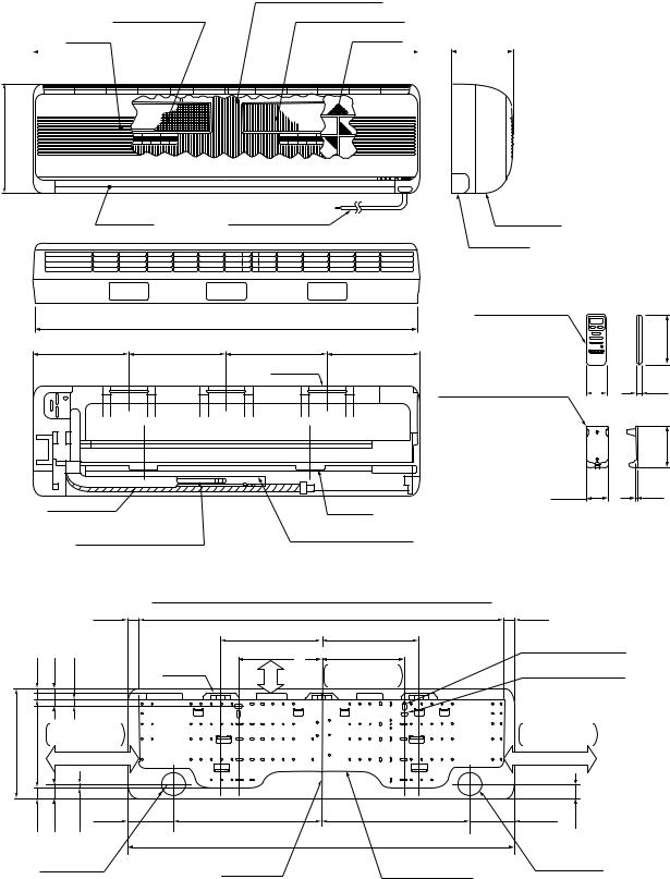
2-1. Indoor Unit |
|
|
|
|
|
|
||||||||||||
RAS-18YKH-E, RAS-18YKH-A |
|
|
|
|
|
|
||||||||||||
|
|
|
|
|
|
|
|
|
|
|
|
|
Indoor heat exchanger |
|
||||
|
|
Deodorizing filter |
Dust collecting filter |
|
||||||||||||||
|
|
Air inlet |
Air filter |
|
||||||||||||||
|
|
|
|
|
|
|
|
|
|
|
|
|
1050 |
|
|
|
|
180 |
|
|
|
|
|
|
|
|
|
|
|
|
|
|
|||||
|
|
|
|
|
|
|
|
|
|
|
|
|
|
|
|
|
|
|
|
|
|
|
|
|
|
|
|
|
|
|
|
|
|
|
|
|
|
298
|
Air outlet |
Power cord (1,7m) |
Front panel |
|
|
|
|
Rear plate |
|
|
|
|
Wireless |
|
|
|
1040 |
remote control |
|
261 |
264 |
274 |
251 |
|
|
|
Hanger |
|
|
|
|
|
Remote control holder |
55 |
59.6
Drain hose |
Hanger |
|
0,60m |
||
|
||
Auxiliary pipe (0,39m) |
Auxiliary pipe (0,49m) |
|
Flare Ø12,7 |
Flare Ø6,35 |
Detail of installing dimensions of the indoor unit
|
|
|
30 |
|
990 |
15 |
40 |
20 |
274 |
44 moreor |
264 |
|
from ceiling |
||||
|
|
|
|
|
450 |
|
|
|
Hanger |
|
Minimum distance |
298 |
248 |
Minimum distance |
|
from wall |
|||
|
|
80 or more
30 |
40 |
10 |
123 |
402 |
402 |
|
|
|
|||
|
|
|
|
|
1050 |
30
Anchor bolt hole
Ø8 ~ Ø10 Anchor bolt hole
Ø6
Minimum distance from wall
130 or more
123 |
47 |
Ø65 |
Center line |
Installation plate |
Ø65 |
|
Piping hole |
Piping hole |
|||
|
|
136
16
112.8
5
– 5 –
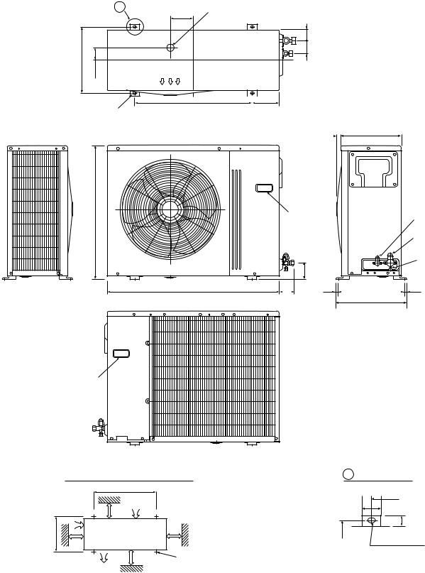
2-2. Outdoor Unit
RAS-18YAH-E, RAS-18YAH-A
|
A |
Ø25 Drain outlet |
|
|
120 |
340 |
|
68 52 |
63,8 |
|
600
4–Ø12 x 18 hole
(for Ø8–Ø10 anchor bolt)
690
880
 140
140
23 310
Electric
Parts cover
Handle
Liquid side (Flare Ø6,35)
Gas side (Flare Ø15,88)
Service port |
88 |
74 |
12 |
340 (pitch) |
12 |
364
Handle
Mounting dimension of anchor bolt
|
|
600 |
|
100 or more |
Air inlet |
||
600 or more |
|||
|
|
||
340 |
Air inlet |
|
|
|
|
||
100 or more |
600 or more 4 x Ø12 x 18 for Ø8–Ø10 anchor bolt |
||
|
Air outlet |
|
|
|
A Detail Drawing |
|
600 |
|
50 |
340 |
27 |
Ø12 x 18 hole
– 6 –

3. WIRING DIAGRAM
COLOR
IDENTIFICATION
BRW : BROWN
RED : RED
WHI : WHITE YEL : YELLOW BLU : BLUE BLK : BLACK GRY : GRAY PNK : PINK ORN : ORANGE
GRN & YEL : GREEN & ORANGE
Switch parts |
|
|||
CN16 |
1 |
2 |
3 |
CN25 |
|
|
|
|
|
|
WHI |
BLU |
BLU |
|
|
1 |
2 |
3 |
|
|
1 |
2 |
3 |
|
|
CN15 |
|
||
|
F01 Fuse |
|
||
|
|
T5A |
|
|
|
|
250V |
|
|
CN03
1 |
3 |
5 |
1 |
3 |
5 |
|
GRN |
RED |
|
& |
|
BLK WHI YEL |
3 |
|
1 |
2 |
|
Grand terminal
Indoor terminal block
|
|
|
|
|
|
|
|
|
|
Louver |
|
|
|
|
|
|
|
|
|
Thermal fuse |
|||
|
Indication parts |
|
|
motor |
|
|
|
|
|
|
|
|
|
|
|||||||||
|
|
|
|
|
|
|
|
|
|
|
|
|
164˚C |
|
|
||||||||
1 2 3 4 5 |
6 |
7 |
8 |
9 |
|
|
|
|
|
|
|
|
|
|
|
|
|
|
Fan motor |
||||
1 |
2 |
3 |
4 |
5 |
6 |
7 |
8 |
9 |
|
|
|
|
PNK |
YEL ORN |
RED |
BRW |
|
|
|
|
|
|
|
WHI |
BRW BRW BRW |
BRW |
BRW |
BRW |
BRW |
BRW |
|
|
|
BLU |
|
|
|
|
|
|
|||||||
1 |
2 |
3 |
4 |
5 |
6 |
7 |
8 |
9 |
|
|
|
6 |
5 |
4 |
3 |
2 |
1 |
|
|
|
|
|
IC |
1 |
2 |
3 |
4 |
5 |
6 |
7 |
8 |
9 |
|
|
|
6 |
5 |
4 |
3 |
2 |
1 |
|
|
|
|
|
|
|
|
|
|
|
|
|
|
|
|||||||||||||||
|
|
|
CN24 |
|
|
|
|
|
|
|
|
CN10 |
|
|
|
|
YEL |
|
|
||||
|
|
|
|
|
|
|
|
|
|
|
|
|
|
|
|
CN13 |
1 |
1 |
|
|
|||
|
|
|
|
|
|
|
|
|
|
|
TNR R98 |
|
|
GRY |
|
|
|||||||
|
|
|
|
|
|
|
|
|
CR01 |
|
|
C26 |
|
2 2 |
|
|
|||||||
|
|
|
|
|
|
|
|
|
|
|
|
BRW |
|
|
|||||||||
|
|
|
|
|
|
L01 |
|
|
|
|
|
|
|
3 |
3 |
|
|
||||||
|
|
|
|
|
|
|
TRIAC D04 |
|
|
|
Running |
|
|
|
|||||||||
|
|
|
|
C28 |
Filter |
|
|
|
capacity |
|
|
WHI |
|
|
|||||||||
|
|
|
|
|
|
|
|
|
|
|
|
|
|
|
|
|
5 |
5 |
|
|
|||
|
|
|
|
|
|
|
|
|
|
|
|
|
|
|
|
|
|
|
|
|
|
||
TNR |
|
|
|
|
|
|
|
|
|
|
|
|
|
|
|
|
|
3 |
3 |
BLK |
|
|
|
R106 |
|
|
|
|
|
|
|
|
|
|
|
|
|
|
|
|
|
|
|
|
|||
|
|
|
|
|
|
|
|
|
|
|
|
|
|
|
|
|
|
|
|
|
|
||
|
|
|
|
|
|
|
|
|
|
|
|
|
|
|
|
|
|
|
1 |
1 |
RED |
|
|
|
|
|
|
|
|
|
|
C27 |
|
|
|
|
TH01 |
|
CN07 |
T01 |
Transformer |
||||||
|
|
|
|
|
|
|
|
|
|
|
|
|
|
|
|
|
|
|
|||||
|
|
|
|
|
|
|
|
|
|
|
|
|
|
|
|
|
|
|
3 |
3 |
WHI 3 3 |
1 1 |
|
|
|
|
|
|
|
|
|
|
|
|
|
|
PTH |
|
|
|
|
|
|
RED 1 1 |
2 |
||
|
|
|
|
|
|
|
|
|
|
|
|
|
|
|
|
|
1 1 |
3 3 |
|||||
|
|
|
|
|
|
|
|
|
|
|
|
|
|
|
|
CN12 |
|||||||
|
|
MAIN P.C. BOARD (MCC-1293) |
|
|
|
CN32 |
CN33 |
||||||||||||||||
|
|
|
|
|
|
|
|
||||||||||||||||
|
|
|
|
|
|
|
|
|
|
|
|
|
|
|
|
|
|
|
3 3 |
GRY |
MCC-629 |
||
|
|
|
|
|
|
|
|
|
|
|
|
|
|
|
|
|
|
|
|
|
|||
|
|
|
|
|
|
|
|
|
|
|
|
|
|
|
|
CN01 |
2 |
|
BLU |
|
|
||
|
CN17 |
|
|
CN26 |
CN04 |
CN05 |
|
|
CN22 |
|
1 1 |
|
|
||||||||||
|
|
|
|
|
|
|
|
|
|
|
|||||||||||||
|
1 |
2 |
|
3 |
|
|
1 |
2 |
1 |
2 |
1 |
2 |
|
|
|
1 |
2 |
|
|
|
|
|
|
|
1 |
2 |
|
3 |
|
|
1 |
2 |
1 |
2 |
1 |
2 |
|
|
|
1 |
2 |
|
|
|
|
|
|
|
RED |
WHI |
BLK |
|
|
ORN |
ORN |
BLK |
BLK |
BLK |
BLK |
|
|
|
WHI |
BLU |
|
|
|
|
|
|
|
|
1 |
2 |
|
3 |
PJ18 |
|
|
|
|
|
|
|
|
|
|
|
|
|
|
|
|
|
|
|
1 |
2 |
|
3 |
|
|
|
|
|
|
|
|
|
1 |
2 |
CN30 |
|
|
|
||||
Infrared rays |
|
|
|
|
|
|
|
|
|
Buzzer |
|
|
|
|
|
|
|||||||
receive parts Thermal fuse |
Thetmo. Heat exchanger |
|
parts |
|
|
|
|
|
|
||||||||||||||
|
|
|
|
|
|
|
77˚C |
sensor |
sensor |
|
|
|
|
|
|
|
|
|
|
||||
Outdoor terminal block |
|
|
|
|
Transformer |
|
|
|
|
|
|
|
|
|||
Power supply |
|
|
|
|
|
|
|
|
|
|
|
|
|
|
||
|
|
|
|
|
|
|
|
1 |
1 |
MAIN P.C. BOARD (MCC-1275) |
|
|
|
|||
18YAH-E : 220–240V ~, 50Hz |
|
|
|
|
|
BLU |
|
|
|
|||||||
18YAH-A : 240V ~, 50Hz |
|
|
|
|
|
|
|
2 |
CN06 |
|
|
|
|
Discharge |
||
|
|
|
|
|
|
|
|
YEL |
3 |
3 |
|
|
|
|
|
temperature |
|
|
|
|
|
|
|
|
|
|
|
|
|
|
|
sensor (TD) |
|
L |
N |
|
1 |
2 |
3 |
|
|
RED 1 |
|
|
|
|
|
|
||
|
|
|
1 |
|
|
|
|
1 1 |
BLK |
|||||||
|
Ferrite core |
|
|
|
|
|
|
|
|
CN05 |
|
|
CN11 |
2 |
||
|
|
|
|
|
|
WHI 3 |
3 |
|
|
|
||||||
BLK |
|
|
|
|
|
|
TNR R74 |
|
DSA |
|
3 3 |
BLK |
||||
|
|
|
|
|
GRN & YEL |
|
|
|
|
|
|
|||||
|
RED GRN & YEL |
|
|
|
|
BLK 1 |
1 |
|
|
|
|
|||||
|
|
|
|
|
|
|
|
|
|
|
Heat |
|||||
|
|
|
|
|
Chassis |
BLK |
|
|
|
|
|
|
|
exchanger |
||
BLK RED |
|
|
|
|
|
|
3 |
3 |
T5A, 250V AC |
|
|
sensor (TE) |
||||
|
|
|
|
|
|
WHI |
|
|
|
1 1 |
BLK |
|||||
|
|
|
|
|
|
|
|
5 |
5 |
|
|
TNR |
|
|||
|
|
|
|
|
|
|
|
|
CN01 |
|
R73 |
CN11 |
2 |
|
||
|
|
|
|
|
|
|
|
RED 7 |
7 |
|
|
|
|
3 3 BLK |
||
|
|
|
|
|
|
|
|
GRY 9 |
9 |
|
|
|
|
|
|
|
|
RED |
|
|
|
|
|
|
|
1 |
1 |
|
|
|
|
|
|
Crank case |
|
|
|
|
|
|
|
|
|
|
|
|
|
|
|
|
|
|
|
Magnetic |
|
|
|
|
|
|
|
|
|
|
|
||
heater |
Fuse |
|
|
|
|
|
3 |
3 |
|
|
|
|
|
|
||
BLK |
|
relay |
|
|
|
CN04 |
|
|
|
|
|
|||||
|
3A |
|
|
|
|
|
|
|
|
|
|
|
||||
1 |
1 |
21 |
5L3 |
|
3L2 |
1L1 |
A1 |
|
|
5 |
CR11 |
|
|
|
|
|
2 |
2 |
|
|
|
|
|
|
|
|
|||||||
|
|
|
|
|
52C |
|
|
|
|
|
|
|
|
|||
|
Fuse |
|
|
|
|
|
BLU 1 |
|
|
|
|
|
|
|
||
|
22 |
6T3 |
|
4T2 |
2T1 |
A2 |
1 |
|
|
|
|
|
|
|||
|
3A |
|
CN11 |
RY07 |
|
|
|
|
||||||||
|
BLK |
|
|
|
|
|
|
YEL |
|
|
|
|
|
|
|
|
|
Capacitor |
|
|
|
Capacitor |
3 |
3 |
|
|
|
|
|
|
|||
|
|
|
|
|
|
|
|
|
|
|
|
|
|
|||
|
RED |
|
|
|
RED |
|
|
BLK 1 |
1 |
|
RY05 |
TNR R96 |
|
|
|
|
|
|
|
|
|
|
|
|
|
|
|
CN02 |
|
|
|
|
|
|
|
|
|
|
|
|
|
BLK |
|
|
|
|
|
|
|
|
|
WHI |
|
|
|
WHI |
|
|
3 |
3 |
CR12 |
|
|
|
|
|
|
|
|
|
|
|
Coil for |
|
|
|
|
|
|
|
||||
|
PNK |
|
|
|
RED |
|
4-way valve |
|
|
|
|
|
|
|
|
|
|
|
BLK |
|
|
BLK |
BLU 1 |
1 |
|
|
|
|
|
|
|||
|
|
|
|
|
|
CN03 |
|
IC07 |
|
|
|
|||||
|
Compressor |
|
|
Fan motor |
|
|
|
|
|
|
|
|||||
|
|
|
|
|
3 |
|
|
|
|
|
||||||
|
|
|
|
|
|
|
|
|
|
|
||||||
|
|
|
|
|
|
|
|
|
|
– 7 – |
|
|
|
|
|
|
4. SPECIFICATIONS OF ELECTRICAL PARTS
4-1. Indoor Unit
RAS-18YKH-E, RAS-18YKH-A
No. |
Parts name |
Type |
|
Specifications |
|
|
|
|
|
|
|
|
|
|
|
|
Output (Rated) 31W, 2poles, DC35V, 19W |
|
||
|
|
|
|
|
|
|
1 |
Fan motor (for indoor) |
AFP-220-31-4B |
Winding resistance (Ω) |
Red-Black |
|
White-Black |
|
|
|
(at 20°C) |
267,8 |
|
147,7 |
|
|
|
|
|
||
|
|
|
|
|
|
|
2 |
Thermo. sensor (TA-sensor) |
(microprocessor) |
10kΩ at 25°C |
|
|
|
|
|
|
|
|
|
|
3 |
Transformer (T01) |
TTZ |
MCC-629 |
|
|
|
|
|
|
|
|
|
|
4 |
Microcomputer |
TMP87CK40AN |
|
|
|
|
|
|
|
|
|
|
|
5 |
Heat exchanger sensor |
(microprocessor) |
10kΩ at 25°C |
|
|
|
|
(TC-sensor) |
|
|
|
|
|
|
|
|
|
|
|
|
6 |
Line filter (L01) |
|
25mH, AC 0,7A |
|
|
|
|
|
|
|
|
|
|
7 |
Diode (DB01) |
KBP06M |
|
|
|
|
|
|
|
|
|
|
|
8 |
Capacitor (C01) |
ECAIEHG222E |
220µF, 25V |
|
|
|
|
|
|
|
|
|
|
9 |
Fuse (F01) |
MT3 |
T5A, 250V |
|
|
|
|
|
|
|
|
|
|
10 |
Varistor (R98, R106) |
15G431K |
430V |
|
|
|
|
|
|
|
|
|
|
11 |
PTH (TH01) |
|
82Ω |
|
|
|
|
|
|
|
|
|
|
12 |
Louver motor |
MP35EA7 |
Output (Rated) 2W, 10poles, 1phase DC12V |
|||
|
|
|
|
|
|
|
4-2. Outdoor Unit
RAS-18YAH-E, RAS-18YAH-A
No. |
Parts name |
Type |
|
|
Specifications |
|
|
|
|
|
|
|
|
|
|
|
Output (Rated) 2000W, 2poles, 1phase, 220–240V, 50Hz |
|||
|
|
|
|
|
|
|
1 |
Compressor |
PH280X3-4MS |
Ω |
) |
Red-Black |
White-Black |
|
|
|
Winding resistance ( |
|
|
|
|
|
|
(at 20°C) |
|
1,35 |
2,68 |
|
|
|
|
|
||
|
|
|
|
|
|
|
|
|
|
Output (Rated) 65W, 6poles, 1phase, 220–240V, 50Hz |
|||
|
|
|
|
|
|
|
2 |
Fan motor (for outdoor) |
MMF-230-65C |
Ω |
) |
Red-Black |
White-Black |
|
|
|
Winding resistance ( |
|
|
|
|
|
|
(at 20°C) |
|
71,2 |
139,0 |
|
|
|
|
|
||
|
|
|
|
|
|
|
3 |
Running capacitor (for fan motor) |
SK45FMP |
AC 450V, 3,5µF |
|
|
|
|
|
|
|
|
|
|
4 |
Running capacitor |
SK42CMP45U1 |
AC 420V, 45µF |
|
|
|
|
(for compressor) |
|
|
|
|
|
|
|
|
|
|
|
|
5 |
Solenoid coil (for 4-way valve) |
LB60012 |
AC 200/240V |
|
|
|
|
|
|
|
|
|
|
6 |
Thermo. sensor |
TE, TD |
10kΩ at 25°C |
|
|
|
|
|
|
|
|
|
|
7 |
Case heater |
|
240V, 28W |
|
|
|
|
|
|
|
|
|
|
8 |
Magnetic switch |
FC2S |
3a1b |
|
|
|
|
|
|
|
|
|
|
9 |
Transformer |
FT67 |
220–240V |
|
|
|
|
|
|
|
|
|
|
10 |
Microcomputer |
TMP470840 |
|
|
|
|
|
|
|
|
|
|
|
11 |
Varistor (R73, 74, 86) |
15G471K |
470V |
|
|
|
|
|
|
|
|
|
|
12 |
Fuse (F01) |
MT3 |
T5A, 250V |
|
|
|
|
|
|
|
|
|
|
– 8 –

|
5. REFRIGERANT CYCLE DIAGRAM |
|
|
|
|
|
INDOOR UNIT A |
(Note) |
|
|
T1 |
Indoor heat |
|
|
|
Maximum pipe length is 15m |
|||
|
|
exchanger |
||
|
Cooling |
Maximum pipe head is |
6m |
|
|
|
|||
|
|
|
|
|
0,39m |
Heating |
|
0,49m |
|
(Connecting pipe) |
|
(Connecting pipe) |
||
|
|
|||
Ø12,7 |
|
|
Ø6,35 |
|
|
|
Cross flow fan |
|
|
O.D. : 12,7mm |
|
|
O.D. : 6,35mm |
|
P |
|
|
|
Packed valve |
Packed valve |
|
|
(Ø12,7) |
(Ø6,35) |
|
|
Gas container connection (Reinstall etc.) |
|
|
Cooling |
Heating |
|
|
|
|
Liquid tank |
|
|
4-way valve |
550cc |
|
|
|
|
|
Heating |
Cooling |
Compressor |
|
PH280X3-4MS |
|
||
|
|
Capillary tube |
Capillary tube |
|
|
Ø1,7 x 600 |
Ø1,2 x 700 |
|
|
|
|
|
Accumulator |
|
|
|
|
|
|
|
|
|
|
|
|
|
|
||||
|
|
|
|
|
|
|
Outdoor heat exchanger |
|
|
|
|
|
|
||||||||||
|
|
|
|
|
|
|
|
|
|
|
|
|
|||||||||||
|
|
|
|
|
|
|
|
|
|
|
|
|
|
|
|
|
|
|
|
|
Refrigerant |
||
|
|
|
|
|
|
|
|
|
|
|
|
|
|
|
|
|
|
|
|
|
|||
|
|
|
|
|
|
|
|
|
|
|
|
|
|
|
|
|
|
|
|
|
|||
|
|
|
|
|
|
|
|
|
|
|
|
|
|
|
|
|
|
|
|
|
|||
|
|
|
|
|
|
|
|
|
|
Propeller fan |
|
|
|
|
|
|
|
R-22 1,45kg |
|||||
|
|
|
|
Cooling |
|
|
|
OUTDOOR UNIT |
|
|
Mark ( |
) means check points of Gas Leak |
|||||||||||
|
|
|
|
|
|
|
|
||||||||||||||||
|
|
|
|
Heating |
|
|
|
|
|
|
|
|
|
|
|
|
|
|
|
|
|
|
|
|
|
|
|
|
|
|
|
|
|
|
|
|
|
|
|
|
|
|
|
|
|
|
|
|
|
|
|
|
Standard pressure |
|
Surface temp. of heat |
|
|
|
Ambient temp. |
||||||||||||
|
|
|
|
|
|
|
|
|
conditions DB/WB |
||||||||||||||
|
|
|
|
50Hz |
|
P |
|
|
|
|
exchanger interchanging |
Fan speed |
|
||||||||||
|
|
|
|
|
|
|
|
|
|
|
(°C) |
||||||||||||
|
|
|
|
(kg/cm²G) |
|
pipe |
T1 |
(°C) |
(indoor) |
|
|
||||||||||||
|
|
|
|
|
18YAH-E, A |
|
|
|
|
|
|
|
|
|
|
|
|
|
|
||||
|
|
|
|
|
|
18YKH-E, A |
|
|
|
Indoor |
|
Outdoor |
|||||||||||
|
|
|
|
|
|
|
|
|
|
|
|
|
|
|
|
|
|
|
|
|
|
||
|
|
|
|
|
|
|
|
|
|
|
|
|
|
|
|
|
|
|
|
|
|
|
|
|
|
|
|
Standard |
21,0 |
|
|
|
|
53,0 |
|
|
|
|
High |
|
20/– |
|
7/6 |
||||
|
|
|
|
|
|
|
|
|
|
|
|||||||||||||
Heating |
High temperature*1 |
20,5 to 25,5 |
|
52,0 to 61,0 |
Low |
|
27/– |
|
21/15 |
||||||||||||||
|
|
|
|
Low temperature |
17,0 |
|
|
|
|
45,0 |
|
|
|
|
High |
|
20/– |
|
–10/–10 |
||||
|
|
|
|
|
|
|
|
|
|
|
|
|
|
|
|
|
|
|
|||||
|
|
|
|
Standard |
3,0 |
|
|
|
|
9,0 |
|
|
|
|
High |
27/19 |
|
35/24 |
|||||
|
|
|
|
|
|
|
|
|
|
|
|
|
|
|
|
|
|||||||
Cooling |
High temperature |
3,5 |
|
|
|
|
11,0 |
|
|
|
|
High |
32/23 |
|
43/26 |
||||||||
|
|
|
|
|
|
|
|
|
|
|
|
|
|
|
|
|
|
|
|||||
|
|
|
|
Low temperature |
2,5 |
|
|
|
|
1,5 |
|
|
|
|
Low |
21/15 |
|
21/15 |
|||||
|
|
|
|
|
|
|
|
|
|
|
|
|
|
|
|
|
|
|
|
|
|
|
|
Note : |
|
• |
Measure the heat exchanger temperature at the center of U-bend. (By means of TC sensor.) |
*1 • |
During heating overload, the high temperature limit control operation is included. |
– 9 –
– 10 –
|
|
|
|
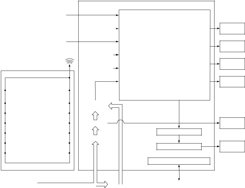
Indoor Unit Control Panel |
||||
|
|
|
|
|
|
|
|
|
|
Heat Exchanger Sensor |
|
|
|
|
|
|
|
|
|
|
|
|
|
|
|
|
|
|
|
|
|
|
|
|
|
|
Temperature Sensor |
|
|
|
|
|
|
|
|
|
|
|
|
|
|
||
|
|
|
|
|
|
|
|
|
|
|
|
|
|
|
|
|
|
|
Infrared Rays Signal Receiver |
|
|
|
|
|
|
|
|
|
|
|
|
|
|
|
|
|
Infrared |
|
|
|
|
|
||
|
Rays |
|
Initializing Circuit |
|
|
|||
CLOCK FREQUENCY 36,864kHz |
|
|
|
|
|
|||
|
Clock Frequency |
|
|
|||||
|
Remote Control |
|
|
|
||||
|
|
Oscillator Circuit |
|
|
||||
|
|
|
|
|
|
|
||
|
|
|
|
|
|
|
|
|
|
|
|
|
|
8MHz |
|||
|
Operation (START/STOP) |
|
|
|
||||
|
|
|
|
|
|
|
||
|
|
|
|
|
|
|
|
|
|
|
|
|
|
|
|
||
|
Operation Mode Selection |
|
|
|
|
|
|
|
|
AUTO, COOL, DRY, FAN ONLY |
|
|
|
|
|
|
|
|
|
|
|
|
|
|
|
|
|
|
|
|
|
|
|
|
|
|
Thermo. Setting |
|
|
|
Power Supply |
|
|
|
|
|
|
||||||
|
|
|
|
|
Circuit |
|
|
|
|
|
|
|
|
||||
|
Fan Speed Selection |
|
|
|
|
|
|
|
|
|
|
|
|
|
|
|
|
|
|
|
|
|
|
|
||
|
|
|
|
|
|
|
|
|
|
|
|
|
|
|
|
|
|
|
ON TIMER Setting |
|
|
|
Photo Triac |
|
||
|
|
|
||||||
|
|
|
|
|
|
|
|
|
|
|
|
|
|
|
|
|
|
|
OFF TIMER Setting |
|
|
|
|
|
|
|
|
|
|
|
|
|
|
||
|
|
|
|
|
Noise Filter |
|
||
|
|
|
|
|
||||
|
Louver AUTO Swing |
|
|
|
|
|
|
|
|
|
|
|
|
|
|
||
|
|
|
|
|
|
|
|
|
|
|
|
|
|
|
|
|
|
|
Louver Direction Setting |
|
|
|
|
|
|
|
|
|
|
|
|
|
|
||
|
|
|
|
|
|
|
|
|
|
|
|
|
|
|
|
|
|
|
ECONO. |
|
|
|
|
|
|
|
|
|
|
|
|
|
|
|
|
M.C.U
Functions
• Louver Control
•3-minute Delay at Restart for Compressor
•Motor Revolution Control
•Processing
(Temperature Processing)
• Timer
• Serial Signal Communication
Louver ON/OFF Signal
Louver Driver
Serial Signal Transmitter/Receiver
From Outdoor Unit |
|
|
Transformer |
|
Serial Signal Communication |
|
|
|
|
|
|
Operation
Display
Timer
Display
ECONO.
Sign Display
PRE DEF.
Sign Display
Indoor
Fan Motor
Louver
Motor
(outdoor unit)
Unit Indoor .1-6
DIAGRAM BLOCK CONTROL .6
TD |
|
|
C.P.U |
|
|
|
|
|
|
|
|
|
|
|
|
Discharge |
|
|
4-Way Valve |
|
Relay |
4-Way |
|
Temperature |
|
|
|
|
|||
|
|
ON/OFF Signal |
|
RY05 |
Valve |
|
|
Sensor |
|
|
|
|
|||
|
|
|
|
|
|
|
|
TE |
|
|
|
Relay |
|
|
|
|
|
|
Driver |
|
|
|
|
Heat |
|
|
Compressor |
|
Relay |
Magnetic |
|
Exchanger |
|
|
|
Compressor |
|||
|
|
ON/OFF Signal |
|
RY07 |
Switch |
||
Sensor |
|
|
|
|
|||
|
|
|
|
|
|
|
|
|
|
|
Outdoor Fan |
Photo |
Triac |
Outdoor |
|
|
|
|
ON/OFF Signal |
Coupler |
Fan Motor |
|
|
– 11 – |
|
|
|
|
|||
|
|
|
|
|
|
|
|
|
|
|
|
Initializing Circuit |
Power |
|
|
|
|
|
|
Supply |
|
||
|
|
|
|
|
|
|
|
|
|
• |
Compressor Control |
|
|
(for Indoor Unit) |
|
Serial Signal |
Serial Signal |
• |
4-Way Valve Control |
Clock frequency |
|
|
|
Transmitter/ |
• |
Outdoor Fan Control |
|
|
|||
Communication |
Oscillator Circuit |
|
|
||||
Receiver |
|
|
|||||
|
• |
Defrost Operation |
|
|
|
|
|
(Indoor Unit) |
|
|
6MHz |
|
|
||
|
• |
Serial Signal Communication |
|
|
|
||
|
|
|
|
|
|
||
|
|
|
|
Power Supply Circuit |
Transformer |
|
|
|
|
|
|
|
RAS-18YAH-E : AC220–240V, 50Hz |
|
|
|
|
|
|
|
RAS-18YAH-A : AC240V, 50Hz |
|
|
Unit Outdoor .2-6

7. OPERATION DESCRIPTION
7-1. FAN ONLY Operation
(MODE of the remote control : FAN ONLY)
(1)Fan speed setting
1)When the FAN is set to AUTO, the indoor fan motor operates as shown in Fig 7-1-1.
2)When the FAN is set to LOW, MED, or HIGH, the indoor fan motor operates with a constant in volume as listed in Table 7-1-1.
temp. |
28 |
|
|
|
|
Room |
27 |
HIGH |
|
||
|
|
|
|
26 |
MED |
|
LOW(+) |
|
|
25 |
|
|
|
|
|
24 |
LOW |
|
LOW |
|
|
|
|
|
|
|
Fig. 7-1-1 Auto setting of air volume Table 7-1-1 Manual setting of FAN SPEED
|
Indication of |
HIGH Air volume |
|
FAN SPEED |
(m3/h) |
|
|
|
|
LOW |
550 |
|
|
|
|
MED |
650 |
|
|
|
|
HIGH |
750 |
|
|
|
(2)Once the setting is made, the operation mode is memorized in the microcomputer so that the same operation can be effected thereafter
simply by pushing the START/STOP button.
7-2. COOL Operation
(MODE of the remote control : COOL)
(1)Compressor, 4-way valve, outdoor fan and operation display are controlled as shown in Fig. 7-2-1.
|
|
+1 |
ON |
|
|
ON |
|
– |
|
|
|
|
|
||
(Roomtemp. Settemp.) |
|
OFF ON OFF OFF ON |
|||||
|
|
|
|||||
Set |
|
0 |
|
|
|
|
|
temp. |
|
Compressor |
relayCommon |
valveway-4 |
fanOutdoor |
OPERATION display |
|
|
|
|
|
|
|
||
Fig. 7-2-1
(2)A cool operation is carried out when the indoor microcomputer sends the operation signal to the outdoor microcomputer.
1)When the FAN is set to AUTO, the indoor fan motor operates as shown in Fig 7-2-2.
2)When the FAN is set to LOW, MED, or HIGH, the indoor fan motor operates with a constant in volume as listed in Table 7-1-1.
|
|
FAN |
|
temp.) |
|
AUTO |
Manual |
|
|
||
– Set |
+1,5 |
HIGH |
|
MED (+) |
|
||
temp. |
+1,0 |
|
According |
|
|
MED |
to the set |
(Room |
+0,5 |
|
position |
+0 |
LOW (+) |
|
|
|
|
||
|
|
|
|
|
|
LOW |
|
Set  –0,5
–0,5
temp.
RY01 OFF
Fig. 7-2-2
(3)Once the setting is made, the operation mode is memorized in the microcomputer so that the same operation can be effected thereafter simply by pushing the START/STOP button.
7-2-1. Louver Control
(1)By pushing the SET button of the remote control during the operation, the louver can be set to the desired position.
And the louver position is stored in the microcomputer, the louvers will be set to the position automatically at the next operation.
(2)When the AUTO button is pushed, the louver vertically swings within range of 25deg.
– 12 –
 Loading...