


RAS-18GKHP-ES2
Table of contents
 Loading...
FILE NO. SVM-06020
SERVICE MANUAL
AIR CONDITIONER
SPLIT WALL TYPE
RAS-24GKHP-ES2 / RAS-24GAH-ES2
RAS-18GKHP-ES2 / RAS-18GAH-ES2
RAS-24GKP-ES2 / RAS-24GA-ES2
RAS-18GKP-ES2 / RAS-18GA-ES2
May, 2006
24 Class18 Class

CONTENTS
FILE NO. SVM-06020
1. SPECIFICATIONS
4-4 Indoor Unit (RAS-24GKP-ES2, RAS-18GKP-ES2)
2.
5-3 RAS-24GKP-ES2 / RAS-24GA-ES2
CONSTR
7-10 QUIET Mode
UCTION VIEWS
7.
2-1
OPERA
Indoor Unit
7-11 COMFORT SLEEP mode
2-2
TION DESCRIPTION
7-1
Outdoor Unit
Outline of Air Conditioner Control
(24 Class)
7-2 Description of Operation Circuit
7-3 Hi POWER Mode
7-4 High-Temperature Limit Control
7-5 Low-Temperature Limit Control
7-6 Defrosting Operation
7-7 A
2-3
uto Restar
t Function
Outdoor Unit
7-8
(18 Class)
Filter Check Lamp
7-9 Self-Cleaning function
3. WIRING DIAGRAM
3-1
3-2
RAS-24GKHP-ES2 / RAS-24GAH-ES2
3-3
RAS-18GKHP-ES2 / RAS-18GAH-ES2
RAS-24GKP-ES2 / RAS-24GA-ES2
4. SPECIFICATION OF ELECTRICAL PARTS
4-1 Indoor Unit (RAS-24GKHP-ES2, RAS-18GKHP-ES2)
4-2 Outdoor Unit (RAS-24GAH-ES2)
4-3 Outdoor Unit (RAS-18GAH-ES2)
4-5 Outdoor Unit (RAS-24GA-ES2)
4-5 Outdoor Unit (RAS-18GA-ES2)
5. REFRIGERATION CYCLE DIAGRAM
5-1
5-2
RAS-24GKHP-ES2 / RAS-24GAH-ES2
5-4
RAS-18GKHP-ES2 / RAS-18GAH-ES2
5-4
RAS-18GKP-ES2 / RAS-18GA-ES2
RAS-B18NKPX / RAS-18N2AX
6. CONTROL BLOCK DIAGRAM
6-1 RAS-24GKHP-ES2, RAS-18GKHP-ES2
6-2 RAS-24GKP-ES2, RAS-18GKP-ES2
3-3
RAS-18GKP-ES2 / RAS-18GA-ES2
- 1 -

- 2 -
• This air conditioner is charged with
HFC (R410A) that doesn't deplete the
Ozone layer.
• This air conditioner requires special
installation for the refrigerant R410A.
FILE NO. SVM-06020
8. INSTALLATION PROCEDURE
8-1 Safety Cautions
8-2 Installation Diagram of Indoor and Outdoor Units
8-3 Installation
8-4 Indoor Unit
8-5 Outdoor Unit
8-6 How to Set Remote Control Selector Switch
8-7 Others
9. TROUBLESHOOTING CHART
9-1 Troubleshooting Procedure
9-2 Basic Check Items
9-3 Primary Judgement
9-4 Self-Diagnosis by Remote Control (Check Code)
9-5 How to Diagnose Faulty Part
9-6 Troubleshooting for Indoor Unit
9-7 Troubleshooting for Wiring (Interconnect cable and Serial Signal
Wire)
9-8 Troubleshooting for P.C. Board
9-9 Troubleshooting for Remote Control
10. PARTS REPLACEMENT
10-1 Indoor Unit
10-2 Outdoor Unit (RAS-24GAH-ES2, RAS-24GA-ES2)
10-3 Outdoor Unit (RAS-18GAH-ES2, RAS-18GA-ES2)
11. EXPLODED VIEWS AND PARTS LIST
11-1 Indoor Unit (E - Parts Assy)
11-2 Indoor Unit
11-3 Outdoor Unit
11-4 Outdoor Unit (RAS-18GAH-ES2)
(RAS-24GAH-ES2)
11-5 Outdoor Unit (RAS-24GA-ES2)
11-6 Outdoor Unit (RAS-18GA-ES2)
MODEL
ITEM
Capacity
220V 240V 220V 240V 220V 240V 220V 240V 220V 240V 220V 240V
kW 6.30 6.30 6.80 6.90 6.80
6.85
5.00 5.05 5.45
5.55
5.30
5.35
Phase 1∅
Power source V 220 - 240
Hz
50
Power consumption W 2430 2510 2400 2480 2560 2690 1850 1900 1678 1748 1860 1960
Power factor % 98 85 99 88 99 92 98 97 94 92 97 96
220V 240V 220V 240V 220V 240V 220V 240V 220V 240V 220V 240V
Running current A 0.3/ 0.3/
0.3/
0.3/11.75 0.3/12.20
0.3/ 0.3/ 0.3/ 0.3/
0.3/8.4 0.3/8.2
Indoor/Outdoor 11.0
11.23
8.3 7.9 7.8 7.6
Starting current A
54
36
Moisture removal lit/h 2.5 2.7 2.0 2.0
Noise
Indoor (H/M/L) dB
45/43/41/39/37
44/42/39/37/35
Outdoor (220-240V) dB 56-57 57-58 56-57 52-53 53-54 51-52
Refrigerant
Name of refrigerant R410A
Rated amount
kg
1.70
1.15
1.26
Refrigerant control Capillary tube
Gas side size mm ∅12.7
Connection type Flare connection
Liquid side size mm ∅6.35
Interconnection Connection type Flare connection
pipe Maximum length
m
15*
1
(One way) 25*
2
20*
2
Maximum height
m 8
difference
INDOOR UNIT RAS-24GKHP-ES2 RAS-24GKP-ES2 RAS-18GKHP-ES2 RAS-18GKP-ES2
Height mm 298
Dimensions Width mm 998
Depth mm 220
Net weight kg 13
Evaporator type Finned tube
Indoor fan type Cross flow fan
High fan m
3
/h 900 900 900 900 900 900
Air volume Medium fan m
3
/h 750 800 750 667 708 667
Low fan m
3
/h 625 667 625 543 584 543
Fan motor output W 30
Air filter Honeycomb woven filter with PP frame
OUTDOOR UNIT RAS-24GAH-ES2 RAS-24GA-ES2 RAS-18GAH-ES2 RAS-18GA-ES2
Height mm
715
Dimensions Width mm 780 780 780
Depth mm 290
290
Net weight kg 56 52 44 39
Condenser type Finned tube
Outdoor fan type Propeller fan
Airflow volume m
3
/h 2400 2550 2400 2550 2400 2550 2350 2450 2350 2450 2120 2200
Fan motor output W 42 42
Compressor
Model
PA290X3CS-4MU1
PA225X2CS-4KU1
Output W 2160 1500
Safety device IOL, Td Sensor IOL IOL, Td Sensor IOL
Louver type Automatic louver
Usable outdoor temperature range °C 15 ~ 43 -10 ~ 24 21 ~ 43 15 ~ 43 -10 ~ 24 21 ~ 43
1. SPECIFICATIONS
RAS-24GKHP-ES2 RAS-24GKP-ES2 RAS-18GKHP-ES2 RAS-18GKP-ES2
RAS-24GAH-ES2 RAS-24GA-ES2 RAS-18GAH-ES2 RAS-18GA-ES2
Cooling Heating Cooling Cooling Heating Cooling
10
33
10.7
0.3/
11.45
54
1.90
550
290
Note *1 Chargeless pipe
*2 Maximum pipe
FILE NO. SVM-06020
550
- 3 -
Note : 1
· Capacity is based on the following temperature conditions.
Note : 2
· Charge refrigerant according to the table below.
Refrigerant
RAS-24GKHP-ES2 / RAS-24GAH-ES2
RAS-18GKHP-ES2 / RAS-18GAH-ES2
RAS-24GKP-ES2 / RAS-24GA-ES2 RAS-18GKP-ES2 / RAS-18GA-ES2
*1
No need to charge
15m or less
15m or less
extra refrigerant
*2 Need to charge
Over 15m up to 25m (20g/m) Over 15m up to 20m (20g/m)
extra refrigerant
Temperature
Condition
JIS B8615-1
Cooling Heating
Indoor unit inlet air temperature
(DB) 27°C 20°C
(WB) 19°C 15°C
Outdoor unit inlet air temperature
(DB) 35°C 7°C
(WB) 24°C 6°C
FILE NO. SVM-06020
- 4 -
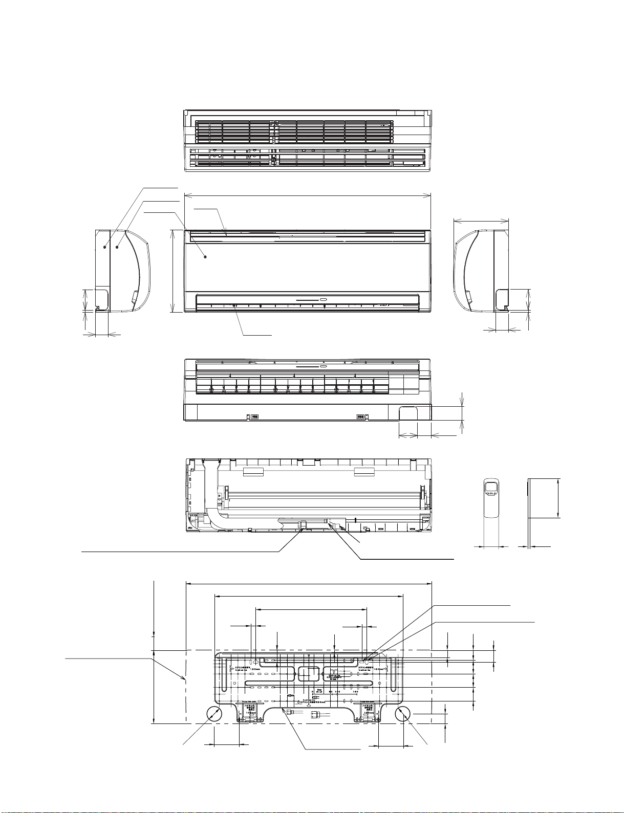
2. CONSTRUCTION VIEWS
2-1. Indoor Unit
FILE NO. SVM-06020
Air outlet
Air inlet
998
220
50
75
8
Knock out system
75
56
50
Back body
Front panel
Grille inlet
298
75
7
51
Knock out system
55 or more
Minimum distance
to ceiling
100
40
48
450
20
20
48
100
∅65
998
298
10
763.5
5555
55
41
29
57
18
160
∅6
5
Connection pipe (0.39 m)
(Flare ∅15.88)
Connection pipe (0.49 m)
Wireless remote control
(Flare ∅6.35)
(For stud bolt ∅6)
(For stud bolt ∅8 -∅10)
Drain hose (0.54 m)
Installation
Plate outline
Outline of indoor unit
- 5 -
HANDLE
COVER-PV
HANDLE
600
Z View
Service port
321
307
A Detail Drawing (Back leg)
Ø
25 Drain outlet
2
Ø
11x14 Hole
(For
Ø
8-
Ø
10 anchor bolt)
B
Ø
6
Hole
Ø
11x14 Hole
50
36
R
15
R
5.5
Ø
6 hole
28
321
86
A
124109
6
00 or more
Air out
let
321
600
Air inlet
4x
Ø
11 Long holes(For
Ø
8-
Ø
10 anchor bolt)
Gas-side
(Flare
Ø
15.88)
Liquid side
(Flare
Ø
6.35)
90 600 90 69
342
321
Z
50
36
R
15
B Detail Drawing (Front leg)
Ø
436
FAN-GUARD
715
290
275
600 or more
84
129
54
Electrical part cover
321
307
100 or more
100 or more
Installation dimension
2.2 Outdoor Unit (24 Class)
FILE NO. SVM-06020
- 6 -
321
307
Z View
600
A detail Drawing (Back leg)
321
307
Ø
25 Drain outlet
11 x 14
Hole
(For 8 -
10 anchor bolt)
B Detail Drawing (Front leg)
FAN-GUARD
COVER-PV
Electrical part cover
Liquid side
(Flare 6.35)
Ø
Ø
Gas side
(Flare 12.7)
Service port
4x 11 Long holes(For 8- 10 anchor bolt)
Installation dimension
Air outlel
100 or more
100 or more
600 or more
600 or more
Air intlel
Ø
Ø
Ø
Ø
6 hole
86
Ø
6 hole
Ø
11x14 hole
R
15
28
A
321
R5.5
36
109 124
50
129
84
5
4
600
321
9060090
275
290
550
Ø
436
Z
R
15
50
36
-
2
321
342
69
Ø
Ø
Ø
2.3 Outdoor Unit (18 Class)
FILE NO. SVM-06020
- 7 -

FILE NO. SVM-06020
3. WIRING DIAGRAM
3-1.
RAS-24GKHP-ES2 / RAS-24GAH-ES2
3
1
2
10
10
98
7
1 2 3 4 65 10
Infrared rays receive
5 64
CN13
321
7
8 9
9871 2 3
CN25
P04BLK
4 6
WHI
5
250V6.3A
F01
DSA
Varistor
motor
Louver
BLU
ORN
5
5 2
23
3
1
1
RED
YEL
CN07
PNK
4
4
98 1071 2 3
and Indication parts
4 65
YEL
GRY
BRW
TEMP FUSE
145 C
6
6
5
5
4
4
1
3
2
1
3
2
+5 VDC
+12 VDC
Serial Signal
circuit
MAIN P.C. BOARD
(WP-003)
CN23
CN31
CN30
BRW
6
6
BLU
BLU
BLU
BLU
BLU
BLU
BLU
BLU
BLU
WP-003
BRW : BROWN
RED : RED
WHI : WHITE
YEL : YELLOW
BLU : BLUE
BLK : BLACK
GRY : GRAY
ORN : ORANGE
GRN : GREEN
GRN&YEL : GREEN & YELLOW
COLOR IDENTIFICATION
PNK : PINK
DISCHARGE
PIPE
SENSOR (TD)
HEAT
EXCHANGER
SENSOR (TE)
CN08
CN07
BLU
BLU
BLK
BLK
1
1
2
3
3
1
1
2
3
3
i
L
N
3
1
2
i
FERRITE CORE
GRN&YEL
RED
RED
BLK
BLK
MAGNETIC
CONTACTOR
R
A1
A2
52C
U
S
V
T
W
PNK
WHI
COMPRESSOR TERMINAL
BLK
S
R
C
WHI
BLK BLK
COIL FOR
4 WAY VALVE
RED
RED
RED
CAPACITOR CAPACITOR
BLK
BLK
WHI
RED
CN01
CN05
GRY
1
3
5
7
9
1
3
5
7
9
GRN&YEL
CHASSIS
TRANSFORMER
BLK
BLK
RED
RED
1
1
3
3
1
1
3
3
2
CN11
BLU
YEL
1
3
1
3
1
1
3
CN02
BLU
BLU
11
33
CN03
F01
250VAC T6. 3A
CR11
CR12
CR13
RY07
RY05
RY06
SG01
CN06
TNR
R74
TNR
R73
MAIN P.C. BOARD (MCC-890)
COMPRESSOR
FAN MOTOR
POWER SUPPLY
220- 240 V ~ 50 Hz
OUTDOOR
TERMINAL
BLOCK
OUTDOOR
UNIT
R
S
C
- 8 -

FILE NO. SVM-06020
3-2. RAS-18GKHP-ES2 / RAS-18GAH-ES2
DISCHARGE
PIPE
SENSOR (TD)
HEA
T
EXCHANGER
SENSOR (TE)
CN08
CN07
BLU
BLU
BLK
BLK
1
1
2
3
3
1
1
2
3
3
3
1
2
i
L
N
3
1
2
i
FERRITE
CORE
GRN&YEL
RED
RED
BLK
BLK
MAGNETIC
CONTACTOR
R
A1
A2
52C
U
S
V
T
W
PNK
WHI
COMPRESSOR TERMINAL
BLK
S
R
C
WHI
BLK
BLK
COIL FOR
4 WAY VALVE
RED
RE
D
RED
CAPACITOR CAPACITOR
BLK
BLK
WHI
RED
CN01
CN05
GRY
1
3
5
7
9
1
3
5
7
9
GRN&YEL
CHASSIS
TRANSFORMER
BLK
BLK
RED
RED
1
1
3
3
1
1
3
3
2
CN11
BLU
YEL
1
3
1
3
1
1
3
CN02
BLU
BLU
11
33
CN03
F01
250VAC T6. 3A
CR11
CR12
CR13
RY07
RY05
RY06
SG01
CN06
TNR
R74
TNR
R73
MAIN P.C. BOARD (MCC-890)
POWER SUPPLY
220-240 V~ 50 Hz
INDOOR
TERMINAL
BLOCK
OUTDOOR
TERMINAL
BLOCK
INDOOR
UNIT
OUTDOOR
UNIT
COMPRESSOR
FAN MOTOR
10
10
98
7
1 2 3 4 65 10
Infrared rays receive
5 64
CN13
321
7
8 9
9871 2 3
CN25
P04BLK
4 6
WHI
5
250V6.3A
F01
DSA
Varistor
motor
Louver
BLU
ORN
5
5 2
23
3
1
1
RED
YEL
CN07
PNK
4
4
98 1071 2 3
and Indication parts
4 65
YEL
GRY
BRW
TEMP FUSE
145 C
6
6
5
5
4
4
1
3
2
1
3
2
+5 VDC
+12 VDC
Serial Signal
circuit
MAIN P.C. BOARD
(WP-003)
CN23
CN31
CN30
BRW
6
6
BLU
BLU
BLU
BLU
BLU
BLU
BLU
BLU
BLU
WP-003
BRW : BROWN
RED : RED
WHI : WHITE
YEL : YELLOW
BLU : BLUE
BLK : BLACK
GRY : GRAY
ORN : ORANGE
GRN : GREEN
GRN&YEL : GREEN & YELLOW
COLOR IDENTIFICATION
PNK : PINK
R
S
C
- 9 -
FILE NO. SVM-06020
3
1
2
L
N
3
1
2
GRN&YEL
RED
RED
RED
RED
BLK
BLK
CHASSIS
GRY
POWER SUPPLY
220 − 240 V ~ 50 Hz
SPARK KILLER
MAGNETIC CONTACTOR
BLK BLK
RED
A2 A1
52C
1/L1 2/T1
COMPRESSOR
WHI
PNK
BLK
C
S
R
CAPACITOR
CAPACITOR
WHI
RED
FAN MOTOR
BLK
COMPRESSOR TERMINAL
INDOOR
TERMINAL
BLOCK
OUTDOOR
TERMINAL
BLOCK
INDOOR
UNIT
OUTDOOR
UNIT
3/L2 4/T2
6/T35/L3
105 64321
7
8 9
5 98
7
1 2 3 4 6 10
YEL
GRY
BRW
TEMP FUSE
145 C
6
6
5
5
4
4
1
3
2
1
3
2
Control
Fan motor
circuit
Power supply
circuit
(TC)
sensor
Heat exchanger
(TA)
sensor
Thermo.
1
1
2
CN03
BLK
2
BLK
BLK
2
BLK
CN01
21
1
MAIN P.C. BOARD
(WP-003)
CN27
CN31
BRW
6
6
BLU
BLU
BLU
BLU
BLU
BLU
BLU
BLU
BLU
10
98
7
1 2 3 4 65 10
and Indication parts
5 64
CN13
321
7
8 9
CN25
P04
GRN&YEL
BLK
WHI
Varistor
250V
6.3A
F01
DSA
Varistor
motor
Louver
BLU
ORN
5
5 2
23
3
1
1
RED
YEL
CN07
PNK
4
4
Infrared rays receive
CN30
BRW : BROWN
RED : RED
WHI : WHITE
YEL : YELLOW
BLU : BLUE
BLK : BLACK
GRY : GRAY
ORN : ORANGE
GRN : GREEN
GRN&YEL : GREEN & YELLOW
COLOR IDENTIFICATION
PNK : PINK
R
S
C
3-3. RAS-24GKP-ES2 / RAS-24GA-ES2
- 10 -
FILE NO. SVM-06020
3
1
2
L
N
3
1
2
GRN&YEL
RED
RED
GRY
RED
BLK
BLK
BLK
BLK
GRN&YEL
CHASSIS
POWER SUPPLY
220 − 240 V ~ 50 Hz
MAGNETIC
CONTACTOR
A1
A2
U
V
W
R
S
T
SPARK KILLER
FAN MOTOR
WHI
BLK
RED
RED
CAPACITOR
WHI
BLK
PNK
S
R
C
CAPACITOR
COMPRESSOR
RED
INDOOR
TERMINAL
BLOCK
OUTDOOR
TERMINAL
BLOCK
INDOOR
UNIT
OUTDOOR
UNIT
COMPRESSOR TERMINAL
(or A)
(or B)
105 64321
7
8 9
5 98
7
1 2 3 4 6 10
YEL
GRY
BRW
TEMP FUSE
145 C
6
6
5
5
4
4
1
3
2
1
3
2
Control
Fan motor
circuit
Power supply
circuit
(TC)
sensor
Heat exchanger
(TA)
sensor
Thermo.
1
1
2
CN03
BLK
2
BLK
BLK
2
BLK
CN01
21
1
MAIN P.C. BOARD
(WP-003)
CN27
CN31
BRW
6
6
BLU
BLU
BLU
BLU
BLU
BLU
BLU
BLU
BLU
10
98
7
1 2 3 4 65 10
and Indication parts
5 64
CN13
321
7
8 9
CN25
P04
GRN&YEL
BLK
WHI
Varistor
250V
6.3A
F01
DSA
Varistor
motor
Louver
BLU
ORN
5
5 2
23
3
1
1
RED
YEL
CN07
PNK
4
4
Infrared rays receive
CN30
BRW : BROWN
RED : RED
WHI : WHITE
YEL : YELLOW
BLU : BLUE
BLK : BLACK
GRY : GRAY
ORN : ORANGE
GRN : GREEN
GRN&YEL : GREEN & YELLOW
COLOR IDENTIFICATION
PNK : PINK
R
S
C
3-4. RAS-18GKP-ES2 / RAS-184GA-ES2
- 11 -
FILE NO. SVM-06020
4. SPECIFICATION OF ELECTRICAL PARTS
4-1. Indoor Unit (RAS-24GKHP-ES2, RAS-18GKHP-ES2)
4-2. Outdoor Unit (RAS-24GAH-ES2)
No. Parts name Type Specifications
Output (Rated) 2200W, 2poles, 1 phase, 220 − 240V, 50Hz
1 Compressor PA290X3CS-4MU1 Winding resistance (Ω) Red-Black White-Black
(at 20°C) 1.13 2.10
Output (Rated) 42W, 4poles, 1 phase, 220 – 240V, 50Hz
2 Fan motor (for outdoor) FG-240-42A-1 Winding resistance (Ω) Red-Black White-Black
(at 20°C) 128 126
3
Running capacitor
451305L AC 450V, 3.0µF
(for fan motor)
4
Running capacitor
RS44B506U0218S AC 440V, 50µF
(for compressor)
5
Solenoid coil
VHV (STF) AC 220 ~ 240V
(for 4-way valve)
6 Thermo sensor TE / TD 10kΩ at 25°C / 50kΩ at 25°C
7 Magnetic contactor CLK-35J 220 ~ 240V, 50Hz
8 Transformer TT-05 220 ~ 240V
9 Microcontroller TMP47C840N
10 Varistor (R73, R74) 15G471K 470V
11 Fuse (F01) TSCR T6.3A, 250V
No. Parts name Type Specifications
1 Fan motor (for indoor) AFS-220-31-4A AC 200 − 240V, 31W
2 Thermo sensor (TA-sensor) ——— 10 kΩ at 25°C
3 Micro Power Module (M01) µRM1260V DC 390 V, Secondary DC 12 V
4 Microcontroller TMP87CM40AN
5 Heat exchanger sensor
——— 10 kΩ at 25°C
(TC-sensor)
6 Line filter (L01) LC*SS11V-06270 27mH, 600mA
7 Diode (DB01) D3SBA60 4 A, 600 V
8 Capacitor (C63) EKMH401VSN470MP20S 4.7µF, 400 V
9 Fuse (F01) BET6.3A T6.3 A, 250 V
10 Varistor (R21, R22) TND15G561K 560 V
11 Resistor (R319) RF-2TK5R6 5.6Ω , 2 W
12 Louver motor 35BYJ46 Output (Rated) 2 W, 10 poles, 1 phase,
DC 12 V
- 12 -
FILE NO. SVM-06020
4-3. Outdoor Unit (RAS-18GAH-ES2)
Output (Rated) 1500W, 2poles, 1 phase, 220 − 240V, 50Hz
1 Compressor PA225X2CS-4KU1 Winding resistance (Ω) Red-Black White-Black
(at 20°C) 1.54 2.48
Output (Rated) 42W, 4poles, 1 phase, 220 – 240V, 50Hz
2 Fan motor (for outdoor) FG-240-42A-1 Winding resistance (Ω) Red-Black White-Black
(at 20°C) 128 126
3
Running capacitor
451305L AC 450V, 3.0 µF
(for fan motor)
4
Running capacitor
RS44B506U0218S AC 440V, 50µF
(for compressor)
5
Solenoid coil
VHV (STF) AC 220 − 240V
(for 4-way valve)
6 Thermo sensor TE / TD 10kΩ at 25°C / 50kΩ at 25°C
7 Magnetic contactor CLK-26J 220 − 240V, 50Hz
8 Transformer TT-05 220 − 240V
9 Microcomputer TMP47C840N
No. Parts name Type Specifications
10 Varistor (R73, R74) 15G471K 470V
11 Fuse (F01) TSCR T6.3A, 250V
4-4. Indoor Unit (RAS-24GKP-ES2, RAS-18GKP-ES2)
No. Parts name Type Specifications
1 Fan motor (for indoor) AFS-220-31-4A AC 200 − 240V, 31W
2 Thermo sensor (TA-sensor) ——— 10 kΩ at 25°C
3 Micro Power Module (M01) µRM1260V DC 390 V, Secondary DC 12 V
4 Microcontroller TMP87CM40AN
5 Heat exchanger sensor
——— 10 kΩ at 25°C
(TC-sensor)
6 Line filter (L01) LC*SS11V-06270 27mH, 600mA
7 Diode (DB01) D3SBA60 4 A, 600 V
8 Capacitor (C63) KMH400VSSN47M22S 4.7µF, 400 V
9 Fuse (F01) BET6.3A T6.3 A, 250 V
10 Varistor (R21, R22) TND15G561K 560 V
11 Resistor (R319) RF-2TK5R6 5.6Ω, 2 W
12 Louver motor
35BYJ46 Output (Rated) 2 W, 10 poles, 1 phase,
DC 12 V
13 Relay : (RY04) G5NB-1A Coil DC 12V, 16.7mA, Contact AC 250V, 1A
- 13 -
FILE NO. SVM-06020
4-5. Outdoor Unit (RAS-24GA-ES2)
No. Parts name Type Specifications
Output (Rated) 2200W, 2poles, 1 phase, 220 − 240V, 50Hz
1 Compressor PA290X3CS-4MU1 Winding resistance (Ω ) Red-Black White-Black
(at 20°C) 1.13 2.10
Output (Rated) 42W, 4poles, 1 phase, 220 − 240V, 50Hz
2 Fan motor (for outdoor) FG-240-42A Winding resistance (Ω) Red-Black White-Black
(at 20° C) 128 126
3
Running capacitor
451305L AC 450V, 3.0µ F
(for fan motor)
4
Running capacitor
RS44B506U0218S
AC 440V, 50µ F
(for compressor)
5
Magnetic contactor
CLK-35J
220 − 240V, 50Hz
4-6. Outdoor Unit (RAS-18GA-ES2)
No. Parts name Type Specifications
Output (Rated) 1500W, 2poles, 1 phase, 220 − 240V, 50Hz
1 Compressor PA225X2CS-4KU1 Winding resistance (Ω) Red-Black White-Black
(at 20°C ) 1.54 2.48
Output (Rated) 42W, 6poles, 1 phase, 220 − 240V, 50Hz
2 Fan motor (for outdoor) WLF-240-42A-1 Winding resistance (Ω) Red-Black White-Black
(at 20°C) 188 289
3
Running capacitor
451205L AC 450V, 2.0µF
(for fan motor)
4
Running capacitor
RS44B506U0218S AC 440V, 50µF
(for compressor)
5
Magnetic contactor
CLK-26J
220 − 240V, 50Hz
- 14 -
FILE NO. SVM-06020
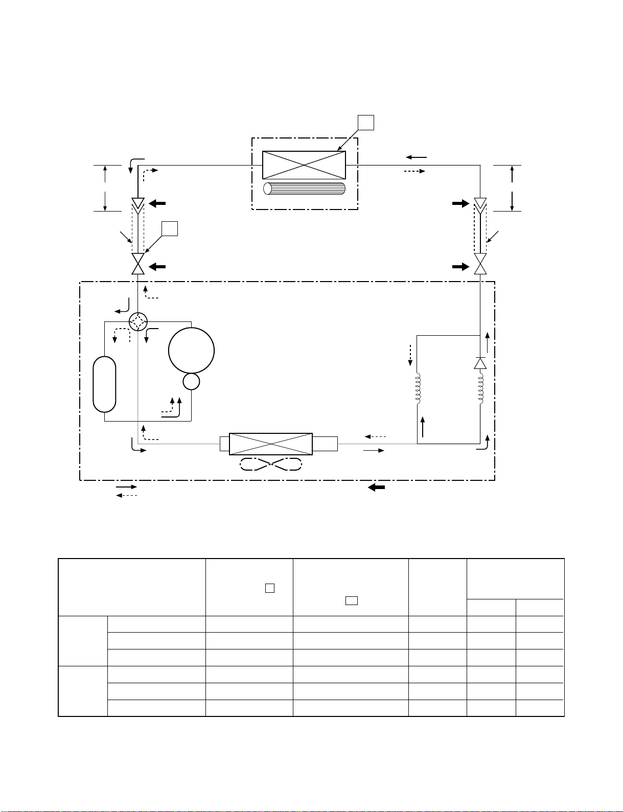
5. REFRIGERATION CYCLE DIAGRAM
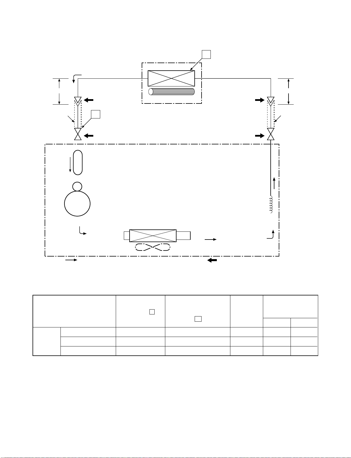
5-1. RAS-24GKHP-ES2 / RAS-24GAH-ES2
Note :
• Measure the heat exchanger temperature at the center of U-bend. (By means of TC sensor)
*1 • During heating overload operation, a value for the high temperature limit control operation is included.
Ambient temp.
conditions DB/WB
(°C)
Indoor Outdoor
Standard 3.0 48.2 High 20/– 7/6
Heating Overload*1 3.93 56.4 Low 27/– 24/18
Low temperature 2.17 38.4 High 20/– –10/–10
Standard 3.03 8.7 High 27/19 35/24
Cooling Overload 4.02 12.1 High 32/23 43/26
Low temperature 2.1 0.3 Low 21/15 21/15
Standard
pressure
P
(MPaG)
Surface temp. of heat
exchanger interchanging
pipe
T1
(°C)
Fan speed
(indoor)
50Hz
Heat exchanger
Indoor unit
Cross flow fan
Cooling
Heating
4-way valve
Heating
Cooling
Compressor
Condenser
Propeller fan
Outdoor unit
PA290X3CS-4MU1
Cooling
Heating
Mark(
)means check points of Gas Leak.
O.D.:12.7mm
O.D.:6.35mm
Cooling
Heating
Packed valve
Gas container connection (Reinstall etc.)
(∅
12.7)
Packed valve
(∅
6.35)
0.
3
9m
(Connecting pipe)
∅
12.7
0.
49m
(Connecting pipe)
∅
6.35
T1
P
Refrigerant
R410A 1.
90 kg
Tank
Main
∅
2.0x1500
s
- 15 -

FILE NO. SVM-06020
5-2. RAS-18GKHP-ES2 / RAS-18GAH-ES2
Note :
• Measure the heat exchanger temperature at the center of U-bend. (By means of TC sensor)
*1 • During heating overload operation, a value for the high temperature limit control operation is included.
Ambient temp.
conditions DB/WB
(°C)
Indoor Outdoor
Standard 2.6 44.7 High 20/– 7/6
Heating Overload*1 3.0 ~ 3.6 49.0 ~ 56.0 Low 27/– 24/18
Low temperature 2.0 32.0 High 20/––10/–10
Standard 0.9 9.5 High 27/19 35/24
Cooling Overload 1.1 12.6 High 32/23 43/26
Low temperature 0.7 2.4 Low 21/15 21/15
Fan speed
(indoor)
50Hz
Standard
pressure
P
(MPaG)
Surface temp. of heat
exchanger interchanging
pipe
T1
(°C)
Indoor unit
Cross flow fan
Cooling
Heating
4-way valve
Heating
Cooling
Compressor
Condenser
Propeller fan
Outdoor unit
PA225X2CS-4KU1
Cooling
Heating
Mark(
)means check points of Gas Leak.
O.D.:12.7mm
O.D.:6.35mm
Cooling
Heating
Packed valve
(
∅
12.7)
Packed valve
(
∅
6.35)
0.39m
(Connecting pipe)
∅
12.7
0.49m
(Connecting pipe)
∅
6.35
T1
P
Refrigerant
R410A 1.
15 kg
Accumulator
Evaporator
Capillary tube
∅
2.0x1200
s
- 16 -
FILE NO. SVM-06020
5-3. RAS-24GKP-ES2 / RAS-24GA-ES2
Note :
• Measure the heat exchanger temperature at the center of U-bend. (By means of TC sensor)
Ambient temp.
conditions DB/WB
(° C)
Indoor Outdoor
Standard 3.183 7.0 High 27/19 35/24
Cooling Overload 4.040 11.7 High 32/23 43/26
Low temperature 1.651 -0.4 Low 21/15 21/15
Fan speed
(indoor)
50Hz
Standard
pressure
P
(MPaG)
Surface temp. of heat
exchanger interchanging
pipe
T1
(° C)
Heat exchanger
Indoor unit
Cross flow fan
Compressor
Condenser
Propeller fan
Outdoor unit
PA290X3CS-4MU1
Cooling
Mark(
)means check points of Gas Leak.
O.D.:12.7mm
O.D.:6.35mm
Cooling
Packed valve
Gas container connection (Reinstall etc.)
(∅
12.7)
Packed valve
(
∅
6.35)
0.39m
(Connecting pipe)
∅
12.7
0.49m
(Connecting pipe)
∅
6.35
T1
P
Refrigerant
R410A 1.70kg
Capillary tube
∅
2.0x900
s
Cooling
Accumulator
- 17 -

FILE NO. SVM-06020
5-4. RAS-18GKP-ES2 / RAS-18GA-ES2
Note :
• Measure the heat exchanger temperature at the center of U-bend. (By means of TC sensor)
Ambient temp.
conditions DB/WB
(°C)
Indoor Outdoor
Standard 1.1 10.0 High 27/19 35/24
Cooling Overload 1.2 13.0 High 32/23 43/26
Low temperature 0.6 2.0 Low 21/15 21/15
Fan speed
(indoor)
50Hz
Standard
pressure
P
(MPaG)
Surface temp. of heat
exchanger interchanging
pipe
T1
(°C)
Indoor unit
Cross flow fan
Cooling
Compressor
Condenser
Propeller fan
Outdoor unit
PA225X2CS-4KU1
Cooling
Mark(
)means check points of Gas Leak.
O.D.:12.7mm
O.D.:6.35mm
Cooling
Packed valve
(
∅
12.7)
Packed valve
(
∅
6.35)
0.39m
(Connecting pipe)
∅
12.7
0.49m
(Connecting pipe)
∅
6.35
T1
P
Refrigerant
R410A 1.
26 kg
Evaporator
Capillary tube
∅
1.7x400
s
- 18 -

FILE NO. SVM-06020
6. CONTROL BLOCK DIAGRAM
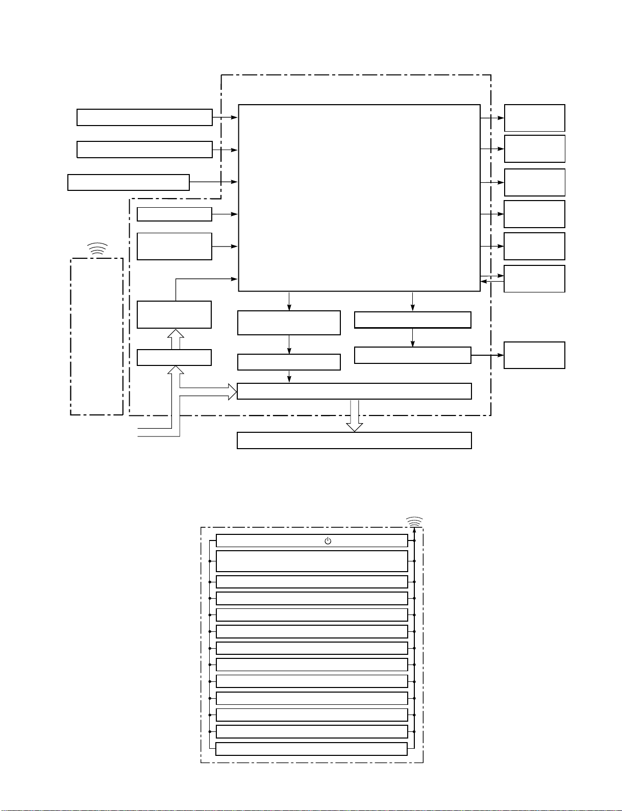
6-1. RAS-24GKHP-ES2, RAS-18GKHP-ES2
REMOTE CONTROL
Indoor Unit Control Panel
Heat Exchanger Sensor
Temperature Sensor
Infrared Rays Signal Receiver
Initiallizing Circuit
Clock Frequency
Oscillator Circuit
Power Supply
Circuit
Noise Filter
From Outdoor Unit
220 ~ 240 V AC 50 Hz
M.C.U.
Functions
• Louver Control
• 3-minute Delay at Restart for Compressor
• Motor Revolution Control
• Processing
• Timer
• Serial Signal Communication
Louver ON/OFF Signal
Louver Driver
Serial Signal Transmitter/Receiver
Serial Signal Communication
Operation
Display
Timer
Display
Filter Sign
Display
PRE DEF.
Sign Display
Indoor
Fan Motor
Hi Power
Sign Display
Louver Motor
Infrared
Rays
Remote
Control
(Temperature Processing)
Operation ( )Operation ( )
Remote Control
Operation Mode Selection
AUTO, COOL, DRY, HEAT, FAN ONLY
Temperature Setting
Fan Speed Selection
ON TIMER Setting
OFF TIMER Setting
Louver Auto Swing
Louver Direction Setting
ECO
Hi power
TIMER 1.3.5.9H
Infrared Rays
COMFORT SLEEP
QUIET
- 19 -
FILE NO. SVM-06020
6-2. RAS-24GKP-ES2, RAS-18GKP-ES2
Heat Exchanger Sensor
Relay RY04
Outdoor Unit
Outdoor unit
ON/OFF Signal
Relay Driver
Indoor Unit Control Panel
Temperature Sensor
Infrared Rays Signal Receiver
Initiallizing Circuit
Clock Frequency
Oscillator Circuit
Power Supply
Circuit
Noise Filter
From Outdoor Unit
220 ~ 240V AC 50Hz
M.C.U.
Functions
Louver Control
3-minute Delay at Restart for Compressor
Motor Revolution Control
Processing
Timer
Louver ON/OFF Signal
Louver Driver
Operation
Display
Timer
Display
Filter Sign
Display
Fan Only
Sign Display
Indoor
Fan Motor
Hi Power
Sign Display
Louver Motor
Infrared
Rays
Remote
Control
(Temperature Processing)
REMOTE CONTROL
Operation ( )Operation ( )
Remote Control
Operation Mode Selection
AUTO, COOL, DRY, FAN ONLY
Temperature Setting
Fan Speed Selection
ON TIMER Setting
OFF TIMER Setting
Louver Auto Swing
Louver Direction Setting
ECO
Hi power
TIMER 1.3.5.9H
Infrared Rays
COMFORT SLEEP
QUIET
- 36 -
FILE NO. SVM-06020
7. OPERATION DESCRIPTION
7-1-1. Louver contr
ol
(1) Vertical air flow louver
Position of veritcal air flow louver is automatically
controlled according to the operation mode.
Besides, position of vertical air flow louver can be
arbitrarily set by pressing [FIX] button.
The louver position which is set by [FIX] button is
stored in the microcomputer, and the louver is
automatically set at the stored position for the next
operation.
(2) Swing
If [SWING] button is pressed when the indoor unit
is in operation, the vertical air flow louver starts
swinging. When [FIX] button is pressed, it stops
swinging.
7-1-2. Indoor fan control (AC Fan motor)
(1) The indoor fan is operated by the stepless speed
change AC motor
.
(2) For air flow level, speed of the indoor fan motor is
controlled in five steps (LOW, LOW
+
, MED, MED
+
and HIGH). If AUTO mode is selected, the fan
motor speed is automatically controlled by the
difference between the preset temperature and
the room temperature.
7-1.Outline of Air Conditioner Control
This is a fixed capacity type air conditioner, which uses
a AC motor for an indoor fan. The AC motor drive
circuit is mounted in the indoor unit. And electrical
parts which operate the compressor and the outdoor
fan motor, are mounted in the outdoor unit.
The air conditioner is mainly controlled by the indoor
unit controller. The controller operates the indoor fan
motor based upon commands transmitted by the
remote control and transfers the operation commands
to the outdoor unit controller.
The outdoor unit controller receives operation
commands from the indoor unit, and operates the
outdoor fan motor and the compressor.
(1) Role of indoor unit controller
The indoor unit controller receives the operation
commands from the remote control and executes
them.
· Temperature measurement at the air inlet of the
indoor heat exchanger by the indoor
temperature sensor
· Temperature setting of the indoor heat
exchanger by the heat exchanger sensor
· Louver motor control
· Indoor fan motor operation control
· LED display control
· T ransferring of operation commands to the
outdoor unit
· Receiving of information of the operation status
and judging of the information or indication of
error
(2) Role of outdoor unit controller
The outdoor unit controller receives the operation
commands from the indoor controller and
executes them.
· Compressor operation
control
· Operation control of
outdoor fan motorf
·
when the outdoor unit receives the shutdown
command
· Defrost control in heating operation
(Temperature measurement by the outdoor heat
exchanger and control for the four-way valve
and the outdoor fan motor) *Heat pump Model
only
Turning off the compressor and outdoor fan
Operations according
to the commands
from the indoor unit
Cooling
OPERATION
Fan Only
Dry
MODE
1300
RAS-24GKHP Series
Model
RAS-18GKH Series
FAN TAP
RAS-24GKP Series
RAS-18GKP Series
Heat
rpm
Air Flow volume(m /h)
3
rpm
Air Flow volume(m /h)
3
rpm
Air Flow volume(m /h)
3
rpm
Air Flow volume(m /h)
3
UH H
M+
M L+
L L- UL SUL/SL-
SUL/SL-
UL
L-LL+
MUH H
H M+ M
L+
L L-
UL SUL
M+ M
900
900
13001300
900
1300
900
1300
900
1250 1200
1150 1050 1000 900 800 700
600
380
300
L+
L L-
600
500
300
220
700
380
600
300
461
700
380
800
461
700
380
543
800
461
900
543
800
461
625
900
543
1000
625
900
543
667
950
584
1050
667
950
584
750
1050
667
1150
750
1050
667
790
1150
750
1250
830
1150
750
830
Note : Under some function of setting. The fan motor is controlled automatically.
Then LOW
+
= LOW + MED and MED
+
= MED + HIGH
2
Table 7-1-1
2
−
−
−
−
−
−
−
−
−
−
−
−
−
−
−
−
1100
708
- 20 -
FILE NO. SVM-06020
7-2. Description of Operation Circuit
(1) When turning on the breaker, the operation lamp
blinks. This means that the power is on (or the
power supply is cut off.)
(2) When pressing [ ] button on the
remote control, receiving beep sounds from the
indoor unit, and the next operation is performed
together with opening the vertical air flow louver.
(3) Once the operation mode is set, it is memorized in
the microcomputer so that the previous operation
can be effected thereafter simply by pressing
[ ] button.
7-2-1. Fan only operation
([MODE] button on the remote control is set
to the fan only operation.)
(1) When [FAN] button is set to AUTO, the indoor fan
motor operates as shown in Fig. 7-2-1. When
[FAN] button is set to LOW, LOW
+
, MED, MED
+
or
HIGH, the motor operates with a constant air flow.
NOTE :
*1: The values marked with *1 are calculated and
controlled by the difference in motor speed
between M+ and L-.
Fig. 7-2-1 Setting of air flow [FAN:AUTO]
(2)
The Hi Power, ECO and COMFORT SLEEP
operation cannot be set.
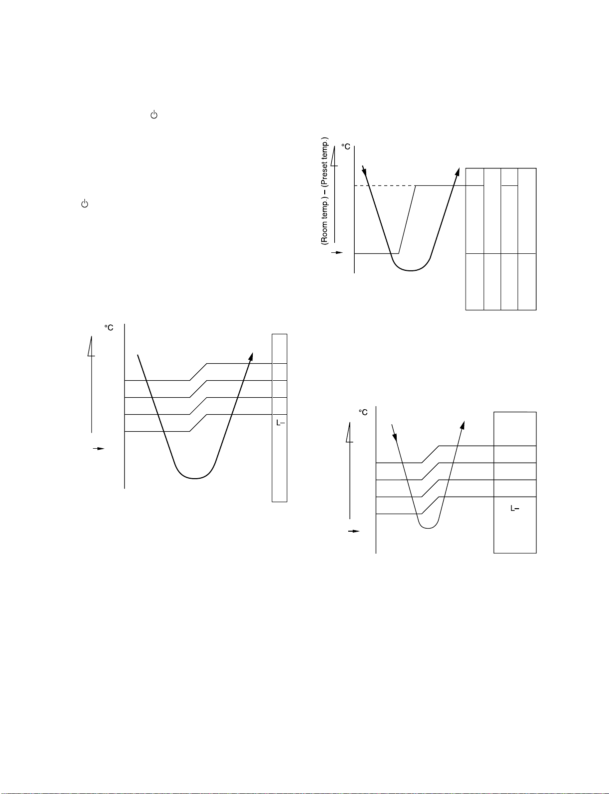
7-2-2. Cooling operation
([MODE] button on the remote control is set
to the cooling operation.)
(1) The compressor, 4-way valve, outdoor fan and
operation display lamp are controlled as shown in
Fig. 7-2-2.
Fig. 7-2-2
(2) When [FAN] button is set to AUTO, the indoor fan
motor operates as shown in Fig. 7-2-3. When
[FAN] button is set to LOW, LOW
+
, MED, MED
+
or
HIGH, the motor operates with a constant air flow.
NOTE :
*1: The values marked with *1 are calculated and
controlled by the difference in motor speed
between M+ and L-.
Fig. 7-2-3 Setting of air flow [FAN:AUTO]
(Preset temp.: 24°C)
+2
+2.5
+3
+1.5
+1
+0.5
0
M+
*1
*1
*1
(Room temp.)
-
(Preset temp.)
Preset
temp.
*1
*1
*1
+3
+2.5
+2
+1.5
+1
+0.5
-0.5
0
M+
(Room temp.)
-
(Preset temp.)
Preset
temp.
0.5
0
Preset
temp.
ON
ON
OFF OFF OFF ON
Compressor
4-way valve
Outdoor fan
OPERATION
display lamp
(Heat pump model)
- 21 -
FILE NO. SVM-06020
7-2-4. Heating operation *Heat pump model only
([MODE] button on the remote control is set
to the heating operation.)
(1) The compressor, 4-way valve, outdoor fan and
operation display lamp are controlled as shown in
Fig. 7-2-6.
Fig. 7-2-6
(2) When [FAN] button is set to AUTO, the indoor fan
motor operates as shown in Fig. 7-2-7. When
[FAN] button is set to LOW, LOW
+
, MED, MED
+
or
HIGH, the motor operates with a constant air flow.
*1, *2 : The values marked with *1 and *2 are
calculated and controlled by the difference in
motor speed between M+ and L.
Fig. 7-2-7 Setting of air flo w [FAN:AUTO]
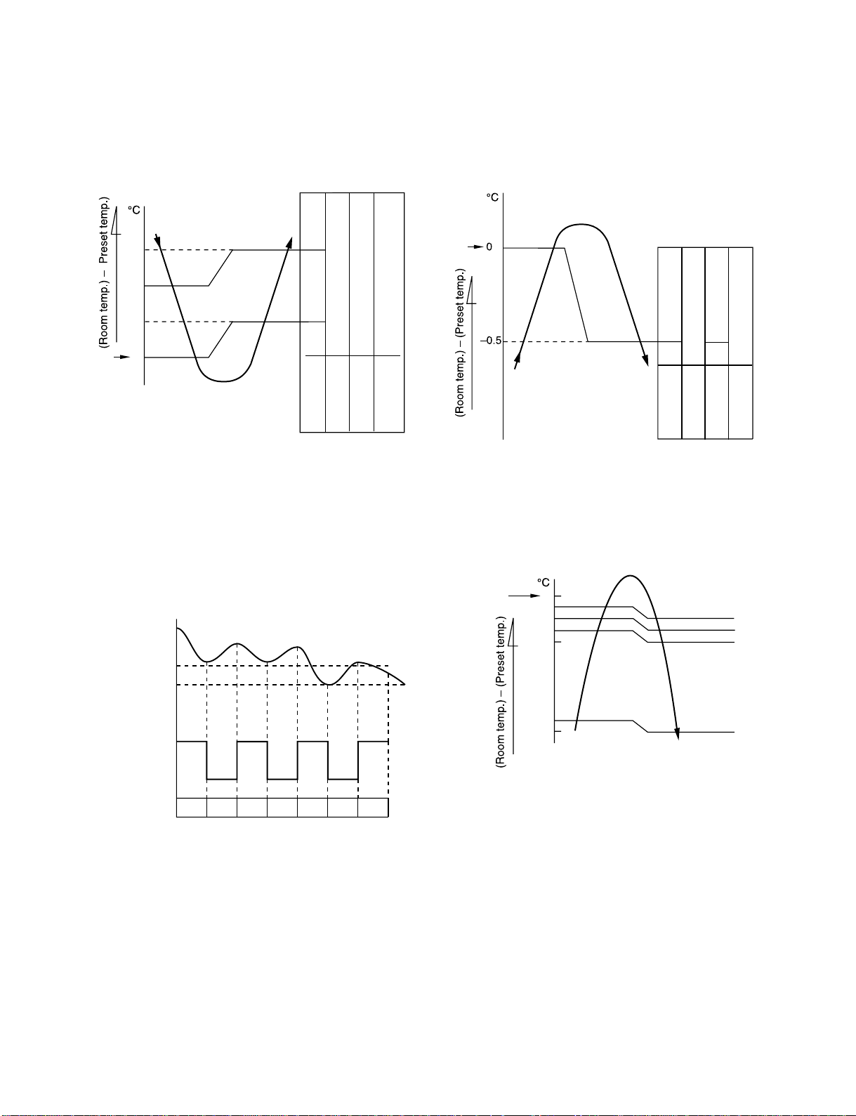
7-2-3. Dry operation
([MODE] button on the remote control is set
to the dry operation.)
(1) The compressor, 4-way valve, outdoor fan and
operation display lamp are controlled as shown in
Fig. 7-2-4.
Fig. 7-2-4
(2) The microprocessor turns the compressor on and
off at the regular intervals (4 to 6 minutes). While
the compressor is turning off, the indoor fan motor
operates in the SUPER LOW position.
The pattern of operation depending on the relation
between room temperature and preset
temperatures is shown in Fig. 7-2-5.
Fig. 7-2-5
(3) [FAN] button on the remote control is set to AUTO
only.
(4) The ECO and Hi Power operations can not be set.
Preset
temp.
OFF
ON
+3
+2
+1
0
OFF
4-way valve
Outdoor fan
OPERATION
Compressor
ON:6min.
OFF:4min.
ON:5min.
OFF:5min.
OFF
ON:6min.
OFF:4min.
ON:5min.
OFF:5min.
display lamp
Room temp.
Preset temp.+1
Preset temp.
Compressor
Outdoor fan
Indoor fan
L. *S.L. S.L.L. L. S.L. L.
ON ON ON ON
OFF OFF OFF
*Super Low
ON
OFF
ON
OFF
ON
ON
4-way valve
Outdoor fan
Compressor
Preset
temp.
OPERATION
display lamp
[FAN AUTO]
-0.5
-1
-1.5
-2
*1
*2
-5.0
-5.5
0
Preset
temp.
M
+
H
L
- 22 -
Loading...