


Modular Multi VRF System
Applications Manual
MMS-04AE-07-03
|
Contents |
Page |
Chapter |
|
|
|
|
|
|
|
General Information |
5 |
|
1 |
|
|
|
|
|
|
|
|
|
|
|
Indoor Units – General |
15 |
|
2 |
|
|
|
|
|
|
|
|
|
|
|
4-Way Cassette |
19 |
|
3 |
|
|
|
|
|
|
|
|
|
|
|
2-Way Cassette |
29 |
|
4 |
|
|
|
|
|
|
|
|
|
|
|
Duct |
33 |
|
5 |
|
|
|
|
|
|
|
|
|
|
|
Slim Duct |
37 |
|
6 |
|
|
|
|
|
|
|
|
|
|
|
Ceiling |
41 |
|
7 |
|
|
|
|
|
|
|
|
|
|
|
High Wall |
45 |
|
8 |
|
|
|
|
|
|
|
|
|
|
|
Chassis |
49 |
|
9 |
|
|
|
|
|
|
|
|
|
|
|
Low Wall |
53 |
|
10 |
|
|
|
|
|
|
|
|
|
|
|
Capacity Correction |
57 |
|
11 |
|
|
|
|
|
|
|
|
|
|
|
Outdoor Units |
71 |
|
12 |
|
|
|
|
|
|
|
|
|
|
|
Piping Design |
85 |
|
13 |
|
|
|
|
|
|
|
|
|
|
|
Controls |
98 |
|
14 |
|
|
|
|
|
|
|
|
|
|
|
Electrical Wiring |
113 |
|
15 |
|
|
|
|
|
|
|
|
|
|
|
Selection Example |
120 |
|
16 |
|
|
|
|
|
|
|
|
|
|
|
Commissioning Procedure |
132 |
|
17 |
|
|
|
|
|

4
General Information
Introduction |
1 |
|
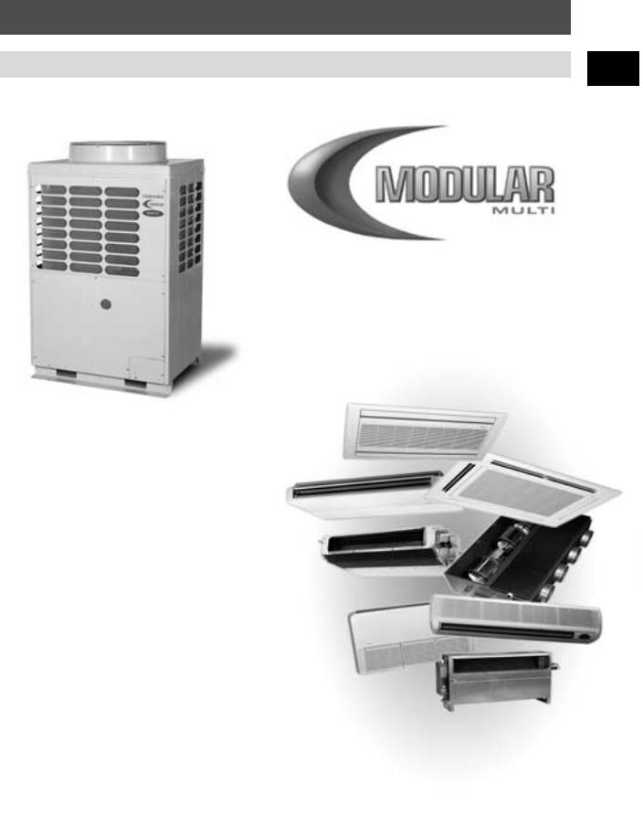
With the new Modular Multi System (MMS), Toshiba once again demonstrate that we are in touch with tomorrow. The design team looked to the future to develop a highly efficient, environmentally friendly system, with state of the art controls.
Linking the precision performance of their leading inverter technology with the functionality of fixed speed units,Toshiba have created a range of systems from 22.4 to 128.8 kW (8 to 46 hp). The inverter unit adjusts performance to match the desired output as each fixed speed unit operates as needed.
Modular Multi 2 pipe, heat pump and cooling only systems provide an economical solution to many of your heating and cooling needs and when combined with the Super Multi 3 pipe system, Toshiba covers the full spectrum of VRF applications.
5
General Information
Benefits of VRF
The Variable Refrigerant Flow (VRF) product segment is one of the fastest growing areas of the air conditioning industry due to the inherent flexibility of the system.
Specifiers are selecting this type of air conditioning product because it provides the economy and stability of a network system with the versatility of an independent system.
The system is ideal for variable load situations such as hotels, offices and shops.
VRF systems are compact and discreet which makes them ideal for applications when the air conditioning system is being retro-fitted to the existing building.
Since the air is conditioned locally there is no need for large ductwork throughout the building for the flow of heated/cooled air. Only small pipes are necessary to carry the refrigerant to the desired location. Because the air is cooled to the desired temperature at the point of use, the end user gets rapid, precise temperature control.
When integrated with control systems the performance can be optimised to achieve ultra low energy consumption, particularly when there is high diversity in the capacity demand.
Qualifies for enhanced
Capital Allowance
As a variable-speed drive system this product is on DEFRA’s Energy Technology Product list and entities the purchaser in the UK to a tax benefit under the ECA scheme, Further details are on the following website: www.eca.gov.uk
6

General Information |
|
|
|
|
|
|
|
|
|
|
|
|
|
|
Benefits of the Modular Multi System |
|
|
1 |
|
|
|
|
|
|
Environmentally Compatible |
|
|
|
|
|
|
|
|
|
|
|
|
|
|
HFC Refrigerant
Toshiba is committed to designing and manufacturing products that will not harm our environment. All of our European air conditioning products use HFC refrigerants that have zero ozone depletion potential.
THE INVENTOR OF INVERTER-DRIVE AIRCON TECHNOLOGY
Refrigerant Detection and Containment System (RDC)TM
As an additional precaution an optional refrigerant detection system is available. This senses the air quality within a room and if refrigerant levels exceed preset limits, it will emit an audible alarm and transmit a signal that can activate auxiliary valves, isolating the indoor unit from the system and preventing further leakage to the environment.
Energy Efficiency
The inverter system reduces the energy consumption by adjusting output to match capacity demands.Toshiba’s research team has led the way in the development of inverter technology and continues to deliver products that are best in class.
7

General Information
Benefits of the Modular Multi System
Intelligent
Refrigerant Distribution System
Internal controls within each indoor unit monitor and manage the refrigerant flow through the system to optimise the distribution of refrigerant across the running units.This ensures consistent performance from all indoor units regardless of the number of units in service or the resistance of the piping network.
Pressure and Temperature Sensor Control
•Checks pressure and refrigerant temperature of each indoor unit for optimal capacity control.
8

General Information |
|
Benefits of the Modular Multi System |
1 |
|
Interactive Controls
The system is available with Interactive Intelligence, Toshiba’s range of sophisticated controls.The userfriendly software with a Windows® based platform allows management of up to 1,024 indoor units (up to 64 zones with 16 units per zone).The entire air conditioning network can be programmed to meet the end user’s needs.These controls are interactive; two-way communication enables your system to send you regular updates through the internet via your PC or mobile telephone. Service engineers can be notified of system status and any necessary action can be taken before it becomes evident to the user.
Up to 64 zones (allowing up to 16 units per zone)
Energy Monitoring
•The power consumption of each individual indoor unit can be monitored allowing energy bills for shared systems to be sub-divided across multiple occupants.
•Building managers can identify high-use systems and investigate potential opportunities for energy savings.
Up to 16 gateway interfaces
•An energy meter connected to each outdoor system measures its usage (kW/h) and the energy consumption is proportioned to the indoor units based on their capacity demand.
•A billing package is already included with the software, which allows billing on a multiple-tariff basis.
Internet Access
This feature is ideal for building management services with more than one site.
•Remote monitoring and control is possible for multiple users at any one time using Microsoft Internet Explorer®
•Various levels of access are permitted for security
•Immediate access to operating conditions and historical performance. Allows rapid response to user enquiries.
Diagnostics
The network can also be linked to DD III,Toshiba’s system interrogation software allows the service engineers to gain access to critical system parameters to monitor the functions of the unit.
9

General Information
Benefits of the Modular Multi System
Reliable
Toshiba Quality
Toshiba’s reputation for quality has been established over 125 years of delivering reliable products.We maintain the highest standards in every aspect of our business, to ensure total customer satisfaction and continuously search for new ways in which to improve our customer offering.Toshiba believe in listening to customers, and working with them to make our products and services the very best they can be.
Reliability by Design
Toshiba uses the latest techniques and analysis tools to build reliability into the products and the processes from the very outset. Our products are built to last and serve you well beyond the minimum specification requirements.
Oil Management System
The MMS has an oil-balancing network to ensure the oil is evenly distributed across the outdoor units; thereby extending the life of the product.This system is outlined in greater detail in chapter 12.
Diagnostics
Our advances in control and monitoring equipment have produced state of the art system maintenance, designed to minimise downtime. Interactive Intelligence and DD III allow the end user to monitor trends in performance data that might signal that action should be taken.
10

General Information
Benefits of the Modular Multi System |
1 |
|
Versatile
lengthMaximum |
branchfirstafter |
lengthpipingMaximum |
8F |
differenceheightMaximum |
unitsindoorbetween |
|
7F |
||||||
|
|
|
|
|
||
|
|
|
6F |
|
|
|
|
|
|
5F |
|
|
|
|
|
|
4F |
|
|
|
|
|
|
3F |
|
30m |
|
|
|
|
2F |
|
||
|
50m |
100m |
|
|
||
|
|
|
|
|||
|
|
|
1F |
|
|
Maximum height difference b/w
outdoor and indoor units
50m
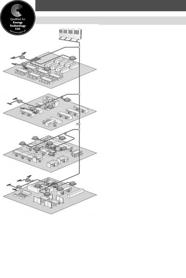
Design Flexibility
The unique refrigerant distribution control allows for a wide variety of piping options:
•Up to 40 indoor units per system
•Allowable height difference between indoor and outdoor units 50 m (outdoor unit above) or 30 m (outdoor unit below)
•Up to 30 m height difference between indoor units
•Equivalent length of 125 m (100 m actual) between outdoor unit and furthest indoor unit
•Vertical distance of up to 4m permitted between outdoor units
•Total pipework network of up to 250 m
Piping Possibilities
The indoor unit network can be designed with Y-joints after headers and headers after headers. The possibilities are endless thanks to the refrigerant distribution system that compensates for the variation in pipe resistance and balances the flow across the entire network.
Y joint branch after header branch |
Header branch after Y joint |
|||||||||||||||||||||||||
(Toshiba unique technology) |
|
|
|
|
|
|
|
|
|
|
|
|
|
|
|
|
|
|||||||||
|
|
|
|
|
|
|
|
|
|
|
|
|
|
|
|
|
||||||||||
|
|
|
|
|
|
|
|
|
|
|
|
|
|
|
|
|
|
|
|
|
|
|
|
|
|
|
|
|
|
|
|
|
|
|
|
|
|
|
|
|
|
|
|
|
|
|
|
|
|
|
|
|
|
|
|
|
|
|
|
|
|
|
|
|
|
|
|
|
|
|
|
|
|
|
|
|
|
|
|
|
|
|
|
|
|
|
|
|
|
|
|
|
|
|
|
|
|
|
|
|
|
|
|
|
|
|
|
|
|
|
|
|
|
|
|
|
|
|
|
|
|
|
|
|
|
|
|
|
|
|
|
|
|
|
|
|
|
|
|
|
|
|
|
|
|
|
|
|
|
|
|
|
|
|
|
|
|
|
|
|
|
|
|
|
|
|
|
|
|
|
|
|
|
|
|
|
|
|
|
|
|
|
|
|
|
|
|
|
|
|
|
|
|
|
|
|
|
|
|
|
|
|
|
|
|
|
|
|
|
|
|
|
|
|
|
Header branch after header branch (Toshiba unique technology)
Expandability
The system is modular so it can be expanded as needed. Installations can also be staged to allow sequential installation. This is ideal for refurbishment situations when disruption of business operation must be minimised. It also allows for flexibility should the floor layout be modified at a later date.
11
General Information
Benefits of the Modular Multi System
Economical
Installation Savings
There are potential installation savings with the MMS, due to the additional network piping possibilities and the reduction in the number of pipes connecting the outdoor units to the indoor network.
Capacity Range
The variation of outdoor unit combinations allows MMS to meet system capacity demands from 22.4 to 128.8 kW (8 to 46 hp) in nineteen increments. This allows the system capacity to match your exact needs, reducing product costs.
Overview of the 19 Modular Multi System Configurations
OUTDOOR SYSTEM |
|
INVERTER |
|
FIXED |
|
|
Total connected code |
|||
CAPACITY |
|
|
28 kW (10 hp) |
22.4 kW (8 hp) |
28 kW (10 hp) |
22.4 kW (8 hp) |
16 kW (6 hp) |
Maximum No. |
|
|
Cooling only (no heating) |
Code |
MM-A0280CT |
MM-A0224CT |
MM-A0280CX |
MM-A0224CX |
MM-A0160CX |
of indoor |
|
|
|
|
|
|||||||||
Cooling |
Heating* |
hp |
MM-A0280HT |
MM-A0224HT |
MM-A0280HX |
MM-A0224HX |
MM-A0160HX |
units |
Min |
Max |
22.4 |
25.0 |
8 |
|
1 |
|
|
|
13 |
4 |
10.8 |
|
|
|
|
|
|
|
|
|
|
|
28.0 |
31.5 |
10 |
1 |
|
|
|
|
16 |
5 |
13.5 |
|
|
|
|
|
|
|
|
|
|
|
38.4 |
43.0 |
14 |
|
1 |
|
|
1 |
16 |
7 |
18.9 |
|
|
|
|
|
|
|
|
|
|
|
44.8 |
50.0 |
16 |
|
1 |
|
1 |
|
18 |
8 |
21.6 |
|
|
|
|
|
|
|
|
|
|
|
50.4 |
56.5 |
18 |
1 |
|
|
1 |
|
18 |
9 |
24.3 |
|
|
|
|
|
|
|
|
|
|
|
56.0 |
63.0 |
20 |
1 |
|
1 |
|
|
20 |
10 |
27.0 |
|
|
|
|
|
|
|
|
|
|
|
60.8 |
68.0 |
22 |
|
1 |
|
1 |
1 |
22 |
11 |
29.7 |
|
|
|
|
|
|
|
|
|
|
|
67.2 |
75.0 |
24 |
|
1 |
|
2 |
|
24 |
12 |
32.4 |
|
|
|
|
|
|
|
|
|
|
|
72.8 |
81.5 |
26 |
1 |
|
|
2 |
|
26 |
13 |
35.1 |
|
|
|
|
|
|
|
|
|
|
|
78.4 |
88.0 |
28 |
1 |
|
1 |
1 |
|
28 |
14 |
37.8 |
|
|
|
|
|
|
|
|
|
|
|
84.0 |
94.5 |
30 |
1 |
|
2 |
|
|
30 |
15 |
40.5 |
|
|
|
|
|
|
|
|
|
|
|
89.6 |
100.0 |
32 |
|
1 |
|
3 |
|
32 |
16 |
43.2 |
|
|
|
|
|
|
|
|
|
|
|
95.2 |
106.5 |
34 |
1 |
|
|
3 |
|
34 |
17 |
45.9 |
|
|
|
|
|
|
|
|
|
|
|
100.8 |
113.0 |
36 |
1 |
|
1 |
2 |
|
36 |
18 |
48.6 |
|
|
|
|
|
|
|
|
|
|
|
106.4 |
119.5 |
38 |
1 |
|
2 |
1 |
|
38 |
19 |
51.3 |
|
|
|
|
|
|
|
|
|
|
|
112.0 |
126.0 |
40 |
1 |
|
3 |
|
|
40 |
20 |
54.0 |
|
|
|
|
|
|
|
|
|
|
|
117.6 |
131.5 |
42 |
1 |
|
|
4 |
|
40 |
21 |
56.7 |
|
|
|
|
|
|
|
|
|
|
|
123.2 |
138.0 |
44 |
1 |
|
1 |
3 |
|
40 |
22 |
59.4 |
|
|
|
|
|
|
|
|
|
|
|
128.8 |
144.5 |
46 |
1 |
|
2 |
2 |
|
40 |
23 |
62.1 |
|
|
|
|
|
|
|
|
|
|
|
* Heating capacities only apply to heat pump systems
Conditions
The capacities are based on Eurovent conditions: Cooling: Indoor air entering temperature 27°C db, 19°C wb, outdoor air temperature 35°C db Heating: Indoor air entering temperature 20°C db, outdoor air temperature 7°C db, 6°C wb
Unit operating range
Indoor |
Outdoor |
Cooling |
Cooling |
|
|
Maximum: 32°C db, 22.5°C wb |
Maximum: 43°C db |
Minimum: 18°C db, 15.5°C wb |
Minimum: -5°C db |
|
|
Relative humidity: |
|
|
|
Maximum: 80% |
|
Heating: |
|
|
|
Maximum: 29°C |
|
Minimum: 15°C |
|
990 mm
1700 mm
750 mm
12
General Information
Benefits of the Modular Multi System |
1 |
|
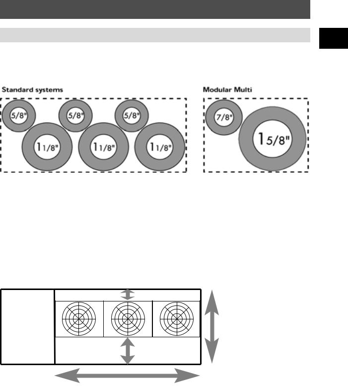
Small Riser Space
Example for a 84 kW (30 hp) system
50% Reduction in Riser Space
Space Saving, Compact Design
The compact Modular Multi outdoor units have a small footprint so they can fit into tight working spaces, thus freeing premium floor space for other usage. A single set of pipes connects the outdoor series to the indoor unit network, minimising the riser space required.
Example for a 84kW (30HP) system
300mm
Smaller
than
1.55m
competitors
10mm |
20mm |
20mm |
10mm |
500mm
3.03m
Units will fit in 90% of the world's lifts
13

General Information
Benefits of the Modular Multi System
Applying the Modular Multi System is easy. The following flowchart outlines the basic steps of the process, which are typical for almost all air conditioning applications.This manual is structured with separate chapters focusing on each of the steps along with a separate chapter on each type of indoor unit.We have also included a chapter which outlines an example of an MMS application.
Zoning
Indoor unit selection
Capacity correction
As with all air conditioning applications, proper zoning is important. Indoor units connected to a common system should have similar loading characteristics, thus minimising the potential for conflicting demand.
Indoor units are selected based on the predicted heat load as well as the style and layout of the space to be air conditioned. Air distribution and sound level characteristics may also be factors for consideration.
Indoor unit capacity will be adjusted based on the expected length and height of pipe runs and environmental conditions.
Outdoor unit selection
Piping design
Controls selection
Wiring design
The outdoor unit capacity is then determined, based on the expected demand.This is calculated by summing the capacity of the indoor network and predicting the peak load.
The piping network for the indoor units will be based on the zoning requirements and building layout. Numerous options are available due to the flexibility of the system.
The controls selection is dependent on the specification. Toshiba has a wide range of control systems available and has collaborated with customers on the development of unique systems to meet specific application requirements.
Each of the indoor and outdoor units will have its own power supply. Control wiring requirements will be determined by the controls selection.
14

Indoor units
Intelligent Indoor Units
The Modular Multi System indoor units are compatible with both the Cooling Only and Heat Pump outdoor |
2 |
units. The MMS dedicated indoor range has precise capacity control. |
Each MMS indoor unit has the following additional components:
•Pressure and temperature sensors to determine the superheat conditions of the refrigerant
•A pulsed modulating valve (PMV) to optimise refrigerant flow
•A printed circuit board to communicate system parameters and demand to the outdoor system
|
Pulsed modulating valve |
Temperature sensors
|
Pressure sensor capillary |
The added intelligence of the indoor units provides precise capacity control without a multi controller unit. Localised sensing of the refrigerant conditions and internal controls provide excellent performance in all conditions.The units compensate for the piping resistances allowing greater flexibility in piping design. Communication between the indoor and outdoor network means greater performance and efficiency as system output closely matches the demand of the indoor network.
Modular Multi System
Very good capacity control because of the indoor unit knows the exact superheat value through constant monitoring of the coil temperature sensors and the pressure sensor. This allows the PMVs to adjust and account for all resistance in the circuit and achieve the desired capacity.
Localised
•Pressure measurement
•Temperature measurement
•Refrigerant flow adjustment
System compensates for high pipe resistance

15

Indoor Units
|
Model Type |
|
Model |
|
Capacity |
|
Cooling |
|
Heating |
|
Height |
|
Width |
|
Depth |
|
Weight |
|
||
|
|
|
|
|
|
|
|
|
|
|||||||||||
|
|
|
|
|
Name |
|
Code |
|
Capacity |
|
Capacity |
|
mm |
|
mm |
|
mm |
|
kg |
|
|
|
|
|
|
|
|
|
|
kW |
|
kW |
|
|
|
|
|
|
|
|
|
|
|
|
|
|
|
|
|
|
|
|
|
|
|
|
|
|
|
|
|
|
|
4-way Cassette* |
|
MM-U056 |
|
1.0 |
|
2.8 |
|
3.2 |
259 |
|
820 |
|
820 |
|
25 |
|
|||
|
|
|
|
|
|
|
1.25 |
|
3.5 |
|
4.0 |
|
|
|
|
|
|
|
|
|
|
|
|
|
|
|
|
1.5 |
|
4.2 |
|
4.8 |
|
|
|
|
|
|
|
|
|
|
|
|
|
|
|
|
1.7 |
|
4.8 |
|
5.4 |
|
|
|
|
|
|
|
|
|
|
|
|
|
|
|
|
2.0 |
|
5.6 |
|
6.4 |
|
|
|
|
|
|
|
|
|
|
|
|
|
|
MM-U080 |
|
2.5 |
|
6.7 |
|
8.0 |
|
|
|
|
|
|
|
|
|
|
|
|
|
|
|
|
3.0 |
|
8.0 |
|
9.6 |
|
|
|
|
|
|
|
|
|
|
|
|
|
|
MM-U112 |
|
3.2 |
|
9.0 |
|
10.2 |
309 |
|
1230 |
|
820 |
|
43 |
|
|
|
|
|
|
|
|
|
4.0 |
|
11.2 |
|
12.8 |
|
|
|
|
|
|
|
|
|
|
|
|
|
|
MM-U140 |
|
5.0 |
|
14.0 |
|
15.8 |
|
|
|
|
|
|
|
|
|
|
|
|
|
|
|
|
|
|
|
|
|
|
|
|
|
|
|
|
|
|
|
Concealed Duct |
|
MM-B056 |
|
1.0 |
|
2.8 |
|
3.2 |
345 |
|
770 |
|
875 |
|
39 |
|
|||
|
|
|
|
|
|
|
1.25 |
|
3.5 |
|
4.0 |
|
|
|
|
|
|
|
|
|
|
|
|
|
|
|
|
1.5 |
|
4.2 |
|
4.8 |
|
|
|
|
|
|
|
|
|
|
|
|
|
|
|
|
1.7 |
|
4.8 |
|
5.4 |
|
|
|
|
|
|
|
|
|
|
|
|
|
|
|
|
2.0 |
|
5.6 |
|
6.4 |
|
|
|
|
|
|
|
|
|
|
|
|
|
|
MM-B080 |
|
2.5 |
|
6.7 |
|
8.0 |
345 |
|
1070 |
|
875 |
|
53 |
|
|
|
|
|
|
|
|
|
3.0 |
|
8.0 |
|
9.6 |
|
|
|
|
|
|
|
|
|
|
|
|
|
|
MM-B112 |
|
3.2 |
|
9.0 |
|
10.2 |
345 |
|
1420 |
|
875 |
|
58 |
|
|
|
|
|
|
|
|
|
4.0 |
|
11.2 |
|
12.8 |
|
|
|
|
|
|
|
|
|
|
|
|
|
|
MM-B140 |
|
5.0 |
|
14.0 |
|
15.8 |
345 |
|
1420 |
|
875 |
|
62 |
|
|
|
|
|
|
|
|
|
|
|
|
|
|
|
|
|
|
|
|
|
|
|
|
2-way Cassette |
|
MM-TU028 |
|
0.8 |
|
2.2 |
|
2.6 |
190 |
|
910 |
|
480 |
|
23 |
|
|||
|
|
|
|
|
|
|
1.0 |
|
2.8 |
|
3.2 |
|
|
|
|
|
|
|
|
|
|
|
|
|
|
MM-TU042 |
|
1.25 |
|
3.5 |
|
4.0 |
|
|
|
|
|
|
|
|
|
|
|
|
|
|
|
|
1.5 |
|
4.2 |
|
4.8 |
|
|
|
|
|
|
|
|
|
|
|
|
|
|
MM-TU056 |
|
1.7 |
|
4.8 |
|
5.4 |
|
|
|
|
|
|
|
|
|
|
|
|
|
|
|
|
2.0 |
|
5.6 |
|
6.4 |
|
|
|
|
|
|
|
|
|
|
|
|
|
|
|
|
|
|
|
|
|
|
|
|
|
|
|
|
|
|
|
High Wall* |
|
MM-K/KR042 |
|
0.8 |
|
2.2 |
|
2.6 |
372 |
|
1150 |
|
226 |
|
20 |
|
|||
|
|
|
|
|
|
|
1.0 |
|
2.8 |
|
3.2 |
|
|
|
|
|
|
|
|
|
|
|
|
|
|
|
|
1.25 |
|
3.5 |
|
4.0 |
|
|
|
|
|
|
|
|
|
|
|
|
|
|
|
|
1.5 |
|
4.2 |
|
4.8 |
|
|
|
|
|
|
|
|
|
|
|
|
|
|
MM-K/KR056 |
|
1.7 |
|
4.8 |
|
5.4 |
|
|
|
|
|
|
|
|
|
|
|
|
|
|
|
|
2.0 |
|
5.6 |
|
6.4 |
|
|
|
|
|
|
|
|
|
|
|
|
|
|
MM-K/KR080 |
|
2.5 |
|
6.7 |
|
8.0 |
372 |
|
1478 |
|
226 |
|
26 |
|
|
|
|
|
|
|
|
|
3.0 |
|
8.0 |
|
9.6 |
|
|
|
|
|
|
|
|
|
|
Ceiling* |
|
MM-C/CR042 |
|
0.8 |
|
2.2 |
|
2.6 |
188 |
|
1030 |
|
640 |
|
24 |
|
|||
|
|
|
|
|
|
|
1.0 |
|
2.8 |
|
3.2 |
|
|
|
|
|
|
|
|
|
|
|
|
|
|
|
|
1.25 |
|
3.5 |
|
4.0 |
|
|
|
|
|
|
|
|
|
|
|
|
|
|
|
|
1.5 |
|
4.2 |
|
4.8 |
|
|
|
|
|
|
|
|
|
|
|
|
|
|
MM-C/CR056 |
|
1.7 |
|
4.8 |
|
5.4 |
|
|
|
|
|
|
|
|
|
|
|
|
|
|
|
|
2.0 |
|
5.6 |
|
6.4 |
|
|
|
|
|
|
|
|
|
|
|
|
|
|
MM-C/CR080 |
|
2.5 |
|
6.7 |
|
8.0 |
188 |
|
1230 |
|
640 |
|
28 |
|
|
|
|
|
|
|
|
|
3.0 |
|
8.0 |
|
9.6 |
|
|
|
|
|
|
|
|
|
|
|
|
|
|
MM-C/CR 112 |
|
4.0 |
|
11.2 |
|
12.8 |
240 |
|
1430 |
|
640 |
|
39 |
|
|
|
|
|
|
|
MM-C/CR140 |
|
5.0 |
|
14.0 |
|
15.8 |
240 |
|
1630 |
|
640 |
|
44 |
|
|
|
Floor Low Wall* |
|
MM-S/SR056 |
|
1.0 |
|
2.8 |
|
3.2 |
640 |
|
1030 |
|
188 |
|
24 |
|
|||
|
|
|
|
|
|
|
1.25 |
|
3.5 |
|
4.0 |
|
|
|
|
|
|
|
|
|
|
|
|
|
|
|
|
1.5 |
|
4.2 |
|
4.8 |
|
|
|
|
|
|
|
|
|
|
|
|
|
|
|
|
1.7 |
|
4.8 |
|
5.4 |
|
|
|
|
|
|
|
|
|
|
|
|
|
|
|
|
2.0 |
|
5.6 |
|
6.4 |
|
|
|
|
|
|
|
|
|
|
|
|
|
|
MM-S/SR080 |
|
2.5 |
|
6.7 |
|
8.0 |
640 |
|
1230 |
|
188 |
|
28 |
|
|
|
|
|
|
|
|
|
3.0 |
|
8.0 |
|
9.6 |
|
|
|
|
|
|
|
|
|
|
|
|
|
|
|
|
|
|
|
|
|
|
|
|
|
|
|
|
|
|
|
Chassis |
|
MM-N028 |
|
0.8 |
|
2.2 |
|
2.6 |
600 |
|
750 |
|
230 |
|
21 |
|
|||
|
|
|
|
|
|
|
1.0 |
|
2.8 |
|
3.2 |
|
|
|
|
|
|
|
|
|
|
|
|
|
|
MM-N042 |
|
1.25 |
|
3.5 |
|
4.0 |
600 |
|
1050 |
|
230 |
|
25 |
|
|
|
|
|
|
|
|
|
1.5 |
|
4.2 |
|
4.8 |
|
|
|
|
|
|
|
|
|
|
|
|
|
|
MM-N056 |
|
1.7 |
|
4.8 |
|
5.4 |
600 |
|
1050 |
|
230 |
|
29 |
|
|
|
|
|
|
|
|
|
2.0 |
|
5.6 |
|
6.4 |
|
|
|
|
|
|
|
|
|
|
|
|
|
|
MM-N080 |
|
2.5 |
|
6.7 |
|
8.0 |
|
|
|
|
|
|
|
|
|
|
|
|
|
|
|
|
3.0 |
|
8.0 |
|
9.6 |
|
|
|
|
|
|
|
|
|
|
|
|
|
|
|
|
|
|
|
|
|
|
|
|
|
|
|
|
|
|
|
Slim Duct |
|
MM-SB028 |
|
0.8 |
|
2.2 |
|
2.6 |
220 |
|
800 |
|
500 |
|
22 |
|
|||
|
|
|
|
|
|
|
1.0 |
|
2.8 |
|
3.2 |
|
|
|
|
|
|
|
|
|
|
|
|
|
|
|
|
|
|
|
|
|
|
|
|
|
|
|
|
|
|
* These units are available with infrared remote control. For the four-way cassette unit a separate infrared panel is required.
16

Indoor Units
De-rating
1.The Modular Multi indoor units have a de-rating option that can be implemented to match actual load
requirements.The full output range including the de-rated units is outlined in the table shown. |
2 |
2.When an indoor unit is derated the initial opening pulse of the indoor unit PMV is adjusted according to the capacity rating.
3a. In cooling code, the PMV pulse is then adjusted along with the inverter compressor frequency to ensure optimum superheat conditions at each indoor unit.
3b. In heating mode, the PMV pulse is then adjusted along with the outdoor unit PMV & inverter frequency to ensure the optimum subcooling condition at each indoor unit.
Total Cooling kW |
2.2 |
|
2.8 |
3.5 |
4.2 |
4.8 |
5.6 |
6.7 |
8.0 |
9.0 |
11.2 |
14.0 |
|
Sensible Cooling kW |
1.7 |
|
2.1 |
2.6 |
3.2 |
3.6 |
4.2 |
5.0 |
6.0 |
6.8 |
8.4 |
10.5 |
|
|
|
|
|
|
|
|
|
|
|
|
|
|
|
4-way Cassette |
|
|
|
|
|
|
|
|
|
|
|
|
|
2-way Cassette |
|
|
|
|
|
|
|
|
|
|
|
|
|
|
|
|
|
|
|
|
|
|
|
|
|
|
|
Duct/Slim Duct* |
|
|
|
|
|
|
|
|
|
|
|
|
|
High Wall |
|
|
|
|
|
|
|
|
|
|
|
|
|
Ceiling |
|
|
|
|
|
|
|
|
|
|
|
|
|
|
|
|
|
|
|
|
|
|
|
|
|
|
|
Chassis |
|
|
|
|
|
|
|
|
|
|
|
|
|
Floor/Low Wall |
|
|
|
|
|
|
|
|
|
|
|
|
|
Heating kW |
2.6 |
|
3.2 |
4.0 |
4.8 |
5.4 |
6.4 |
8.0 |
9.6 |
10.2 |
12.8 |
15.8 |
|
|
|
|
|
|
|
|
|
|
|
|
|
|
|
Capacity Code Setting |
0.8 |
|
1.0 |
1.25 |
1.5 |
1.7 |
2.0 |
2.5 |
3.0 |
3.2 |
4.0 |
5.0 |
|
STANDARD CAPACITY SETTING |
|
OUTPUT ACHIEVED BY DE-RATING |
|
|
|
|
|
||||||
* Slim Duct indoor unit available in 2.8 kW standard and 2.2 kW de-rated capacities |
|
|
|
|
|
|
|||||||
Note: Indoor unit system capacity may be between 50 and 135% of the connected outdoor units. |
|
|
|
|
|||||||||
17

Indoor Units
Part Numbering
The indoor unit part numbering system is defined as follows:
|
|
|
MM |
- |
U |
|
|
056 |
|
|
|
|||||||
|
|
|
|
|
|
|
|
|
|
|
|
|
|
|
|
|
||
|
|
|
|
|
|
|
|
|
|
|
|
|||||||
|
|
|
|
|
|
|
|
|
|
|
|
|
|
|
|
|
|
|
Product Designation |
|
|
Unit Type |
|
|
|
Cooling Capacity (STD) |
|||||||||||
MM Modular Multi |
|
|
B |
Duct |
|
|
|
028 |
2.8 kW |
|||||||||
|
|
|
|
C |
Ceiling |
|
|
|
042 |
4.2 kW |
||||||||
|
|
|
||||||||||||||||
|
|
|
|
F |
Floor |
|
|
|
056 |
5.6 kW |
||||||||
|
|
|
|
K |
High Wall |
|
|
|
080 |
8.0 kW |
||||||||
|
|
|
|
N |
Chassis |
|
|
|
112 |
11.2 kW |
||||||||
|
|
|
|
S |
Low Wall |
|
|
|
140 |
14.0 kW |
||||||||
|
|
|
|
SB |
Slim Duct |
|
|
|
|
|
|
|||||||
|
|
|
|
|
|
|
|
|
|
|||||||||
|
|
|
|
TU |
2-way Cassette |
|
|
|
|
|
|
|||||||
|
|
|
|
U |
4-way Cassette |
|
|
|
|
|
|
|||||||
|
|
|
|
An R next to the unit |
|
|
|
|
|
|
||||||||
|
|
|
|
designation indicates a unit |
|
|
|
|
||||||||||
|
|
|
|
with an infrared controls |
|
|
|
|
|
|
||||||||
|
|
|
|
option |
|
|
|
|
|
|
|
|
|
|
|
|
||
|
|
|
|
|
|
|
|
|
|
|
|
|
|
|
|
|
|
|
Location Precautions
Avoid installing the indoor unit in the following locations:
•Where there is danger of flammable gas leakages.
•Where there are high concentrations of oil.
•Where the atmosphere contains an excess of salt.
•Where high concentrations of organic solvent are present.
•Where a machine that generates high frequencies is operated.
•Where the unit will not be horizontal.
•Where the floor/wall/ceiling structure is unable to support the weight of the unit.
•Where it is not possible to fix the unit hangers, e.g. window glass.
Locate the unit to ensure uniform circulation of conditioned air.
18

Four-Way Cassette
• Slim design
• Highly efficient drain pump
• 2-, 3- and 4-way air distribution
3
•Ultra quiet
•Slim one-piece easy-to-clean panel
•Threaded drain connection as standard
•Long-life washable air filter
•Synchronised motor-driven louvres
•Fresh air intake facility
•Branch duct option
•Easy access to components
•Infrared controls option via panel RBC-UxxxPGR
•Modular Multi dedicated indoor unit. Monitors pressure and temperature and adjusts refrigerant flow to optimise performance locally.
MODEL |
|
MM-U056 |
|
|
|
MM-U080 |
MM-U112 |
MM-U140 |
|||
Cooling Capacity |
kW |
2.8 |
3.5 |
4.2 |
4.8 |
5.6 |
6.7 |
8.0 |
9.0 |
11.2 |
14.0 |
|
|
|
|
|
|
|
|
|
|
|
|
Heating Capacity |
kW |
3.2 |
4.0 |
4.8 |
5.4 |
6.4 |
8.0 |
9.6 |
10.2 |
12.8 |
15.8 |
|
|
|
|
|
|
|
|
|
|
|
|
Capacity Code |
|
1.0* |
1.25* |
1.5* |
1.7* |
2.0 |
2.5* |
3.0 |
3.2* |
4.0 |
5.0 |
|
|
|
|
|
|
|
|
|
|
|
|
Sensible Cooling |
kW |
2.1 |
2.6 |
3.2 |
3.6 |
4.2 |
5.0 |
6.0 |
6.8 |
8.4 |
10.5 |
|
|
|
|
|
|
|
|
|
|
|
|
Airflow Rate H |
m3/h |
1020 |
1020 |
1020 |
1020 |
1020 |
1260 |
1260 |
1750 |
1750 |
1860 |
Airflow Rate M |
m3/h |
890 |
890 |
890 |
890 |
890 |
1140 |
1140 |
1520 |
1520 |
1620 |
Airflow Rate L |
m3/h |
830 |
830 |
830 |
830 |
830 |
1020 |
1020 |
1360 |
1360 |
1510 |
Unit Weight |
kg |
25 |
25 |
25 |
25 |
25 |
25 |
25 |
43 |
43 |
43 |
|
|
|
|
|
|
|
|
|
|
|
|
Height |
mm |
259 |
259 |
259 |
159 |
259 |
259 |
259 |
309 |
309 |
309 |
|
|
|
|
|
|
|
|
|
|
|
|
Width |
mm |
820 |
820 |
820 |
820 |
820 |
820 |
820 |
1230 |
1230 |
1230 |
Depth |
mm |
820 |
820 |
820 |
820 |
820 |
820 |
820 |
820 |
820 |
820 |
Air Filter |
|
Washable, 500 µm |
|
|
|
|
|
|
|
||
Gas Connection |
mm |
ø12.7 (1/2”) |
|
|
|
ø15.9 (5/8”) |
ø19.0 (3/4”) |
ø19.0 (3/4”) |
|||
Liquid Connection |
mm |
ø 6.4 (1/4”) |
|
|
|
ø 9.5 (3/8”) |
ø 9.5 (3/8”) |
ø 9.5 (3/8”) |
|||
Drain Connection |
mm |
Male 25.4 (1” BSP) |
|
|
|
|
|
|
|
||
PANEL TYPE |
|
RBC-U264PG/PGR**(W)-E |
|
|
|
RBC-U464PG/PGR**(W)-E |
|
|||||
|
|
|
|
|
|
|
|
|
|
|||
Air Filter |
|
Washable - 500 µm |
|
|
|
|
|
Washable - 500 µm |
|
|||
Panel Weight |
kg |
6 |
6 |
6 |
6 |
6 |
6 |
6 |
8 |
8 |
8 |
8 |
|
|
|
|
|
|
|
|
|
|
|
|
|
Panel Height |
mm |
20 |
20 |
20 |
20 |
20 |
20 |
20 |
20 |
20 |
20 |
20 |
|
|
|
|
|
|
|
|
|
|
|
|
|
Panel Width |
mm |
940 |
940 |
940 |
940 |
940 |
940 |
940 |
1350 |
1350 |
1350 |
1350 |
Panel Depth |
mm |
940 |
940 |
940 |
940 |
940 |
940 |
940 |
940 |
940 |
940 |
940 |
*Setting shown is de-rated and adjustment must be made during installation/commissioning.
**Panel with R designation has infrared controls
19

Four-Way Cassette
Acoustic Data
|
|
|
|
|
|
|
|
|
Sound |
|
MM-U056 |
Sound Power Level (SWL) - dB |
|
|
|
|
|
Pressure Level |
|||
|
125 Hz |
250 Hz |
500 Hz |
1000 Hz |
2000 Hz |
4000 Hz |
8000 Hz |
SWL |
SPL (dBA) |
NC* |
Low |
38.3 |
36.5 |
27.7 |
24.8 |
21.9 |
16.1 |
16.5 |
37.5 |
32 |
22 |
Med |
39.5 |
38.8 |
30.2 |
28.7 |
23.3 |
16.4 |
16.6 |
39.7 |
35 |
24 |
High |
41.1 |
41.2 |
33.6 |
32.6 |
26.4 |
18.7 |
17.8 |
42.7 |
38 |
29 |
|
|
|
|
|
|
|
|
|
|
|
MM-U080 |
|
|
|
|
|
|
|
|
|
|
|
125 Hz |
250 Hz |
500 Hz |
1000 Hz |
2000 Hz |
4000 Hz |
8000 Hz |
SWL |
SPL (dBA) |
NC* |
|
|
|
|
|
|
|
|
|
|
|
Low |
40.5 |
40.8 |
33.1 |
35.7 |
28.4 |
20.0 |
21.5 |
42.9 |
35 |
32 |
Med |
43.1 |
45.4 |
38.1 |
36.9 |
30.4 |
22.5 |
21.9 |
46.4 |
39 |
33 |
High |
44.0 |
48.1 |
40.7 |
39.4 |
32.6 |
25.0 |
21.3 |
48.9 |
43 |
36 |
|
|
|
|
|
|
|
|
|
|
|
MM-U112 |
|
|
|
|
|
|
|
|
|
|
|
125 Hz |
250 Hz |
500 Hz |
1000 Hz |
2000 Hz |
4000 Hz |
8000 Hz |
SWL |
SPL (dBA) |
NC* |
Low |
45.4 |
41.6 |
37.7 |
33.1 |
26.0 |
18.9 |
20.1 |
44.4 |
37 |
29 |
Med |
50.4 |
44.1 |
40.6 |
37.1 |
30.0 |
21.8 |
20.2 |
47.4 |
40 |
34 |
High |
52.6 |
44.9 |
41.5 |
38.5 |
31.5 |
23.8 |
20.5 |
48.6 |
42 |
35 |
MM-U140 |
|
|
|
|
|
|
|
|
|
|
|
125 Hz |
250 Hz |
500 Hz |
1000 Hz |
2000 Hz |
4000 Hz |
8000 Hz |
SWL |
SPL (dBA) |
NC* |
|
|
|
|
|
|
|
|
|
|
|
Low |
47.8 |
45.7 |
42.9 |
36.5 |
29.6 |
25.1 |
19.1 |
47.7 |
40 |
33 |
Med |
51.8 |
46.8 |
45.7 |
40.0 |
32.0 |
26.0 |
19.8 |
50.0 |
43 |
36 |
High |
52.8 |
47.4 |
45.6 |
40.5 |
32.9 |
26.8 |
19.9 |
50.6 |
45 |
37 |
* For all practical purposes NR and NC curves may be regarded as mutually interchangeable. (Ref: CIBSE Guide Vol. B, page12-4. )
dB(A) |
50 |
MM-U056 |
|
|
|
dB(A) |
50 |
||
|
|
|
|
|
|
||||
40 |
|
|
|
|
|
|
40 |
||
Level |
|
|
|
|
NC-40 |
|
Level |
||
30 |
|
|
|
|
|
|
30 |
||
Pressure |
|
|
|
|
NC-30 |
H |
Pressure |
||
|
|
|
|
|
|
M |
|
||
20 |
|
|
|
|
|
L |
20 |
||
|
|
|
|
NC-20 |
|
||||
|
|
|
|
|
|
|
|||
|
|
|
|
|
|
|
|
||
Sound |
10 |
|
|
|
|
NC-10 |
|
Sound |
10 |
|
|
|
|
|
|
|
|||
0 |
|
|
|
|
|
|
0 |
||
|
125 |
250 |
500 |
1000 |
2000 4000 8000 |
|
|
||
Frequency (Hz)
dB(A) |
50 |
MM-U112 |
|
|
|
dB(A) |
50 |
||
|
|
|
|
|
|
||||
40 |
|
|
|
|
|
|
40 |
||
Level |
|
|
|
|
NC-40 |
|
Level |
||
30 |
|
|
|
|
|
H |
30 |
||
|
|
|
|
|
M |
||||
Pressure |
|
|
|
|
NC-30 |
Pressure |
|||
|
|
|
|
|
|
L |
|
||
20 |
|
|
|
|
NC-20 |
|
20 |
||
|
|
|
|
|
|
|
|||
|
|
|
|
|
|
|
|
||
Sound |
10 |
|
|
|
|
NC-10 |
|
Sound |
10 |
|
|
|
|
|
|
|
|||
0 |
|
|
|
|
|
|
0 |
||
|
125 |
250 |
500 |
1000 |
2000 4000 8000 |
|
|
||
MM-U080 |
|
|
|
||
|
|
|
|
NC-40 |
H |
|
|
|
|
|
|
|
|
|
|
|
M |
|
|
|
|
NC-30 |
L |
|
|
|
|
|
1.5m |
|
|
|
|
NC-20 |
Microphone |
|
|
|
|
|
|
|
|
|
|
NC-10 |
|
125 |
250 |
500 |
1000 |
2000 4000 8000 |
|
Frequency (Hz)
MM-U140 |
|
|
|
||
|
|
|
|
NC-40 |
H |
|
|
|
|
M |
|
|
|
|
|
|
|
|
|
|
|
|
L |
|
|
|
|
NC-30 |
|
|
|
|
|
NC-20 |
|
|
|
|
|
NC-10 |
|
125 |
250 |
500 |
1000 |
2000 4000 8000 |
|
Frequency (Hz) |
Frequency (Hz) |
20

Four-Way Cassette
Air Distribution Control
Conditioned air can be distributed through 2, 3 or 4 sides of the unit to optimise the flow distribution in a room. Insulation blocks are included with the unit to close off the airflow to certain sides of the unit.The diagram below defines which sides of the unit may be closed for each of the capacities.
Choose the number of airflows that are required, depending on the shape of the room and the location of |
3 |
|||||||||||||||
the indoor unit. |
|
|
|
|
|
|
|
|
|
|
|
|
||||
|
|
|
|
|
|
|
|
|
|
|
|
|
||||
|
|
|
|
|
|
|
|
|
|
|
||||||
|
MM-U056/U080 |
|
|
|
MM-U112/U140 |
|
||||||||||
|
|
|
|
|
|
|
|
|
|
|
|
|
|
|
|
|
|
|
|
|
|
|
|
|
|
|
|
|
|
|
|
|
|
|
|
|
|
|
|
|
|
|
|
|
|
|
|
|
|
|
3-way |
3-way |
3-way |
3-way |
3-way |
2-way |
3-way |
2-way |
2-way |
•It is not possible to block the airflow from the longer sides of the unit (U112/U140).
• Insert insulation blocks, which are supplied as
accessories, at each side where the airflow is Insulation Block not required as shown in the diagram
opposite.
In addition, a motorised louvre facility allows the air to be directed in either a pre-set or a sweep pattern. Cassettes also have a branch duct facility for better air distribution in irregular shaped rooms.The combination of these two features gives the occupants total control over air movement within the room, via an easy-to-use remote controller.
21
Four-Way Cassette
Air Distribution
Note: Air velocity data collected at high fan speed.
MM-U056
Air velocity (m/s)
2.7m
(m) |
2 |
|
|
|
|
|
|
Height |
|
1.0 |
|
1 |
0.5 |
|
|
|
|
||
|
|
|
|
|
|
0.3 |
0.1 |
|
|
|
MM-U080
Air velocity (m/s)
2.7m
(m) |
2 |
|
|
|
|
|
|
Height |
|
1.0 |
|
1 |
0.5 |
0.1 |
|
|
|
||
|
|
|
|
|
|
0.3 |
|
0 |
1 |
2 |
3 |
4 |
5 |
0 |
1 |
2 |
3 |
4 |
5 |
|
Distance (m) |
|
|
|
Distance (m) |
|
|
||||
MM-U112 |
|
|
|
|
MM-U140 |
|
|
|
|
||
|
Air velocity (m/s) |
|
|
|
Air velocity (m/s) |
|
|||||
2.7m
(m) |
2 |
Height |
1 |
|
0
|
|
|
|
|
2.7m |
|
|
|
|
|
|
|
1.0 |
|
|
|
(m) |
2 |
|
|
|
|
|
|
|
|
|
|
Height |
1 |
1.0 |
|
|
|
|
|
0.5 |
|
|
|
|
|
|
|
|
0.1 |
|
|
|
|
|
|
|
|
0.5 |
|
|
||
|
|
|
|
|
|
|
|
|
|
|
|
|
|
0.3 |
|
0.1 |
|
|
|
|
0.3 |
|
|
1 |
2 |
3 |
4 |
5 |
|
0 |
1 |
2 |
3 |
4 |
5 |
Distance (m) |
Distance (m) |
Design Features
Flexible Air Distribution
Conditioned air can be distributed through 2, 3 or 4 sides of the unit. In addition, a motorised louvre facility allows the air to be directed in either a pre-set or a sweep pattern. Cassettes also have a branch duct facility for better air distribution in irregular shaped rooms.The combination of these two features gives the occupants total control over air movement within the room via an easy-to-use remote controller.
Fresh Air Facility
An additional advantage of Toshiba’s 4-way cassettes is that outdoor air, as well as conditioned air, can be introduced into the room. (Tempering to 15°C minimum is recommended.)
Quiet Operation
Noise levels have been reduced dramatically, thanks to the specially designed fan inlet that smoothes the airstream as it flows into an aerofoil fan and aerodynamic louvres.
Performance Tuning
Units are preset to a standard setting, however capacity code adjustments can be made to optimise cooling or heating.
Precise Capacity Control
Each indoor unit has pressure and temperature sensors for localised monitoring of refrigerant condition. A pulsed modulating valve (PMV) controls the refrigerant flow and the capacity demand is communicated to the outdoor system. This ensures excellent performance at all conditions. A 3-speed fan controls the cooled airflow volume automatically or manually (4-speed heating mode). Even at the highest fan speed, the unit is quiet in operation.
Easy to Install and Maintain
The 4-way cassette can be concealed within most ceiling voids, with an ultra-thin 20 mm grille. This onepiece panel is easy to install. Its surface is easy to wipe clean, a feature it shares with the synchronised louvre blades.The long-life washable filter also minimises maintenance.
22

Four-Way Cassette
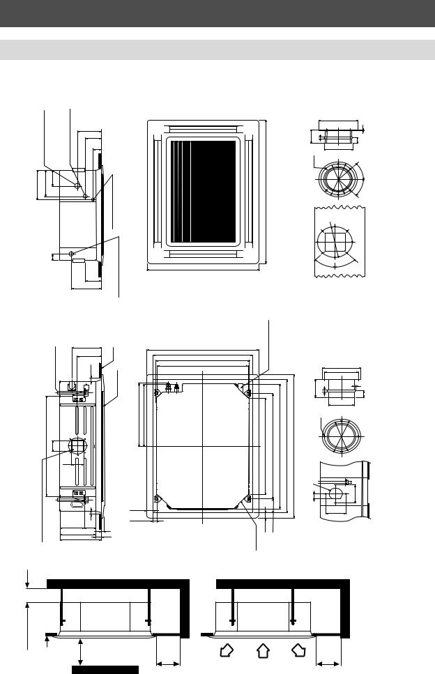
Dimensional Drawings
MM-U056, MM-U080
|
connection |
|
connection |
|
200 |
|
|
|
Refrigerantflare |
|
Refrigerantflare |
|
|
|
|
|
A)ø(Gas |
ø(LiquidB) |
140 |
|
|
||
|
73 |
|
|
||||
|
|
|
|
|
|
|
|
185 |
170 |
100 |
|
|
|
holes) |
|
|
|
|
|
|
|
connection plate3xø20 |
|
|
|
|
|
|
|
Wiring (Gland |
(25.4mmBSPthreadedconnection) |
|
|
80 |
|
|
138 |
pipeDrainconnection |
|
|
|
|
|
|
|
|
|
|
|
|
|
|
240 |
|
|
|
246.5 |
Ceiling |
|
|
195 |
|
|
|
|
|
|
4-M10 |
|
|
|
Hangingbolts |
|
|
|
106 |
|
|
sides) |
106 |
|
(both150ø |
|
|
|
||
|
30 |
|
forsideducts |
259 |
|
20 |
kout |
|
39 |
Knoc |
|
160 |
138 |
|
|
|
|
|
|
|
298 |
|
|
80 |
10 |
|
4-ø6 |
32 ø 100
Note: All dimensions are in mm.
|
940 |
940 (P anel dimension) |
|
880 (Ceiling opening) |
|
820 (External cassette dimension) |
|
800 (Hanger bolt pitch) |
|
195 |
268 |
405 |
400 |
536
|
40 |
|
|
|
|
|
30 |
|
|
|
|
ø 144 |
|
|
ø 200 |
|
|
|
|
6 |
|
||
|
ø 30 |
|
|
|
|
|
|
|
|
|
|
|
2 |
80 |
10 |
30 |
|
|
30 |
|
|
ø 150 |
|
|
|
ø6 |
|
|
|
|
ø 97 |
|
° |
|
|
|
6- |
|
|
||
|
|
|
|
||
|
|
|
|
45 |
|
|
size |
|
|
180 |
size |
|
|
|
ø |
||
|
ductinletairFresh |
|
180ø |
ductoutletSide |
|
|
|
45° |
|||
130 |
|
|
|
|
|
|
ø |
|
|
|
|
ø |
144 |
|
|
|
|
|
|
|
|
|
|
|
130 |
|
|
|
|
|
|
|
° |
45° |
|
130 |
|
45 |
|
|
|
940
Condensate pipe 1 ″ BSP threaded connection
536 |
620(Hangerboltpitch) |
(Externalcassettedimension) |
880(Ceilingopening) |
940(Paneldimension) |
|
|
820 |
|
|
inlet |
130 |
30 |
reshair |
|
|
F |
|
|
|
|
|
MM-U080 |
15.9(5/8”) |
6.4(1/4”) |
U056 U080 |
12.7(1/2) 15.9(5/8) |
6.4(1/4) 6.4(1/4) |
MM-U056 |
12.7(1/2”) |
6.4(1/4”) |
Model(MM-) |
øA |
øB Dimensions mm |
øA |
øB |
|
3
23
Four-Way Cassette
Dimensional Drawings
MM-U112, MM-U140
|
Refrigerantflareconnection |
(Gasside19(3/4)) |
185 |
170 |
100 |
80
Hanging bolts 4-M10
941 |
106 |
Knock out for side ducts ø 150 (both sides)
flareconnection |
9.5(3/8)) |
140 |
|
Refrigerant |
side(Liquid |
200 |
|
73 |
|||
|
|
138
240
246.5 202 30
106
|
30 |
210 |
138 |
309 |
|
348 |
|
|
|
|
|
|
|
|
80 |
10 |
|
|
|
|
|
|
|
6-ø6 |
|
connection plate3xø20holes) |
|
|
1350 |
|
|
|
|
|
Wiring (Gland |
|
|
|
|
|
|
|
|
connection) |
|
|
|
|
|
|
|
|
connectionpipeDrain BSP.4mm(25″threaded |
940 |
|
|
|
|
|
|
|
|
|
|
|
|
|
|
|
|
|
|
BSP |
|
|
|
|
|
|
Ceiling |
940 (P anel dimension) |
Condensatepipe1″ threadedconnection |
|
|
|
|
|
|
|
880 (Ceiling opening) |
|
|
|
|
|
|
|
|
820 (External cassette dimension) |
|
|
|
|
|
|
|
|
800 (Hanger bolt pitch) |
|
|
|
|
|
|
|
Ceilingpanel |
|
|
|
|
|
|
80 |
10 |
|
610 605 |
|
940 |
1030(Hangerboltpitch) |
(Externalcassettedimension) |
1290(Ceilingopening) |
1350(Panelopening) |
4-ø6 |
|
|
|
|
|
1230 |
|
100 |
|
|
|
|
|
|
|
|
ø |
|
|
|
|
|
|
|
|
32 |
|
|
30 |
|
|
|
|
|
|
|
|
40 |
|
130 |
|
|
|
|
|
20 |
inlet |
30 |
|
|
|
|
|
|
air |
|
|
|
|
|
|
|
|
39 |
|
|
|
|
|
|
|
|
|
Fresh |
|
|
|
|
|
|
|
ø 180
45 °
ø 200 |
|
6 |
|
30 |
|
ø 150 |
|
45° |
size |
ø180 |
outletduct |
45° |
|
|
Side |
45 °
|
ø 144 |
|
|
|
ø 30 |
|
|
|
|
2 |
|
|
|
30 |
|
|
ø 97 |
|
|
130 |
ductsize |
||
inlet |
|||
|
ø |
||
ø |
144 |
air |
|
|
|||
|
|
Fresh |
|
|
|
130 |
|
130 |
|
||
15mmormore |
|
Ceiling |
1000 mm or more |
|
|
1000 mm |
1000 mm |
Obstacle |
or more |
or more |
Note: All dimensions are in mm.
24

Four-Way Cassette
Drain Piping
Precautions
Ensure that the entire indoor drain piping is correctly heat-insulated otherwise condensation may result. Also, insulate the section which connects it to the indoor unit.
If nylon cable ties are used to secure the insulation, take precautions not to over-tighten them because |
3 |
|||||
deformation of the heat insulation will reduce its effectiveness. |
||||||
|
||||||
Take care not to apply excessive force or pressure at the unit side where the drain piping exits the indoor |
|
|||||
unit. |
|
|
|
|
|
|
The drain piping must be placed on a downward gradient (1/100 or greater) and there should be no |
|
|||||
upward or downward curves in the pipe which obstruct the drainage, unless a drain pump is employed. |
|
|||||
The drain pipe should be sufficiently supported to prevent warpage. |
|
|||||
When one drainage system is used for a multiple of indoor units, install the piping as shown below: |
|
|||||
|
15-20 m |
Upward curve |
Make this distance as long as possible – approx. 100 mm |
|
||
|
Support clamp X |
|
||||
|
|
|
|
|||
Insulator |
|
|
|
|||
|
|
Downward curve |
|
Downward gradient 1/100 or greater |
|
|
Downward gradient 1/100 or greater |
|
|
||||
|
|
|
||||
Piping Material and Heat Insulator |
|
|
|
|||
|
Heat Insulator* |
Hard PVC pipe** |
* |
Heat Insulator: |
|
|
|
|
|
|
Polyethylene foam (thickness 6 mm) |
|
|
|
|
|
** |
Piping Material: |
|
|
|
|
|
|
Hard PVC pipe nominal diameter inside Ø20 mm |
|
|
Drain pan |
Drain hose |
Hard PVC adhesive |
|
|
|
|
Connection to the unit is via a 1” BSP male connection – to ensure a waterproof seal, PTFE thread tape should be used.The maximum lift of the condensate pump from the drain outlet is 360 mm and the maximum overall lift from the underside of the ceiling to the centre of the drain piping is 600 mm.These values must not be exceeded, otherwise unit flooding will occur when the drain pump is switched off.
360 mm (max.) 600 mm (max.)
100 mm (max.)
Cassette
Ceiling
25

Four-Way Cassette
Fresh Air Inlet
These models have a cut out hole in the cabinet to enable outdoor air to enter the indoor unit at a maximum rate of 10% of selected air by volume. Before installing the unit, remove the cut out hole and insulation block and fit a spigot to connect the duct before hanging the unit. (Tempering incoming air to 15°C minimum is recommended.)
Details of Cut-Out Hole
The cut out hole is a ‘D’ shape half-cut hole on the side of the indoor unit, located on the side opposite the pipework.
Drain Pan
Insulation Block
Fresh Air Inlet
Add a spigot to the side of the indoor unit and attach using the 4 screw holes as shown below:
32 ø100
130
ø144
130
4-ø6 |
80 |
|
|
|
|
|
10 |
|
ø130 |
ø130 |
ø144 |
ø97 |
||
|
30 |
|
|
2 |
|
Note: All dimensions are in mm.
26

Four-Way Cassette
Air Outlet Duct
A portion of airflow can be redirected via the air outlet duct. Before installing the unit, remove the cut out hole and fit a spigot to connect the duct before hanging the unit.
Details of Cut-Out Hole
The cut out hole is a rectangular shape half-cut hole located on two sides if the unit. |
3 |
Air outlet duct
Add a spigot to the side of the indoor unit and attach using the 6 screw holes as shown:
45°
ø 180
45°
45°
6-ø6 |
80 |
|
|
|
10 |
ø180
ø150 |
ø200 |
45° |
30 |
|
6
Air Outlet Spigot (ø150)
Note: All dimensions are in mm.
27

28

Two-Way Cassette
•Designed and developed for use with the nonozone depleting refrigerant, R407C
•Quiet in operation
•Adjustable air distribution
•Compact – 190 mm void space required
4
•Motorised louvres
•Ideal for refurbishment and new build
•Easy to install and maintain
•Slim-line grille (25 mm)
•Modular Multi dedicated indoor unit. Monitors pressure and temperature and adjusts refrigerant flow to optimise performance locally.
MODEL |
|
MM-TU028 |
|
MM-TU042 |
|
MM-TU056 |
|
Cooling Capacity |
kW |
2.2 |
2.8 |
3.5 |
4.2 |
4.8 |
5.6 |
|
|
|
|
|
|
|
|
Heating Capacity |
kW |
2.6 |
3.2 |
4.0 |
4.8 |
5.4 |
6.4 |
Capacity Code |
|
0.8* |
1.0 |
1.25* |
1.5 |
1.7* |
2.0 |
|
|
|
|
|
|
|
|
Sensible Cooling |
kW |
1.7 |
2.1 |
2.6 |
3.2 |
3.6 |
4.2 |
Airflow Rate H |
m3/h |
550 |
550 |
700 |
700 |
750 |
750 |
Airflow Rate M |
m3/h |
500 |
500 |
635 |
635 |
681 |
681 |
Airflow Rate L |
m3/h |
445 |
445 |
567 |
567 |
607 |
607 |
Weight |
kg |
23 |
23 |
23 |
23 |
23 |
23 |
|
|
|
|
|
|
|
|
Height |
mm |
190 |
190 |
190 |
190 |
190 |
190 |
Width |
mm |
910 |
910 |
910 |
910 |
910 |
910 |
|
|
|
|
|
|
|
|
Depth |
mm |
480 |
480 |
480 |
480 |
480 |
480 |
|
|
|
|
|
|||
Air Filter |
|
Washable - 500 µm |
Washable - 500 µm |
Washable - 500 µm |
|||
Gas Connection |
mm |
ø12.7 (1/2") |
|
ø12.7 (1/2") |
|
ø12.7 (1/2") |
|
|
|
|
|
|
|
|
|
Liquid Connection |
mm |
ø6.4 (1/4") |
|
ø6.4 (1/4") |
|
ø6.4 (1/4") |
|
Drain Connection |
mm |
ø25.5 OD |
|
ø25.5 OD |
|
ø25.5 OD |
|
PANEL TYPE |
|
RBC-U134PG(W)-E |
RBC-U134PG(W)-E |
RBC-U134PG(W)-E |
|||
Panel Dimensions |
|
|
|
|
|
|
|
Height |
mm |
25 |
25 |
25 |
25 |
25 |
25 |
Width |
mm |
1050 |
1050 |
1050 |
1050 |
1050 |
1050 |
Depth |
mm |
550 |
550 |
550 |
550 |
550 |
550 |
Unit Weight |
kg |
23 |
23 |
23 |
23 |
23 |
23 |
|
|
|
|
|
|
|
|
Panel Weight |
kg |
4.5 |
4.5 |
4.5 |
4.5 |
4.5 |
4.5 |
|
|
|
|
|
|
|
|
Panel Depth |
|
|
|
|
|
|
|
Below Ceiling |
mm |
25 |
25 |
25 |
25 |
25 |
25 |
|
|
|
|
|
|
||
Panel Colour |
|
Silky White (Munsell 2.9Y8.9/0.8) |
|
|
|
||
|
|
|
|
|
|
|
|
Air Filter |
|
Washable |
|
|
|
|
|
29

Two-Way Cassette
Acoustic Data
|
|
|
|
|
|
|
|
|
Sound |
|
MM-TU028 |
Sound Power Level (SWL) - dB |
|
|
|
|
|
Pressure Level |
|||
|
125 Hz |
250 Hz |
500 Hz |
1000 Hz |
2000 Hz |
4000 Hz |
8000 Hz |
SWL |
SPL (dBA) |
NC* |
Low |
31.0 |
35.3 |
30.5 |
24.6 |
20.0 |
19.8 |
21.3 |
37.1 |
34 |
25 |
Med |
31.5 |
36.9 |
35.2 |
27.5 |
21.3 |
19.2 |
21.4 |
39.0 |
36 |
25 |
High |
38.0 |
41.1 |
38.5 |
35.7 |
26.6 |
20.6 |
22.0 |
45.0 |
40 |
32 |
MM-TU042 |
|
|
|
|
|
|
|
|
|
|
|
125 Hz |
250 Hz |
500 Hz |
1000 Hz |
2000 Hz |
4000 Hz |
8000 Hz |
SWL |
SPL (dBA) |
NC* |
Low |
25.5 |
36.8 |
33.2 |
29.6 |
23.6 |
21.4 |
21.7 |
39.8 |
34 |
25 |
Med |
29.7 |
39.7 |
35.5 |
33.1 |
26.1 |
21.9 |
21.7 |
42.6 |
36 |
29 |
High |
35.5 |
43.1 |
39.4 |
39.0 |
32.0 |
23.9 |
20.8 |
47.3 |
40 |
35 |
|
|
|
|
|
|
|
|
|
|
|
MM-TU056 |
|
|
|
|
|
|
|
|
|
|
|
125 Hz |
250 Hz |
500 Hz |
1000 Hz |
2000 Hz |
4000 Hz |
8000 Hz |
SWL |
SPL (dBA) |
NC* |
|
|
|
|
|
|
|
|
|
|
|
Low |
27.0 |
36.7 |
33.9 |
34.2 |
24.6 |
20.6 |
21.1 |
41.6 |
35 |
31 |
Med |
29.8 |
38.8 |
35.0 |
35.8 |
25.6 |
19.0 |
17.8 |
43.1 |
37 |
32 |
High |
36.0 |
42.5 |
38.9 |
40.4 |
31.1 |
23.2 |
18.8 |
47.7 |
41 |
36 |
|
|
|
|
|
|
|
|
|
|
|
* For all practical purposes NR and NC curves may be regarded as mutually interchangeable. (Ref: CIBSE Guide Vol. B page B12-4.)
dB(A) |
50 |
MM-TU028 |
|
|
|
dB(A) |
50 |
||
|
|
|
|
|
|
||||
40 |
|
|
|
|
|
|
40 |
||
Level |
|
|
|
|
NC-40 |
H |
Level |
||
|
|
|
|
|
|
|
|||
30 |
|
|
|
|
|
M |
30 |
||
Pressure |
|
|
|
|
NC-30 |
Pressure |
|||
20 |
|
|
|
|
|
L |
20 |
||
|
|
|
|
NC-20 |
|
||||
|
|
|
|
|
|
|
|||
|
|
|
|
|
|
|
|
||
Sound |
10 |
|
|
|
|
NC-10 |
|
Sound |
10 |
|
|
|
|
|
|
|
|||
0 |
|
|
|
|
|
|
0 |
||
|
125 |
250 |
500 |
1000 |
2000 4000 8000 |
|
|
||
MM-TU042 |
|
|
|
||
|
|
|
|
NC-40 |
H |
|
|
|
|
|
M |
|
|
|
|
NC-30 |
L |
|
|
|
|
|
|
|
|
|
|
NC-20 |
|
|
|
|
|
NC-10 |
|
125 |
250 |
500 |
1000 |
2000 4000 8000 |
|
Frequency (Hz) |
Frequency (Hz) |
dB(A) |
50 |
MM-TU056 |
|
|
|
||
|
|
|
|
|
|
||
|
|
|
|
|
|
|
|
Level |
40 |
|
|
|
|
NC-40 |
M |
|
|
|
|
|
|
|
H |
Pressure |
30 |
|
|
|
|
NC-30 |
L |
20 |
|
|
|
|
NC-20 |
|
|
|
|
|
|
|
|
||
|
|
|
|
|
|
|
|
Sound |
10 |
|
|
|
|
|
1.5m |
|
|
|
|
NC-10 |
Microphone |
||
|
|
|
|
|
|||
|
|
|
|
|
|
||
|
0 |
125 |
250 |
500 |
1000 |
2000 4000 8000 |
|
Frequency (Hz)
30

Two-Way Cassette
Dimensional Drawings
MM-TU028, MM-TU042, MM-TU056
Refrigerantflareconnection |
|
Refrigerantflareconnection |
12.7(1/2))ø(Gas |
Wiringconnection |
131 |
|
anelouterdimension1050 |
20 |
40 |
110 |
66 |
73 |
|
|
|
(Liquidø6.4(1/4)) |
267 |
186 |
96 |
|
Ceilingopening1010 |
Hangboltpitch930 |
Unitdimension840 |
90 |
200 |
600 |
Minimum |
|
|||
pipejoint |
ø25.5 |
170 |
|
|
|
|
P |
|
|
70 |
40 |
|
|
|
installation |
Drain |
|
|
|
|
156 |
|
|
20 |
40 |
Hang bolt pitch 410 |
|
|
|||
|
|
|
|
|
|
|
|
|
|
|
|
|
|
||
|
|
|
|
|
|
|
|
|
|
|
Unit dimension 480 |
|
|
|
|
|
|
|
|
|
190 |
25 |
|
|
|
|
Ceiling opening 510 |
|
|
and |
|
|
|
|
|
|
|
|
|
|
Panel outer dimension 550 |
|
|
||||
|
|
|
|
|
|
|
|
|
|
|
|
|
|
||
Hangerbolt |
(4-M10) |
|
|
|
131 |
|
|
|
|
|
|
|
600 |
Minimum |
requiredforservice |
|
|
|
|
|
|
|
|
|
|
|
|
ViewA |
|
|
Space |
|
|
840 |
|
|
|
|
A |
|
|
1050 |
|
|
|
|
|
|
|
|
|
|
|
|
|
|
|
|
TOSHIBA |
|
|
|
|
|
|
70 |
|
|
|
|
|
|
|
|
|
|
|
|
|
190 |
550 |
600 Minimum |
|
110 |
480 |
290 |
|
80 |
Note: All dimensions are in mm.
4
31
 Loading...