


FILE NO : A06-007
Quick reference
R410A
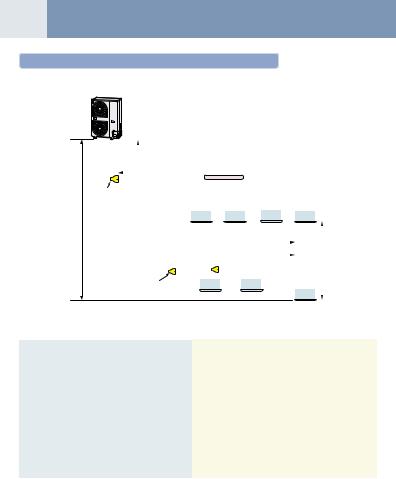
01 Refrigerant Piping
Allowable length/height difference of refrigerant piping
Outdoor unit
Height difference between indoor and outdoor units
H1
Main pipe |
|
|
|
|
|
|
|
|
|
|
|
|
|
|
|
|
|
|
|
|
|
|
|
|
|
|
|
|
|
|
|
|
|
|
|
|
|
|
|
|
|
|
|
|
|
|
|
|
|
|
|
|
|
|
|||
L1 |
|
|
|
|
|
|
|
|
|
|
|
|
|
|
|
|
|
|
|
|
|
|
|
|
|
|
||
|
|
|
|
|
Branching pipe L2 |
|
Branch header |
|
|
|
|
|
|
|
|
|
|
|
|
|
||||||||
|
|
|
|
|
|
|
|
|
|
|
|
|
|
|
|
|
|
|
|
|
|
|
|
|
|
|
|
|
1st branching |
|
|
|
|
|
|
|
a |
|
b |
|
c |
d |
|
|
|
|
|
|
|
|
|
|
|
|
|
||
section |
|
|
|
|
|
|
|
|
|
|
|
|
|
|
|
|
|
|
|
|
|
|
|
|
|
|
||
Branching pipe |
|
|
|
|
|
|
|
|
|
|
|
|
|
|
|
|
|
|
|
|
|
|
|
|
|
|
||
|
|
|
|
|
|
|
|
|
|
|
|
|
|
|
|
|
|
|
|
|
|
|
|
|
|
|||
|
|
|
|
|
|
|
|
|
|
|
|
|
|
|
|
|
|
|
|
|
|
|
|
|
||||
L3 |
|
|
|
|
|
|
|
|
|
|
|
|
|
Indoor unit |
|
|
|
|
|
|||||||||
|
|
|
|
|
Equivalent length corresponded to farthest piping L |
|
|
|
|
|
|
|||||||||||||||||
|
|
|
|
Equivalent length corresponded to farthest piping after 1st branching Li |
|
|
|
Height difference |
||||||||||||||||||||
|
|
|
|
|
|
|
|
|
|
|
|
|
|
|
|
|
|
|
|
|
|
|
|
|
|
|
between indoor units |
|
|
|
|
|
|
|
|
|
|
L4 |
|
|
|
|
|
|
|
|
|
|
|
H2 |
|||||||
|
|
|
|
|
|
|
|
|
|
|
|
|
|
|
|
|
|
|
|
|
|
|||||||
|
|
|
|
|
|
|
|
|
|
|
|
|
|
|
|
|
|
|
g |
|
|
|
|
|
|
|||
|
|
|
|
|
|
|
e |
|
|
|
|
f |
|
|
|
|
|
|
|
|
|
|
|
|
|
|
||
|
|
|
|
Y-shape |
|
|
|
|
|
|
|
|
|
|
|
|
|
|
|
|
|
|
|
|
||||
|
|
|
|
branch joint |
|
|
|
|
|
|
|
|
|
|
|
|
|
|
|
|
|
|
|
|
||||
|
|
|
|
|
|
|
|
|
|
|
|
|
|
|
|
|
|
|
|
|
|
|
|
A 1 |
|
|
|
|
|
|
|
|
|
|
|
|
|
|
|
|
|
|
|
|
|
|
|
|
|
|
|
|
|||||
|
|
|
|
|
|
|
|
|
|
|
|
|
|
|
|
|
|
|
|
|
|
|
|
|||||
|
|
|
|
|
|
|
|
|
|
|
|
|
|
|
|
|
|
|
|
|
|
|
|
|
|
|
|
|
|
|
|
Allowable value |
Piping section |
|
|
|
|
|
|
Total extension of pipe (Liquid pipe, real length) |
180 m |
L1 + L2 + L3 + L4 + a + b + c + d + e + f + g |
|
|
|
|
|
|
|
Furthest piping length |
Real length |
100 m |
L1 + L3 + L4 + g |
|
|
|
|
|
|
L (*1) |
Equivalent length |
125 m |
|
Piping |
|
|
||
|
|
|
|
|
Length |
Max. equivalent length of main pipe |
65 m |
L1 |
|
|
|
|
|
|
|
Equivalent length of furthest piping from |
35 m |
L3 + L4 + g |
|
|
1st branching Li (*1) |
|
||
|
Max. real length of indoor unit connecting pipe |
15 m |
a, b, c, d, e, f. g |
|
|
|
|
|
|
|
Height between indoor |
Upper outdoor unit |
30 m |
——— |
|
|
|
|
|
Height |
and outdoor units H1 |
Lower outdoor unit |
20 m |
——— |
Difference |
|
|||
|
|
|
|
|
|
Height between indoor units H2 |
15 m |
——— |
|
|
|
|
|
|
*1 : Furthest indoor unit from 1st branch to be named “A”.
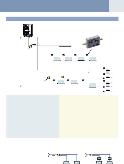
02
Allowable length/height difference of refrigerant piping for quiet places (with PMV Kit)
Outdoor unit
Main pipe |
|
L1 |
|
Branching pipe L2 |
Branch header |
|
|
|
|
|
|
|
|
|
|
|
|
|
a |
|
b |
|
c |
|
d |
|
|
|
|
|
|
|
|
|
|
PMV Kit |
|||||||
|
|
1st branching |
|
|
|
|
|
|
|
|
|
|
|
|
|
|
|
|
|
|
|
|
|
||||||||||||||
|
|
|
|
|
|
|
|
|
|
|
|
|
|
|
|
|
|
|
|
|
|
|
|
|
|
|
|
|
|
|
|
|
|||||
|
|
section |
|
|
|
|
|
|
|
|
|
|
|
|
|
|
|
|
|
|
|
|
|
|
|
|
|
|
Height difference |
||||||||
Height difference |
|
|
|
|
|
|
h |
|
|
|
|
|
|
i |
|
|
|
|
|
j |
|
|
|
|
k |
|
|
|
|
|
|
||||||
|
|
|
|
|
|
|
|
|
|
|
|
|
|
|
|
|
|
|
|
|
|
|
|
|
|
|
|||||||||||
|
|
|
|
|
|
|
|
|
|
|
|
|
|
|
|
|
|
|
|
||||||||||||||||||
|
|
|
|
|
|
|
|
|
|
|
|
|
|
|
|
|
|
|
|
|
|
|
|
|
|
|
|
|
|
|
between indoor unit |
||||||
between indoor |
Branching pipe |
|
|
|
|
|
|
|
|
|
|
|
|
|
|
|
|
|
|
|
|
|
|
|
|
|
|
|
|
|
and PMV Kit |
||||||
and outdoor units |
|
|
|
|
|
|
|
|
|
|
|
|
|
|
|
|
|
|
|
|
|
|
|
|
|
|
H2 |
||||||||||
H1 |
L3 |
|
|
|
|
|
|
|
|
|
|
|
|
|
Indoor unit |
|
|
|
|
|
|
|
|
|
* Between highest unit |
||||||||||||
|
|
|
|
|
|
|
|
|
|
|
|
|
|
|
|
|
|
|
|
|
|
|
|
|
|
|
|
|
|
|
|
|
|||||
|
|
|
|
|
|
|
|
|
|
|
|
|
|
|
|
|
|
|
|
|
|
|
|
|
|
|
|
|
|
|
|
|
and lower units. |
||||
|
|
|
|
|
|
|
|
|
|
|
|
|
|
|
|
|
|
|
|
|
|
|
|
|
|
|
|
|
|
|
|
|
Example) |
||||
|
|
|
|
|
|
Equivalent length corresponded to farthest piping L |
|
|
|
|
|
|
|
|
|
|
|
|
|
H2 |
|||||||||||||||||
|
|
|
|
|
|
|
|
|
|
|
|
|
|
|
|
|
|
|
|||||||||||||||||||
|
|
|
|
|
Equivalent length corresponded to farthest piping after 1st branching Li |
|
|
|
|
|
|
|
|
|
|||||||||||||||||||||||
|
|
|
|
|
|
|
|
|
|
L4 |
|
|
|
|
|
|
|
|
|
|
|
|
|
|
|
|
|
|
|
|
|
|
|
|
|||
|
|
|
|
|
|
|
|
|
|
|
|
|
|
|
|
|
|
|
|
|
|
|
|
|
|
|
|
|
|
|
|
|
|
||||
|
|
|
|
|
Y-shape |
|
e |
|
|
|
|
|
|
f |
|
|
|
|
|
|
g |
|
|
|
|
|
|
|
|
|
|
|
|
H2 |
|||
|
|
|
|
|
|
|
|
|
|
|
|
|
|
|
|
|
n |
|
|
|
|
|
|
|
|
|
|
|
|
||||||||
|
|
|
|
|
branch joint |
|
|
|
l |
|
|
|
|
|
|
|
m |
|
|
|
|
|
|
|
|
|
|
|
|
|
|
|
|
||||
|
|
|
|
|
|
|
|
|
|
|
|
|
|
|
|
|
|
|
|
|
|
|
|
|
|
|
|
|
A 1 |
|
|
|
|
|
|
H2 |
|
|
|
|
|
|
|
|
|
|
|
|
|
|
|
|
|
|
|
|
|
|
|
|
|
|
|
|
|
|
|
|
|
|
|
|
|
|
|
|
|
|
|
|
|
|
|
|
|
|
|
|
|
|
|
|
|
|
|
|
|
|
|
|
|
|
|
|
|
|
|
|
|
|
|
|
|
|
|
|
Allowable |
Piping section |
|
|
|
|
value |
|
|
|
Total extension of pipe |
|
150 m |
L1 + L2 + L3 + L4 |
|
|
(Liquid pipe, real length) |
|
+ a + b + c + d + e + f + g + h + I + j + k+ l + m + n |
||
|
|
|
|||
|
Furthest piping length |
Real length |
65 m |
L1 + L3 + L4 + g + n |
|
|
L (*1) |
Equivalent length |
80 m |
||
|
|
||||
|
|
|
|||
Piping |
Max. equivalent length of main pipe |
50 m |
L1 |
||
Length |
Equivalent length of furthest piping from |
15 m |
L3 + L4 + g + n |
||
|
|||||
|
1st branching Li (*1) |
|
|||
|
Max. real length of indoor unit connecting pipe |
15 m |
a + h, b + i, c + j, d + k, e + l, f + m. g + n |
||
|
Real length between PMV KIT and indoor unit |
2 m or more |
h, i, j, k, l, m, n |
||
|
below 10 m |
||||
|
|
|
|
||
Height |
Height between indoor |
Upper outdoor unit |
30 m |
——— |
|
and outdoor units H1 |
Lower outdoor unit |
20 m |
——— |
||
Difference |
|
||||
Height between indoor unit and PMV kit H2 |
15 m |
——— |
|||
|
|||||
*1 : Furthest indoor unit from 1st branch to be named “A”.
Note)
Do not connect two or more indoor units to one PMV Kit. Arrange one indoor unit and one PMV Kit set to 1 by 1.
NO GOOD OK
PMV Kit
PMV Kit
Indoor unit |
Indoor unit |
03 Continued
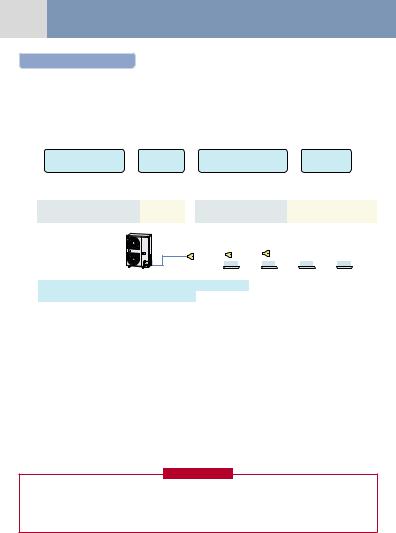
Addition of refrigerant
After vacuuming work, exchange the vacuum pump with the refrigerant bomb and then start the additional charging work of refrigerant.
Calculating the amount of additional refrigerant required
When the system is charged with refrigerant at the factory, the amount of refrigerant needed for the pipes on site is not included. Calculate the additional amount required, and add that amount to the system.
Additional refrigerant charge amount is calculated from size of liquid pipe at site and its real length.
Additional |
|
Real length |
|
Additional refrigerant charge |
|
Compensation |
|
refrigerant charge R (kg) |
= |
× |
amount per liquid pipe 1m |
+ |
by outdoor HP |
||
of liquid pipe |
|||||||
amount at site |
|
|
(Table 1) |
|
(Table 2) |
||
|
|
|
|
||||
|
|
|
|
|
|
|
Table 1
Pipe dia. at liquid side |
Ø6.4 |
Ø9.5 |
|
|
|
Additional refrigerant amount/1m (kg) |
0.025 |
0.055 |
|
|
|
Example : (0501 type)
L1
Table 2
|
Outdoor unit capacity type |
|
0401 type |
0501 type |
0601 type |
||||||||||||||
|
|
|
|
|
|
|
|||||||||||||
|
Compensation by outdoor HP (kg) |
|
–0.8 |
|
–0.4 |
0 |
|||||||||||||
|
|
|
|
|
|
|
|
|
|
|
|
|
|
|
|
|
|
||
|
L2 |
|
|
|
|
L3 |
|
|
|
|
|
|
|
|
|
|
|
||
|
|
|
|
|
|
|
|
|
|
|
|
|
|
|
|
|
|
|
|
|
a |
|
|
|
|
b |
|
|
|
|
c |
|
|
|
d |
|
|
|
|
|
|
|
|
|
|
|
|
|
|
|
|
|
|
|
|
|
|
|
|
L1 |
Ø9.5 : 10m |
L2 |
Ø9.5 : 10m |
L3 |
Ø9.5 : 5m |
a |
Ø9.5 : 3m |
|
|
|
|
|
|
|
|
b |
Ø6.4 : 3m |
c |
Ø6.4 : 4m |
d |
Ø6.4 : 5m |
|
|
|
|
|
|
|
|
|
|
Additional charge amount R (kg)
=(Lx × 0.025kg/m) + (Ly × 0.055kg/m) + (–0.4kg)
=(12 × 0.025kg) + (28 × 0.055kg) + (–0.4kg)
=1.44kg
Lx : Real total length of liquid pipe Ø6.4 (m) Ly : Real total length of liquid pipe Ø9.5 (m)
Note)
If the additional refrigerant amount indicates a negative result from the calculation, use air conditioner without the adding of any additional refrigerant.
Charging of refrigerant
•Keeping valve of the outdoor unit closed, be sure to charge the liquid refrigerant into service port at liquid side.
•If the specified amount of refrigerant cannot be charged, open fully valves of outdoor unit at liquid and discharge/suction gas sides, operate the air conditioner in COOL mode under condition that valve at suction gas side is a little returned to close side, and then charge refrigerant into service port at suction gas side. In this time, choke the refrigerant slightly by operating valve of the bomb to charge liquid refrigerant.The liquid refrigerant may be charged suddenly, therefore be sure to charge refrigerant gradually.
•When refrigerant leaks and refrigerant shortage occurs in the system, recover the refrigerant in the system and recharge refrigerant newly up to the correct level.
REQUIREMENT
Entry of refrigerant charge amount
•Complete the refrigerant record column found on the wiring diagram, with detail of the additional refrigerant amount and name of service engineer at the time of installation.
•The total amount of refrigerant refers to the shipment charge plus any additional refrigerant at the time of installation. The refrigerant amount at shipment is indicated on the unit name plate.

Refrigerant Cycle Diagram |
04 |
Model : MCY-MAP0401/0501/0601HT, MCY-MAP0401/0501/0601HT2D
Outdoor unit
Heat exchanger
Sensor (TE) 

Strainer |
|
|
Capillary |
Solenoid valve |
4-way valve |
tube 2 |
(SV5) |
|
PMV |
|
|
|
Check valve |
|
Strainer |
|
|
|
|
Solenoid valve |
|
Check joint |
(SV2) |
|
|
|
Sensor (TL) |
|
|
High-pressure |
|
|
sensor |
|
|
|
|
Solenoid valve |
High-pressure |
(SV4) |
|
switch |
|
|
|
Muffler |
|
Sensor (TD)
Liquid tank
Strainer
Check joint
Compressor (Inverter)
Sensor (TO)
Sensor (TS)
Capillary
tube 1
Low-pressure sensor
Check joint
Accumulator
Liquid side |
Gas side |
packed valve |
ball valve |

05 Continued
Explanation of Functional Parts
Functional part name |
|
Functional outline |
Connector |
|
|
|
|
|
|
Solenoid valve |
SV2 |
1) |
Low-pressure release function |
CN312 (White) |
|
|
2) |
High-pressure release function |
|
|
|
3) |
Gas balance function during off time |
|
|
|
4) |
Hot gas bypass into accumulator |
|
|
|
|
|
|
|
SV4 |
1) |
High-pressure release function |
CN311 (Blue) |
|
|
2) |
Low-pressure release function |
|
|
|
|
|
|
|
SV5 |
1) |
Preventive function for high-pressure rising in heating operation |
CN310 (White) |
|
|
|
|
|
Capillary tube |
1 |
ID : Ø1.5, Length : 200 mm |
|
|
|
|
|
|
|
|
2 |
ID : Ø2.2, Length : 100 mm |
|
|
|
|
|
|
|
4-way valve |
|
1) |
Cooling/heating exchange |
CN317 (Blue) |
|
|
2) |
Reverse defrost |
|
|
|
|
|
|
PMV (Pulse motor valve) |
1) |
Super heat control function |
CN300 (White) |
|
|
|
2) |
Sub-cool adjustment function in cooling operation |
|
|
|
|
|
|
Temp. sensor |
TD |
1) |
Protection of compressor discharge temp. Used for release |
CN502 (White) |
|
|
|
|
|
|
TS |
1) |
Controls super heat in heating operation |
CN504 (White) |
|
|
|
|
|
|
TE |
1) |
Controls defrost in heating operation |
CN505 (Green) |
|
|
2) |
Controls outdoor fan in heating operation |
|
|
|
|
|
|
|
TL |
1) |
Detects under cool in cooling operation |
CN521 (White) |
|
|
|
|
|
|
TO |
1) |
Detects outside temperature |
CN507 (Yellow) |
|
|
|
|
|
High-pressure sensor |
1) |
Detects high-pressure and controls compressor capacity |
CN501 (Red) |
|
|
|
2) |
Detects high-pressure in cooling operation and controls the fan in low |
|
|
|
|
ambient cooling operation |
|
|
|
|
|
|
Low-pressure sensor |
1) |
Detects low-pressure in cooling operation and controls compressor capacity |
CN500 (White) |
|
|
|
2) |
Detects low-pressure in heating operation and controls the super heat |
|
|
|
|
|
|
Compressor case heater |
1) |
Prevents liquid accumulation to compressor |
CN316 (White) |
|
|
|
|
|
|
Accumulator case heater |
1) |
Prevents liquid accumulation to accumulator |
CN321 (Red) |
|
|
|
|
|
|
06
Wired |
|
|
remote |
Check code name |
|
controller |
||
|
||
display |
|
|
|
|
|
E01 |
Communication error between indoor and remote controller |
|
(Detected at remote controller side) |
||
|
||
|
|
|
E02 |
Remote controller sending error |
|
|
|
|
E03 |
Communication error between indoor and remote controller |
|
(Detected at indoor side) |
||
|
||
|
|
|
E04 |
Indoor/outdoor communication circuit error |
|
(Detected at indoor side) |
||
|
||
|
|
|
E06 |
Decreased number of indoor units |
|
|
|
|
— |
Indoor/outdoor communication circuit error |
|
(Detected at outdoor side) [E07] |
||
|
||
|
|
|
E08 |
Duplicated indoor addresses |
|
|
|
|
E09 |
Duplicated master remote controllers |
|
|
|
|
E10 |
Communication error between indoor P.C. board assembly |
|
|
|
|
E12 |
Automatic address start error |
|
|
|
|
E15 |
No corresponding indoor unit during automatic address |
|
|
|
|
E16 |
No. of connected indoor units / Capacity over |
|
|
|
|
E18 |
Communication error between indoor header and follower units |
|
|
|
|
E19 |
Outdoor unit quantity error |
|
|
|
|
E20 |
Other line unit connected during automatic address |
|
|
|
|
E23 |
Communication sending error |
|
|
|
|
E25 |
Duplicated outdoor follower address setup |
|
|
|
|
E31 |
IPDU communication error |
|
|
|
|
F01 |
Indoor TCJ sensor error |
|
|
|
|
F02 |
Indoor TC2 sensor error |
|
|
|
|
F03 |
Indoor TC1 sensor error |
|
|
|
|
F04 |
TD1 sensor error |
|
|
|
|
F06 |
TE1 sensor error |
|
|
|
|
F07 |
TL sensor error |
|
|
|
|
F08 |
TO sensor error |
|
|
|
|
F10 |
Indoor TA sensor error |
|
|
|
|
F12 |
TS1 sensor error |
|
|
|
|
F13 |
TH sensor error |
|
|
|
|
F15 |
Outdoor temp sensor miscabling (TE1, TL) |
|
|
|
|
F16 |
Outdoor pressure sensor miscabling (Pd, Ps) |
|
|
|
|
F23 |
Ps sensor error |
|
|
|
|
F24 |
Pd sensor error |
|
|
|
|
F29 |
Indoor other error |
|
|
|
|
F31 |
Outdoor EEPROM error |
|
|
|
|
H01 |
Compressor breakdown |
|
|
|
|
H02 |
Compressor error (lock) |
|
|
|
Wired
remote Check code name controller
display
H03 |
Current detection circuit system error |
|
H04 |
Compressor 1 case thermo operation |
|
|
|
|
H06 |
Low-pressure protective operation |
|
|
|
|
L03 |
Duplicated indoor center units |
|
|
|
|
L04 |
Duplicated outdoor line address |
|
|
|
|
L05 |
Duplicated indoor units with priority |
|
(Displayed on indoor unit with priority) |
||
|
||
|
|
|
L06 |
Duplicated indoor units with priority |
|
(Displayed on the unit other than indoor unit with priority) |
||
|
||
|
|
|
L07 |
Group line in individual indoor unit. |
|
|
|
|
L08 |
Indoor group / address unset |
|
|
|
|
L09 |
Indoor capacity unset |
|
|
|
|
L10 |
Outdoor capacity unset |
|
|
|
|
L20 |
Duplicated central control addresses |
|
|
|
|
L29 |
IPDU quantity error |
|
|
|
|
L30 |
Interlock in indoor unit from outside |
|
|
|
|
— |
Extended IC (Integrated Circuit) error |
|
(Detected at outdoor unit side) [L31] |
||
|
||
|
|
|
P01 |
Indoor fan motor error |
|
|
|
|
P03 |
Discharge temp TD1 error |
|
|
|
|
P04 |
Actuation of high-pressure SW |
|
|
|
|
P07 |
Heat sink overheat error |
|
|
|
|
P10 |
Indoor overflow error |
|
|
|
|
P12 |
Indoor fan motor error |
The standard ducted unit air conditioner utilizes a direct current (DC) indoor fan motor that features current limiting protection.
In the event power is not isolated prior to service, the protective control circuit will activate and stop the unit operating.
The check code “P12”will be displayed on the remote controlleronce service work has been completed, this code can be cleared by switching off then on the electrical isolation device of the indoor unit and pressing the operation stop button on the remote controller to reset the system.
P13 |
Outdoor liquid back detection error |
|
|
|
|
P15 |
Gas leak detection (TS1 condition) |
|
Gas leak detection (TD condition) |
||
|
||
|
|
|
P17 |
Discharge temp TD2 error |
|
|
|
|
P19 |
4-way valve operation error |
|
|
|
|
P20 |
High-pressure protective operation |
|
|
|
|
P22 |
Outdoor fan IPDU error |
|
|
|
|
P26 |
G-Tr short-circuit protection error |
|
|
|
|
P29 |
Compressor position detection circuit error |
|
|
|
|
P31 |
Other indoor error (Group follower unit error) |
|
|
|
07 Switch (SW08) Set Up ofThe Outdoor Unit
When using the outdoor unit under the following conditions, it is necessary to set up DIP switch on the outdoor unit interface P.C. board.
Cautions
When anyone of the following condition is applied, set up DIP switch.
1.When using PMV Kit in the Mini-SMMS system
2.When using the indoor unit under high humidity condition
[Reference]
Indoor side : 27°C dry bulb temperature 24°C wet bulb temperature Operation time 4 hours or more.
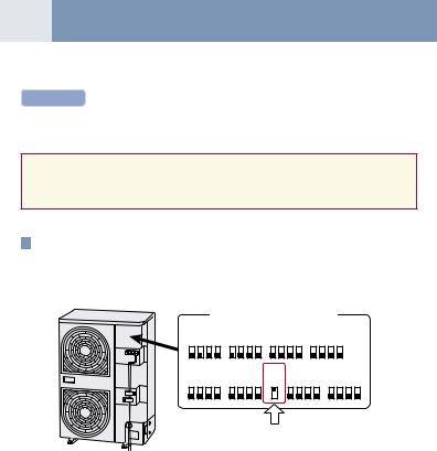
1Setup method
• Turn on DIP switch [SW08] on the interface P.C. board of the outdoor unit.
Outdoor unit interface P.C. board
|
SW11 |
|
|
SW12 |
|
SW13 |
|
|
SW14 |
|
|
|
||||||
ON |
3 |
4 |
ON |
3 |
4 |
ON |
2 |
3 |
4 |
ON |
2 |
3 |
4 |
|
|
|||
1 |
2 |
1 |
2 |
1 |
|
1 |
|
|
||||||||||
|
|
|
|
|
|
|
|
|
|
|
|
|
||||||
|
SW06 |
|
|
SW07 |
|
SW08 |
SW09 |
|
SW10 |
|
||||||||
ON |
3 |
4 |
ON |
3 |
4 |
ON |
|
ON |
2 |
3 |
4 |
|
ON |
2 |
3 |
4 |
||
1 |
2 |
1 |
2 |
1 |
|
1 |
|
1 |
||||||||||
|
|
|
|
|
|
|
|
|
|
|
|
|
|
|
|
|
|
|
Switch [SW08]
Check at Main Power-ON |
08 |
After turning on the main power of the indoor units and outdoor unit in the refrigerant line to be executed with a test operation, check the following items in outdoor and each indoor unit.
(After turning on the main power, be sure to check in order of indoor unit → outdoor unit.)
If the power supply of the outdoor unit has been firstly turned on, [E19] appears on the 7-segment display on the interface P.C. board until the power supply of the indoor unit is turned on. However it is not an error.
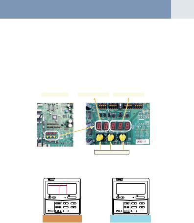
<Check on outdoor unit>
1.Check that all the rotary switches, SW01, SW02, and SW03 on the interface P.C. board of the outdoor unit are set up to “1”.
2.If other error code is displayed on 7-segment [B], remove the cause of trouble referring to “ Troubleshooting”.
3.Check that [L08] is displayed on 7-segment display [B] on the interface P.C. board of the outdoor unit. (L08: Indoor address unset up)
(If the address setup operation has already finished in service time, etc, the above check code is not displayed, and only [U1] is displayed on 7-segment display [A].)
Interface P.C. board |
|
7-segment display [A] |
|
7-segment display [B] |
SW01 SW02 SW03
<Check on indoor unit>
1.Display check on remote controller (In case of wired remote controller)
Check that a frame as shown in the following left figure is displayed on LC display section of the remote controller.
GOOD |
|
|
NO |
|
|
|
|
GOOD |
|
|
|
|
|
|
|
|
|
TEMP. |
|
ON / OFF |
TEMP. |
|
ON / OFF |
TIMER SET |
FAN |
MODE |
TIMER SET |
FAN |
MODE |
TIME |
SWING/FIX |
VENT |
TIME |
SWING/FIX |
VENT |
FILTER |
|
|
FILTER |
|
|
RESET TEST SET CL |
UNIT |
|
RESET TEST SET CL |
UNIT |
|
Normal status |
Abnormal status |
||||
(Power and operation stop) |
(Power is not normally turned on.) |
||||
If a frame is not displayed as shown in the above right figure, the power of the remote controller is not normally turned on. Therefore check the following items.
•Check power supply of indoor unit.
•Check wiring between indoor unit and remote controller.
•Check whether there is cutoff of cable around the indoor control P.C. board or not, and check connection failure of connectors.
•Check failure of transformer for the indoor microcomputer.
•Check indoor control P.C. board failure.
09 Address Setup
After power-ON, set up the indoor address from the interface P.C. board of the outdoor unit. (The address setup operation cannot be performed by power-ON only. )
Cautions
1.It requires approx. 5 minutes usually for 1 line to automatically set up address. However in some cases, it may require maximum 10 minutes.
2.It is unnecessary to operate the air conditioner for address setup.
3.Manual address setup is also available besides automatic setup.
Automatic address: Setup from SW15 on the interface P.C. board of the outdoor unit
Manual address: Setup from the wired remote controller. (For details, refer to section “Address setup procedure”)
Address Setup and Check Procedure
Procedure |
Item |
|
|
Operation and check contents |
|
|
|||||
|
|
|
|
|
|
|
|
|
|
||
1 |
Indoor unit power-ON |
Turn on power of indoor unit in refrigerant line to which address is set up. |
|
|
|||||||
|
|
|
|
|
|
|
|
|
|
||
2 |
Outdoor unit power-ON |
Turn on power of all the outdoor units in refrigerant line to which address is set up. |
|
|
|||||||
|
|
|
|
|
|
|
|
|
|||
3 |
7-segment display check |
Check that [L08] is displayed on 7-segment display [B] on the interface P.C. board of the outdoor |
|||||||||
|
unit in the system to which address is set up. |
|
|
|
|
||||||
|
|
|
|
|
|
||||||
|
|
|
|
|
|
|
|
|
|||
|
|
Confirm the corresponding items in “Address setup procedure”, and then set up address |
|||||||||
4 |
Address setup start |
according to the operation procedure. |
|
|
|
|
|
||||
(Be sure that the setup operation may differ in group control or central control.) |
|
|
|||||||||
|
|
|
|
||||||||
|
|
Note) Address cannot be set up if switches are not operated. |
|
|
|||||||
|
|
|
|
|
|
|
|
|
|
|
|
|
Display check after |
• After address setup, [U1] [ |
] are displayed in 7-segment display section. |
|
|
||||||
5 |
• If an error code is displayed in 7-segment display [B], remove the cause of trouble referring to |
||||||||||
setup |
|||||||||||
|
|
“Troubleshooting”. |
|
|
|
|
|
|
|
||
|
|
|
|
|
|
|
|
|
|||
|
|
Using 7-segment display function, check the system information of the scheduled system. |
|||||||||
|
|
(This check is executed on the interface P.C. board of the outdoor unit.) |
|
|
|||||||
|
|
|
|
|
|
|
|
|
|
|
|
|
|
|
|
|
Rotary switch setup |
7-segment display |
|
|
|||
|
|
|
|
|
|
|
|
|
|
|
|
|
System information |
|
|
|
SW01 |
SW02 |
SW03 |
[A] |
[B] |
|
|
6 |
|
|
|
|
|
|
|
|
|
||
check after setup |
|
System capacity |
|
1 |
2 |
3 |
[No. of HP] |
[HP] |
|
||
|
|
|
|
|
|
|
|
|
|
||
|
|
|
No. of connected outdoor unit |
|
1 |
3 |
3 |
[Connected No. of units] |
[ P] |
|
|
|
|
|
|
|
|
|
|
|
|
|
|
|
|
|
No. of connected indoor units |
|
1 |
4 |
3 |
[Connected No. of units] |
|
|
|
|
|
|
|
|
|
|
|
|
|
||
|
|
After the above checks, return rotary switches SW01, SW02, SW03 to 1/1/1. |
|
|
|||||||
|
|
|
|
|
|
|
|
|
|
|
|
|
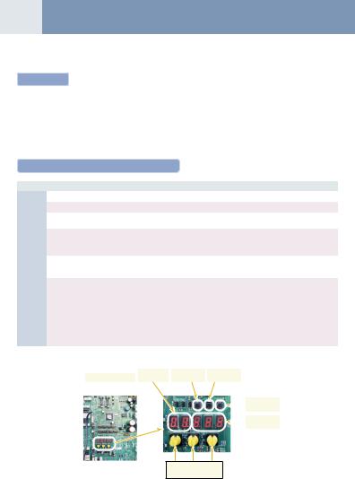
|
7-segment |
|
Push-switch |
Push-switch |
|
|
|
Interface P.C. board |
|
display [A] |
|
SW04 |
SW05 |
|
|
|
|
|
|
|
|
|
|
|
|
|
|
|
|
|
|
|
|
Push-switch |
|
|
|
|
|
|
|
|
SW15 |
|
|
|
|
|
|
|
|
|
|
|
|
|
|
|
|
|
7-segment |
|
|
|
|
|
|
|
|
display [B] |
SW01 SW02 SW03
Rotary switches
 Loading...