


MMU-AP0182H2UL
Toshiba MMU-AP0182H2UL, MMU-AP0152H2UL, MMU-AP0122H2UL, MMU-AP0212H2UL, MMU-AP0242H2UL Service Manual
...
R410A
4-Way Cassette Type
Compact 4-Way Cassette Type
Ceiling Type
High Wall Type
SERVICE MANUAL
AIR-CONDITIONER
MULTI TYPE
INDOOR UNIT
4-Way Cassette Type
MMU-AP0072H2UL-1
MMU-AP0072H2UL, MMU-AP0092H2UL,
MMU-AP0122H2UL, MMU-AP0152H2UL,
MMU-AP0182H2UL, MMU-AP0212H2UL,
MMU-AP0242H2UL, MMU-AP0302H2UL,
MMU-AP0362H2UL, MMU-AP0422H2UL
Compact 4-Way Cassette Type
MMU-AP0071MH2UL, MMU-AP0091MH2UL,
MMU-AP0121MH2UL, MMU-AP0151MH2UL,
MMU-AP0181MH2UL
Ceiling Type
MMC-AP0181H2UL, MMC-AP0241H2UL,
MMC-AP0361H2UL, MMC-AP0421H2UL
High Wall Type
MMK-AP0073H2UL, MMK-AP0093H2UL,
MMK-AP0123H2UL, MMK-AP0153H2UL,
MMK-AP0183H2UL, MMK-AP0243H2UL
PRINTED IN JAPAN, Mar., 2011 ToMo
FILE NO. A10-019
Revision 1 : Feb., 2013
Revision 2 : Sep., 2014
Revision 3 : Oct., 2014
Revision 4 : Jun., 2015
Revision 5 : Apr., 2016
Revision 6 : Jun., 2017

2
CONTENTS
SAFETY CAUTION .............................................................................3
1. SPECIFICATIONS ....................................................................... 8
2. CONSTRUCTION VIEWS (EXTERNAL VIEWS) .......................11
3. WIRING DIAGRAM ................................................................... 23
4. PARTS RATING......................................................................... 27
5. REFRIGERATIN GCYCLE DIAGRAM ...................................... 29
6. CONTROL OUTLINE ................................................................ 30
7. APPLIED CONTROL AND FUNCTION .................................... 46
8. TROUBLESHOOTING............................................................... 77
9. DETACHMENTS........................................................................ 99
10. P.C. BOARD EXCHANGE PROCEDURES ............................. 138
11. EXPLODED VIEWS AND PARTS LIST ................................... 148
3
SAFETY CAUTION
The important contents concerned to the safety are described on the product itself and on this Service Manual.
Please read this Service Manual after understanding the described items thoroughly in the following contents
(Indications/Illustrated marks), and keep them. The manufacturer shall not assume any liability for the damage
caused by not observing the description of this manual.
[Explanation of indications]
∗ Property damage : Enlarged damage concerned to property, furniture, and domestic animal/pet
[Explanation of illustrated marks]
[Confirmation of warning label on the main unit]
Confirm that labels are indicated on the specified positions
(Refer to the Parts disassembly diagram (Outdoor unit).)
If removing the label during parts replace, stick it as the original.
Indication
DANGER
WARNING
CAUTION
Explanation
Indicates contents assumed that an imminent danger causing a death or serious injury of
the repair engineers and the third parties when an incorrect work has been executed.
Indicates possibilities assumed that a danger causing a death or serious injury of the
repair engineers, the third parties, and the users due to troubles of the product after work
when an incorrect work has been executed.
Indicates contents assumed that an injury or property damage (∗) may be caused on the
repair engineers, the third parties, and the users due to troubles of the product after work
when an incorrect work has been executed.
Mark Explanation
Indicates prohibited items (Forbidden items to do)
The sentences near an illustrated mark describe the concrete prohibited contents.
Indicates mandatory items (Compulsory items to do)
The sentences near an illustrated mark describe the concrete mandatory contents.
Indicates cautions (Including danger/warning)
The sentences or illustration near or in an illustrated mark describe the concrete cautious contents.
Turn off breaker.
Execute discharge
between terminals.
Prohibition
Turn “OFF” the breaker before removing the front panel and cabinet, otherwise an electric
shock is caused by high voltage resulted in a death or injury.
During operation, a high voltage with 400V or higher of circuit (∗) at secondary circuit of the
high-voltage transformer is applied.
If touching a high voltage with the naked hands or body, an electric shock is caused even if using an
electric insulator.
∗ :# For details, refer to the electric wiring diagram.
When removing the front panel or cabinet, execute short-circuit and discharge between
high-voltage capacitor terminals.
If discharge is not executed, an electric shock is caused by high voltage resulted in a death or injury.
After turning off the breaker, high voltage also keeps to apply to the high-voltage capacitor.
Do not turn on the breaker under condition that the front panel and cabinet are removed.
An electric shock is caused by high voltage resulted in a death or injury.
DANGER

4
Check ground wires.
Prohibition of modification.
Use specified parts.
Do not bring a child
close to the equipment.
Insulating measures
No fire
Refrigerant
Assembly/Cabling
Before troubleshooting or repair work, check the ground wire is connected to the ground
terminals of the main unit, otherwise an electric shock is caused when a leak occurs.
If the ground wire is not correctly connected, contact an electric engineer for rework.
Do not modify the products.
Do not also disassemble or modify the parts. It may cause a fire, electric shock or injury.
For spare parts, use those specified (
∗∗
∗∗
∗).
If unspecified parts are used, a fire or electric shock may be caused.
∗: For details, refer to the parts list.
Before troubleshooting or repair work, do not bring a third party (a child, etc.) except
the repair engineers close to the equipment.
It causes an injury with tools or disassembled parts.
Please inform the users so that the third party (a child, etc.) does not approach the equipment.
Connect the cut-off lead wires with crimp contact, etc, put the closed end side upward
and then apply a water-cut method, otherwise a leak or production of fire is caused at
the users’ side.
When repairing the refrigerating cycle, take the following measures.
1) Be attentive to fire around the cycle. When using a gas stove, etc, be sure to put out fire
before work; otherwise the oil mixed with refrigerant gas may catch fire.
2) Do not use a welder in the closed room.
When using it without ventilation, carbon monoxide poisoning may be caused.
3) Do not bring inflammables close to the refrigerant cycle, otherwise fire of the welder may
catch the inflammables.
Check the used refrigerant name and use tools and materials of the parts which match with it.
For the products which use R410A refrigerant, the refrigerant name is indicated at a position
on the outdoor unit where is easy to see. To prevent miss-charging, the route of the service
port is changed from one of the former R22.
Do not useany refrigerant different from the onespecified for complement or replacement.
Otherwise, abnormally high pressuremay be generated in the refrigeration cycle, which may
result in a failure or explosion of the product or an injury to your body.
For an air conditioner which uses R410A, never use other refrigerant than R410A.
For an air conditioner which uses other refrigerant (R22, etc.), never use R410A.
If different types of refrigerant are mixed, abnormal high pressure generates in the
refrigerating cycle and an injury due to breakage may be caused.
Do not charge refrigerant additionally.
If charging refrigerant additionally when refrigerant gas leaks, the refrigerant composition in
the refrigerating cycle changes resulted in change of air conditioner characteristics or
refrigerant over the specified standard amount is charged and an abnormal high pressure is
applied to the inside of the refrigerating cycle resulted in cause of breakage or injury. Therefore
if the refrigerant gas leaks, recover the refrigerant in the air conditioner, execute vacuuming,
and then newly recharge the specified amount of liquid refrigerant.
In this time, never charge the refrigerant over the specified amount.
When recharging the refrigerant in the refrigerating cycle, do not mix the refrigerant or
air other than R410A into the specified refrigerant.
If air or others is mixed with the refrigerant, abnormal high pressure generates in the
refrigerating cycle resulted in cause of injury due to breakage.
After installation work, check the refrigerant gas does not leak.
If the refrigerant gas leaks in the room, poisonous gas generates when gas touches to fire
such as fan heater, stove or cocking stove though the refrigerant gas itself is innocuous.
Never recover the refrigerant into the outdoor unit.
When the equipment is moved or repaired, be sure to recover the refrigerant with recovering
device. The refrigerant cannot be recovered in the outdoor unit; otherwise a serious accident
such as breakage or injury is caused.
After repair work, surely assemble the disassembled parts, and connect and lead the
removed wires as before. Perform the work so that the cabinet or panel does not catch
the inner wires.
If incorrect assembly or incorrect wire connection was done, a disaster such as a leak or fire is
caused at user’s side.
WARNING

5
After the work has finished, be sure to use an insulation tester set (500V Megger) to
check the resistance is 2MΩ or more between the charge section and the non-charge
metal section (Ground position).
If the resistance value is low, a disaster such as a leak or electric shock is caused at user’s
side.
When the refrigerant gas leaks during work, execute ventilation.
If the refrigerant gas touches to a fire, poisonous gas generates.
A case of leakage of the refrigerant and the closed room full with gas is dangerous because
a shortage of oxygen occurs. Be sure to execute ventilation.
When checking the circuit inevitably under condition of the power-ON, use rubber
gloves and others not to touch to the charging section.
If touching to the charging section, an electric shock may be caused.
When the refrigerant gas leaks, find up the leaked position and repair it surely.
If the leaked position cannot be found up and the repair work is interrupted, pump-down
and tighten the service valve, otherwise the refrigerant gas may leak into the room.
The poisonous gas generates when gas touches to fire such as fan heater, stove or cocking
stove though the refrigerant gas itself is innocuous.
When installing equipment which includes a large amount of charged refrigerant
such as a multi air conditioner in a sub-room, it is necessary that the density does
not the limit even if the refrigerant leaks.
If the refrigerant leaks and exceeds the limit density, an accident of shortage of oxygen is
caused.
For the installation/moving/reinstallation work, follow to the Installation Manual.
If an incorrect installation is done, a trouble of the refrigerating cycle, water leak, electric
shock or fire is caused.
After repair work has finished, check there is no trouble.
If check is not executed, a fire, electric shock or injury may be caused.
For a check, turn off the power breaker.
After repair work (installation of front panel and cabinet) has finished, execute a test
run to check there is no generation of smoke or abnormal sound.
If check is not executed, a fire or an electric shock is caused.
Before test run, install the front panel and cabinet.
Check the following items after reinstallation.
1) The ground wire is correctly connected.
2) The power cord is not caught in the product.
3) There is no inclination or unsteadiness and the installation is stable.
If check is not executed, a fire, an electric shock or an injury is caused.
Insulator check
Ventilation
Be attentive to
electric shock
Compulsion
Check after repair
Check after reinstallation
WARNING
Put on gloves
Cooling check
Be sure to put on the gloves (∗) and a long sleeved shirt:
otherwise an injury may be caused with the parts, etc.
(∗) Heavy gloves such as work gloves
When the power was turned on, start to work after the equipment has been
sufficiently cooled.
As temperature of the compressor pipes and others became high due to cooling/heating
operation, a burn may be caused.
CAUTION

6
• New Refrigerant (R410A)
This air conditioner adopts a new HFC type refrigerant (R410A) which does not deplete the ozone layer.
1. Safety Caution Concerned to New Refrigerant
The pressure of R410A is high 1.6 times of that of the former refrigerant (R22).
Accompanied with change of refrigerant, the refrigerating oil has been also changed.
Therefore, be sure that water, dust, the former refrigerant or the former refrigerating oil is not mixed into the
refrigerating cycle of the air conditioner with new refrigerant during installation work or service work.
If an incorrect work or incorrect service is performed, there is a possibility to cause a serious accident.
Use the tools and materials exclusive to R410A to purpose a safe work.
2. Cautions on Installation/Service
1) Do not mix the other refrigerant or refrigerating oil.
For the tools exclusive to R410A, shapes of all the joints including the service port differ from those of
the former refrigerant in order to prevent mixture of them.
2) As the use pressure of the new refrigerant is high, use material thickness of the pipe and tools which are
specified for R410A.
3) In the installation time, use clean pipe materials and work with great attention so that water and others
do not mix in because pipes are affected by impurities such as water, oxide scales, oil, etc.
Use the clean pipes.
Be sure to brazing with flowing nitrogen gas. (Never use gas other than nitrogen gas.)
4) For the ground protection, use a vacuum pump for air purge.
5) R410A refrigerant is azeotropic mixture type refrigerant.
Therefore use liquid type to charge the refrigerant. (If using gas for charging, composition of the
refrigerant changes and then characteristics of the air conditioner change.)
3. Pipe Materials
For the refrigerant pipes, copper pipe and joints are mainly used.
It is necessary to select the most appropriate pipes to conform to the standard.
Use clean material in which impurities adhere inside of pipe or joint to a minimum.
1) Copper pipe
<Piping>
The pipe thickness, flare finishing size, flare nut and others differ according to a refrigerant type.
When using a long copper pipe for R410A, it is recommended to select “Copper or copper-base pipe
without seam” and one with bonded oil amount 0.0001 lbs / 32’ 10” (40mg / 10m) or less.
Also do not use crushed, deformed, discolored (especially inside) pipes.
(Impurities cause clogging of expansion valves and capillary tubes.)
<Flare nut>
Use the flare nuts which are attached to the air conditioner unit.
2) Joint
The flare joint and socket joint are used for joints of the copper pipe.
The joints are rarely used for installation of the air conditioner. However clear impurities when using them.

7
4. Tools
1. Required Tools for R410A
Mixing of different types of oil may cause a trouble such as generation of sludge, clogging of capillary,
etc. Accordingly, the tools to be used are classified into the following three types.
1) Tools exclusive for R410A (Those which cannot be used for conventional refrigerant (R22))
2) Tools exclusive for R410A, but can be also used for conventional refrigerant (R22)
3) Tools commonly used for R410A and for conventional refrigerant (R22)
The table below shows the tools exclusive for R410A and their interchangeability.
Tools exclusive for R410A (The following tools for R410A are required.)
Tools whose specifications are changed for R410A and their interchangeability
(Note) When flaring is carried out for R410A using the conventional flare tools, adjustment of projection
margin is necessary. For this adjustment, a copper pipe gauge, etc. are necessary.
General tools (Conventional tools can be used.)
In addition to the above exclusive tools, the following equipments which serve also for R22 are necessary
as the general tools.
1) Vacuum pump. Use vacuum pump by
attaching vacuum pump adapter. 7) Screwdriver (+, –)
2) Torque wrench 8) Spanner or Monkey wrench
3) Pipe cutter 9) Hole core drill
4) Reamer 10) Hexagon wrench (Opposite side 4mm)
5) Pipe bender 11) Tape measure
6) Level vial 12) Metal saw
Also prepare the following equipments for other installation method and run check.
1) Clamp meter 3) Insulation resistance tester (Megger)
2) Thermometer 4) Electroscope
No.
c
d
e
f
g
h
i
j
k
Used tool
Flare tool
Copper pipe gauge for
adjusting projection margin
Torque wrench
Gauge manifold
Charge hose
Vacuum pump adapter
Electronic balance for
refrigerant charging
Refrigerant cylinder
Leakage detector
Usage
Pipe flaring
Flaring by conventional
flare tool
Tightening of flare nut
Evacuating, refrigerant
charge, run check, etc.
Vacuum evacuating
Refrigerant charge
Refrigerant charge
Gas leakage check
R410A
air conditioner installation
Existence of Whether conven-
new equipment tional equipment
for R410A can be used
Yes *(Note)
Yes *(Note)
Ye s N o
Ye s N o
Ye s N o
Ye s Ye s
Ye s N o
Ye s N o
Conventional air
conditioner installation
Whether conventional
equipment can be used
Ye s
*(Note)
No
No
Ye s
Ye s
No
Ye s
8
1. SPECIFICATIONS
1-1. 4-Way Cassette Type
Model name MMU-
Cooling Capacity kBtu/h
Heating Capacity kBtu/h
Electrical
Power supply
characteristics
Power consumption kW
Appearance (Celling panel)* Model
Height In
Unit Width In
Dimension
Depth In
(Celling panel)*
Height In
Packing Width In
Depth In
Total Weight
Unit Ibs
(Celling panel)*
Packed unit Ibs
Standard air flow
cfm
Fan unit (High/Mid/Low)
Motor output W
Gas side In
Connection Liquid side In
pipe
drain port
In
(nominal dia.)
Sound pressure level (High/Mid/Low) (*1)
AP0212H2ULAP0182H2ULAP0152H2UL AP0242H2UL AP0302H2UL AP0362H2UL AP0422H2UL
18 21 24 30 36 42
20 24 27 34 40 47.5
230 V (208/230V) 1 phase 60Hz
0.026 0.036 0.036 0.043 0.088 0.112
RBC-U31PG(W)-UL*
10.1 (1.2)* 10.1 (1.2)* 10.1 (1.2)* 10.1 (1.2)* 12.6 (1.2)* 12.6 (1.2)*
33.1 (37.4)* 33.1 (37.4)* 33.1 (37.4)* 33.1 (37.4)* 33.1 (37.4)* 33.1 (37.4)*
33.1 (37.4)* 33.1 (37.4)* 33.1 (37.4)* 33.1 (37.4)* 33.1 (37.4)* 33.1 (37.4)*
11.3 (3.9)* 11.3 (3.9)* 11.3 (3.9)* 13.8 (3.9)* 13.8 (3.9)* 13.8 (3.9)*
36.0 (39.8)* 36.0 (39.8)* 36.0 (39.8)* 36.0 (39.8)* 36.0 (39.8)* 36.0 (39.8)*
37.2 (39.8)* 37.2 (39.8)* 37.2 (39.8)* 37.2 (39.8)* 37.2 (39.8)* 37.2 (39.8)*
46 (10)* 48 (10)* 48 (10)* 48 (10)* 59 (10)* 59 (10)*
55 (15.5)* 57 (15.5)* 57 (15.5)* 57 (15.5)* 69 (15.5)* 69 (15.5)*
550/480/440 670/540/490 670/540/490 730/630/510
1,160/840/630 1,250/840/670
60 60 60 60 150 150
1/2” 5/8” 5/8” 5/8” 5/8” 5/8”
1/4” 3/8” 3/8” 3/8” 3/8” 3/8”
VP25 (Polyvinyl chloride tube : Extermal Dia. 1-1/4 Internal Dia.1)
35/33/31
15.4
17
0.026
10.1 (1.2)*
33.1 (37.4)*
33.1 (37.4)*
11.3 (3.9)*
36.0 (39.8)*
37.2 (39.8)*
46 (10)*
55 (15.5)*
550/480/440
60
1/2”
1/4”
35/33/31 38/33/31 38/33/31 41/36.5/34 46/40.5/36.5
48.5/40.5/37.5
* Figuresin parentheses are for ceiling panels.
(*1) The actual values in an external opeating environment are generally higher than the indicated values due to
the contribution from ambient noise.
* Figuresin parentheses are for ceiling panels.
(*1) The actual values in an external opeating environment are generally higher than the indicated values due to
the contribution from ambient noise.
• About the connection of MMU-AP0072H2UL-1, please refer to DATA BOOK of SMMS-e UL
Model name MMU-
Cooling Capacity kBtu/h
Heating Capacity kBtu/h
Electrical
Power supply
characteristics
Power consumption kW
Appearance (Celling panel)* Model
Height In
Unit Width In
Dimension
Depth In
(Celling panel)*
Height In
Packing Width In
Depth In
Total Weight
Unit Ibs
(Celling panel)*
Packed unit Ibs
Standard air flow
cfm
Fan unit (High/Mid/Low)
Motor output W
Gas side In
Connection Liquid side In
pipe
Drain port
In
(nominal dia.)
Sound pressure level (High/Mid/Low) (*1)
AP0122H2ULAP0092H2ULAP0072H2UL
9.5 12.0
10.5 13.5
230 V (208/230V) 1 phase 60Hz
0.021 0.023
RBC-U31PG(W)-UL*
10.1 (1.2)*
33.1 (37.4)*
33.1 (37.4)*
11.3 (3.9)*
36.0 (39.8)*
37.2 (39.8)*
42 (10)*
51 (15.5)*
10.1 (1.2)*
33.1 (37.4)*
33.1 (37.4)*
11.3 (3.9)*
36.0 (39.8)*
37.2 (39.8)*
42 (10)*
51 (15.5)*
470/430/400 550/490/460
60
3/8"
1/4"
60
3/8"
1/4"
VP25 (Polyvinyl chloride tube : Extermal Dia. 1-1/4 Internal Dia.1)
32.5/30.5/29
7.5
8.5
0.021
10.1 (1.2)*
33.1 (37.4)*
33.1 (37.4)*
11.3 (3.9)*
36.0 (39.8)*
37.2 (39.8)*
42 (10)*
51 (15.5)*
470/430/400
60
3/8"
1/4"
32.5/30.5/29
AP0072H2UL-1
7.5
8.5
0.023
10.1 (1.2)*
33.1 (37.4)*
33.1 (37.4)*
11.3 (3.9)*
36.0 (39.8)*
37.2 (39.8)*
42 (10)*
51 (15.5)*
550/490/460
60
3/8"
1/4"
34/31.5/29.5 34/31.5/29.5

9
1-3. Ceiling Type
(*1) The actual values in an external opeating environment are generally higher than the indicated values due to
the contribution from ambient noise.
Model name MMC-
Cooling Capacity kBtu/h
Heating Capacity kBtu/h
Electrical
Power supply
characteristics
Power consumption kW
Height In
Unit Width In
Dimension
Depth In
Height In
Packing Width In
Depth In
Total Weight
Unit Ibs
Packed unit Ibs
Standard air flow
cfm
Fan unit (High/Mid/Low)
Motor output W
Gas side In
Connection Liquid side In
pipe
Drain port
In
(nominal dia.)
Sound pressure level
dB (A)
(High/Mid/Low) (*1)
AP0181H2UL AP0241H2UL AP0361H2UL AP0421H2UL
18 24 36 42
20 27 40 47.5
230 V (208/230V) 1 phase 60Hz
0.038 0.05 0.091 0.11
8.3 8.3 8.3 8.3
35.8 46.5 62.8 62.8
26.8 26.8 26.8 26.8
12.4 12.4 12.4 12.4
39.1 50.0 66.1 66.1
32.0 32.0 32.0 32.0
46 57 75 75
62 75 97 97
410/360/320 590/530/470 880/770/680 950/820/730
60 60 120 120
1/2” 5/8” 5/8” 5/8”
1/4” 3/8” 3/8” 3/8”
VP20 (Polyvinyl chloride tube : Exter mal Dia. 1 Internal Dia.0.79)
38.5/35/32.5 40.5/38/35 44/41/37 46/42.5/39.5
* Figuresin parentheses are for ceiling panels.
(*1) The actual values in an external opeating environment are generally higher than the indicated values due to
the contribution from ambient noise.
1-2. Compact 4-Way Cassette Type
Model name MMU-
Cooling Capacity kBtu/h
Heating Capacity kBtu/h
Electrical
Power supply
characteristics
Power consumption kW
Appearance (Celling panel)* Model
Height In
Unit Width In
Dimension
Depth In
(Celling panel)*
Height In
Packing Width In
Depth In
Total Weight
Unit Ibs
(Celling panel)*
Packed unit Ibs
Standard air flow
cfm
Fan unit (High/Mid/Low)
Motor output W
Gas side In
Connection Liquid side In
pipe
Drain port
In
(nominal dia.)
Sound pressure level
dB (A)
(High/Mid/Low) (*1)
AP0071MH2UL AP0091MH2UL AP0121MH2UL AP0151MH2UL AP0181MH2UL
7.5 9.5 12 15.4 18
8.5 10.5 13.5 17 20
230 V (208/230V) 1 phase 60Hz
0.034 0.036 0.038 0.041 0.052
RBC-UM11PG(W)-UL*
10.6 (1.1)* 10.6 (1.1)* 10.6 (1.1)* 10.6 (1.1)* 10.6 (1.1)*
22.6 (27.6)* 22.6 (27.6)* 22.6 (27.6)* 22.6 (27.6)* 22.6 (27.6)*
22.6 (27.6)* 22.6 (27.6)* 22.6 (27.6)* 22.6 (27.6)* 22.6 (27.6)*
12.6 (3.9)* 12.6 (3.9)* 12.6 (3.9)* 12.6 (3.9)* 12.6 (3.9)*
25.2 (30.7)* 25.2 (30.7)* 25.2 (30.7)* 25.2 (30.7)* 25.2 (30.7)*
25.2 (30.7)* 25.2 (30.7)* 25.2 (30.7)* 25.2 (30.7)* 25.2 (30.7)*
35 (6.6)* 35 (6.6)* 35 (6.6)* 35 (6.6)* 35 (6.6)*
42 (13.2)* 42 (13.2)* 42 (13.2)* 42 (13.2)* 42 (13.2)*
320/270/220 330/280/220 330/300/240 390/330/280 450/380/310
60 60 60 60 60
3/8” 3/8” 3/8” 1/2” 1/2”
1/4” 1/4” 1/4” 1/4” 1/4”
VP25 (Polyvinyl chloride tube : Extermal Dia. 1-1/4 Internal Dia.1)
38.5/35/31 40/35.5/31 40/36/32 42.5/37.5/33 46.5/41.5/36

10
1-4. High Wall Type
Model name MMK-
Cooling Capacity kBtu/h
Heating Capacity kBtu/h
Electrical
Power supply
characteristics
Power consumption kW
Height In
Unit Width In
Dimension
Depth In
Height In
Packing Width In
Depth In
Total Weight
Unit Ibs
Packed unit Ibs
Standard air flow
cfm
Fan unit (High/Mid/Low)
Motor output W
Gas side In
Connection Liquid side In
pipe
drain port
In
(nominal dia.)
Sound pressure level
dB (A)
(High/Mid/Low) (*1)
AP0073H2UL AP0093H2UL AP0123H2UL AP0153H2UL AP0183H2UL AP0243H2UL
7.5 9.5 12 15.4 18 24
8.5 10.5 13.5 17 20 27
230 V (208/230V) 1 phase 60Hz
0.018 0.021 0.021 0.043 0.043 0.05
12.6 12.6 12.6 12.6 12.6 12.6
41.3 41.3 41.3 41.3 41.3 41.3
9.0 9.0 9.0 9.0 9.0 9.0
15.7 15.7 15.7 15.7 15.7 15.7
43.9 43.9 43.9 43.9 43.9 43.9
11.9 11.9 11.9 11.9 11.9 11.9
33 33 33 33 33 33
42 42 42 42 42 42
340/270/230 350/280/230 350/280/230 490/390/320 490/390/320 600/440/340
30 30 30 30 30 30
3/8” 3/8” 3/8” 1/2” 1/2” 5/8”
1/4” 1/4” 1/4” 1/4” 1/4” 3/8”
VP16 (Polyvinyl chloride tube : Extermal Dia.0.87 Internal Dia.0.63)
36/32.5/30 39/34/30 39/34/30 43/38/34.5 43/38/34.5 47.5/40.5/35
(*1) The actual values in an external opeating environment are generally higher than the indicated values due to
the contribution from ambient noise.

11
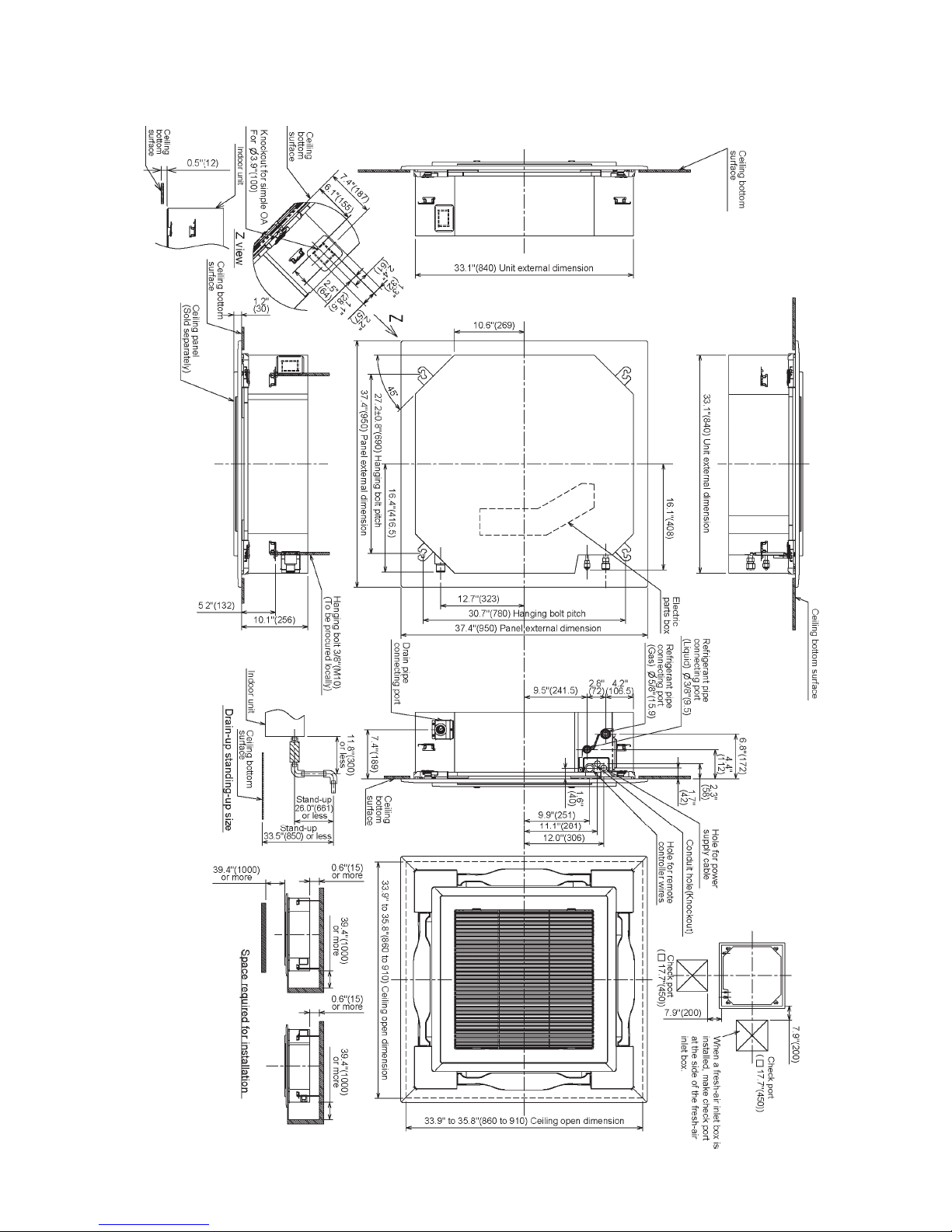
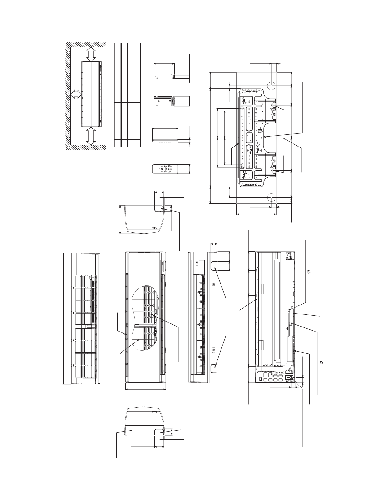
2. CONSTRUCTION VIEWS (EXTERNAL VIEWS)
2-1. 4-Way Cassette Type
MMU-AP0072H2UL-1, AP0072H2UL, AP0092H2UL, AP0122H2UL
Unit: in (mm)

12
MMU-AP0152H2UL, AP0182H2UL
Unit: in (mm)
13
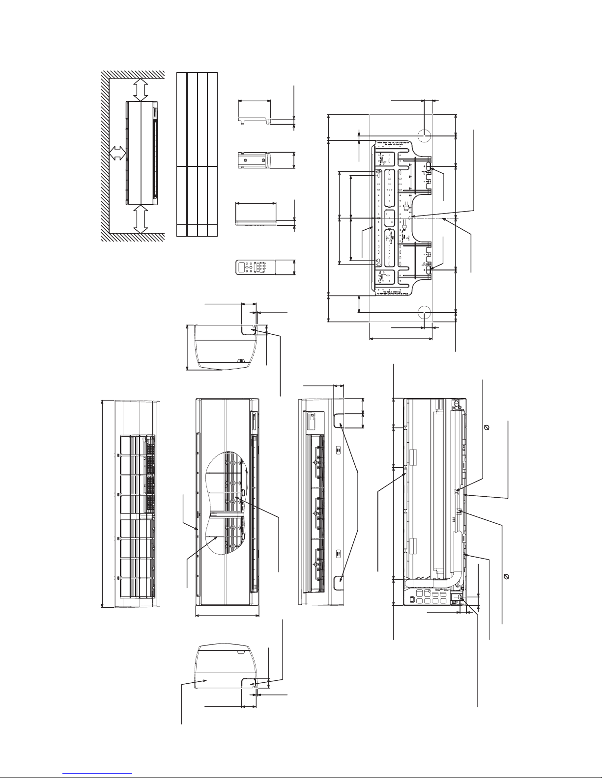
MMU-AP0212H2UL, MMU-AP0242H2UL, MMU-AP0302H2UL
Unit: in (mm)

14
MMU-AP0362H2UL, MMU-AP0422H2UL
Unit: in (mm)

15
2-2. Compact 4-Way Cassette Type
MMU-AP0071MH2UL, MMU-AP0091MH2UL, MMU-AP0121MH2UL
Unit: in (mm)

16
MMU-AP0151MH2UL, MMU-AP0181MH2UL
Unit: in (mm)

17
2-3. Ceiling Type
MMC-AP0181H2UL
Unit: in (mm)
Wireless sensor mounting section
35.8"(910)
Hanging bolt
Ceiling
Unit
surface
Within
2.0"(50)
3.0"
(75)
3.8"
(97)
5.7"
(146)
connecting port 1/4"(6.4)
(Liquid side)
Left drain size
(Hanging position)
3.3"
(84)
6.7"(170)12.6"(320)
33.7"(855)
(Hanging position)
Drain pipe
Connecting port
Upper pipe draw-out port(Knockout)
Hole for remote control wires(Knockout)
4.3"
(110)
3.0"
(76)
8.5"(216)
2.8"
(70)
2.1"
(53)
1.5"
(39)
2.0"
(52)
5.1"
(130)
2.0"
(50)
(Hole for power supply cable, knockout)
Conduit hole
Pipe draw-out port(Knockout)
8.5"(216)(Gas pipe)
4.1"
(105)
6.6"(167)
8.3"(210)
26.8"(680)
5.6"
(141)
4.5"(114)
7.9"(200)(Liquid pipe)
(Front side to be positioned horizontally.)
9.8"(250) or more 9.8"(250) or more
19.7"(500)
or more
Space required for installation and servicing
Knockout hole 3.6"(92)
Piping hole on the wall( 3.9"(100) hole)
Hole for remote control wires
Conduit hole(Hole for power supply cable)
Conduit hole(Knockout)
5.7"(145)
5.3"(135)
7.8"(197)
10.3"(262)
12.4"(316)
3.5"
(90)
1.3"
(32)
3.6"
(92)
Left drain pipe
draw-out port(Knockout)
6.7"(171)
3.3"
(84)
connecting port
(Gas side)
Refrigerant pipe
1/2"(12.7)
Refrigerant pipe
1.2"
Drain port VP20
(Inner dia. 1.0"(26), hose supplied)

18
Wireless sensor mounting section
46.5"(1180)
Hanging bolt
Unit
Left drain size
Upper pipe draw-out port(Knockout)
Hole for remote control wires(Knockout)
2.8"
(70)
2.1"
(53)
(Hole for power supply cable, knockout)
Conduit hole
Drain pipe
Connecting port
(Liquid side)
(Gas side)
44.3"(1125)
(Front side to be positioned horizontally.)
9.8"(250) or more 9.8"(250) or more
Left drain pipe
draw-out port(Knockout)
6.7"(171)
Knockout hole 3.6"(92)
Space required for installation and servicing
Conduit hole(Hole for power supply cable)
Conduit hole(Knockout)
5.7"(145)
5.3"(135)
10.3"(262)
12.4"(316)
1.3"
(32)
Hole for remote control wires
Drain port VP20
(Inner dia. 1.0"(26), hose supplied)
Pipe draw-out port(Knockout)
8.5"(216)(Gas pipe)
8.3"(210)
26.8"(680)
5.6"
(141)
4.5"(114)
19.7"(500)
or more
3.3"
(84)
6.7"(170)
7.8"(197)
Within
2.0"(50)
7.9"(200)(Liquid pipe)
1.5"
(39)
3.0"
(75)
3.8"
(94)
5.7"
(146)
2.0"
(52)
5.1"
(130)
2.0"(50)
4.3"
(110)
3.0"
(76)
8.5"(216)
4.1"
(105)
6.6"(167)
Ceilpng
surfce
(Hanging postion)
12.6"(320)
Refrigerant pipe connecting port 3/8"(9.5)
Refrigerant pipe connecting port 3/8"(9.5)
(Hanging position)
1.2"
(30)
3.3"
(84)
3.6"
(92)
Piping hole on wall ( 3.9"(100) hole)
3.5"
(90)
MMC-AP0241H2UL
Unit: in (mm)

19
Drain port VP20
(Inner dia. 1.0"(26), hose supplied)
Drain pipe
Wireless sensor mounting section
Upper pipe draw-out port(Knockout)
Hole for remote control wires(Knockout)
Refrigerant pipe connecting port 5/8"(15.9)
Refrigerant pipe connecting port 3/8"(9.5)
Left drain size
Hanging bolt
Ceiling
Unit
(Hanging position)
Left drain pipe
Space required for installation and servicing
Conduit hole(Hole for power supply cable)
Conduit hole(Knockout)
Pipe draw-out port(Knockout)
surface
(Liquid side)
(Gas side)
draw-out port(Knockout)
Connecting port
8.5"(216)(Gas pipe)
(Hanging position)
3.3"
(84)
6.7"(170)12.6"(320)
3.0"
(76)
8.5"(216)
2.8"
(70)
2.1"
(53)
2.0"
(50)
60.6"(1540)
Within
2.0"(50)
3.8"
(97)
62.8"(1595)
4.1"
(105)
6.6"(167)
8.3"(210)
26.8"(680)
5.6"
(141)
4.5"(114)
7.9"(200)(Liquid pipe)
9.8"(250) or more 9.8"(250) or more
5.7"(145)
5.3"(135)
3.5"
(90)
1.3"
(32)
3.6"
(92)
6.7"(171)
(Hole for power supply cable, knockout)
Conduit hole
19.7"(500)
or more
Hole for remote control wires
1.2"
(Front side to be positioned horizontally.)
2.5"
(52)
4.3"
(110)
1.5"
(39)
5.1"
(130)
3.0"
(75)
12.4"(316)
10.3"(262)
7.8"(197)
Knockout hole 3.6"(92)
Piping hole on the wall( 3.9"(100) hole)
3.3"
(84)
5.7"
(146)
MMC-AP0361H2UL, MMC-AP0421H2UL
Unit: in (mm)

20
2.9"(73.5)
0.3"(7)
2.0"(50)
Front panel
41.3"(1050)
12.6"(320)
Air filter
Air inlet
Heat exchanger
9.0"(228)
2.9"(73.5)
0.3"(7)
2.0"(50)
2.0"(50)
2.8"
(72)
3.1"
(78)
5.2"(132) 22.4"(568) 7.9"(200) 5.9"(150)
Installation plate hanger
Installation plate hanger
Conne cting pipe 13.4"(0.34m)
Drain hose 19.7"(0.5m)
C onnec ting pipe 12. 3"(0 . 49 m)
3/8"(9.52mm)
1/4"(6.35mm)
Wireless remote control
2.2"
(56)
0.9"
(24)
6.2"(157)
3.2"
(82)
0.9"(26)
6.4"(163)
Remote control holder
3.3"
(85)
8.5"(215) 8.5"(215)
9.3"(235) 9.3"(235)
0.9"
(23)
5.2"(132)30.9"(786)5.2"(132)
1.6"(40)
12.6"(316)
1.6"(40)
1.9"(47)
8.5"(215.5) 10.3"(262.5) 10.3"(262.5)
6.0"
(153.5)
4.3"
(109)
Hanger
Hanger
Hanger
C enter line
Instrallation plate outline
S pac e required for ins ta lla tion a nd s ervicing
B C
A
C
6.7"(170) or more
33.5"(850) or more
B
For exchange of cross flow fan
2.0"(50) or more
A
Distance Comments
Knock out system
Knock out system
Knock out system
1.6"(40)
1.0"(32)
Hole for power s upply cable
CAUTION
C onnecting pipe ca nnot be conne cted to
the right side of the indoor unit when
conduit pipe is used.
When connecting pipe is connected on
the le ft or bo ttom of the indoor unit,
connect the conduit pipe on other side.
2-4. High Wall Type
MMK-AP0073H2UL, MMK-AP0093H2UL, MMK-AP0123H2UL
Unit: in (mm)
21
2.9"(73.5)
0.3"(7)
2.0"(50)
Front panel
41.3"(1050)
12.6"(320)
Air filter
Air inlet
Heat exchanger
9.0"(228)
2.9"(73.5)
0.3"(7)
2.0"(50)
2.0"(50)
2.8"
(72)
3.1"
(78)
5.2"(132) 22.4"(568) 7.9"(200) 5.9"(150)
Ins tallation plate ha nger
Ins tallation pla te hanger
Conne cting pipe 13.4"(0.34m)
Drain hose 19.7"(0.5m)
C onne cting pipe 1 2. 3"(0 .49m)
1/2"(12.7mm)
1/4"(6.35mm)
Wireless remote control
2.2"
(56)
0.9"
(24)
6.2"(157)
3.2"
(82)
0.9"(26)
6.4"(163)
Remote control holder
3.3"
(85)
8.5"(215) 8.5"(215)
9.3"(235) 9.3"(235)
0.9"
(23)
5.2"(132)30.9"(786)5.2"(132)
1.6"(40)
12.6"(316)
1.6"(40)
1.9"(47)
8.5"(215.5) 10.3"(262.5) 10.3"(262.5)
6.0"
(153.5)
4.3"
(109)
Hanger
Hanger
Hanger
C enter line
Ins trallation pla te outline
S pac e require d for ins talla tion a nd s erv ic ing
B C
A
C
6.7"(170) or more
33.5"(850) or more
B
For exchange of cross flow fan
2.0"(50) or more
A
Distance Comments
K nock out s ys tem
K nock out s ys tem
K nock out s ys tem
1.6"(40)
1.0"(32)
Hole for power s upply cable
CAUTION
C onnec ting pipe ca nnot be connected to
the right s ide of the indoor unit whe n
conduit pipe is use d.
When connecting pipe is connected on
the le ft or bottom of the indoor unit,
conne ct the conduit pipe on other side.
MMK-AP0153H2UL, MMK-AP0183H2UL
Unit: in (mm)
22
MMK-AP0243H2UL
2.9"(73.5)
0.3"(7)
2.0"(50)
Front panel
41.3"(1050)
12.6"(320)
Air filter
Air inlet
Heat exchanger
9.0"(228)
2.9"(73.5)
0.3"(7)
2.0"(50)
2.0"(50)
2.8"
(72)
3.1"
(78)
5.2"(132) 22.4"(568) 7.9"(200) 5.9"(150)
Insta llation plate hanger
Insta llation plate hanger
Connecting pipe 13.4"(0.34m)
Drain hose 19.7"(0.5m)
C onnecting pipe 1 2. 3 "( 0. 4 9m)
5/8"(15 .9mm)
3/8"(9.52mm)
Wireless remote control
2.2"
(56)
0.9"
(24)
6.2"(157)
3.2"
(82)
0.9"(26)
6.4"(163)
Remote control holder
3.3"
(85)
8.5"(215) 8.5"(215)
9.3"(235) 9.3"(235)
0.9"
(23)
5.2"(132)30.9"(786)5.2"(132)
1.6"(40)
12.6"(316)
1.6"(40)
1.9"(47) 8.5"(215.5) 10.3"(262.5) 10.3"(262.5)
6.0"
(153.5)
4.3"
(109)
Hanger
Hanger
Hanger
C e nte r line
Instrallation plate outline
S pac e require d for ins talla tion a nd s ervicing
B C
A
C
6.7"(170) or more
33.5"(850) or more
B
For exchange of cross flow fan
2.0"(50) or more
A
Distance C omments
K nock out s ys tem
Knock out system
Knock out system
Hole for powe r s upply ca ble
CAUTION
C onnecting pipe ca nnot be conne cted to
the r ig ht s ide o f th e indoo r u n it wh e n
conduit pipe is use d.
When connecting pipe is connected on
the left or bottom of the indoor unit,
con ne ct the con duit pipe o n o th e r s ide .
1.0"(32)
1.6"(40)
Unit: in (mm)
23
(EXCT)
(High Wall Setting)
Fan Moter
Louver Motor
Temp sensor
Float Switch
Ground Screw
Ground Screw
Indoor unit
Flow Selector
Parts Name
Indoor temp sensor
Pulse Motor Valve
Drain Pump Motor
RED:RED
WHI:WHITE
YEL:YELLOW
BLU:BLUE
BLK:BLACK
GRY:GRAY
PNK:PINK
ORN:ORANGE
GRN:GREEN
BRW:BROWN
COLOR
IDENTIFICATION
FS
unit
PMV
Symbol
LM1,2,3,4
TC1,TC2,TCJ
DM
TA
FM
(CHK)
CN71
CN60CN20
CN309
CN41
CN40
Power supply
Adapter for
or Indoor unit
Wireless Remote
Wired Remote
Control
Control
May be Outdoor unit
U1 U2
A B
U1
208/230-1-60
BLU
U2 A
BLU
B
21
21
(WHI)
CN001
BLKWHI
BLKBLK
(BLU)
(BLU)
211
2
11
32
3
3
3
1
1
(YEL)
1
(YEL)
CN61
T10
2 31
(WHI)
(OPTION)
(FANDRIVE)
(BLU)
5432
(GRL)
123
CN32
(WHI)
1
2
645
(RED)(WHI)
(WHI)
1456 4 52 3
(FILTER)
21 21
CN50
CN70 CN73
CN72
(DISP)
3
Motor
drive
circuit
3
FM
3162152341
(BLK)
CN81
(BLK)
L2L1
1
CN662(WHI)
BLK
P01
1
RED
1
3
WHI
3
CN67
31 2 54 1
(BLU)
CN82
2345
CN334
(WHI)
216 3 1
Flow Selector unit (Opt ion)
6
6
2134
2
314
PMV
5
5
21
20
181913 1514 161211109 1747651 325
CN333
8
CN510
(WHI)
(MCC-1570)
Control P.C.Board
for Indoor Unit
DC20V
Power
supply
circuit
DC12V
DC7V
DC15V
(WHI)
5 132 87645 9 121110
1 2
SW501
ON
171613 1514 201819
CN504
(WHI)
1 2
4
4
(WHI)(BLU)
4
1
2
3 5 3
2
1
LM1
1 2345
LM3
1 2 3
5
(BLK)
2
3
51
(RED)
5
4 42
31
DM
LM2
35 12 4 5
LM4
2 3145
(GRN)
321
(PNL)
4
CN508
(RED)
CN80
2
1
CN519
(WHI)
1
3
2
1 3
TCJ
TC2
TC1
11
(BRW)
CN100
33
2
(BLK)
CN101
22
11
TA
22
CN104
(YEL)
CN102
(RED)
11
22
CN34
(RED)
123
11
FS
Fuse
250V
T3.15A
Fuse
250V
F01
T6.3A
F02
1. indicates the terminal block.
Letter at inside indicates the terminal number.
2. A dotted line and broken line indicate the
wiring at site.
3. indicates the control P.C.board.
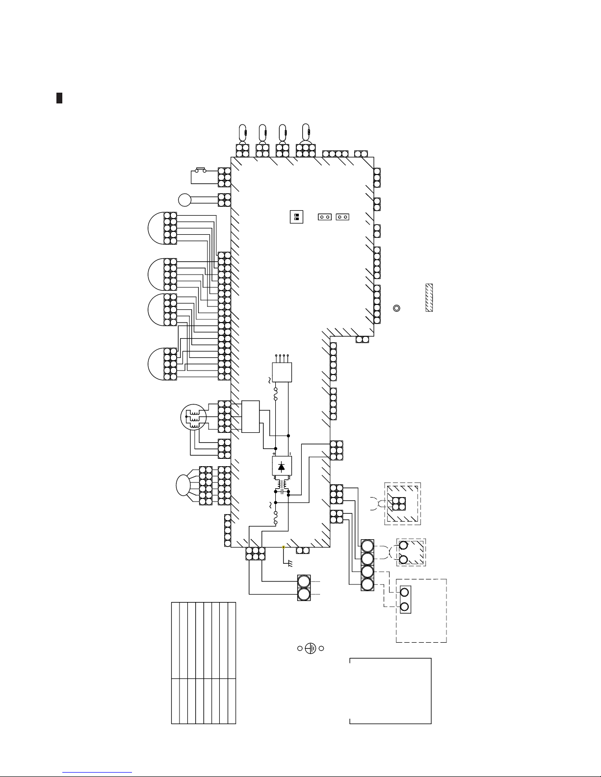
3. WIRING DIAGRAM
3-1. 4-Way Cassette Type
MMU-AP0072H2UL-1, AP0072H2UL, AP0092H2UL, AP0122H2UL, AP0152H2UL, AP0182H2UL,
AP0212H2UL, AP0242H2UL, AP0302H2UL, AP0362H2UL, AP0422H2UL

24
3-2. Compact 4-Way Cassette Type
MMU-AP0071MH2UL, AP0091MH2UL, AP0121MH2UL, AP0151MH2UL, AP0181MH2UL
䰞䰥303
䰞䰥302
Fuse
䰠6.3䰍
BLK
䰜䰻䱃䰱䰾 䰟䱁䰼䰼䰸䱅
208/230V-1-60
Ground Screw
䰜
䰐P
Control P.C. Board
(FANDRIVE)
䰠10
Motor
drive
MCC-1402
䰛䰜䰠䰕䰛䰚
Fuse
T3.15䰍䎏
Power
supply
䰒䰙
PMV
䰠䰏1
F䰟
Symbol
䰞䰥302
䰘䰙1,LM2
1.䫹䫹indicates䫹the䫹terminal䫹block letter.
Letter䫹at䫹inside䫹indicates䫹the terminal
number.
2.䫹A䫹dotted䫹line䫹and䫹broken䫹line indicate
the䫹wiring䫹at䫹site.
3. indicates䫹the䫹control䫹P.C䫹board.
U
May be Outdoor
unit or Indoor
䰘䰙1
35
4
䰘䰙2
unit
35
4
U
䰑䰤䰏䰠
2
1
䰒䰕䰘䰠䰑䰞
GRL
䰜䰚䰘
2
1
䯴䰣䰔䰕䯵
Adapter䫹for䫹
Wireless䫹Remote
BLK
䰏䰚001
WH
UU
BLK
BLU
BLU
䰠䰏2
䰠䰏䰖
䰠䰍
BLK
Louver䫹Motor
Float䫹Switch
Pulse䫹Motor䫹Valve
Drain䫹Pump䫹Motor
Drain䫹Control䫹Relay
䰜䰙䰢
䰒䰟
䰐P
Parts䫹Name
Temp䫹sensor
Temp䫹sensor
Temp䫹sensor
䰒䰭䰺䫹䰙䰻䱀o䰾
䰕䰺䰰䰻䰻䰾䫹temp䫹sensor
䰠䰍
䰠䰏䰖
䰠䰏䯾
䰠䰏䯽
䰒䰙
RED:RED
WHI:WHITE
YEL:YELLOW
BLU:BLUE
BLK:BLACK
GRY:GRAY
PNK:PINK
ORN:ORANGE
GRN:GREEN
BRW:BROWN
Wired Remote
Control
A
A
B
B
1
11
11
1
1
1
1
1
1
1
1
1
1
1
1
1
1
1
1
1
1
1
1
1
1
1
11
1
Indoor
Unit
Ground
Screw
COLOR
IDENTIFICATION
1
212
2
2
2
2
2
2
1
2
1
2
2
2
2
2
2
2
2
1
1
2
2
1
1
2
2
2
2
2
2
2
2
2
3
3
3
1
3
3
3
3
3
3
3
3
3
3
3
3
3
3
3
3
3
3
3
3
3
4
4
4
4
4
4
4
4
44
5
51
2
3
4
5
5
1
2
3
4
5
1
2
3
4
5
1
2
3
4
5
1
2
3
4
5
1
2
3
4
5
5
5
5
5
5
6
1
2
3
4
5
6
6
6
6
6
5
5
5
5
CN68
(BLU)
CN333
(WHI)
CN334
(WHI)
CN82
(BLU)
CN100
(BRW)
CN34
(RED)
CN104
(YEL)
CN102
(RED)
CN101
(BLK)
CN41
(BLU)
CN40
(BLU)
CN80
(GRN)
CN73
(RED)
CN33
(WHI)
CN70
(WHI)
CN20
(BLU)
CN32
(WHI)
CN50
(WHI)
CN67
(BLK)
CN66
(WHI)
CN44
(BRW)
DC20V
DC15V
DC12V
DC 7V
Flow Selector
Unit
250V ~
250V ~
L1
L2
RED
WHI
CN304
(GRY)
CN81
(BLK)
CN60
(WHI)
CN61
(YEL)
CN309
(YEL)

25
3-3. Ceiling Type
MMC-AP0181H2UL, AP0241H2UL, AP0361H2UL, AP0421H2UL
Adapter䫹for䫹
Wireless䫹Remote
RED
Power Supply
208/230-1-60
Indoor Unit
Ground Screw
L2L1
unit
Wired
Remote
Control
1
unit or Indoor
May be Outdoor
U
U
1
2
Closed-end
Connector
WHI
U
A
2
U
B
Ground Screw
Flow Selector Unit
Drain䫹Pump䫹Motor
Pulse䫹Motor䫹Valve
Drain䫹Control䫹Relay
PMV
TCJ
TC2
DP
LM
RY302
FS
Temp䫹sensor
Louver䫹Motor
Temp䫹sensor
Float䫹Switch
䰕䰺䰰䰻䰻䰾䫹temp䫹sensor
Symbol
TA
TC1
FM
Temp䫹sensor
Parts䫹Name
FanޓMotor
㨀㧭
㨀㧯㧶
㨀㧯㧞
㨀㧯㧝
㧲㧵㧸㨀㧱㧾
1
1
CN50
㧔WHI㧕
Letter䫹at䫹inside䫹indicates䫹the䫹terminal䫹number.
1.䫹䫹indicates䫹the䫹terminal䫹block䫹letter.
3.䫹䫹䫹䫹䫹indicates䫹the䫹control䫹P.C䫹board.
2.䫹A䫹dotted䫹lime䫹and䫹broken䫹line䫹indicate䫹the䫹wiring䫹at䫹site.
BLK
(WHI)
WHI
2
2
1
1
CN001
㧔BLU㧕
CN40
CN41
㧔BLU㧕
33
BLK
BLK
BLU
BLU
1 2
2
11
1
2
31
31
231
CN309
㧔YEL㧕
WHI
RED
RY302
㧰P
RY303
Fuse
P301
CN66
㧔WHI㧕
33
2
1
BLK
(GRY)
CN304
CN67
(BLK)
33
3
1
11
㧔WHI㧕
CN334
CN68
(BLU)
11
32
45
4
5
1
1
Control P.C. Board
for Indoor Unit
6
MCC-1402
㧔WHI㧕
2
1
45
653
㨀㧝㧜
4
㧔YEL㧕
CN61
1
2
1
FANDRIVE
435
2
OPTION
CN32
㧔WHI㧕
CN60
2
CN20
㧔BLU㧕
㧔RED㧕
3
2
1
5
1
4
CN81
㧔BLK㧕
CN70
2
453
GRL
2
1
㧱㨄㧯㨀
1
CN73
㧔WHI㧕
Power
supply
circuit
motor
䰰rive
Fuse
T3.15A
6
㧔WHI㧕
5
5
3
3
6
1
1
CN333
FM
25143
㧔BLU㧕
21 543
5
6
4
5
6
4
23
23
CN82
PMV
22
CN104
CN102
㧔BLK㧕
CN100
㧔BRW㧕
CN101
㧔GRN㧕
㧔RED㧕
DC15V
DC12V
DC7V
DC20V
1
1
2
1
3
2
3
CN80
㧼㧺㧸
3
2
1
2
1
2
1
2
1
1
1
㧔YEL㧕
34
2
5
1
34
2
1
34
2342
1
1
CN33
5
5
5
㧔WHI㧕
䰘䰙
㧲㧿
1
CN34
㧔RED㧕
3
3
2
1
RED:RED
WHI:WHITE
YEL:YELLOW
BLU:BLUE
BLK:BLACK
GRY:GRAY
PNK:PINK
ORN:ORANGE
GRN:GREEN
BRW:BROWN
A B
COLOR
IDENTIFICATION
Sold
Separately

26
㧔㧮㧸㨁㧕
㧯㧺㧝㧜㧜
㧔㧮㧾㨃㧕
㧔㧮㧸㨁㧕
㧯㧺㧝㧜㧝
㧔㧳㧾㧺㧕
㧯㧺㧝㧜㧟
㧔㨅㧱㧸㧕
㧔㨃㧴㧵㧕
㧯㧺㧝㧜㧠
㧯㧺㧝㧜㧞
㧼㧺㧸㧱㧹㧳
㧮㧾㨃
㧔㨃㧴㧵㧕
㧔㨃㧴㧵㧕
㧔㧮㧸㨁㧕
㧮㧸㨁
㧠
㧠
㧤
㧤
㧵㧺㧲㧾㧭㧾㧱㧰ޓ㧾㧭㨅㧿ޓ㧾㧱㧯㧱㧵㨂㧱
㧭㧺㧰ޓ㧵㧺㧰㧵㧯㧭㨀㧵㧻㧺ޓ㧼㧭㧾㨀㧿
㧔㧹㧯㧯㧙㧡㧜㧠㧠㧕
㧳㧾㧺㧒
FLOW SELECTOR UNIT
(Sold sepalat㪼ly)
Power Supply
㧟㧝㧞
㨅㧱㧸
㧥
㧠㧡
㧯㧺㧟㧜㧥
㧔㨅㧱㧸㧕
㧔㧮㧸㧷㧕
㧯㧺㧢㧣
HEAT EXCHANGER
㧡
㧟㧟
㧝㧝
㨃㧴㧵
㧾㧱㧰
㧯㧺㧤㧝㧔㧮㧸㧷㧕
㧟
㧟
㨅㧱㧸
㧮㧾㨃
㨃㧴㧵
㧞㧝
㧞㧝
㧝㧟
㧮㧸㨁
㧮㧸㨁
㧟
㧟
㧝㧞
㧞
㧼㧺㧷
㧳㧾㨅
㧠㧡
㧡㧠
㨀㧟㧚㧝㧡㧭ޓ㧞㧡㧜㨂㨪
㧲㧟㧜㧝ޓ㧲㨁㧿㧱
㧔㧹㧯㧯㧙㧝㧡㧝㧜㧕
Control P.C board for indoor unit
㧔㨃㧴㧵㧕
㧲㧭㧺㧰㧾㧵㨂㧱
㧝㧞
㧞
㧞
㧝
㧣㧠㧡㧢
㧢㧡㧠㧣
㧟
㧟
㧯㧺㧟㧞
㧔㧳㧾㧺㧕
㧔㨃㧴㧵㧕
㧔㨅㧱㧸㧕
㧻㧼㨀㧵㧻㧺
㧞
㧢
㧞㧠㧟㧝
㧟㧠㧞㧝 㧡
㧴㧭
㧠㧟㧞㧝 㧡㧢
㧝
㧝㧞㧟
㧠㧟 㧡㧢
㧯㧺㧢㧝
㧯㧺㧤㧜
㧯㧺㧢㧜
㧮㧸㨁
㧮㧸㨁
㧮㧸㨁
㧡㧤㧣㧢
㧣㧤
㨃㧴㧵
㧯㧺㧞㧝㧟㧔㨃㧴㧵㧕
㧼㧻㨃㧱㧾
㧯㧵㧾㧯㨁㧵㨀
㧿㨁㧼㧼㧸㨅
㧰㧯㧣㨂
㧰㧯ޓ㧜㨂
㧰㧯㧝㧞㨂
㧰㧯㧝㧡㨂
$.-
5
㧳㧾㧺㧒㨅㧱㧸
㧼㧺㧷ޓ㧦ޓ㧼㧵㧺㧷
㧳㧾㧺ޓ㧦ޓ㧳㧾㧱㧱㧺
㧻㧾㧺ޓ㧦ޓ㧻㧾㧭㧺㧳㧱
㧳㧾㧺㧒㨅㧱㧸ޓ㧦ޓ㧳㧾㧱㧱㧺ޓ㧒
㧯㧺㧞㧞
㨅㧱㧸㧸㧻㨃
㨅㧱㧸ޓ㧦ޓ㨅㧱㧸㧸㧻㨃
㧳㧾㨅ޓ㧦ޓ㧳㧾㧭㨅
㧮㧸㧷ޓ㧦ޓ㧮㧸㧭㧯㧷
㧮㧸㨁ޓ㧦ޓ㧮㧸㨁㧱
㧮㧾㨃ޓ㧦ޓ㧮㧾㧻㨃㧺
㨃㧴㧵ޓ㧦ޓ㨃㧴㧵㨀㧱
㧾㧱㧰ޓ㧦ޓ㧾㧱㧰
㧯㧻㧸㧻㧾ޓ㧵㧰㧱㧺㨀㧵㧲㧵㧯㧭㨀㧵㧻㧺
(#0
/1614
㧯㧺㧞㧝㧜
㧢
㧢
㧮㧸㨁
(
㧔㨃㧴㧵㧕
㧡
㧴㧮㧿
㧯㧺㧡㧜
㧟㧞 㧠㧝
㧝㧞
㧝㧞
㨃㧴㧵
㨅㧱㧸
㧡㧢 㧠
㧢㧡
㧠
㧻㧾㧺
㧮㧸㨁
㧮㧾㨃
㧾㧱㧰
㧯㧺㧤㧞
㧟
㧟
㨂㧭㧸㨂㧱
㧹㧻㨀㧻㧾
㧼㨁㧸㧿㧱
㧢
㧢
㨅㧱㧸
㧡 㧠㧟
㧡㧟㧠
㧝
㧝
㨅㧱㧸
㨃㧴㧵
㧮㧸㧷
㧾㧱㧰
㧯㧺㧠㧠
㧝㧞
㧯㧺㧟㧟
㧠
㧠
㧡
㧡
㧞
㧟㧞㧟
㨅㧱㧸
㨅㧱㧸
㨅㧱㧸
㨃㧴㧵
㧝
㧡
㧹㧻㨀㧻㧾
㧸㧻㨁㨂㧱㧾
㧝㧞㧠㧟
U2
㧔㧮㧸㨁㧕
U2
㧞
(Sold Separately)
㧿㧱㧺㧿㧻㧾
㧔㨀㧭㧕
㧮㧸㧷
㧮㧸㧷
㧮㧸㧷
㧝㧝
㧞
㧞
㧞㧞
㧝㧝
㧮㧸㧷
㨀㧴㧱㧾㧹㧻
㧔㨀㧯㧶㧕
㧿㧱㧺㧿㧻㧾
㧱㨄㧯㧴㧭㧺㧳㧱㧾
㧴㧱㧭㨀
䰏䰚䯽䎋䎺䎫䎬䎌
䎃
CONTROL
WIRED REMOTE
䎥䎯䎮
䎺䎫䎬
㧮㧸㧷
㧔㨀㧯㧝㧕
㧟㧟
㨀㧲
㧮㧸㧷
㧝
㧝
㧞
㧝
㧞
㧮㧸㧷
㧿㧱㧺㧿㧻㧾
㧔㨀㧯㧞㧕
㧴㧱㧭㨀
㧱㨄㧯㧴㧭㧺㧳㧱㧾
㧮㧸㧷
㨃㧴㧵
㧯㧺㧠㧝
㧝㧝
㧞
㧝
㧝
㧞
㧮㧸㧷
㧟㧟
㧿㧱㧺㧿㧻㧾
㧴㧱㧭㨀
㧱㨄㧯㧴㧭㧺㧳㧱㧾
A
B
㧮㧸㨁
㧮㧸㨁
㧯㧺㧠㧜
㧞㧞
㧝㧝
U1 U1
or Indoor unit
May be Outdoor unit
㧝㧚٧KPFKECVGUVJGVGTOKPCNDNQEM
.GVVGTCVKPUKFGKPFKECVGUVJGVGTOKPCNPWODGT
㧞㧚#FQVVGFNKPGCPFDTQMGPNKPGKPFKECVGVJGYKTKPICVUKVG
㧟㧚KPFKECVGUVJGEQPVTQN2%DQCTF
KPFKECVGUVJGEQPVTQN2%DQCTF
L1
L2
3-4. High Wall Type
MMK-AP0073H2UL, AP0093H2UL, AP0123H2UL, AP0153H2UL, AP0183H2UL, AP0243H2UL

27
4. PARTS RATING
4-1. 4-Way Cassette Type
4-2. Compact 4-Way Cassette Type
Model MMU-AP
Fan motor
Moter for horizontal grille
Pulse motor
Pulse motor valve
TA sensor
TC1 sensor
TC2 sensor
TCJ sensor
Float switch
Drain pump motor
0071MH2UL 0091MH2UL 0121MH2UL 0151MH2UL 0181MH2UL
SWF-340U60-1
MP24ZN3N
EFM-MD12TF-1
EDM-B25YGTF-3 EDM-B40YGTF-3
Lead wire length : 6.1 in (155 mm) Vinyl tube
Ø4 size lead wire length : 55.12 in (1400 mm) Vinyl tube (Blue) (Blue)
Ø6 size lead wire length : 55.12in (1400 mm) Vinyl tube (Black)
Ø6 size lead wire length : 55.12 in (1400 mm) Vinyl tube (Red)
FS-0218-103
APD-1406
Model MMU-
Fan motor
Moter for horizontal grille
Pulse motor
Pulse motor valve
TA sensor
TC1 sensor
TC2 sensor
TCJ sensor
Float switch
Drain pump motor
SWF-340U60-2
ICF-340
U150-1
MP24ZN3N
EFM-MD12TF-1
EDM-B40YGTF-2
EDM-B60
YGTF-1
Lead wire length : 12.2 in (310 mm) Vinyl tube
Ø4 size lead wire length : 47.24 in (1200 mm) Vinyl tube (Blue)
Ø6 size lead wire length : 39.37 in (1000 mm) Vinyl tube (Black)
Ø6 size lead wire length : 39.37 in (1000 mm) Vinyl tube (Red)
FS-0218-102
MDP-1401
AP042AP036AP030AP024AP021AP018AP015AP012AP009AP007

28
4-3. Ceiling Type
4-4. High Wall Type
Model MMC-
Fan motor
Driving motor for horizontal grille
Pulse motor
Pulse motor valve
TA sensor
TC1 sensor
TC2 sensor
TCJ sensor
AP0181H2UL AP0241H2UL AP0361H2UL AP0421H2UL
SWF-340U60-1A SWF-340U60-2A SWF-340U120-2A
MP24Z2
EFM-MD12TF-1
EBM-B40YGTF- 3 EDM-B60YGTF-1
Lead wire length : 6.1 in (155 mm) Vinyl tube
Ø4 size lead wire length : 47.24 in (1200 mm) Vinyl tube (Blue)
Ø6 size lead wire length : 47.24 in (1200 mm) Vinyl tube (Black)
Ø6 size lead wire length : 47.24 in (1200 mm) Vinyl tube (Red)
No.
1
2
3
4
5
6
7
Model MMK-AP
Fan motor (for indoor)
Grille motor
Thermo. sensor (TA sensor)
Heat exchanger sensor (TC1 sensor)
Heat exchanger sensor (TC2 sensor)
Heat exchanger sensor (TCJ sensor)
PMV motor
ICF-340U30-1: Output (Rated) 30W, 280-340V DC
MP24Z3T: Output (Rated) 1W, 16 poles DC
12.5 in (318 mm): 10 kΩ at 77°F (25°C)
Ø0.24, 23.62 in (Ø4,600 mm):
10 kΩ at 77°F (25°C)
Ø0.24, 31.5 in (Ø4,800 mm):
10 kΩ at 77°F (25°C)
Ø0.16, 31.5 in (Ø4,800 mm):
10 kΩ at 77°F (25°C)
EDM-MD12TF: 12 V DC
0073H2UL 0093H2UL 0123H2UL 0153H2UL 0183H2UL 0243H2UL

29
Air heat exchanger
at indoor side
Fan
M
Fan motor
Sensor
(TA)
Sensor
(TC1)
Gas sideLiquid side
Strainer
Capillary tube
Pulse Motor
Valve (PMV)
Strainer
Sensor
(TCJ)
Sensor
(TC2)
5. REFRIGERATING CYCLE DIAGRAM
Functional part name
Pulse Motor Valve PMV
Temp. sensor 1. TA
2. TC1
3. TC2
4. TCJ
Functional outline
(Connector CN082 (6P): Blue)
1) Controls super heat in cooling operation
2) Controls under cool in heating operation
3) Recovers refrigerant oil in cooling operation
4) Recovers refrigerant oil in heating operation
(Connector CN104 (2P): MMU, MMC: Yellow, MMK: White)
1) Detects indoor suction temperature
(Connector CN100 (3P): Brown)
1) Controls PMV super heat in cooling operation
(Connector CN101 (2P): MMU, MMC: Black, MMK: Blue)
1) Controls PMV under cool in heating operation
(Connector CN102 (2P): MMU, MMC: Red, MMK: Yellow)
1) Controls PMV super heat in cooling operation

30
No.
1
2
3
Item
When power
supply is reset
Operation
mode selection
Room temp.
control
Outline of specifications
1) Distinction of outdoor unit
When the power supply is reset, the outdoors are
distinguished and the control is selected according to the
distinguished result.
2) Setting of indoor fan speed and existence of air direction
adjustment
Based on EEPROM data, select setting of the indoor fan
speed and the existence of air direction adjustment.
3) If resetting the power supply during occurrence of a
trouble, the check code is once cleared. After ON/OFF
button of the remote control was pushed and the operation
was resumed, if the abnormal status continues, the check
code is again displayed on the remote control.
1) Based on the operation mode selecting command from the
remote control, the operation mode is selected.
1) Adjustment range: Remote control setup temperature (°F [°C] )
Remarks
Air speed (rpm)/
Air direction adjustment
Wired type
Wireless type
COOL/DRY
64°F [18°C] to 84°F [29°C]
63°F [17°C] to 86°F [30°C]
HEAT
64°F [18°C] to 84°F [29°C]
63°F [17°C] to 86°F [30°C]
6. CONTROL OUTLINE
6-1. 4-Way Cassette Type, Compact 4-Way Type, Ceiling Type
2) Using the Item code 06, the setup temperature in heating
operation can be corrected.
Setting at shipment
Shift of suction
temperature in heating
operation
Except while sensor of
the remote control is
controlled
(Code No. [32], “0001”)
Setup data 2
Setup data
Setup temp.
Correction
0246
+0°F +3.6°F +7.2°F +10.8°F
[+0°C] [+2°C] [+4°C] [+6°C]
Remote control
command
STOP
FAN
COOL
DRY
HEAT
Control outline
Air conditioner stops.
Fan operation
Cooling operation
Dry operation
Heating operation
 Loading...