


MMY-MAP1201HT8
SUPER MODULAR MULTI
R410A
Quick reference
FILE NO : A04-004
Pipe
length
Height
difference
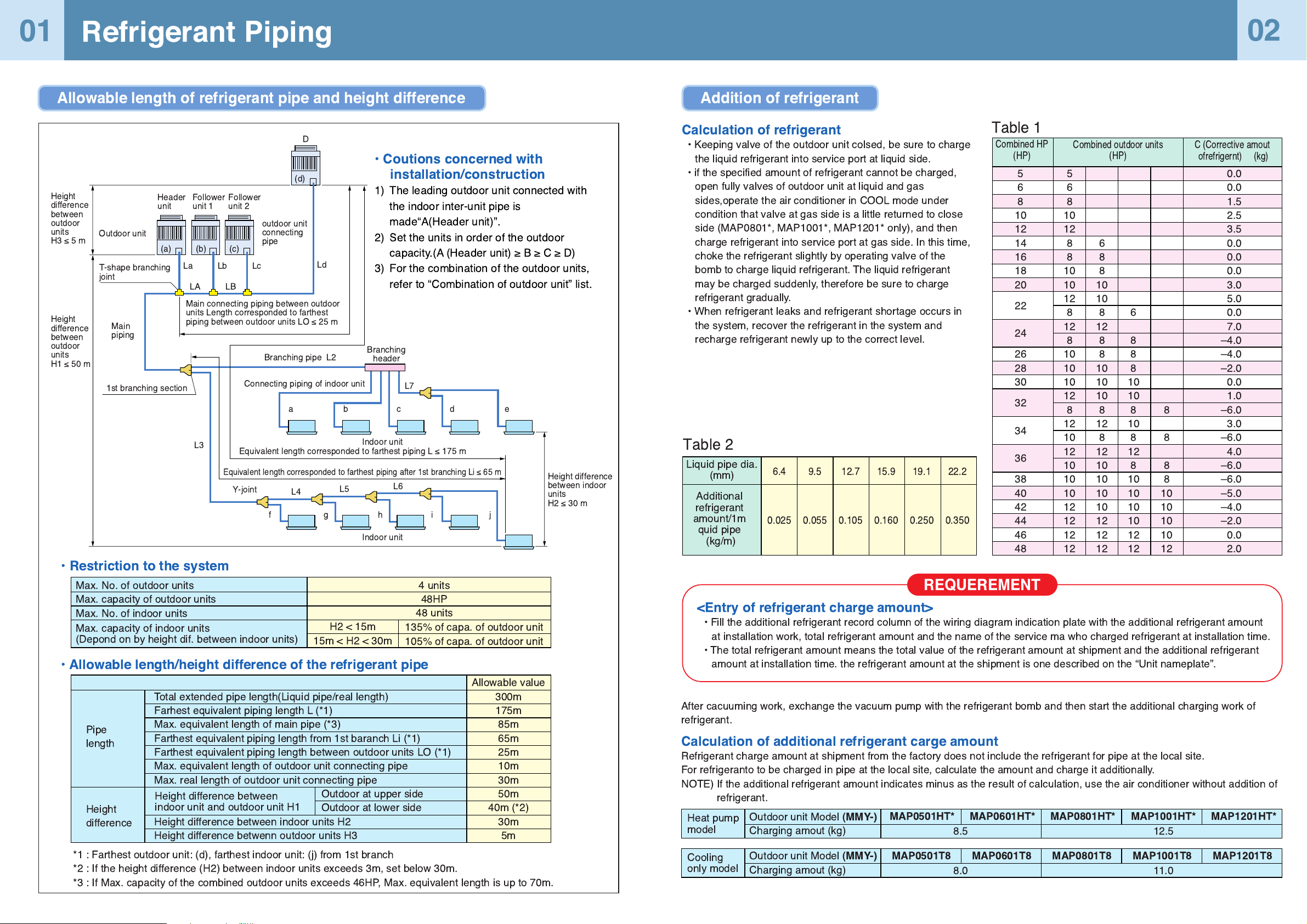
Total extended pipe length(Liquid pipe/real length)
Farhest equivalent piping length L (*1)
Max. equivalent length of main pipe (*3)
Farthest equivalent piping length from 1st baranch Li (*1)
Farthest equivalent piping length between outdoor units LO (*1)
Max. equivalent length of outdoor unit connecting pipe
Max. real length of outdoor unit connecting pipe
Outdoor at upper side
Outdoor at lower side
Height difference between indoor units H2
Height difference betwenn outdoor units H3
Allowable value
300m
175m
85m
65m
25m
10m
30m
50m
40m (*2)
30m
5m
Height difference between
indoor unit and outdoor unit H1
*1 : Farthest outdoor unit: (d), farthest indoor unit: (j) from 1st branch
*2 : If the height difference (H2) between indoor units exceeds 3m, set below 30m.
*3 : If Max. capacity of the combined outdoor units exceeds 46HP, Max. equivalent length is up to 70m.
Calculation of refrigerant
¥ Keeping valve of the outdoor unit colsed, be sure to charge
the liquid refrigerant into service port at liquid side.
¥ if the specified amount of refrigerant cannot be charged,
open fully valves of outdoor unit at liquid and gas
sides,operate the air conditioner in COOL mode under
condition that valve at gas side is a little returned to close
side (MAP0801*, MAP1001*, MAP1201* only), and then
charge refrigerant into service port at gas side. In this time,
choke the refrigerant slightly by operating valve of the
bomb to charge liquid refrigerant. The liquid refrigerant
may be charged suddenly, therefore be sure to charge
refrigerant gradually.
¥ When refrigerant leaks and refrigerant shortage occurs in
the system, recover the refrigerant in the system and
recharge refrigerant newly up to the correct level.
<Entry of refrigerant charge amount>
¥ Fill the additional refrigerant record column of the wiring diagram indication plate with the additional refrigerant amount
at installation work, total refrigerant amount and the name of the service ma who charged refrigerant at installation time.
¥ The total refrigerant amount means the total value of the refrigerant amount at shipment and the additional refrigerant
amount at installation time. the refrigerant amount at the shipment is one described on the ÒUnit nameplateÓ.
After cacuuming work, exchange the vacuum pump with the refrigerant bomb and then start the additional charging work of
refrigerant.
Calculation of additional refrigerant carge amount
Refrigerant charge amount at shipment from the factory does not include the refrigerant for pipe at the local site.
For refrigeranto to be charged in pipe at the local site, calculate the amount and charge it additionally.
NOTE) If the additional refrigerant amount indicates minus as the result of calculation, use the air conditioner without addition of
refrigerant.
Combined HP
(HP)
Combined outdoor units
(HP)
C (Corrective amout
ofrefrigernt) (kg)
Table 1
Table 2
5
6
8
10
12
14
16
18
20
22
24
26
28
30
32
34
36
38
40
42
44
46
48
5
6
8
10
12
8
8
10
10
12
8
12
8
10
10
10
12
8
12
10
12
10
10
10
12
12
12
12
6
8
8
10
10
8
12
8
8
10
10
10
8
12
8
12
10
10
10
10
12
12
12
6
8
8
8
10
10
8
10
8
12
8
10
10
10
10
12
12
8
8
8
8
10
10
10
10
12
0.0
0.0
1.5
2.5
3.5
0.0
0.0
0.0
3.0
5.0
0.0
7.0
Ð4.0
Ð4.0
Ð2.0
0.0
1.0
Ð6.0
3.0
Ð6.0
4.0
Ð6.0
Ð6.0
Ð5.0
Ð4.0
Ð2.0
0.0
2.0
Liquid pipe dia.
(mm)
Additional
refrigerant
amount/1m
quid pipe
(kg/m)
6.4
0.025
9.5
0.055
12.7
0.105
15.9
0.160
19.1
0.250
22.2
0.350
Heat pump
model
Outdoor unit Model
(MMY-)
Charging amout (kg)
MAP0501HT* MAP0601HT* MAP0801HT* MAP1001HT* MAP1201HT*
8.5 12.5
Cooling
only model
Outdoor unit Model
(MMY-)
Charging amout (kg)
MAP0501T8 MAP0601T8 MAP0801T8 MAP1001T8 MAP1201T8
8.0 11.0
REQUEREMENT
01
Refrigerant Piping
Allowable length of refrigerant pipe and height difference Addition of refrigerant
Max. No. of outdoor units
Max. capacity of outdoor units
Max. No. of indoor units
¥ Coutions concerned with
installation/construction
1) The leading outdoor unit connected with
the indoor inter-unit pipe is
madeÒA(Header unit)Ó.
2) Set the units in order of the outdoor
capacity.(A (Header unit) ³ B ³ C ³ D)
3) For the combination of the outdoor units,
refer to ÒCombination of outdoor unitÓ list.
02
D
(d)
(c)
(b)
(a)
La Lc
Ld
Lb
LA LB
Y-joint
aedcb
L7
L4
L6
L5
Outdoor unit
outdoor unit
connecting
pipe
Main connecting piping between outdoor
units Length corresponded to farthest
piping between outdoor units LO ² 25 m
T-shape branching
joint
Main
piping
1st branching section
L3
Indoor unit
Indoor unit
Height difference
between indoor
units
H2 ² 30 m
Equivalent length corresponded to farthest piping L ² 175 m
Equivalent length corresponded to farthest piping after 1st branching Li ² 65 m
Connecting piping of indoor unit
Branching pipe L2
Branching
header
Header
unit
Follower
unit 1
Follower
unit 2
Height
difference
between
outdoor
units
H3²5m
Height
difference
between
outdoor
units
H1 ² 50 m
¥ Restriction to the system
¥ Allowable length/height difference of the refrigerant pipe
Max. capacity of indoor units
(Depond on by height dif. between indoor units)
H2 < 15m
15m < H2 < 30m
135% of capa. of outdoor unit
105% of capa. of outdoor unit
4 units
48HP
48 units
fjihg
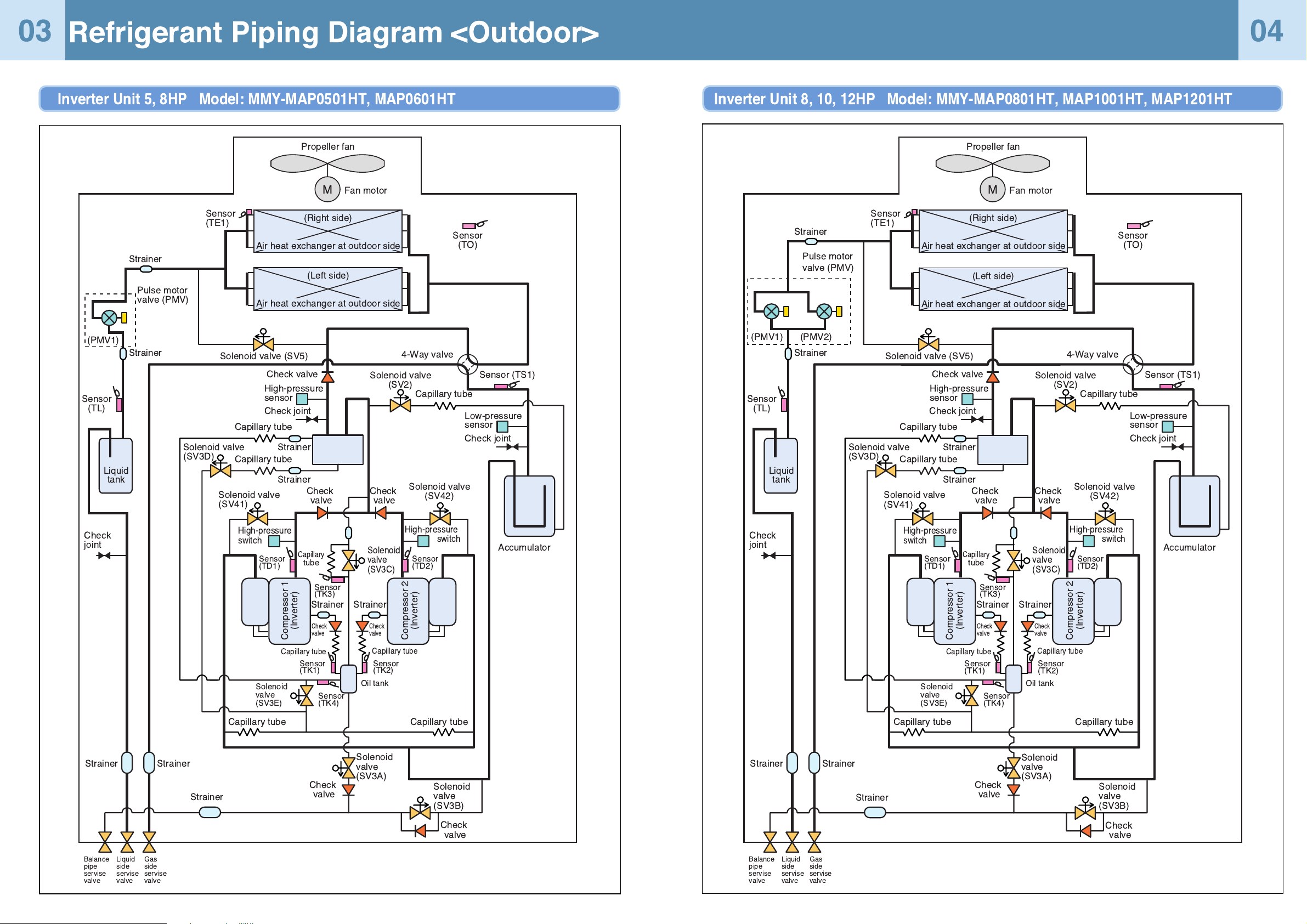
Refrigerant Piping Diagram <Outdoor>
Inverter Unit 5, 8HP Model: MMY-MAP0501HT, MAP0601HT
03
04
Capillary tube
Capillary
tube
Capillary tube
Propeller fan
Fan motor
Sensor
(TO)
Sensor (TS1)
Sensor
(TL)
Sensor
(TE1)
(Right side)
(Left side)
Solenoid valve
(SV2)
Solenoid valve (SV5)
Solenoid valve
(SV41)
Solenoid
valve
(SV3A)
Solenoid
valve
(SV3E)
Solenoid
valve
(SV3B)
Solenoid valve
(SV3D)
Solenoid
valve
(SV3C)
4-Way valve
Check joint
Low-pressure
sensor
Accumulator
Check joint
Check
joint
High-pressure
sensor
High-pressure
switch
Oil
separator
Check valve
Check
valve
Check
valve
Check
valve
Check
valve
Compressor 1
(Inverter)
Strainer
Strainer
Sensor
(TK1)
Sensor
(TK4)
Sensor
(TK3)
Capillary tube
Capillary tube
Capillary tube
Strainer
Strainer
Strainer
(PMV1)
Strainer
StrainerStrainer
Capillary tube
Capillary tube
Solenoid valve
(SV42)
High-pressure
switch
Check
valve
Check
valve
Compressor 2
(Inverter)
Strainer
Sensor
(TK2)
Sensor
(TD2)
Sensor
(TD1)
Liquid
tank
Oil tank
Balance
pipe
servise
valve
Liquid
side
servise
valve
Gas
side
servise
valve
Pulse motor
valve (PMV)
Air heat exchanger at outdoor side
Air heat exchanger at outdoor side
M
Inverter Unit 8, 10, 12HP Model: MMY-MAP0801HT, MAP1001HT, MAP1201HT
Capillary tube
Capillary
tube
Capillary tube
Propeller fan
Fan motor
Sensor
(TO)
Sensor (TS1)
Sensor
(TL)
Sensor
(TE1)
(Right side)
(Left side)
Solenoid valve
(SV2)
Solenoid valve (SV5)
Solenoid valve
(SV41)
Solenoid
valve
(SV3A)
Solenoid
valve
(SV3E)
Solenoid
valve
(SV3B)
Solenoid valve
(SV3D)
Solenoid
valve
(SV3C)
4-Way valve
Check joint
Low-pressure
sensor
Accumulator
Check joint
Check
joint
High-pressure
sensor
High-pressure
switch
Oil
separator
Check valve
Check
valve
Check
valve
Check
valve
Check
valve
Compressor 1
(Inverter)
Strainer
Strainer
Sensor
(TK1)
Sensor
(TK4)
Sensor
(TK3)
Capillary tube
Capillary tube
Capillary tube
Strainer
Strainer
Strainer
Strainer
StrainerStrainer
Capillary tube
Capillary tube
Solenoid valve
(SV42)
High-pressure
switch
Check
valve
Check
valve
Compressor 2
(Inverter)
Strainer
Sensor
(TK2)
Sensor
(TD2)
Sensor
(TD1)
Liquid
tank
Oil tank
Balance
pipe
servise
valve
Liquid
side
servise
valve
Gas
side
servise
valve
Pulse motor
valve (PMV)
Air heat exchanger at outdoor side
Air heat exchanger at outdoor side
M
(PMV1) (PMV2)
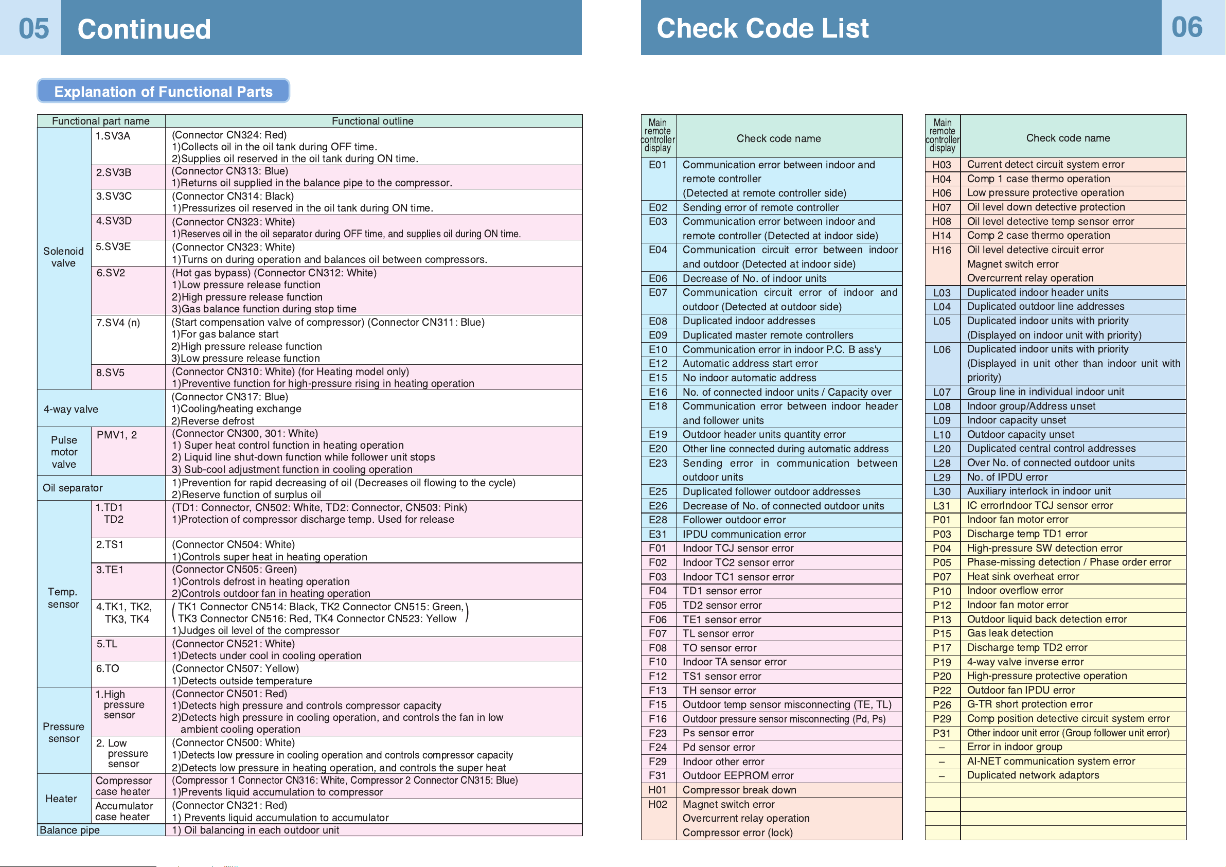
Continued
Check Code List
05
06
Explanation of Functional Parts
Functional outline
Solenoid
valve
Functional part name
4-way valve
Pulse
motor
valve
Oil separator
Temp.
sensor
Pressure
sensor
Heater
Balance pipe
(Connector CN324: Red)
1)Collects oil in the oil tank during OFF time.
2)Supplies oil reserved in the oil tank during ON time.
(Connector CN313: Blue)
1)Returns oil supplied in the balance pipe to the compressor.
1.SV3A
2.SV3B
3.SV3C
4.SV3D
6.SV2
5.SV3E
7.SV4 (n)
8.SV5
PMV1, 2
2.TS1
3.TE1
4.TK1, TK2,
TK3, TK4
5.TL
6.TO
2. Low
pressure
sensor
Compressor
case heater
1.TD1
TD2
1.High
pressure
sensor
Accumulator
case heater
(Connector CN314: Black)
1)Pressurizes oil reserved in the oil tank during ON time.
(Connector CN323: White)
1)Reserves oil in the oil separator during OFF time, and supplies oil during ON time.
(Connector CN323: White)
1)Turns on during operation and balances oil between compressors.
(Hot gas bypass) (Connector CN312: White)
1)Low pressure release function
2)High pressure release function
3)Gas balance function during stop time
(Start compensation valve of compressor) (Connector CN311: Blue)
1)For gas balance start
2)High pressure release function
3)Low pressure release function
(Connector CN310: White) (for Heating model only)
1)Preventive function for high-pressure rising in heating operation
(Connector CN317: Blue)
1)Cooling/heating exchange
2)Reverse defrost
(Connector CN300, 301: White)
1) Super heat control function in heating operation
2) Liquid line shut-down function while follower unit stops
3) Sub-cool adjustment function in cooling operation
1)Prevention for rapid decreasing of oil (Decreases oil flowing to the cycle)
2)Reserve function of surplus oil
(TD1: Connector, CN502: White, TD2: Connector, CN503: Pink)
1)Protection of compressor discharge temp. Used for release
(Connector CN504: White)
1)Controls super heat in heating operation
(Connector CN505: Green)
1)Controls defrost in heating operation
2)Controls outdoor fan in heating operation
TK1 Connector CN514: Black, TK2 Connector CN515: Green,
TK3 Connector CN516: Red, TK4 Connector CN523: Yellow
1)Judges oil level of the compressor
(Connector CN521: White)
1)Detects under cool in cooling operation
(Connector CN507: Yellow)
1)Detects outside temperature
(Connector CN501: Red)
1)Detects high pressure and controls compressor capacity
2)Detects high pressure in cooling operation, and controls the fan in low
ambient cooling operation
(Connector CN500: White)
1)
Detects low pressure in cooling operation and controls compressor capacity
2)Detects low pressure in heating operation, and controls the super heat
(Compressor 1 Connector CN316: White, Compressor 2 Connector CN315: Blue)
1)Prevents liquid accumulation to compressor
(Connector CN321: Red)
1) Prevents liquid accumulation to accumulator
1) Oil balancing in each outdoor unit
()
Communication error between indoor and
remote controller
(Detected at remote controller side)
Sending error of remote controller
Communication error between indoor and
remote controller (Detected at indoor side)
Communication circuit error between indoor
and outdoor (Detected at indoor side)
Decrease of No. of indoor units
Communication circuit error of indoor and
outdoor (Detected at outdoor side)
Duplicated indoor addresses
Duplicated master remote controllers
Communication error in indoor P.C. B ass'y
Automatic address start error
No indoor automatic address
No. of connected indoor units / Capacity over
Communication error between indoor header
and follower units
Outdoor header units quantity error
Other line connected during automatic address
Sending error in communication between
outdoor units
Duplicated follower outdoor addresses
Decrease of No. of connected outdoor units
Follower outdoor error
IPDU communication error
Indoor TCJ sensor error
Indoor TC2 sensor error
Indoor TC1 sensor error
TD1 sensor error
TD2 sensor error
TE1 sensor error
TL sensor error
TO sensor error
Indoor TA sensor error
TS1 sensor error
TH sensor error
Outdoor temp sensor misconnecting (TE, TL)
Outdoor pressure sensor misconnecting (Pd, Ps)
Ps sensor error
Pd sensor error
Indoor other error
Outdoor EEPROM error
Compressor break down
Magnet switch error
Overcurrent relay operation
Compressor error (lock)
Current detect circuit system error
Comp 1 case thermo operation
Low pressure protective operation
Oil level down detective protection
Oil level detective temp sensor error
Comp 2 case thermo operation
Oil level detective circuit error
Magnet switch error
Overcurrent relay operation
Duplicated indoor header units
Duplicated outdoor line addresses
Duplicated indoor units with priority
(Displayed on indoor unit with priority)
Duplicated indoor units with priority
(Displayed in unit other than indoor unit with
priority)
Group line in individual indoor unit
Indoor group/Address unset
Indoor capacity unset
Outdoor capacity unset
Duplicated central control addresses
Over No. of connected outdoor units
No. of IPDU error
Auxiliary interlock in indoor unit
IC errorIndoor TCJ sensor error
Indoor fan motor error
Discharge temp TD1 error
High-pressure SW detection error
Phase-missing detection / Phase order error
Heat sink overheat error
Indoor overflow error
Indoor fan motor error
Outdoor liquid back detection error
Gas leak detection
Discharge temp TD2 error
4-way valve inverse error
High-pressure protective operation
Outdoor fan IPDU error
G-TR short protection error
Comp position detective circuit system error
Other indoor unit error (Group follower unit error)
Error in indoor group
AI-NET communication system error
Duplicated network adaptors
E01
E02
E03
E04
E06
E07
E08
E09
E10
E12
E15
E16
E18
E19
E20
E23
E25
E26
E28
E31
F01
F02
F03
F04
F05
F06
F07
F08
F10
F12
F13
F15
F16
F23
F24
F29
F31
H01
H02
H03
H04
H06
H07
H08
H14
H16
L03
L04
L05
L06
L07
L08
L09
L10
L20
L28
L29
L30
L31
P01
P03
P04
P05
P07
P10
P12
P13
P15
P17
P19
P20
P22
P26
P29
P31
Ð
Ð
Ð
Check code name
Check code name
Main
remote
controller
display
Main
remote
controller
display
SW04 SW05 SW15
D600 D601 D602 D603 D604
1
SW01
1
SW02
1
SW03
Header unit interface P.C. board
U1 U2 U3 U4 U5 U6
Header unit interface P.C. board
1 2 3 4
ON
SW11
1 2 3 4
ON
SW12
1 2 3 4
ON
SW06
1 2 3 4
ON
SW07
1 2 3 4
ON
SW09
1 2 3 4
ON
SW10
1
ON
SW08
1 2 3 4
ON
SW13
1 2 3 4
ON
SW14
UNIT
SET
CL
UNIT
SET
CL
For internal
wiring between
indoor and
outdoor
For wiring of
central control
system
For internal
wiring between
outdoor units
Address Setup
07
08
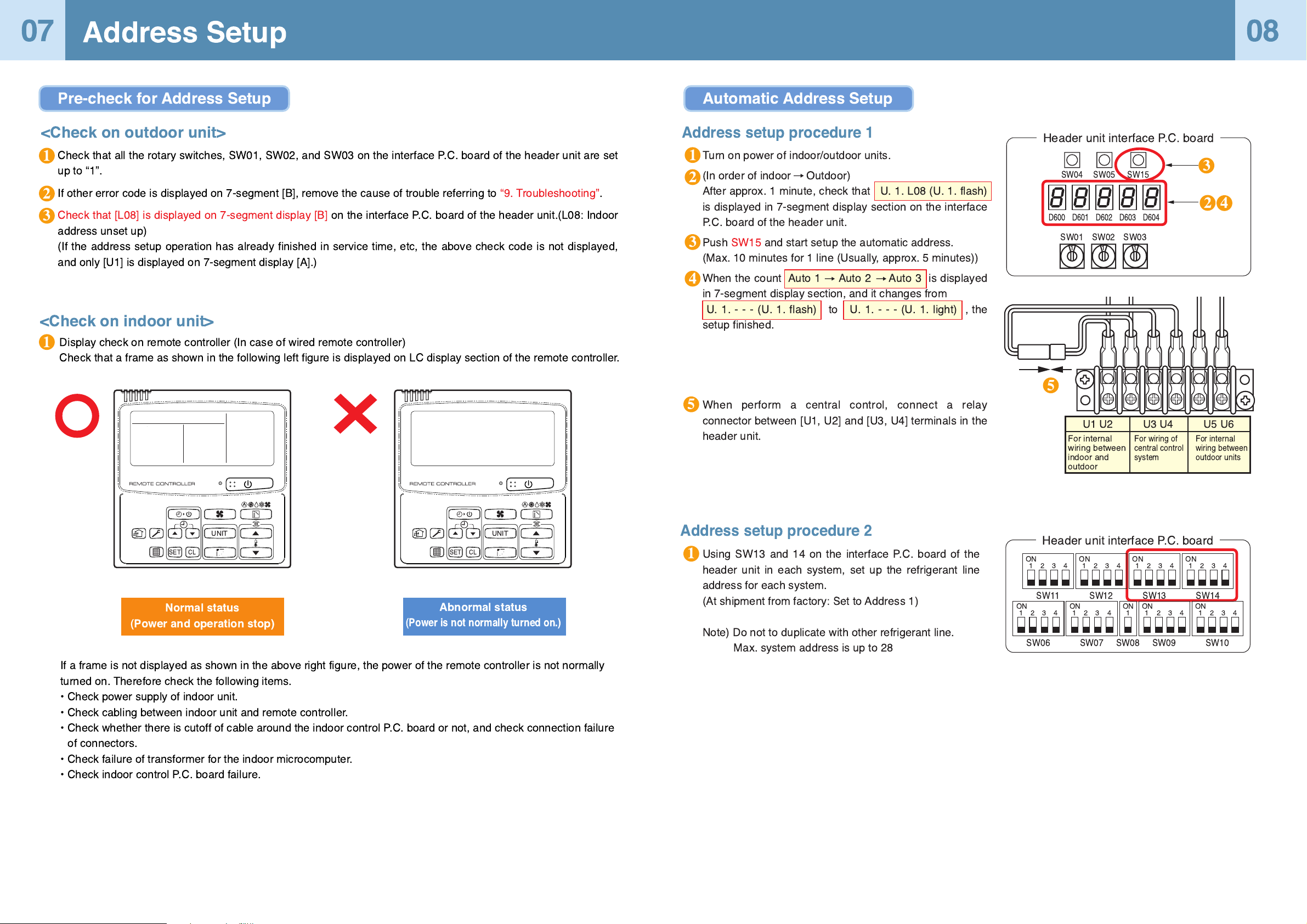
Check that all the rotary switches, SW01, SW02, and SW03 on the interface P.C. board of the header unit are set
up to Ò1Ó.
If other error code is displayed on 7-segment [B], remove the cause of trouble referring to Ò9. TroubleshootingÓ.
Check that [L08] is displayed on 7-segment display [B] on the interface P.C. board of the header unit.(L08: Indoor
address unset up)
(If the address setup operation has already finished in service time, etc, the above check code is not displayed,
and only [U1] is displayed on 7-segment display [A].)
<Check on outdoor unit>
Display check on remote controller (In case of wired remote controller)
Check that a frame as shown in the following left figure is displayed on LC display section of the remote controller.
<Check on indoor unit>
1
1
3
2
1
3
4
2
1
5
5
If a frame is not displayed as shown in the above right figure, the power of the remote controller is not normally
turned on. Therefore check the following items.
¥ Check power supply of indoor unit.
¥ Check cabling between indoor unit and remote controller.
¥ Check whether there is cutoff of cable around the indoor control P.C. board or not, and check connection failure
of connectors.
¥ Check failure of transformer for the indoor microcomputer.
¥ Check indoor control P.C. board failure.
Abnormal status
(Power is not normally turned on.)
Normal status
(Power and operation stop)
Pre-check for Address Setup Automatic Address Setup
Turn on power of indoor/outdoor units.
(In order of indoor Outdoor)
After approx. 1 minute, check that U. 1. L08 (U. 1. flash)
is displayed in 7-segment display section on the interface
P.C. board of the header unit.
Push SW15 and start setup the automatic address.
(Max. 10 minutes for 1 line (Usually, approx. 5 minutes))
When the count Auto 1 Auto 2 Auto 3 is displayed
in 7-segment display section, and it changes from
U. 1. - - - (U. 1. flash) to U. 1.---(U.1.light) , the
setup finished.
When perform a central control, connect a relay
connector between [U1, U2] and [U3, U4] terminals in the
header unit.
Address setup procedure 1
Address setup procedure 2
Using SW13 and 14 on the interface P.C. board of the
header unit in each system, set up the refrigerant line
address for each system.
(At shipment from factory: Set to Address 1)
Note) Do not to duplicate with other refrigerant line.
Max. system address is up to 28
3
4
2
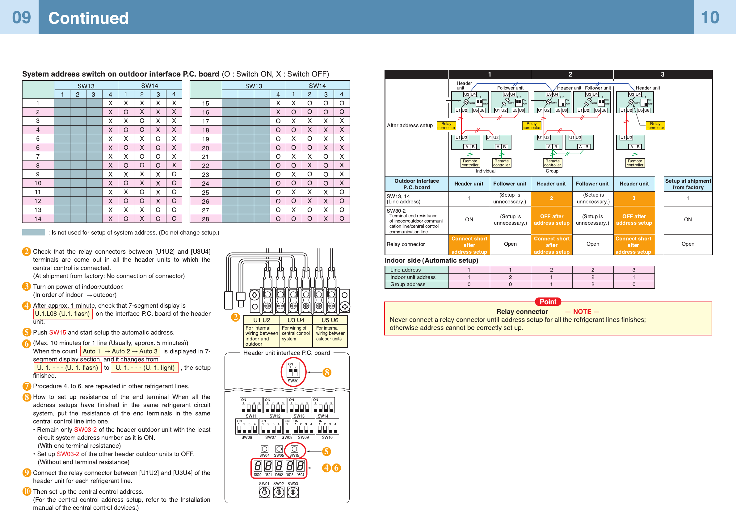
Ñ NOTE Ñ
Never connect a relay connector until address setup for all the refrigerant lines finishes;
otherwise address cannot be correctly set up.
After address setup
SW13, 14
(Line address)
SW30-2
Terminal-end resistance
of indoor/outdoor communi
cation line/central control
communication line
Relay connector
Indoor side (Automatic setup)
Line address
Indoor unit address
Group address
1
1
0
1
2
0
2
1
1
2
2
2
3
1
0
Connect short
after
address setup
Connect short
after
address setup
Connect short
after
address setup
Setup at shipment
from factory
U3 U4
U1 U2 U5 U6
U1 U2
A B
Header
unit
Header unit Header unit
Individual Group
Remote
controller
U3 U4
21
SW30
ON
OFF
U1 U2 U5 U6
U1 U2
A B
Follower unit
Remote
controller
Relay
connector
U3 U4
U1 U2 U5 U6
U1 U2
A B
Remote
controller
U3 U4
U1 U2 U5 U6
U1 U2
A B
Follower unit
U3 U4
U1 U2 U5 U6
U1 U2
A B
Remote
controller
Relay
connector
Relay
connector
Open
ON
1
2
12 3
3
1
Header unit Follower unit Follower unitHeader unit Header unit
ON
Open Open
OFF after
address setup
OFF after
address setup
(Setup is
unnecessary.)
(Setup is
unnecessary.)
(Setup is
unnecessary.)
(Setup is
unnecessary.)
Outdoor interface
P.C. board
21
SW30
ON
OFF
21
SW30 SW30
ON
OFF
21
SW30
ON
OFF
21
ON
OFF
Point
Relay connector
U1 U2
For internal
wiring between
indoor and
outdoor
U3 U4
For wiring of
central control
system
U5 U6
For internal
wiring between
outdoor units
SW04 SW05 SW15
D600 D601 D602 D603 D604
1
SW01
1
SW02
1
SW03
1 2 3 4
ON
SW11
1 2 3 4
ON
SW12
1 2 3 4
ON
SW06
1 2 3 4
ON
SW07
1 2 3 4
ON
SW09
1 2 3 4
ON
SW10
1
ON
SW08
1 2 3 4
ON
SW13
1 2 3 4
ON
SW14
12
ON
SW30
Header unit interface P.C. board
Continued
09
10
Check that the relay connectors between [U1U2] and [U3U4]
terminals are come out in all the header units to which the
central control is connected.
(At shipment from factory: No connection of connector)
Turn on power of indoor/outdoor.
(In order of indoor outdoor)
After approx. 1 minute, check that 7-segment display is
U.1.L08 (U.1. flash) on the interface P.C. board of the header
unit.
Push SW15 and start setup the automatic address.
(Max. 10 minutes for 1 line (Usually, approx. 5 minutes))
When the count Auto 1 Auto 2 Auto 3 is displayed in 7-
segment display section, and it changes from
U.1.---(U.1.flash) to U. 1.---(U.1.light) , the setup
finished.
Procedure 4. to 6. are repeated in other refrigerant lines.
How to set up resistance of the end terminal When all the
address setups have finished in the same refrigerant circuit
system, put the resistance of the end terminals in the same
central control line into one.
¥ Remain only SW03-2 of the header outdoor unit with the least
circuit system address number as it is ON.
(With end terminal resistance)
¥ Set up SW03-2 of the other header outdoor units to OFF.
(Without end terminal resistance)
Connect the relay connector between [U1U2] and [U3U4] of the
header unit for each refrigerant line.
Then set up the central control address.
(For the central control address setup, refer to the Installation
manual of the central control devices.)
1
2
3
4
5
6
7
8
9
10
11
12
13
14
SW13
4
X
X
X
X
X
X
X
X
X
X
X
X
X
X
12 3
SW14
1
X
O
X
O
X
O
X
O
X
O
X
O
X
O
2
X
X
O
O
X
X
O
O
X
X
O
O
X
X
3
X
X
X
X
O
O
O
O
X
X
X
X
O
O
4
X
X
X
X
X
X
X
X
O
O
O
O
O
O
15
16
17
18
19
20
21
22
23
24
25
26
27
28
SW13
4
X
X
O
O
O
O
O
O
O
O
O
O
O
O
SW14
1
X
O
X
O
X
O
X
O
X
O
X
O
X
O
2
O
O
X
X
O
O
X
X
O
O
X
X
O
O
3
O
O
X
X
X
X
O
O
O
O
X
X
X
X
4
O
O
X
X
X
X
X
X
X
X
O
O
O
O
System address switch on outdoor interface P.C. board
(O : Switch ON, X : Switch OFF)
: Is not used for setup of system address. (Do not change setup.)
5
3
4
7
8
9
10
8
6
2
2
5
4 6
 Loading...