


FILE NO. A04-002
INSTALLATION MANUAL
R410A
Heat RecoveryType
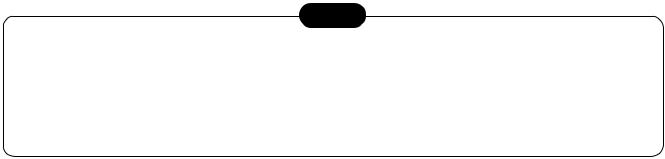
Indoor Unit
<4-way Air Discharge Cassette Type>
MMU-AP0091H, AP0121H, AP0151H, MMU-AP0181H, AP0241H, AP0271H, MMU-AP0301H, AP0361H, AP0481H MMU-AP0561H
<2-way Air Discharge Cassette Type>
MMU-AP0071WH, AP0091WH, AP0121WH, MMU-AP0151WH, AP0181WH, AP0241WH, MMU-AP0271WH, AP0301WH, AP0481WH*
* CHINA market only
<1-way Air Discharge Cassette Type>
MMU-AP0071YH, AP0091YH, AP0121YH, MMU-AP0151SH, AP0181SH, AP0241SH
<Concealed Duct Standard Type>
MMD-AP0071BH, AP0091BH, AP0121BH, MMD-AP0151BH, AP0181BH, AP0241BH, MMD-AP0271BH, AP0301BH, AP0361BH, MMD-AP0481BH, AP0561BH
<Concealed Duct High Static Pressure Type>
MMD-AP0181H, AP0241H, AP0271H, MMD-AP0361H, AP0481H
<Under Ceiling Type>
MMC-AP0151H, AP0181H, AP0241H, MMC-AP0271H, AP0361H, AP0481H
<High Wall Type>
MMK-AP0071H, AP0091H, AP0121H, MMK-AP0151H, AP0181H, AP0241H
<Floor Standing Cabinet Type>
MML-AP0071H, AP0091H, AP0121H, MML-AP0151H, AP0181H, AP0241H
<Floor Standing Concealed Type>
MML-AP0071BH, AP0091BH, AP0121BH, MML-AP0151BH, AP0181BH, AP0241BH
<Floor Standing Type>
MMF-AP0151H, AP0181H, AP0241H MMF-AP0271H, AP0361H, AP0481H MMF-AP0561H
Outdoor Unit
<Inverter Unit>
MMY-MAP0801FT8 MMY-MAP1001FT8 MMY-MAP1201FT8
FS unit
RBM-Y1121FE
RBM-Y1801FE
PRINTED IN JAPAN, Aug, 2004 ToMo

WARNINGS ON REFRIGERANT LEAKAGE
Check of Concentration Limit
The room in which the air conditioner is to be installed requires a design that in the event of refrigerant gas leaking out, its concentration will not exceed a set limit.
The refrigerant R410A which is used in the air conditioner is safe, without the toxicity or combustibility of ammonia, and is not restricted by laws to be imposed which protect the ozone layer. However, since it contains more than air, it poses the risk of suffocation if its concentration should rise excessively. Suffocation from leakage of R410A is almost non-existent. With the recent increase in the number of high concentration buildings, however, the installation of multi air conditioner systems is on the increase because of the need for effective use of floor space, individual control, energy conservation by curtailing heat and carrying power etc.
Most importantly, the multi air conditioner system is able to replenish a large amount of refrigerant compared with conventional individual air conditioners. If a single unit of the multi conditioner system is to be installed in a small room, select a suitable model and installation procedure so that if the refrigerant accidentally leaks out, its concentration does not reach the limit (and in the event of an emergency, measures can be made before injury can occur).
In a room where the concentration may exceed the limit, create an opening with adjacent rooms, or install mechanical ventilation combined with a gas leak detection device.
The concentration is as given below.
Total amount of refrigerant (kg)
Min. volume of the indoor unit installed room (m³) ≤ Concentration limit (kg/m³)
The concentration limit of R410A which is used in multi air conditioners is 0.3kg/m³.
NOTE 1 :
If there are 2 or more refrigerating systems in a single refrigerating device, the amounts of refrigerant should be as charged in each independent device.
Outdoor unit
e.g., charged
amount (10kg) 
 e.g.,
e.g.,
charged amount (15kg)
Room A Room B Room C Room D Room E Room F
Indoor unit
For the amount of charge in this example:
The possible amount of leaked refrigerant gas in rooms A, B and C is 10kg.
The possible amount of leaked refrigerant gas in rooms D, E and F is 15kg.
Important
NOTE : 2
The standards for minimum room volume are as follows.
(1) No partition (shaded portion)
(2)When there is an effective opening with the adjacent room for ventilation of leaking refrigerant gas (opening without a door, or an opening 0.15% or larger than the respective floor spaces at the top or bottom of the door).
Outdoor unit
 Refrigerant piping

 Indoor unit
(3)If an indoor unit is installed in each partitioned room and the refrigerant tubing is interconnected, the smallest room of course becomes the object. But when a mechanical ventilation is installed interlocked with a gas leakage detector in the smallest room where the density limit is exceeded, the volume of the next smallest room becomes the object.
|
|
Refrigerant piping |
|
|
|
Outdoor unit |
|
Very |
|
|
|
small |
|
Indoor unit |
|
room |
|
||
Small |
Medium |
Large room |
|
room |
room |
||
|
Mechanical ventilation device - Gas leak detector
NOTE 3 :
The minimum indoor floor area compared with the amount of refrigerant is roughly as follows: (When the ceiling is 2.7m high)
|
40 |
|
|
|
|
m² 35 |
Range below the |
|
|
|
|
density limit |
|
|
|
||
|
30 |
of 0.3 kg/m³ |
|
|
|
|
(countermeasures |
|
|
|
|
|
|
|
|
|
|
|
25 |
not needed) |
|
|
|
area |
|
|
|
|
|
20 |
|
|
|
|
|
floor |
15 |
|
Range above |
|
|
|
the density limit |
|
|||
indoor |
10 |
|
of 0.3 kg/m³ |
|
|
|
(countermeasures |
|
|||
|
|
needed) |
|
|
|
Min. |
5 |
|
|
|
|
|
|
|
|
||
0 |
|
|
|
|
|
|
10 |
20 |
30 |
|
|
|
|
|
|||
|
|
Total amount of refrigerant |
kg |
||
NOTE
A direct current motor is adopted for indoor fan motor in the Concealed Duct Standard Type air conditioner. Caused from its characteristics, a current limit works on the direct current motor. When replacing the highperformance filter or when opening the service panel, be sure to stop the fan. If an above action is executed during the fan operation, the protective control works to stop the unit operation, and the check code “P12” may be appear. However it is not a trouble. When the desired operation has finished, be sure to reset the system to clear “P12” error code using the electric leak breaker of the indoor unit. Then push the operation ON/OFF button of the remote controller to return to the usual operation.
|
CONTENTS |
|
1. |
SELECTING A LOCATION FOR INSTALLATION ..................................... |
4 |
2. |
SAFETY NOTES ......................................................................................... |
8 |
3. |
CHECK POINTS ......................................................................................... |
9 |
4. |
KEY POINTS OF AIR CONDITIONER INSTALLATION .......................... |
10 |
5. |
REFRIGERANT PIPE INSTALLATION .................................................... |
11 |
6. |
INDOOR UNIT INSTALLATION ................................................................ |
41 |
7. |
FLOW SELECTOR UNIT INSTALLATION ............................................... |
77 |
8. |
OUTDOOR UNIT INSTALLATION ............................................................ |
81 |
9. |
ELECTRIC WIRING .................................................................................. |
87 |
10. |
INDOOR UNIT TERMINAL BOARD PLACEMENT AND WIRING ......... |
102 |
11. |
DRAIN PIPE INSTALLATION ................................................................. |
107 |
12. |
ADJUSTMENT OF AIR DIRECTION...................................................... |
115 |
13. |
APPLIED CONTROL .............................................................................. |
119 |
14. |
ADDRESS SETUP.................................................................................. |
123 |
15. |
TEST OPERATION ................................................................................. |
136 |
16. |
SUPPORT FUNCTION IN TEST OPERATION ....................................... |
143 |
17. |
TROUBLESHOOTING ............................................................................ |
165 |
18. |
AIR SPEED CHARACTERISTICS.......................................................... |
170 |
19. |
FAN CHARACTERISTICS...................................................................... |
175 |

CAUTION New Refrigerant Air Conditioner Installation
•THIS AIR CONDITIONER ADOPTS THE NEW HFC REFRIGERANT (R410A) WHICH DOES NOT DESTROY OZONE LAYER.
The characteristics of R410A refrigerant are ; easy to absorb water, oxidizing membrane or oil, and its pressure is approx. 1.6 times higher than that of refrigerant R22. Accompanied with the new refrigerant, refrigerating oil has also been changed. Therefore, during installation work, be sure that water, dust, former refrigerant, or refrigerating oil does not enter the refrigerating cycle.
To prevent charging an incorrect refrigerant and refrigerating oil, the sizes of connecting sections of charging port of the main unit and installation tools are charged from those for the conventional refrigerant.
Accordingly the exclusive tools are required for the new refrigerant (R410A).
For connecting pipes, use new and clean piping designed for R410A, and please care so that water or dust does not enter. Moreover, do not use the existing piping because there are problems with pressureresistance force and impurity in it.
1. SELECTING A LOCATION FOR INSTALLATION
 WARNING
Install the air conditioner certainly at a location to sufficiently withstand the weight.
If the strength is insufficient, the unit may fall down resulting in human injury.
Perform a specified installation work to guard against a great wind such as typhoon or an earth quake.
An incomplete installation can cause accidents by the units failing and dropping.
The following models must be installed at height 2.5m or more from the floor. (Concealed type duct type and cassette type air conditioners)
If you insert your hands or others directly into the unit while the air conditioner operates, it is dangerous because you may contact with revolving fan or active electricity.
Installation Location Selection for Outdoor unit
Obtain permission from the customer to install the unit in a location that satisfies the following requirements :
•A location that permits level installation of the unit.
•A location that provides enough space to service the unit safety
•A location where water draining from the unit will not pose a problem
Avoid installing in the following places.
•Place exposed to air with high salt content (seaside area), or place exposed to large quantities of sulfide gas (hot spring). (Should the unit be used in these places, special protective measures are needed.)
•Place exposed to oil, vapor, oil smoke or corrosive gas.
•Place where organic solvent is used nearby.
•Place close to a machine generating high frequency.
•Place where the discharged air blows directly into the window of the neighboring house. (For outdoor unit)
•Place where noise of the outdoor unit is easily transmitted.
(When installing the air conditioner on the boundary with the neighbor, pay due attention to the level of noise.)
•Place with poor ventilation.
(Especially in Concealed duct type indoor unit, before air ducting work, check whether value of air volume, static pressure and duct resistance are correct.)
4

Equipments
1. Outdoor units
Corresponding HP |
|
|
|
|
|
|
|
|
|
Inverter unit |
|
|
|
|
Appearance |
|
|||
|
|
|
|
|
|
|
|
|
|
|
|
|
|
|
|
||||
|
|
|
|
8 HP |
|
|
|
|
10 HP |
|
12 HP |
|
|
|
|||||
|
|
|
|
|
|
|
|
|
|
|
|
|
|
|
|
||||
|
|
|
|
|
|
|
|
|
|
|
|
|
|
|
|
|
|
|
|
Model name |
MMY- |
|
MAP0801FT8 |
|
|
MAP1001FT8 |
|
MAP1201FT8 |
|
|
|
|
|||||||
|
|
|
|
|
|
|
|
|
|
|
|
|
|
|
|
|
|
|
|
Cooling capacity (kW) |
|
|
|
|
22.4 |
|
|
|
28.0 |
|
33.5 |
|
|
|
|
|
|||
|
|
|
|
|
|
|
|
|
|
|
|
|
|
|
|
|
|
|
|
Heating capacity (kW) |
|
|
|
|
25.0 |
|
|
|
31.5 |
|
35.5 |
|
|
|
|
|
|||
|
|
|
|
|
|
|
|
|
|
|
|
|
|
|
|
|
|
|
|
|
|
|
|
|
|
|
|
|
|
|
|
|
|
|
|
||||
HP |
Model name |
|
No. of |
|
Inverter 8HP |
Used |
Inverter 10HP |
Used |
Inverter 12HP |
|
Used |
||||||||
(Capacity code) |
MMY- |
combined units |
|
|
MMY- |
Q’ty |
|
MMY- |
Q’ty |
MMY- |
|
Q’ty |
|||||||
|
|
|
|
|
|
|
|
|
|
|
|
|
|
|
|
|
|
||
8 HP ( 8) |
MAP0801HT8 |
|
1 |
|
MAP0801FT8 |
1 |
|
|
|
|
|
|
|
||||||
|
|
|
|
|
|
|
|
|
|
|
|
|
|
|
|
|
|
|
|
10 HP (10) |
MAP1001HT8 |
|
1 |
|
|
|
|
|
|
|
MAP1001FT8 |
1 |
|
|
|
|
|||
|
|
|
|
|
|
|
|
|
|
|
|
|
|
|
|
|
|
|
|
12 HP (12) |
MAP1201HT8 |
|
1 |
|
|
|
|
|
|
|
|
|
|
|
MAP1201FT8 |
|
1 |
||
|
|
|
|
|
|
|
|
|
|
|
|
|
|
|
|
|
|
||
Allocation atandard of model name |
|
|
|
|
|
|
|
|
|
|
|
|
|
||||||
MMY– M |
AP |
|
|
F |
T |
8 |
|
|
|
|
|
|
|
|
|
|
|
||
|
|
|
|
|
|
|
|
|
|
|
Power supply specifications, 3Ø 380–415 V, 50Hz ....... 8 |
||||||||
|
|
|
|
|
|
|
|
|
|
|
|||||||||
|
|
|
|
|
|
|
|
|
|
|
T : Capacity variable unit |
|
|
|
|
|
|||
F : Heat recovery
Development series No.
Capacity rank HP x 10
New refrigerant R410A
M : Single module unit, No mark : Combined Model name
Modular Multi
2. FS units (Flow selector units)
Model name |
Inverter unit |
Appearance |
|
|
|
RBM-Y1121FE |
Capacity rank for indoor unit : Type 007 to 030 |
|
|
|
|
RBM-Y1801FE |
Capacity rank for indoor unit : Type 036 to 056 |
|
|
|
|
Accessory part : Connection cable kit (RBC-CBK15FE), up to 15m.
5
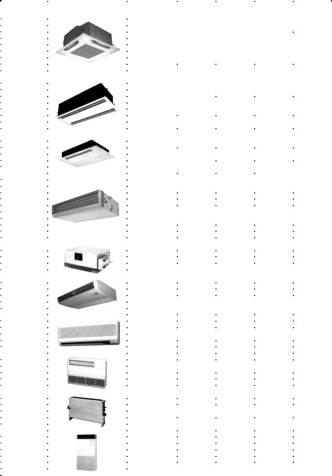
3. Indoor units
Type |
Appearance |
Model name |
Capacity rank |
Capacity code |
Cooling |
Heating |
|
capacity (kW) |
capacity (kW) |
||||||
|
|
|
|
|
|||
|
|
MMU-AP0091H |
009 type |
1 |
2.8 |
3.2 |
|
|
|
MMU-AP0121H |
012 type |
1.25 |
3.6 |
4.0 |
|
|
|
MMU-AP0151H |
015 type |
1.7 |
4.5 |
5.0 |
|
|
|
MMU-AP0181H |
018 type |
2 |
5.6 |
6.3 |
|
4-way Air Discharge |
|
MMU-AP0241H |
024 type |
2.5 |
7.1 |
8.0 |
|
Cassette Type |
|
MMU-AP0271H |
027 type |
3 |
8.0 |
9.0 |
|
|
|
MMU-AP0301H |
030 type |
3.2 |
9.0 |
10.0 |
|
|
|
MMU-AP0361H |
036 type |
4 |
11.2 |
12.5 |
|
|
|
MMU-AP0481H |
048 type |
5 |
14.0 |
16.0 |
|
|
|
MMU-AP0561H |
056 type |
6 |
16.0 |
18.0 |
|
|
|
MMU-AP0071WH |
007 type |
0.8 |
2.2 |
2.5 |
|
|
|
MMU-AP0091WH |
009 type |
1 |
2.8 |
3.2 |
|
|
|
MMU-AP0121WH |
012 type |
1.25 |
3.6 |
4.0 |
|
2-way Air Discharge |
|
MMU-AP0151WH |
015 type |
1.7 |
4.5 |
5.0 |
|
|
MMU-AP0181WH |
018 type |
2 |
5.6 |
6.3 |
||
Cassette Type |
|
||||||
|
MMU-AP0241WH |
024 type |
2.5 |
7.1 |
8.0 |
||
|
|
||||||
|
|
MMU-AP0271WH |
|
|
|
|
|
|
|
027 type |
3 |
8.0 |
9.0 |
||
|
|
MMU-AP0301WH |
030 type |
3.2 |
9.0 |
10.0 |
|
|
|
MMU-AP0481WH*1) |
048 type |
5 |
14.0 |
16.0 |
|
|
|
MMU-AP0071YH |
007 type |
0.8 |
2.2 |
2.5 |
|
|
|
MMU-AP0091YH |
009 type |
1 |
2.8 |
3.2 |
|
|
|
MMU-AP0121YH |
|
|
|
|
|
1-way Air Discharge |
|
012 type |
1.25 |
3.6 |
4.0 |
||
Cassette Type |
|
MMU-AP0151SH |
015 type |
1.7 |
4.5 |
5.0 |
|
|
|
MMU-AP0181SH |
018 type |
2 |
5.6 |
6.3 |
|
|
|
MMU-AP0241SH |
024 type |
2.5 |
7.1 |
8.0 |
|
|
|
MMD-AP0071BH |
007 type |
0.8 |
2.2 |
2.5 |
|
|
|
MMD-AP0091BH |
009 type |
1 |
2.8 |
3.2 |
|
|
|
MMD-AP0121BH |
012 type |
1.25 |
3.6 |
4.0 |
|
|
|
MMD-AP0151BH |
|
|
|
|
|
|
|
015 type |
1.7 |
4.5 |
5.0 |
||
Concealed Duct |
|
MMD-AP0181BH |
018 type |
2 |
5.6 |
6.3 |
|
|
MMD-AP0241BH |
|
|
|
|
||
|
024 type |
2.5 |
7.1 |
8.0 |
|||
Standard Type |
|
||||||
|
MMD-AP0271BH |
027 type |
3 |
8.0 |
9.0 |
||
|
|
||||||
|
|
MMD-AP0301BH |
030 type |
3.2 |
9.0 |
10.0 |
|
|
|
MMD-AP0361BH |
|
|
|
|
|
|
|
036 type |
4 |
11.2 |
12.5 |
||
|
|
MMD-AP0481BH |
048 type |
5 |
14.0 |
16.0 |
|
|
|
MMD-AP0561BH |
|
|
|
|
|
|
|
056 type |
6 |
16.0 |
18.0 |
||
|
|
MMD-AP0181H |
018 type |
2 |
5.6 |
6.3 |
|
Concealed Duct |
|
MMD-AP0241H |
024 type |
2.5 |
7.1 |
8.0 |
|
|
|
MMD-AP0271H |
|
|
|
|
|
High Static |
|
027 type |
3 |
8.0 |
9.0 |
||
Pressure Type |
|
MMD-AP0361H |
036 type |
4 |
11.2 |
12.5 |
|
|
|
MMD-AP0481H |
048 type |
5 |
14.0 |
16.0 |
|
|
|
MMC-AP0151H |
015 type |
1.7 |
4.5 |
5.0 |
|
|
|
MMC-AP0181H |
018 type |
2 |
5.6 |
6.3 |
|
|
|
MMC-AP0241H |
|
|
|
|
|
Under Ceiling Type |
|
024 type |
2.5 |
7.1 |
8.0 |
||
|
MMC-AP0271H |
027 type |
3 |
8.0 |
9.0 |
||
|
|
||||||
|
|
MMC-AP0361H |
036 type |
4 |
11.2 |
12.5 |
|
|
|
MMC-AP0481H |
048 type |
5 |
14.0 |
16.0 |
|
|
|
MMK-AP0071H |
007 type |
0.8 |
2.2 |
2.5 |
|
|
|
MMK-AP0091H |
|
|
|
|
|
|
|
009 type |
1 |
2.8 |
3.2 |
||
High Wall Type |
|
MMK-AP0121H |
012 type |
1.25 |
3.6 |
4.0 |
|
|
MMK-AP0151H |
015 type |
1.7 |
4.5 |
5.0 |
||
|
|
||||||
|
|
MMK-AP0181H |
|
|
|
|
|
|
|
018 type |
2 |
5.6 |
6.3 |
||
|
|
MMK-AP0241H |
024 type |
2.5 |
7.1 |
8.0 |
|
|
|
MML-AP0071H |
|
|
|
|
|
|
|
007 type |
0.8 |
2.2 |
2.5 |
||
|
|
MML-AP0091H |
|
|
|
|
|
|
|
009 type |
1 |
2.8 |
3.2 |
||
Floor Standing |
|
MML-AP0121H |
012 type |
1.25 |
3.6 |
4.0 |
|
Cabinet Type |
|
MML-AP0151H |
015 type |
1.7 |
4.5 |
5.0 |
|
|
|
MML-AP0181H |
018 type |
2 |
5.6 |
6.3 |
|
|
|
MML-AP0241H |
|
|
|
|
|
|
|
024 type |
2.5 |
7.1 |
8.0 |
||
|
|
MML-AP0071BH |
007 type |
0.8 |
2.2 |
2.5 |
|
|
|
MML-AP0091BH |
009 type |
1 |
2.8 |
3.2 |
|
Floor Standing |
|
MML-AP0121BH |
012 type |
1.25 |
3.6 |
4.0 |
|
Concealed Type |
|
MML-AP0151BH |
015 type |
1.7 |
4.5 |
5.0 |
|
|
|
MML-AP0181BH |
|
|
|
|
|
|
|
018 type |
2 |
5.6 |
6.3 |
||
|
|
MML-AP0241BH |
024 type |
2.5 |
7.1 |
8.0 |
|
|
|
MMF-AP0151H |
015 type |
1.7 |
4.5 |
5.0 |
|
|
|
MMF-AP0181H |
018 type |
2 |
5.6 |
6.3 |
|
|
|
MMF-AP0241H |
024 type |
2.5 |
7.1 |
8.0 |
|
Floor Standing Type |
|
MMF-AP0271H |
027 type |
3 |
8.0 |
9.0 |
|
|
|
MMF-AP0361H |
036 type |
4 |
11.2 |
12.5 |
|
|
|
MMF-AP0481H |
048 type |
5 |
14.0 |
16.0 |
|
|
|
MMF-AP0561H |
056 type |
6 |
16.0 |
18.0 |
|
|
|
*1) China only |
|
|
|
|
6

Tools
Required Tools
The used refrigerating oil is changed, and mixing of oil may cause a trouble such as generation of sludge, clogging of capillary, etc. Accordingly, the tools to be used are classified into the following three types.
(1)Tools exclusive for R410A (Those which cannot be used for conventional refrigerant (R22))
(2)Tools exclusive for R410A, but can be also used for conventional refrigerant (R22)
(3)Tools commonly used for R410A and for conventional refrigerant (R22)
The table below shows the tools exclusive for R410A and their interchangeability.
Tools exclusive for R410A (The following tools for R410A are required.)
Tools whose specifications are changed for R410A and their interchangeability
|
|
|
|
R410A |
Conventional air |
|
|
|
|
air conditioner installation |
conditioner installation |
||
No. |
Used tool |
Usage |
|
|
|
|
Existence of |
|
Whether conventional |
Whether new equipment |
|||
|
|
|
|
|||
|
|
|
new equipment |
|
equipment can be |
can be used with |
|
|
|
for R410A |
|
used |
conventional refrigerant |
|
|
|
|
|
|
|
• |
Flare tool |
Pipe flaring |
Yes |
|
*(Note 1) |
¡ |
|
|
|
|
|
|
|
|
Copper pipe gauge for |
Flaring by conventional |
|
|
|
|
‚ |
adjusting projection |
flare tool |
Yes |
|
*(Note 1) |
*(Note 1) |
|
margin |
|
|
|
|
|
|
|
|
|
|
|
|
ƒ |
Torque wrench |
Connection of flare nut |
Yes |
|
× |
× |
„ |
Gauge manifold |
Evacuating, refrigerant |
Yes |
|
× |
× |
|
|
|
||||
|
|
charge, run check, etc. |
|
|||
… |
Charge hose |
|
|
|
|
|
|
|
|
|
|
||
|
|
|
|
|
|
|
† |
Vacuum pump adapter |
Vacuum evacuating |
Yes |
|
× |
¡ |
‡ |
Electronic balance for |
Refrigerant charge |
Yes |
|
Yes |
¡ |
|
refrigerant charging |
|
||||
|
|
|
|
|
|
|
|
|
|
|
|
|
|
ˆ |
Refrigerant cylinder |
Refrigerant charge |
Yes |
|
× |
× |
‰ |
Leakage detector |
Gas leakage check |
Yes |
|
× |
¡ |
Š |
Charging cylinder |
Refrigerant charge |
(Note 2) |
|
× |
× |
(Note 1) When flaring is carried out for R410A using the conventional flare tools, adjustment of projection margin is necessary. For this adjustment, a copper pipe gauge, etc. are necessary.
(Note 2) Charging cylinder for R410A is being currently developed.
General tools (Conventional tools can be used.)
In addition to the above exclusive tools, the following equipments which serve also for R22 are necessary as the general tools.
(1) |
Vacuum pump |
(4) Reamer |
(9) |
Hole core drill |
||
|
Use vacuum pump by |
(5) Pipe bender |
(10) |
Hexagon wrench |
||
|
attaching vacuum pump adapter. |
(6) |
Level vial |
|
(Opposite side 4mm) |
|
(2) |
Torque wrench |
|
|
|||
(7) |
Screwdriver (+, –) |
(11) |
Tape measure |
|||
|
|
|||||
(3) |
Pipe cutter |
|
|
|||
(8) |
Spanner or Monkey wrench |
(12) |
Metal saw |
|||
|
|
|||||
|
|
|
|
|||
Also prepare the following equipments for other installation method and run check.
(1) |
Clamp meter |
(3) |
Insulation resistance tester |
(2) |
Thermometer |
(4) |
Electroscope |
7

2. SAFETY NOTES
•Ensure that all Local, National and International regulations are satisfied.
•Read this “SAFETY NOTES” carefully before Installation.
•The precautions described below include the important items regarding safety. Observe them without fail.
•After the installation work, perform a trial operation to check for any problem.
Follow the Owner’s Manual to explain how to use and maintain the unit to the customer.
•Turn off the main power supply switch (or breaker) before the unit maintenance.
•Ask the customer to keep the Installation Manual together with the Owner’s Manual.
WARNING
•Ask an authorized dealer or qualified installation professional to install/maintain the air conditioner.
Inappropriate installation may result in water leakage, electric shock or fire.
•Turn off the main power supply switch or breaker before attempting any electrical work.
Make sure all power switches are off. Failure to do so may cause electric shock.
•Connect the connecting wire correctly.
If the connecting wire is connected in a wrong way, electric parts may be damaged.
•When moving the air conditioner for the installation into another place, be very careful not to enter any gaseous matter other than the specified refrigerant into the refrigeration cycle.
If air or any other gas is mixed in the refrigerant, the gas pressure in the refrigeration cycle becomes abnormally high and it as a result causes pipe burst and injuries on persons.
•Do not modify this unit by removing any of the safety guards or by by-passing any of the safety interlock switches.
•Exposure of unit to water or other moisture before installation may cause a short-circuit of electrical parts.
Do not store it in a wet basement or expose to rain or water.
•After unpacking the unit, examine it carefully if there are possible damage.
•Do not install in a place that might increase the vibration of the unit.
•To avoid personal injury (with sharp edges), be careful when handling parts.
•Perform installation work properly according to the Installation Manual.
Inappropriate installation may result in water leakage, electric shock or fire.
•When the air conditioner is installed in a small room, provide appropriate measures to ensure that the concentration of refrigerant leakage occur in the room does not exceed the critical level.
•Install the air conditioner securely in a location where the base can sustain the weight adequately.
•Perform the specified installation work to guard against an earthquake.
If the air conditioner is not installed appropriately, accidents may occur due to the falling unit.
•If refrigerant gas has leaked during the installation work, ventilate the room immediately.
If the leaked refrigerant gas comes in contact with fire, noxious gas may generate.
•After the installation work, confirm that refrigerant gas does not leak.
If refrigerant gas leaks into the room and flows near a fire source, such as a cooking range, noxious gas might generate.
•Electrical work must be performed by a qualified electrician in accordance with the Installation Manual. Make sure the air conditioner uses an exclusive power supply.
An insufficient power supply capacity or inappropriate installation may cause fire.
•Use the specified wires for wiring connect the terminals securely fix. To prevent external forces applied to the terminals from affecting the terminals.
•Conform to the regulations of the local electric company when wiring the power supply.
Inappropriate grounding may cause electric shock.
•Do not install the air conditioner in a location subject to a risk of exposure to a combustible gas.
If a combustible gas leaks, and stays around the unit, a fire may occur.
8

3. CHECK POINTS
Check before operation
•Turn on the main power switch 12 hours or more before starting the operation.
•Check whether earth wire is disconnected or out of place.
•Check that air filter is installed to the indoor unit.
Heating capacity
•For heating operation, a heat pump type which absorbs the outdoor heat and deliver the heat in the room is adopted. If the outdoor temperature lowers, the heating capacity decreases.
•When the outdoor temperature is low, common use with other heating devices is recommended.
Defrost operation in heating operation
•If frost is found on the outdoor unit during heating operation, the defrost operation starts automatically (for approx. 2 to 10 minutes) so as to increase the heating effect.
•During defrost operation, the fans of both indoor and outdoor units stop.
Protection for 3 minutes
•The outdoor unit does not operate for approx. 3 minutes after air conditioner has been immediately restarted after stop, or power switch has been turned on. This is to protect the system.
Main power failure
•If a power failure occurs during operation, all operations stop.
•When the power is turned on after power failure, the operation lamp of the remote controller flashes to notify.
•When restarting the operation, push ON/OFF button again.
Fan rotation of stopped unit
•While other indoor units operate, the fan on indoor units on “stand-by” rotates to protect the machine once per approx. 1 hour for several minutes.
Protective device (High pressure switch)
The high pressure switch operate the air conditioner automatically stops when excessive load is applied to the air conditioner. If the protective device works, the operation lamp keeps lit but the operation stops.
When the protective device works, “CHECK” characters in the remote controller display section flash. The protective device may work in the following cases.
Cooling
•When air inlet or outlet of the outdoor unit is closed.
•When strong wind blows continuously against air outlet of the outdoor unit.
Heating
•When much dust or dirt is excessively adhered to air filter of the indoor unit.
•When air outlet of the indoor unit is blocked.
NOTE
If the protective device works, turn off the main power switch, remove the cause, and then restart the operation.
Cooling/ heating operation of Multi system air conditioner
•When COOL or HEAT mode is fixed by the manager of the air conditioner, other operation than the set mode is
unavailable. If other operation than the set mode has been performed, [  PRE-HEAT] or [
  Operation ready] on the operation part goes on and the operation stops.
Operating temperature of Super HRM
•When outdoor temperature goes out of specified range, “ or
or  ” mark is indicated on the remote controller display and required operation will stop. “
 &
&  ” : When heating operation. “ ” : When cooling operation.
[Notice]
•This indication is not failure.
•When outdoor temperature goes back to specified range, “
 or
or  ” disappear and start normal operation.
•Operation stops because concurrent operation can not be kept in the condition of out of specification for Super HRM.
(Outdoor temp. (DB) < –5°C : Cooling, > 21°C : Heating)
•Do not use “Super HRM” for other than personal usage where the ambient temperature may go down below –5°C. (For example, OA equipment/Electric device/Food/Animals and plants/Art object)
Characteristics of heating operation
•Air does not blow out immediately after start of the operation. When the indoor heat exchanger has been heated after 3 to 5 minutes passed (differs according to temperature of indoor/outdoor temperature), hot air starts blowing.
•During operation, the outdoor unit may stop when outdoor temperature becomes high.
•When other indoor unit performs heating operation during fan operation, fan operation may be stopped temporarily to prevent discharge of hot air.
9

4. KEY POINTS OF AIR CONDITIONER INSTALLATION
In order to prevent problems before they arise, carefully read (1) the Installation Manual provided with the equipment, and (2) the Owner’s Manual before installing the air conditioner.
4-1. Flow of Air Conditioner Installation Work
[Step] |
[Key Points] |
|
|
|
|
(Prior to Installation) |
|
|
|
|
|
Determination of extent of installation work |
Clearly determine the extent of the installation work. |
|
|
|
|
|
Draft : |
|
Drafting of diagrams |
• Control wiring system diagram |
|
• Refrigerant line system diagram |
||
|
||
|
• Power wiring system diagram |
|
|
|
|
(Installation) |
|
|
|
|
|
Sleeve/insert installation |
Pay careful attention to the downward slope of the drain pipe. |
|
|
|
|
|
Be sure to check the name of the model in order to avoid any |
|
Indoor unit and flow selector unit installation |
installation mistakes. If the model has an installation pattern, attach |
|
the pattern to the ceiling to mark the position of the ceiling openings |
||
|
||
|
and to keep dust away. |
|
|
|
|
|
Make sure that the pipe system is dry, clean, and airtight. |
|
Refrigerant pipe installation |
When brazing pipes, blow out the system with nitrogen gas. |
|
|
Do not forget the system indications. |
|
|
|
|
(to outdoor outlet) |
|
|
|
|
|
Drain pipe installation |
Pipes should have downward slope (of at least 1/100). |
|
|
|
|
Duct installation |
Make sure the duct is large enough to carry the desired volume of air. |
|
Be careful not to make any errors in the external static pressure |
||
|
calculations. |
|
|
|
|
Insulation work |
Be especially careful to close off all gaps where connections are made |
|
to the indoor unit, and at joints in the branching kit. Do not forget the |
||
|
drain pipes. |
|
|
|
|
Electrical work |
Use two-core shielded wires for the control wires, and use separate |
|
power supplies for the indoor and outdoor units. For connecting the |
||
(control wires and power wires) |
flow selector unit, be sure to use the attached cable or connection |
|
|
cable kit sold separately. |
|
|
|
|
Various switch settings |
Set the switches correctly, as indicated in the control wiring system |
|
diagram. |
||
|
||
|
|
|
Outdoor unit base installation |
Make sure that the base is level. |
|
|
|
|
Outdoor unit installation |
Provide for adequate air flow and service space around the outdoor |
|
unit. Indicate the system names clearly. |
||
|
||
|
|
|
Outside circulation, refrigerant pipe installation |
From outside outlet to outdoor unit. |
|
|
|
|
Gas-leak test |
In the final test, the system must be pressurized at 3.73MPa |
|
(38kg/cm²G) for 24 hours with no decrease in pressure. |
||
|
||
|
|
|
Vacuum suction |
Use a vacuum pump with reverse flaw prevention adaptor with a large |
|
output volume and that can achieve a high level of vacuum. |
||
|
||
|
|
|
Addition of refrigerant |
Record the amount of refrigerant that was added to the system on |
|
both the outdoor unit and on the pre-test operation checklist. |
||
|
||
|
|
|
Ceiling panel installation |
Make sure that the ceiling panel is attached to the ceiling material |
|
tightly, with no gaps. |
||
|
||
|
|
|
Test operation and adjustment |
Operate the indoor units one by one, making sure that all wiring and |
|
pipes are connected correctly, and fill out the checklist. |
||
|
||
|
|
|
Owner’s Manual transfer |
Explain how to operate the system clearly and concisely. |
|
|
|
The procedure described above presents only the general sequence of steps; the sequence of steps may have to be altered according to the circumstances of any specific installation job.
10
5. REFRIGERANT PIPE INSTALLATION
5-1. Work Procedure
Flaring
Indoor unit |
|
Sizing |
|
Preliminary |
|
installation |
|
the pipes |
|
installation |
|
|
|
|
Nitrogen gas blow
|
Flushing |
|
Leak test |
|
Vacuum |
|
|
|
|||
|
|
|
suction |
||
|
|
||||
|
|
|
|
|
Brazing
5-2. Three Principles of Refrigerant Pipes
<Observe the three principles of refrigerant pipes>
|
|
Causes of Problems |
|
|
|
Preventing Problems |
|
|
||||||||
|
|
|
|
|
|
|
|
|
|
|
|
|
|
|
|
|
|
• |
Moisture (in the form of |
|
|
|
|
|
|
|
|
|
|
|
|
|
|
|
|
rainwater or water used during |
|
|
|
|
|
|
|
|
|
|
|
|
|
|
|
|
Careful |
|
|
|
|
|
|
|
|
|
|
|
|
||
Dry |
|
installation, for example) |
|
|
|
|
|
|
|
|
|
|
|
Vacuum |
|
|
|
|
|
|
|
|
|
|
|
|
|
|
|
||||
|
|
handling |
|
|
|
Flushing |
|
|
|
|
|
|||||
|
getting inside of the pipes |
|
|
|
|
|
|
|
|
suction |
|
|||||
|
|
|
of pipes |
|
|
|
|
|
|
|
|
|
|
|
||
|
• |
Moisture from condensation |
|
|
|
|
|
|
|
|
|
|
|
|
||
|
|
|
|
|
|
|
|
|
|
|
|
|
|
|||
|
|
|
|
|
|
|
|
|
|
|
|
|
|
|
||
|
|
|
|
|
|
|
|
|
|
|
|
|
|
|||
|
|
forming or seeping into the pipes |
|
|
|
|
|
|
|
|
|
|
|
|
|
|
|
|
|
|
|
|
|
|
|
|
|
|
|
|
|
|
|
|
• |
Oxidation inside pipes during |
|
|
|
|
|
|
|
|
|
|
|
|
|
|
|
Nitrogen gas blow |
|
|
|
|
|
|
|
|
|||||||
Clean |
|
brazing |
|
|
|
|
|
|
|
|
||||||
|
|
|
|
|
|
|
Flushing |
|
||||||||
• |
Dirt, dust, or foreign matter |
|
|
|
|
|
|
|
|
|
|
|
|
|
||
|
|
Careful handling of pipes |
|
|
|
|
|
|
|
|
||||||
|
|
getting inside pipes |
|
|
|
|
|
|
|
|
|
|||||
|
|
|
|
|
|
|
|
|
|
|
|
|
|
|
|
|
|
|
|
|
|
|
|
|
|
|
|
||||||
|
|
|
|
|
|
|
|
|
|
|
|
|
|
|
|
|
|
|
|
|
Use of suitable materials |
|
|
|
|
|
|
||||||
Air- |
• |
Poor brazing |
|
(copper pipes, solder, etc.) |
|
|
|
|
|
|||||||
|
|
|
|
|
|
|
||||||||||
|
|
|
|
|
|
|
|
|||||||||
|
Perform basic work |
|
|
|
|
Leak test |
|
|||||||||
tight |
• |
Poor flaring |
|
of brazing carefully |
|
|
|
|
|
|||||||
|
|
|
|
|
|
|
||||||||||
|
|
|
|
|
|
|
|
|
|
|
||||||
|
|
|
|
|
|
|
|
|
|
|
||||||
|
|
|
|
Perform basic work |
|
|
|
|
|
|
||||||
|
|
|
|
of flaring carefully |
|
|
|
|
|
|
||||||
|
|
|
|
|
|
|
|
|
|
|
|
|
|
|
|
|
<Three principles of refrigerant pipes>
Dry |
Clean |
Airtight |
Make sure there is no moisture |
Make sure there is no dirt |
Make sure the refrigerant |
inside of the pipes |
inside of the pipes |
does not leak |
Moisture |
Dirt |
Leak |
|
Not good |
Not good |
Not good |
11

5-3. Selecting the Refrigerant Line Material
•Refrigerant pipes
•Material: Phosphoric deoxidized seam-less pipe
•Capacity code of outdoor unit / indoor unit
•For each indoor unit, the capacity code is determined for every capacity rank.
•For each outdoor unit, the capacity code is determined for every capacity rank. The Max. number of the connectable indoor units and the total capacity code value of the indoor units are also determined.
|
Against the capacity code of the outdoor unit, the total capacity codes of the connectable indoor units differ |
|
|
according to the height difference between indoor units. |
|
|
• |
When the height difference between indoor units is 15m or less : Up to 135% of capacity code of outdoor unit |
|
|
* |
|
|
(* For 12HP system, up to 120%.) |
|
• |
When the height difference between indoor units is 15m or more : Up to 105% of capacity code of outdoor unit |
Table 1 |
Table 2 |
|
Capacity code |
|
Indoor unit |
|
|
capacity rank |
Equivalent to |
Equivalent to |
|
HP |
capacity |
|
|
|
007 type |
0.8 |
2.2 |
|
|
|
009 type |
1 |
2.8 |
|
|
|
012 type |
1.25 |
3.6 |
|
|
|
015 type |
1.7 |
4.5 |
|
|
|
018 type |
2 |
5.6 |
|
|
|
024 type |
2.5 |
7.1 |
|
|
|
027 type |
3 |
8 |
|
|
|
030 type |
3.2 |
9 |
|
|
|
036 type |
4 |
11.2 |
|
|
|
048 type |
5 |
14 |
|
|
|
056 type |
6 |
16 |
|
|
|
|
|
|
|
Total capacity code of connectable indoor units |
||||
|
Capacity code |
|
|
|
|
|
|
|
Outdoor unit |
|
|
No. of |
|
Min |
Max. |
||
model name |
|
|
indoor units |
|
|
|
|
|
|
Equivalent to |
Equivalent to |
|
Equivalent |
Equivalent |
Equivalent |
Equivalent |
|
|
HP |
capacity |
|
to HP |
|
to capacity |
to HP |
to capacity |
|
|
|
|
|
|
|
|
|
MMY-MAP0801FT8 |
8 |
22.4 |
13 |
5.6 |
|
15.7 |
10.8 |
30.2 |
|
|
|
|
|
|
|
|
|
MMY-MAP1001FT8 |
10 |
28.0 |
16 |
7.0 |
|
19.6 |
13.5 |
37.8 |
|
|
|
|
|
|
|
|
|
MMY-MAP1201FT8 |
12 |
33.5 |
16 |
8.4 |
|
23.5 |
14.4 |
40.3 |
|
|
|
|
|
|
|
|
|
Table 3
No. |
Piping parts |
Name |
|
|
Selection of pipe size |
|
|
Remarks |
|
|
|
|
|
|
|
|
|
|
|
|
|
• |
Outdoor unit |
Outdoor unit |
1) Connecting pipe outdoor unit |
|
|
|
Same to connecting |
|
||
|
|
main pipe |
|
|
|
|
|
|
pipe size of outdoor unit |
|
|
↓ |
|
|
Model name |
Suction gas side |
Discharge gas side |
Liquid side |
|
|
|
|
|
|
|
|
|
|
|
|
|
|
|
1st branching joint |
|
|
MMY-MAP0801FT8 |
Ø22.2 |
Ø19.1 |
Ø12.7 |
|
|
|
|
|
|
|
|
|
|
|
|
|
|
|
|
|
MMY-MAP1001 FT8 |
Ø22.2 |
Ø19.1 |
Ø12.7 |
|
|
|
|
|
|
|
|
|
|
|
||||
|
|
|
|
|
|
|
|
|
|
|
|
|
|
|
MMY-MAP1201 FT8 |
Ø28.6 |
Ø19.1 |
Ø12.7 |
|
|
|
‚ Branching section Branching pipe |
2) Pipe size between branching sections |
↓
Branching section
Total capacity codes of indoor units |
|
|
|
|
at downstream side |
Suction |
Discharge |
Liquid side |
|
|
|
|||
Equivalent to |
Equivalent |
gas side |
gas side |
|
capacity |
to HP |
|
|
|
|
|
|
|
|
Below 18.0 |
Below 6.4 |
Ø15.9 |
Ø12.7 |
Ø9.5 |
|
|
|
|
|
18.0 to below 34.0 |
6.4 to below 12.2 |
Ø22.2 |
Ø19.1 |
Ø12.7 |
|
|
|
|
|
34.0 to below 45.5 |
12.2 to below 16.2 |
Ø28.6 |
Ø22.2 |
Ø15.9 |
|
|
|
|
|
If exceeding the main pipe size, decide the size same to main pipe size.
When two pipes are used for the circuits exclusive to cooling, use pipes at liquid and suction gas sides.
Pipe size differs based on total capacity code value of indoor units at downstream side.
If the total value exceeds the capacity code of the outdoor unit, apply capacity code of the outdoor unit.
(See tables 1 and 2.)
12
No. |
Piping parts |
Name |
|
|
|
Selection of pipe size |
|
|
|
|
|
|
|
|
|
|
|
|
|
|
|
|
|
|
|
ƒ |
End branching |
Connecting pipe |
3) Pipe size between end branching section and flow selector unit |
|
|
|
|
|
||||
|
section |
of flow selector |
|
|
|
|
|
|
|
|
|
|
|
|
unit |
|
Total capacity codes of indoor units |
Suction |
Discharge |
|
|
|
|||
|
↓ |
|
|
at downstream side |
|
Liquid side |
|
|||||
|
|
|
|
|
|
|
gas side |
gas side |
|
|
|
|
|
Flow selector unit |
|
|
Equivalent to capacity |
Equivalent to HP |
|
|
|
||||
|
|
|
|
|
|
|
|
|
||||
|
|
|
|
|
|
|
|
|
|
|
|
|
|
|
|
Below 4.5 |
Below 1.7 |
Ø12.7 |
Ø9.5 |
|
Ø6.4 |
|
|||
|
|
|
|
|
|
|||||||
|
|
|
|
|
|
|
|
|
|
|
|
|
|
|
|
|
4.5 to below 18.0 |
1.7 to below 6.4 |
Ø15.9 |
Ø12.7 |
|
Ø9.5 |
|
||
|
|
|
|
|
|
|
|
|
|
|
|
|
|
|
|
|
|
|
|
|
|
|
|
||
„ |
Branching section |
Connecting pipe |
4) Connecting pipe size of indoor unit |
|
|
|
|
|
|
|||
|
or flow selector |
of indoor unit |
|
|
|
|
|
|
|
|
|
|
|
unit |
|
|
Capacity rank |
Gas side |
|
|
Liquid side |
|
|||
|
↓ |
|
|
007 to 012 type |
|
Real length: Below 15m |
Ø9.5 |
|
|
|
|
|
|
|
|
|
|
|
|
|
|
|
|
||
|
|
|
|
Real length: Over 15m |
Ø12.7 |
|
|
Ø6.4 |
|
|||
|
|
|
|
|
|
|
|
|||||
|
|
|
|
|
|
|
|
|
||||
|
Indoor unit |
|
|
|
|
|
|
|
|
|
|
|
|
|
|
015 to 018 type |
Ø12.7 |
|
|
|
|
|
|||
|
|
|
|
|
|
|
|
|
|
|||
|
|
|
|
024 to 056 type |
Ø15.9 |
|
|
Ø9.5 |
|
|||
|
|
|
|
|
|
|
|
|
|
|
|
|
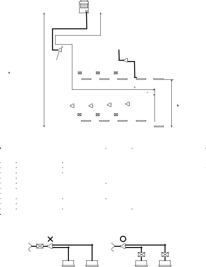
When pipe length between the end branching section and cooling-only indoor unit exceeds 15m, decide pipe size at gas side to the bigger one with Ø12.7.
… Branching section Branching header 5) Selection of branching joint/header |
|
|
|
|
||
of Y-shape |
|
|
|
|
|
|
branching joint |
|
Total capacity codes of indoor units |
Model name |
RBM- |
||
|
|
Equivalent to |
Equivalent to HP |
For 3 |
|
For 2 |
|
|
capacity |
|
pipes piping |
|
pipes piping |
|
|
|
|
|
|
|
|
Y-shape branching joint |
Below 18.0 |
Below 6.4 |
BY53FE |
|
BY53E |
|
1, 2 |
18.0 to below 40.0 |
6.4 to below 14.2 |
BY103FE |
|
BY103E |
|
|
|
||||
|
|
|
|
|
|
|
|
Branching header |
Below 40.0 |
Below 14.2 |
HY1043FE |
|
HY1043E |
|
1, 2, 3 |
Below 40.0 |
Below 14.2 |
HY1083FE |
|
HY1083E |
|
|
|
||||
|
|
|
|
|
|
|
1 For branching pipe of the 1st branching section, select one by the outdoor unit capacity code.
2 When total capacity codes of indoor units exceed capacity code of outdoor unit, select one by capacity code of outdoor unit.
3 1 line after header branching is connectable up to total maximum capacity codes 6.0 (Equivalent to HP).
† Branching |
Flow selector unit 6) Selection of flow selector unit |
|
|
|
|
|
|
|
|
Model name |
Capacity rank of connectable indoor unit |
|
|
|
|
|
|
RBM-Y1121FE |
007 to 030 type |
|
|
|
|
|
|
RBM-Y1801FE |
036 to 056 type |
|
|
|
|
Confirm also Installation Manual of flow selector unit.
|
|
|
3 piping |
|
2 piping |
|
|
|
(Liquld,discharge gas,suction gas) |
(Liquld, gas pipe) |
|||
Outdoor unit |
|
Outdoor unit to FS unit |
|
FS unit to indoor unit |
||
|
|
|
Branching section indoor unit |
|||
|
|
|
|
|
||
1 Main piping |
2 |
|
5 Header branching |
|
|
|
|
|
|
|
|
|
|
1st branching |
|
|
5 Y-shape branching joint |
|||
|
|
2 |
|
|
|
|
section |
|
|
|
|
|
|
|
|
|
|
|
|
|
|
3 |
3 |
3 |
|
|
|
FS unit |
6 |
6 |
6 |
|
|
|
2 |
4 |
4 |
4 |
4 |
|
4 |
|
Indoor unit |
|
< Cooling only > |
< Cooling only > |
||
|
|
|
||||
|
2 |
2 |
2 |
|
|
|
|
3 |
3 |
3 |
|
|
|
FS unit |
6 |
6 |
6 |
|
|
|
|
4 |
4 |
4 |
4 |
4 |
|
|
|
Indoor unit |
|
< Cooling only > |
< Cooling only > |
|
13
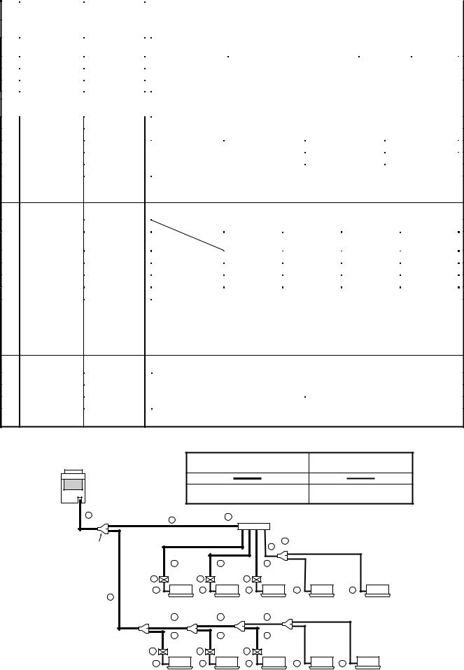
5-4. Allowable Length/Height Difference of Refrigerant Piping
Outdoor unit
• System restrictions
|
|
|
|
|
|
|
|
|
|
|
|
|
|
|
|
|
|
|
|
|
|
|
|
|
|
|
|
|
|
|
|
|
|
|
|
|
|
|
|
|
|
|
|
|
|
|
|
|
|
|
|
|
|
|
|
|
|
|
|
|
|
|
|
|
|
|
|
|
|
|
|
|
|
|
|
|
|
|
|
|
|
|
|
Max. capacity of |
|
H2 ≤ |
15m |
135% |
|||||||||
|
|
|
|
|
|
|
|
|
|
|
|
|
|
|
|
|
|
|
|
|
|
|
|
|
|
|
|
|
|
|
|
|
|
|
|
|
|
|
|
|||||||||
|
Main |
|
|
|
|
|
|
|
|
|
|
|
|
|
|
|
|
|
combined indoor unit |
|
H2 > 15m |
105% |
||||||||||||||||||||||||||
|
piping L1 |
|
|
|
|
|
|
|
|
|
|
|
|
|
|
|
|
|
|
|
|
|
|
|
|
|
|
|
||||||||||||||||||||
|
|
|
|
|
|
|
|
|
|
|
|
|
|
|
|
|
|
|
|
|
|
|
|
|
|
|
|
|
|
|
|
|||||||||||||||||
|
|
|
|
|
|
|
|
|
|
|
|
|
|
|
|
|
|
|
|
|
|
|
|
|
|
|
|
|
|
|
|
|
|
|
|
|
|
|||||||||||
|
|
|
|
|
|
|
|
|
|
|
|
|
|
|
|
|
|
|
|
|
|
|
|
|
|
|
|
|
|
|
|
|
|
For 12HP system, up to 120% |
|
|||||||||||||
|
|
|
|
|
|
|
|
|
|
|
|
|
|
|
|
|
|
|
|
|
|
|
|
|
Branching |
|
|
|
|
|
|
|
|
|
|
|
|
|
|
|||||||||
|
|
|
|
|
|
|
|
|
|
|
|
Branching piping L2 |
header |
|
|
|
|
|
|
|
|
|
|
|
|
|
|
|||||||||||||||||||||
|
|
|
|
|
|
|
|
|
|
|
|
|
|
|
|
|
|
|
|
|
|
|
|
|
|
|
|
|
|
|
|
|
|
|
|
|
|
|
||||||||||
|
|
|
|
|
|
|
|
|
|
|
|
|
|
|
|
|
|
|
|
|
|
|
|
|
|
|
|
|
|
|
|
|
|
|
|
|
|
|
||||||||||
|
|
|
|
|
|
Connecting piping of indoor unit |
|
|
|
|
|
|
L7 |
|
|
|
|
|
|
|
|
|
|
|
|
|
|
|||||||||||||||||||||
|
1st branching |
|
|
|
|
|
|
|
|
|
|
|
|
|
|
|
|
|
|
|
|
|
|
|
|
|
|
|
|
|
|
|
|
|
|
|
|
|
|
|
|
|
|
|
|
|
||
|
|
|
|
|
|
|
|
|
|
|
|
|
|
|
|
|
|
|
|
|
|
|
|
|
|
|
|
|
|
|
|
|
|
|
|
|
|
|
|
|
|
|
|
|
|
|||
|
section |
|
|
|
|
a |
|
|
|
b |
|
|
|
|
c |
|
|
|
|
|
|
|
|
|
|
|
|
|
|
|||||||||||||||||||
Height difference between outdoor |
|
|
|
|
|
|
|
|
|
|
|
|
|
|
|
|
|
|
|
|
|
|
|
|
|
|
|
|
|
|
|
|
||||||||||||||||
and indoor units |
|
|
L3 |
|
|
|
|
|
|
|
|
|
|
|
|
|
|
|
|
|
|
|
|
|
|
|
|
|
|
|
|
|
|
|
|
|
|
|
|
|
|
|||||||
H1 50m |
|
|
|
|
|
|
|
|
|
|
|
|
|
|
|
|
|
|
|
|
|
|
|
|
|
|
|
|
|
|
|
FS unit |
|
|
|
|
|
|
|
|
|
|
|
|
|
|
||
|
|
|
|
|
|
|
g |
|
|
|
|
|
|
|
h |
|
|
|
i |
|
|
|
|
|
|
|
j |
|
|
k |
|
|
|
|
|
|
|
|
||||||||||
|
|
|
|
|
|
|
|
|
|
|
|
|
|
|
|
|
|
|
|
|
|
|
||||||||||||||||||||||||||
|
|
|
|
|
|
|
|
|
|
|
|
|
|
|
|
|
|
|
|
|
Indoor unit |
|
|
|
|
|
|
|
|
|
|
< Cooling only > < Cooling only > |
|
|
||||||||||||||
|
|
|
|
|
|
|
Equivalent length corresponded to farthest piping L 125m |
|
|
|
|
|
|
|
|
|
||||||||||||||||||||||||||||||||
|
|
|
|
|
Equivalent length corresponded to farthest piping after 1st branching Li |
50m |
|
|
|
|
|
|||||||||||||||||||||||||||||||||||||
|
|
|
|
|
|
|
|
|
|
|
|
|
|
|
|
|
|
|
|
|
|
|
|
|
|
|
|
|
|
|
|
|
|
|
|
|
|
|
|
Height difference between |
||||||||
|
|
|
|
|
|
|
|
|
|
|
|
|
L4 |
|
|
|
L5 |
|
|
|
|
|
|
L6 |
|
|
|
|
|
|
|
|
|
|
||||||||||||||
|
|
|
|
|
|
|
|
|
|
|
|
|
|
|
|
|
|
|
|
|
|
|
|
|
|
|
|
|
|
|
|
|
|
|
|
|
|
|
|
|
|
|
|
|
indoor units |
|
||
|
|
|
|
|
|
|
|
|
|
|
|
|
|
|
|
|
|
|
|
|
|
|
|
|
|
|
|
|
|
|
|
|
|
|
|
|
|
|
|
p |
|
|
|
H2 |
35m |
|
||
|
|
|
|
|
|
|
|
|
|
|
d |
|
|
|
e |
|
|
|
|
|
f |
|
o |
|
|
|
|
|
|
|
|
|
|
|||||||||||||||
|
|
|
|
FS unit |
|
|
|
|
|
|
|
|
|
|
|
|
|
|
|
|
|
|
|
|
|
|
|
|
|
|
|
|
|
|
|
|
|
|
|
|
|
|
|
|
||||
|
|
|
|
|
|
|
|
|
|
|
|
|
|
|
|
|
|
|
|
|
|
|
|
|
|
|
|
|
|
|
|
|
|
|
|
|
|
|
|
|
|
|
|
|||||
|
|
|
|
|
|
|
l |
|
|
|
|
|
|
|
|
m |
|
|
|
|
|
|
n |
|
|
|
|
|
|
|
|
|
|
|
|
|
|
|
|
|
|
|
||||||
|
|
|
|
|
|
|
|
|
|
|
|
|
|
|
|
|
|
|
|
|
|
|
|
|
|
|
|
|
|
|
|
|
||||||||||||||||
|
|
|
|
|
|
|
|
|
|
|
|
|
|
|
|
|
|
|
|
|
|
|
|
|
|
|
|
|
|
|
|
|
|
|
|
< Cooling only > |
|
|
|
|
|
|
|
|
|
|||
|
|
|
|
|
|
|
|
|
|
|
|
|
|
|
|
|
|
|
|
|
|
|
|
|
|
|
|
|
|
|
|
|
|
|
|
|
|
|
|
|
|
|
|
|
||||
|
|
|
|
|
|
|
|
|
|
|
|
|
|
|
|
|
|
|
|
|
|
|
|
|
|
|
|
|
|
|
|
|
|
|
|
|
|
|
|
|
|
|
|
|
|
|
|
|
|
|
|
|
|
|
|
|
|
|
|
|
|
|
|
|
|
|
|
|
|
|
|
|
|
|
|
|
|
|
|
|
|
|
|
|
|
|
|
|
|
|
|
|
|
|
|
|
|
|
|
|
|
|
|
|
|
|
|
|
|
|
|
|
|
|
|
|
|
|
|
|
|
|
|
|
|
|
|
|
|
|
|
|
|
|
|
|
|
|
|
< Cooling only > |
|
|
||||
• Allowable length and height difference of refrigerant piping
|
|
|
Allowable value |
Piping section |
|
|
|
|
|
|
Total extension of pipe (Liquid pipe, real length) |
250 m |
L1 + L2 + L3 + L4+ L5 + L6 + L7 + a + b + c + |
|
|
d + e + f + g + h + i + j + k + l + m + n + o + p |
|||
|
|
|
|
|
|
|
|
|
|
|
Farthest piping length L (*1) |
Real length |
100 m |
L1 + L3 + L4 + L5 + L6 + p |
|
|
|
||
Pipe |
Equivalent length |
125 m |
||
Length |
Max. equivalent length of main piping |
85 m |
L1 |
|
|
|
|
|
|
|
Equivalent length of farthest piping from 1st branching Li (*1) |
50 m |
L3 + L4 + L5 + L6 + p |
|
|
Max. real length of indoor unit connecting piping |
30 m |
a + g, b + h, c + l, d + l, e + m, f + n, j, k, o, p |
|
|
|
|
|
|
|
Max. real length between FS unit and indoor unit (*2) |
15 m |
g, h, i, l, m, n |
|
|
Height between indoor |
Upper outdoor unit |
50 m |
—— |
Height |
and outdoor units H1 |
Lower outdoor unit |
30 m |
—— |
difference |
Height between indoor units H2 |
Upper outdoor unit |
35 m |
—— |
|
|
|
|
|
|
Lower outdoor unit |
15 m |
—— |
|
|
|
|||
*1 The farthest indoor unit from the 1st Branch to be named as (p).
*2 Attached connection cable can be used up to 5 m in pipe length between indoor and FS unit. When the pipe length between indoor and FS unit exceeds 5 m, be sure to use the connection cable kit (RBC-CBK15FE). (Sold separately)
FS unit
FS unit
|
|
|
|
|
|
|
Indoor unit |
|
Indoor unit |
||||
[NOTE] :
Don’t connect two or more indoor units to one FS unit. Arrange one indoor unit and one FS unit set to 1 by 1.
14

•Brazed couplings and special branches
•Use suitable parts for typical elbow couplings and socket couplings.
(Consider the size, material, thickness, etc.)
• Special branches
Use deoxidized parts sold separately.
Branching at indoor unit side
Branch header
Branching joint |
4 branching |
8 branching |
|
||
RBM-BY53E |
RBM-HY1043E |
RBM-HY1083E |
RBM-BY103E |
RBM-HY1043FE |
RBM-HY1083FE |
RBM-BY53FE |
|
|
RBM-BY103FE |
|
|
• Solder
Because only “copper-to-copper” connections are made in the multi type air conditioning system, use the hard solder “phosphor copper solder.”
15

5-5. Careful Handling
Careful handling is the most important step in preventing moisture, dirt, and dust from getting inside of the pipes. Moisture in pipes has caused major problems in numerous instances in the past. Therefore, it is important to be as careful as possible in order to prevent problems before they occur.
Pipe delivery and storage
When pipes are delivered, care should be taken to prevent it from becoming bent or deformed, and the ends of the pipes should be capped in order to prevent dirt, mud, rain, etc., from getting inside. Build a wooden frame to hold the pipes securely, and store the pipes in the specified location.
Delivery of copper pipes without caps to a work site is not acceptable.
|
|
Cap |
|
Frame for careful handling |
Careful handling on a pallet |
Pipe caps |
|
and to prevent rolling |
|||
|
|
The ends of all pipes must be sealed. The most reliable method is the “pinch method,” but the taping method can be selected in some circumstances.
Location |
Time for installation |
Careful handling method |
|
|
|
Outdoors |
One month or more |
Pinch method |
|
|
|
|
Less than one month |
Pinch or taping method |
|
|
|
Indoors |
Does not matter |
Pinch or taping method |
|
|
|
n Pinch method
Pinch the end of the copper pipe closed, and braze any opening closed.
n Taping method
Cover the end of the copper pipe with vinyl tape.
Copper pipe
Solder
Braze here
[Taping method]
Opening
Vinyl tape |
Flatten |
Fold over
Tape again
Copper pipe
16
CAUTIONS
|
|
GOOD |
NOT GOOD |
1) Do not allow dirt or moisture |
|
|
|
inside of the pipes. |
|
Dirt and moisture get inside |
|
• |
Keep the open ends of all pipes |
|
|
|
|
||
|
capped until all pipes have been |
Cap |
|
|
connected. |
|
|
|
|
|
|
• |
Pipe openings should face |
|
|
|
horizontally or downwards if at all |
|
Pipe |
|
possible. |
|
|
|
|
|
|
2) When passing a pipe through an |
Wall |
Cap or |
Wall |
|
opening in a wall, always keep |
plastic bag |
|||
|
|
|||
|
|
|
||
the end of the pipe capped. |
|
|
|
|
|
|
Rubber band |
Particles of |
|
|
|
the wall get |
||
|
|
|
||
|
|
|
inside the pipe |
3) Do not place pipes directly on |
Rubber |
Cap or |
|
|
band |
|
|
||
the ground. Do not scrape pipes |
|
|
plastic bag |
Dirt gets inside of pipe |
|
|
Do not allow |
||
on the ground. |
|
|
||
|
|
pipe to touch |
|
|
|
|
|
ground |
|
|
Ground |
Ground |
||
4) When deflashing (removing |
|
Pipe |
|
|
burrs from) a pipe, point the |
|
|
Burrs |
|
opening downwards so that no |
|
|
Deflasher |
|
scraps fall inside of the pipe. |
|
|
|
|
|
|
|
|
Scraps get inside of pipe |
5) When installing pipes on a rainy |
|
|
Cap or |
|
|
|
plastic bag |
|
|
day, always keep the ends of the |
|
|
Rain gets |
|
|
|
|
||
pipes capped. |
|
|
Rubber |
inside of pipe |
|
|
|
||
|
|
|
band |
|
|
Rain |
|
|
Rain |
17

5-6. Parts of Branching Header/Joint
Branching Header : RBM-HY1043E / HY1083E
Branching Joint : RBM-BY53E / BY103E
•Check the following parts in the package.
•For piping material and size of the refrigerant pipes, refer to the Installation Manual of the Air Conditioner.
NOTE : 1. |
All dimensions are in millimeters. In the following tables, ( ) indicates diameter of the indicated position, and |
|
|
others indicate diameter of the connecting pipe. |
|
2. |
Please connect pipe to the side with a projection of the socket. |
projection |
|
( 51 , 52 , 54 , 58 , 59 , 61 , 62 , 70 , 89 : without projection) |
Diameter of the |
|
connecting pipe |
|
|
|
|
|
|
socket |
Branching Header
NAME |
MODEL |
RBM-HY1043E |
RBM-HY1083E |
||||
Branching header |
Ø15.9 |
|
|
Ø15.9 |
|
|
|
|
|
|
|
|
|
||
gas side |
|
Ø22.2 |
|
|
Ø22.2 |
|
|
|
|
|
1pc |
|
1pc |
||
|
|
|
|
|
|
||
Branching header |
Ø9.5 |
|
|
Ø9.5 |
|
|
|
|
|
|
|
|
|
||
|
|
|
|
|
|
||
liquid side |
|
Ø15.9 |
|
|
Ø15.9 |
|
|
|
|
|
|
1pc |
|
|
1pc |
Heat insulator
(gas side/liquid side)
|
|
|
|
|
|
|
1pc each |
|
|
|
1pc each |
|
|
|
|
|
No. |
|
No. |
|
No. |
|
No. |
|
|
|
Liquid Gas |
side side |
|
14 |
Ø15.9 x (Ø22.2) 1pc |
06 |
Ø 9.5 x (Ø15.9) 4pcs |
14 |
Ø15.9 x (Ø22.2) 1pc |
06 |
Ø 9.5 x (Ø15.9) 8pcs |
|
Socket |
diameter of the |
18 |
Ø19.1 x (Ø22.2) 1pc |
09 |
Ø12.7 x (Ø15.9) 4pcs |
18 |
Ø19.1 x (Ø22.2) 1pc |
09 |
Ø12.7 x (Ø15.9) 8pcs |
|||
connected pipe |
70 |
Ø28.6 x (Ø22.2) 1pc |
|
|
70 |
Ø28.6 x (Ø22.2) 1pc |
|
|
||||
|
|
|
|
|
||||||||
) |
|
|
|
|
|
|
|
|
||||
( |
06 |
Ø 9.5 x (Ø15.9) 1pc |
01 |
Ø 6.4 x (Ø 9.5) 4pcs |
06 |
Ø 9.5 x (Ø15.9) 1ps |
01 |
Ø 6.4 x (Ø 9.5) 8pcs |
||||
external diameter |
||||||||||||
09 |
Ø12.7 x (Ø15.9) 1pc |
|
|
09 |
Ø12.7 x (Ø15.9) 1ps |
|
|
|||||
of socket |
|
|
|
|
||||||||
|
|
|
|
|
|
|
|
|||||
|
|
|
|
|
|
|
|
|
Outlet sealed pipe at gas side |
(Ø15.9) 1pc |
(Ø15.9) |
3pcs |
Header sealed pipe at liquid side |
(Ø15.9) 1pc |
(Ø15.9) |
1pc |
Outlet sealed pipe at liquid side |
(Ø 9.5) 1pc |
(Ø 9.5) 3pcs |
|
NAME |
|
MODEL |
|
RBM-BY53E |
|
|
RBM-BY103E |
|||||
|
|
|
|
|
|
|
Ø12.7 |
|
|
|
|
Ø19.1 |
|
|
Branching joint |
|
|
Ø15.9 |
|
|
|
|
Ø22.2 |
|
|
||
|
gas side |
|
|
|
|
|
|
|
|
||||
|
|
|
|
|
|
Ø12.7 |
|
|
|
Ø19.1 |
|
||
|
|
|
|
|
|
|
|
|
1pc |
|
|
|
1pc |
Joint |
Branching joint |
|
|
Ø12.7 |
|
Ø9.5 |
|
|
Ø15.9 |
|
Ø12.7 |
||
|
|
|
|
Ø9.5 |
|
|
|
|
Ø12.7 |
||||
liquid side |
|
|
|
|
|
|
|
|
|||||
|
|
|
|
|
|
|
|
|
|
||||
|
|
|
|
|
|
|
|
1pc |
|
|
|
1pc |
|
Branching |
|
|
|
|
|
|
|
|
|
|
|
||
Heat insulator |
|
|
|
|
|
|
|
|
|
|
|||
(gas side/liquid side) |
|
|
|
|
1pc each |
|
|
|
1pc each |
||||
|
|
|
|
|
|
|
|
|
|
|
|||
|
|
|
|
No. |
|
No. |
|
|
No. |
|
No. |
|
|
|
side |
diameter of the |
09 |
Ø12.7 x (Ø15.9) 1pc |
05 |
Ø 9.5 x (Ø12.7) 2pcs |
18 |
Ø19.1 x (Ø22.2) 1pc |
07 |
Ø 9.5 x (Ø19.1) 1pc |
|||
|
51 |
Ø19.1 x (Ø15.9) 1pc |
54 |
Ø15.9 x (Ø12.7) 2pcs |
70 |
Ø28.6 x (Ø22.2) 1pc |
10 |
Ø12.7 x (Ø19.1) 1pc |
|||||
|
connected pipe |
|
|
|
|
|
|
|
13 |
Ø15.9 x (Ø19.1) 2pcs |
|||
|
|
Gas |
|
|
|
|
|
|
|
||||
|
Socket |
|
|
|
|
|
|
|
|
|
|||
|
|
( ) |
|
|
|
|
|
|
|
52 |
Ø22.2 x (Ø19.1) 2pcs |
||
|
|
|
|
|
|
|
|
|
89 |
Ø28.6 x (Ø19.1) 1pc |
|||
|
|
|
|
|
|
|
|
|
|
|
|||
|
|
side |
external diameter |
05 |
Ø 9.5 x (Ø12.7) 1pc |
01 |
Ø 6.4 x (Ø |
9.5) 2pcs |
06 |
Ø 9.5 x (Ø15.9) 1pc |
02 |
Ø 6.4 x (Ø12.7) 1pc |
|
|
|
of socket |
|
|
|
|
|
|
09 |
Ø12.7 x (Ø15.9) 1pc |
05 |
Ø 9.5 x (Ø12.7) 2pcs |
|
|
|
Liquid |
|
|
|
|
|
|
|
||||
|
|
|
|
|
|
|
|
|
|
|
54 |
Ø15.9 x (Ø12.7) 1pc |
|
|
|
|
|
|
|
|
|
|
|
|
|
|
|
|
|
|
|
|
|
|
|
18 |
|
|
|
|
|

Branching Header : RBM-HY1043FE / HY1083FE
Branching Joint : RBM-BY53FE / BY103FE
•Check the following parts in the package.
•For piping material and size of the refrigerant pipes, refer to the Installation Manual of the Air Conditioner.
NOTE : 1. |
All dimensions are in millimeters. In the following tables, ( ) indicates diameter of the indicated position, and |
||||||
|
others indicate diameter of the connecting pipe. |
projection |
|||||
2. |
Please connect pipe to the side with a projection of the socket. |
Diameter of the |
|
|
|
|
|
|
|||||||
|
( 52 , 54 , 70 , 89 : without projection) |
connecting pipe |
|
|
|
|
|
|
|
|
|
|
|||
|
socket |
||||||
|
|
||||||
Branching Header
NAME |
|
|
MODEL |
|
RBM-HY1043FE |
|
RBM-HY1083FE |
|||||||||||||
Suction gas side |
|
Ø22.2 |
|
Ø15.9 |
|
Ø22.2 |
|
|
Ø15.9 |
|||||||||||
|
|
|
|
|
|
|
|
|
|
|
||||||||||
|
|
|
|
|
|
|
|
|
|
|
|
|
1pc |
|
|
|
|
|
|
1pc |
Discharge gas side |
|
Ø22.2 |
|
Ø15.9 |
|
Ø22.2 |
|
|
Ø15.9 |
|||||||||||
|
|
|
|
|
|
|
|
|
|
|
||||||||||
|
|
|
|
|
|
|
|
|
|
|
|
|
1pc |
|
|
|
|
|
|
1pc |
Liquid side |
|
|
|
Ø9.5 |
|
|
|
|
Ø9.5 |
|||||||||||
|
Ø15.9 |
|
Ø15.9 |
|
Ø15.9 |
|
|
Ø15.9 |
||||||||||||
Heat insulator |
|
|
|
|
|
1pc |
|
|
|
|
|
|
1pc |
|||||||
|
|
|
|
|
|
|
|
|
|
|
||||||||||
|
|
|
|
|
|
|
|
|
|
|
|
|
||||||||
(suction gas side/ |
|
|
|
|
|
|
|
|
|
|
|
|
|
|||||||
discharge gas side/liquid side) |
|
|
|
|
|
1pc each |
|
|
|
|
|
|
1pc each |
|||||||
|
Socket |
No. |
|
No. |
|
|
|
No. |
|
No. |
|
|
|
|
||||||
Suction |
|
diameter of the |
14 |
Ø15.9 x (Ø22.2) 1pc |
06 |
Ø 9.5 x (Ø15.9) 3pcs |
14 |
Ø15.9 x (Ø22.2) 1pc |
06 |
Ø |
9.5 x (Ø15.9) 7pcs |
|||||||||
gas side |
|
connected pipe |
70 |
Ø28.6 x (Ø22.2) 1pc |
09 Ø12.7 x (Ø15.9) 4pcs |
70 |
Ø28.6 x (Ø22.2) 1pc |
09 Ø12.7 x (Ø15.9) 8pcs |
||||||||||||
Discharge |
|
|
|
|
) |
|
85 |
Ø12.7 x (Ø22.2) 1pc |
06 |
Ø 9.5 x (Ø15.9) 4pcs |
85 |
Ø12.7 x (Ø22.2) 1pc |
06 |
Ø |
9.5 x (Ø15.9) 8pcs |
|||||
gas side |
|
|
|
( |
|
18 |
Ø19.1 x (Ø22.2) 1pc |
09 Ø12.7 x (Ø15.9) 4pcs |
18 |
Ø19.1 x (Ø22.2) 1pc |
09 Ø12.7 x (Ø15.9) 8pcs |
|||||||||
|
|
|
|
|||||||||||||||||
|
external |
|
|
|||||||||||||||||
|
|
|
|
|
Ø 9.5 x (Ø15.9) 1pc |
|
Ø 6.4 x (Ø 9.5) 4pcs |
|
Ø 9.5 x (Ø15.9) 1pc |
|
Ø |
6.4 x (Ø 9.5) 8pcs |
||||||||
Liquid |
|
06 |
01 |
06 |
01 |
|||||||||||||||
|
diameter |
|||||||||||||||||||
side |
|
of socket |
09 |
Ø12.7 x (Ø15.9) 1pc |
|
|
|
|
09 |
Ø12.7 x (Ø15.9) 1pc |
|
|
|
|
|
|||||
Outlet sealed pipe at suction gas side |
|
|
|
|
|
(Ø15.9) 1pc |
|
|
|
|
(Ø15.9) 3pcs |
|||||||||
Outlet sealed pipe at discharge gas side |
|
|
|
|
|
(Ø15.9) 3pcs |
|
|
|
|
(Ø15.9) 7pcs |
|||||||||
Outlet sealed pipe at liquid side |
|
|
|
|
|
(Ø 9.5) 1pc |
|
|
|
|
(Ø 9.5) 3pcs |
|||||||||
Header sealed pipe at liquid side |
|
|
|
|
|
(Ø15.9) 1pc |
|
|
|
|
(Ø15.9) 1pc |
|||||||||
|
|
|
|
|
|
|
|
|
|
|
|
|
|
|
|
|
|
|
|
|
|
NAME |
MODEL |
|
RBM-BY53FE |
|
RBM-BY103FE |
||||
|
|
|
|
Ø15.9 |
|
Ø12.7 |
|
Ø22.2 |
|
Ø19.1 |
|
Suction gas side |
|
|
|
Ø12.7 |
|
|
|
Ø19.1 |
|
|
|
|
|
|
|
|
|
|
||
|
|
|
|
|
|
1pc |
|
|
|
1pc |
|
Discharge gas side |
|
Ø15.9 |
|
Ø12.7 |
|
Ø22.2 |
|
Ø19.1 |
|
|
|
|
|
Ø12.7 |
|
|
|
Ø19.1 |
||
|
|
|
|
|
|
|
|
|
||
|
|
|
|
|
|
1pc |
|
|
|
1pc |
|
|
|
|
Ø12.7 |
|
Ø9.5 |
|
Ø15.9 |
|
Ø12.7 |
Joint |
Liquid side |
|
|
|
Ø9.5 |
|
|
|
Ø12.7 |
|
|
|
|
|
|
|
|
|
|||
|
|
|
|
|
1pc |
|
|
|
1pc |
|
Heat insulator |
|
|
|
|
|
|
|
|
||
(suction gas side/ |
|
|
|
|
|
|
|
|
||
Branching |
|
|
|
|
|
|
|
|
||
discharge gas side/liquid side) |
|
|
|
1pc each |
|
|
|
1pc each |
||
|
Socket |
No. |
|
No. |
|
No. |
|
No. |
|
|
|
|
|
|
05 |
Ø 9.5 x (Ø12.7) 2pcs |
70 |
Ø28.6 x (Ø22.2) 1pc |
07 |
Ø 9.5 x (Ø19.1) 1pc |
|
Suction |
diameter of the |
|
|
54 |
Ø15.9 x (Ø12.7) 2pcs |
|
|
10 |
Ø12.7 x (Ø19.1) 1pc |
|
|
|
|
|
|
|
13 |
Ø15.9 x (Ø19.1) 2pcs |
|||
gas side |
|
|
|
|
|
|
||||
connected pipe |
|
|
|
|
|
|
52 |
Ø22.2 x (Ø19.1) 2pcs |
||
|
|
|
|
|
|
|
|
|
||
|
|
|
|
|
|
|
|
|
89 |
Ø28.6 x (Ø19.1) 1pc |
|
|
) |
09 |
Ø12.7 x (Ø15.9) 1pc |
05 |
Ø 9.5 x (Ø12.7) 2pcs |
18 |
Ø19.1 x (Ø22.2) 1pc |
10 |
Ø12.7 x (Ø19.1) 2pcs |
|
Discharge |
( |
||||||||
|
|
|
54 |
Ø15.9 x (Ø12.7) 1pc |
|
|
52 |
Ø22.2 x (Ø19.1) 1pc |
||
|
|
|
|
|
|
|||||
|
gas side |
|
|
|
|
|
||||
|
external |
|
|
|
Sealed pipe x (Ø19.1) 1pc |
|
|
|
Sealed pipe x (Ø19.1) 1pc |
|
|
|
|
|
|
|
|
|
|||
|
|
diameter |
05 |
Ø 9.5 x (Ø12.7) 1pc |
01 |
Ø 6.4 x (Ø 9.5) 2pcs |
09 |
Ø12.7 x (Ø15.9) 1pc |
02 |
Ø 6.4 x (Ø12.7) 1pc |
|
Liquid |
of socket |
||||||||
|
|
|
|
|
|
|
|
05 |
Ø 9.5 x (Ø12.7) 2pcs |
|
|
side |
|
|
|
|
|
|
|
54 |
Ø15.9 x (Ø12.7) 1pc |
|
|
|
|
|
|
|
|
|
||
|
|
|
|
|
|
19 |
|
|
|
|
5-7. Branching Kit Connection Method
[1] Branch joint
<Suction gas/Discharge gas side>
|
|
Socket |
Pipe in use on the site |
|
|
|
|
Pipe in use |
Socket Outlet (2) |
To other branching |
|
on the site |
pipe or indoor unit |
||
Inlet |
|
Outlet (1) |
|
|
|
|
|
To outdoor unit |
Socket |
||
Gas side branch joint |
|
||
<Liquid side> |
|
|
|
|
|
Socket |
To other branch- |
|
|
|
|
|
|
|
ing pipe or indoor |
|
Outlet (1) |
unit |
|
|
|
|
Pipe in use |
|
|
|
on the site |
Pipe in use |
Outlet (2) |
Socket |
|
on the site |
|
|
|
Inlet |
Socket |
Gas/Liquid side branch joint |
|
To outdoor unit |
|
|
|
•Installation direction of branch pipe
Install the branching pipes so that it branch either vertically or horizontally.
Both directions are possible.
In case of vertical installation
<Suction gas/Discharge gas/Liquid side>
A

B
(Horizontal line) |
Within |
|
± 15 degrees |
||
|
||
|
(A view) |
|
(Horizontal line) |
Within |
|
± 15 degrees |
||
|
||
|
(B view) |
<In case of horizontal installation>
NOTE :
•Install the branch pipes horizontally or vertically so that they are branched evenly.
•Install the branching joint within ±15 degrees.
NOTE :
Install the branch pipes horizontally or vertically so that they branch evenly.
Install the branching joint within ± 15 degrees.
Heat insulating for pipes (Branching Joint)
•In order to prevent dripping at the place where the insulation provided with the branching kit meets the insulating material obtained on the site, butt the two types of insulation up against each other, and then wrap the seam between the two types of insulation in at least 10mm of the insulating material (in use on the site).
<Suction gas/Discharge gas/Liquid side>
|
|
|
Butt together |
Butt together |
||||||||
Heat insulator |
|
|
Heat insulator Heat insulator for piping |
|||||||||
for piping |
|
|
||||||||||
(in use on the site) |
|
|
in package |
|
|
(in use on the site) |
||||||
|
|
|
|
|
|
|
|
|
|
|
|
|
|
|
|
|
|
|
|
|
|
|
|
|
|
|
|
|
|
|
|
|
|
|
|
|
|
|
|
|
|
|
|
|
|
|
|
|
|
|
|
|
|
|
|
|
|
|
|
|
|
|
|
|
150
Branching joint
Butt together
Heat insulator (in use on the site) by 10mm or more thickness.
•On the gas-side pipe, use insulation that can withstand heat of 120°C or higher. For the branch pipe, either use a commercially available coupling cover (for T-shape) that is at least 10mm thick, or else insulate the pipe as shown in the figure at below.
•After applying insulation as outlined above, tape the insulation in place.
 Taping (in use on the site)
Heat insulator
 Heat insulator (in use on the site)
(in use on the site)
20
[2] Branch header
Branching Header
Select and install the socket that matches the diameter of a pipe to be connected to the indoor unit.
<Suction gas/Discharge gas side branch header>
|
|
Socket |
Pipe in use on the site |
|
Pipe in use on the site |
|
|
|
|
|
To indoor unit |
To outdoor unit |
Socket |
|
<Liquid-side branch header> |
||
|
|
Socket |
Pipe in use on the site |
Pipe in use |
|
|
|
on the site |
|
|
To indoor unit |
To outdoor unit |
|
Socket |
•If the number of indoor units to be connected is fewer than the maximum number of units that can be connected to the branch header, attach a sealed pipe to the unused connectors.
<Suction gas/Discharge gas side branch header>
 Outlet sealed pipe (Provided with branch header)
B
A
<Liquid-side branch header>
 Outlet sealed pipe (Provided with branch header)
CD
•Install the branch header so that it branches horizontally. It cannot be used in a vertical position.
CAUTION
<Suction gas/Discharge gas side>
(Horizontal line) |
|
Within |
|
(A view) |
± 15 degrees |
||
|
|||
|
|
||
(Horizontal line) |
|
Within |
|
(B view) |
± 10 degrees |
||
|
|||
|
|
<Liquid-side>
(Horizontal line)
Within
 ± 15 degrees
(C view)
When arranging the branching header at the liquid side, attach a header sealed pipe on the sealing side of the header as shown in the fiqure at below.
Be sure to install the branch pipe downward.
Horizontal viewed from D point should be within ± 10
degrees same as view B.
•Supporting branching header
After applying the insulation, set the hanging metals as support. (in use on the site).
NOTE :
1.Install the branching header so that it branches horizontally. It cannot be used in a vertical position.
2.Do not use T-type pipe for the branching section.
Inlet socket Branching Header Header sealed pipe
 Within
 ± 10 degrees
Pipe in use |
(D view) Sealing side |
||||
on the site |
|||||
|
|
|
|||
|
|
|
|
|
|
1.On the inlet side of a Y-type branch joint or branch header, allow for at least 300mm of straight pipe.
2.A Y-type branch joint can be installed so that it branches either vertically or horizontally; if branching horizontally, it should be within an angle of ± 15°.
3.A branch header should be installed so that it branches horizontally.
4.Do not use T-type branch joints.
CAUTION
In the multi air conditioning system, because the refrigerant pipes congregate at the rooftop pipeshaft outlet in the vertical pipeshaft, it is necessary to attach “labels” to each pipe in order to make clear to which system a given pipe belongs so as to prevent pipes from being connected incorrectly.
21
How to connect “Cooling Only” indoor unit
Branch joint
•When connecting a Cooling Only indoor unit, attach a sealed pipe to the unused connectors of the branching pipe of discharge gas side.
Suction gas side |
Connect sealed pipe. |
Indoor unit |
|
Cooling only |
|||
|
|||
|
|
||
* Discharge gas side |
|
|
|
Liquid side |
|
|
|
|
Flow selector unit |
Indoor unit |
|
|
Heating and Cooling |
Refer to above. There is the method of connecting without using branching joint pipe of discharge gas side. For details, refer to the Installation Manual of the Air Conditioner.
Branch header
•When connecting a Cooling Only indoor unit, attach a sealed pipe to the unused connectors of the branching pipe of discharge gas side.
Suction gas side
Connect sealed pipe. |
Indoor unit |
|
Cooling only |
||
|
Discharge gas side
Liquid side
Flow selector unit |
Indoor unit |
Heating and Cooling |
[NOTE]
For cooling only indoor unit in Super-HRM system, item code (DN) setting from the wired remote controller is necessary. (Refer to the section “13-1.”)
22
5-8. External Dimensions of Branch Connectors
(Outline drawings are shown on the following pages.)
Branching joints and headers
Model name |
Usage |
Appearance |
|
RBM-BY53FE |
Indoor unit capacity code |
|
|
Total below 6.4 |
|
||
|
For 3 piping |
||
|
Indoor unit capacity code |
||
RBM-BY103FE |
|
||
Total below 14.2 |
|
||
Y-shape branching joint (*2) |
|
||
Indoor unit capacity code |
|
||
RBM-BY53E |
|
||
Total below 6.4 |
|
||
|
For 2 piping (*4) |
||
RBM-BY103E |
Indoor unit capacity code |
||
Total below 14.2 |
|
||
|
|
||
RBM-HY1043FE |
Indoor unit capacity code |
For 3 piping |
|
4-branching header (*3) |
Total below 14.2 |
|
|
Indoor unit capacity code |
For 2 piping (*4) |
||
RBM-HY1043E |
|||
Total below 14.2 |
|||
RBM-HY1083FE |
Indoor unit capacity code |
For 3 piping |
|
8-branching header (*3) |
Total below 14.2 |
|
|
Indoor unit capacity code |
For 2 piping (*4) |
||
RBM-HY1083E |
|||
Total below 14.2 |
*1 If total capacity code value of indoor unit exceeds that of outdoor unit, apply capacity code of outdoor unit. *2 When using Y-shape branching joint for 1st branching, select according to capacity code of outdoor unit. *3 Max. 6.0 capacity code in total can be connected.
*4 This is used for branching to “cooling only” indoor unit.
*5 Model names for outdoor and indoor units described in this guide are shortened because of the space constraint.
5-9. Nitrogen Gas Blow Method (During Brazing)
•If nitrogen gas is not passed through the pipes during brazing, a film of oxidized material will form on the inner surfaces of the pipes. The presence of a such a film in the system will adversely affect the operation of the valves and compressor in the refrigerant system, and will prevent the system from operating normally.
•In order to prevent this from occurring, nitrogen gas is passed through the pipes while brazing is in progress. This process of replacing the air in the pipes with nitrogen is called the “nitrogen gas blow.”
This is the basic method that is used for brazing work.
CAUTION
1.Nitrogen gas must be used. (Oxygen, carbon dioxide, and fluorocarbons cannot be used.)
2.Always be sure to use a pressure-reducing valve.
|
|
|
|
Outside |
Valve |
|
|
|
|
|
|
Piping at site |
Reducing valve |
|
|
||
Copper pipe Ø6.4 |
|
|
Hose |
||
|
|
|
Piping |
||
|
|
|
|
||
|
|
|
|
|
|
|
|
|
|
|
Reducing |
|
|
|
|
|
valve |
|
|
Valve |
|
|
|
Brazing |
Taping |
|
|
|
|
position |
|
Pressure |
|
|
Nitrogen |
|
|
tight hose |
Nitrogen |
|
|
|
|
|
|
gas bomb |
|
gas bomb
23
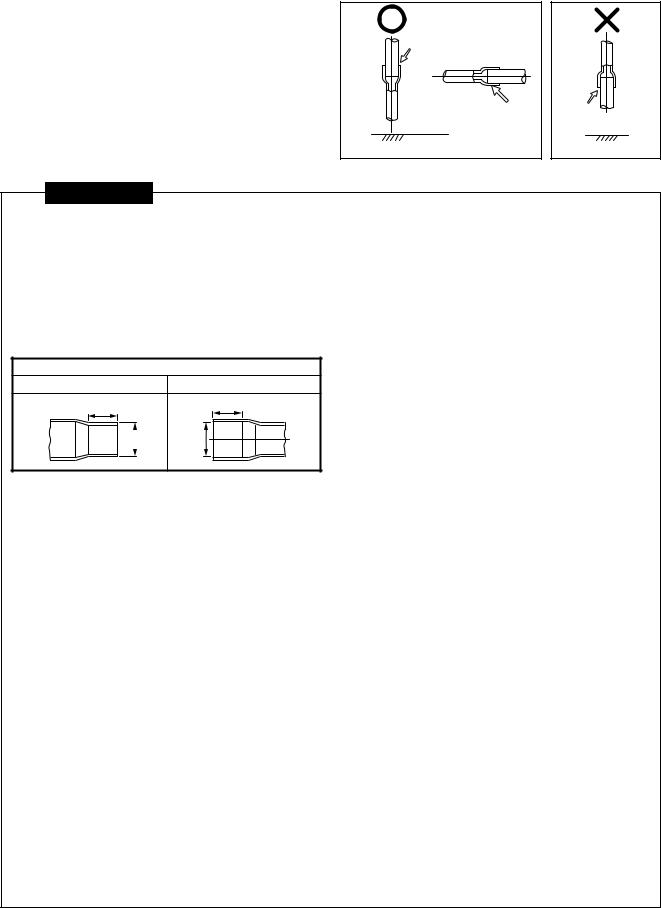
5-10. Brazing Work
1. |
Brazing work should be performed downwards or |
(Recommended brazing) |
|
|
sideways. Avoid brazing upwards (in order to |
|
|
|
avoid incomplete brazing). (Recommendation) |
|
|
2. |
Always used the specified piping materials for |
Brazing material |
|
|
liquid pipes and gas pipes, and make sure that |
|
|
|
|
|
|
|
they are installed in the proper direction and at |
|
|
|
the proper angle. |
|
|
3. |
The “nitrogen gas blow” method should be used |
Lateral direction |
|
|
when brazing. |
Brazing |
Brazing |
|
material |
||
|
|
material |
|
|
|
(Direction downward) |
(Direction upward) |
CAUTIONS
1.Pay attention to fire prevention concerns. (Take preventative measures in the area where brazing work is to be performed, such as keeping a fire extinguisher or water handy.)
2.Be careful not to burn yourself.
3.Make sure that any gaps between pipes and couplings are appropriate. (Do not miss brazing any joints.)
4.Make sure that pipes are adequately supported.
•The following table provides basic guidelines for the interval between supports for horizontal copper pipe.
Coupling size of brazed pipe
Connected section
External size |
Internal size |
K |
G |
ØC |
ØF |
Interval between supports for copper pipe
Nominal dia. |
20 or less |
25 to 40 |
|
|
|
Max. interval (m) |
1.0 |
1.5 |
|
|
|
•Avoid securing copper pipes with metal brackets directly.
|
|
|
|
|
|
|
|
(Unit: mm) |
|
|
|
Connected section |
|
|
|
||
Standard outer dia. of |
External size |
Internal size |
Min. depth |
|
Min. thickness |
|||
connected copper pipe |
Standard outer dia. (Allowable difference) |
of insertion |
Oval value |
of coupling |
||||
|
|
|
|
|
|
|
|
|
|
C |
|
F |
K |
|
G |
|
|
|
|
|
|
|
|
|
|
|
6.35 |
6.35 (±0.03) |
6.45 |
( +0.04–0.02 ) |
7 |
|
6 |
0.06 or less |
0.50 |
9.52 |
9.52 (±0.03) |
9.62 |
( +0.04–0.02 ) |
8 |
|
7 |
0.08 or less |
0.60 |
12.70 |
12.70 (±0.03) |
12.81 |
( +0.04–0.02 ) |
9 |
|
8 |
0.10 or less |
0.70 |
15.88 |
15.88 (±0.03) |
16.00 |
( +0.04–0.02 ) |
9 |
|
8 |
0.13 or less |
0.80 |
|
|
|
|
|
|
|
|
|
19.05 |
19.05 (±0.03) |
19.19 |
( +0.03–0.03 ) |
11 |
|
10 |
0.15 or less |
0.80 |
|
|
|
|
|
|
|
|
|
22.22 |
22.22 (±0.03) |
22.36 |
( +0.03–0.03 ) |
11 |
|
10 |
0.16 or less |
0.82 |
|
|
|
|
|
|
|
|
|
28.58 |
28.58 (±0.04) |
28.75 |
( +0.06–0.02 ) |
13 |
|
12 |
0.20 or less |
1.00 |
Gas brazing of refrigerant pipes must be performed by personnel qualified to do so under local ordinances.
Minmum wall thickness for R410A application
Soft (Coil) |
Hard or Half hard |
OD (Inch) |
OD (mm) |
Minium wall thickness |
|
|
|
|
|
¡ |
¡ |
1/4 |
6.35 |
0.80 |
|
|
|
|
|
¡ |
¡ |
3/8 |
9.52 |
0.80 |
|
|
|
|
|
¡ |
¡ |
1/2 |
12.70 |
0.80 |
|
|
|
|
|
¡ |
¡ |
5/8 |
15.88 |
1.00 |
|
|
|
|
|
NG |
¡ |
3/4 |
19.05 |
1.00 |
|
|
|
|
|
NG |
¡ |
7/8 |
22.20 |
1.00 |
|
|
|
|
|
NG |
¡ |
1.1/8 |
28.58 |
1.00 |
|
|
|
|
|
24
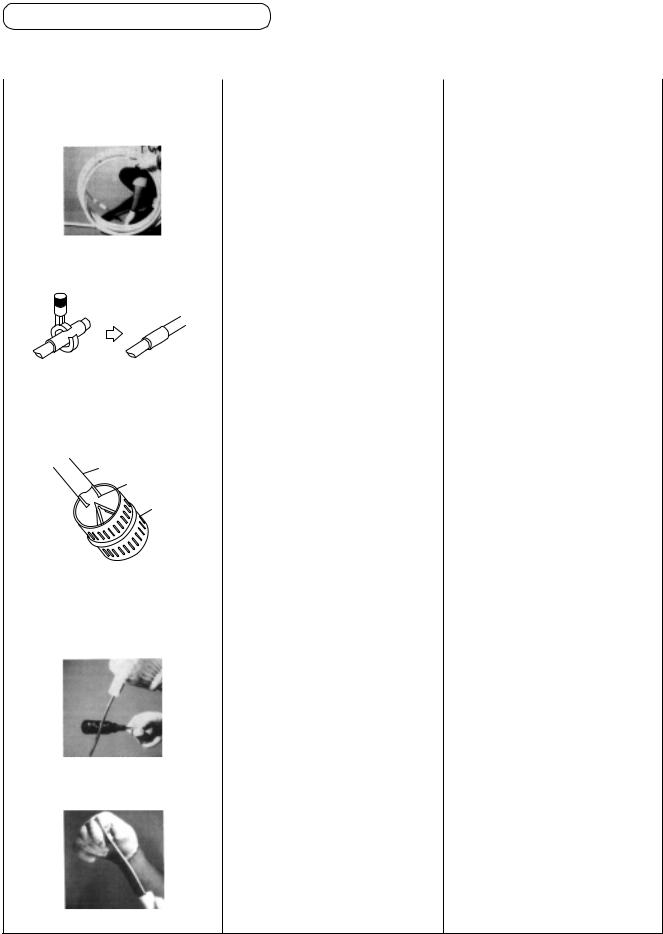
5-11. Flare Processing
Flare processing procedure
Parts and material |
: Copper pipe, flare nut. Flare nut shallbe of attached on the indoor unit or R410A exclusive. |
||
Tools |
: Flare tool (“Rigid” type), reamer, pipe cutter |
|
|
|
|
|
|
Work procedure |
Key point |
(Reason) |
|
|
|
|
|
Straighten the coiled copper pipe. |
Uncoil the pipe. |
• It is difficult to cut the coiled pipe |
|
|
|
|
correctly, which increases the |
|
|
|
chance of failure. |
Cut the pipe with the pipe cutter. |
1. |
Position the blade of the cutter |
• |
The cut surface will be at an |
|
|
so that it will cut the pipe at a |
|
angle. |
|
|
perpendicular angle. |
|
|
|
2. |
Rotate the pipe cutter to the |
• |
The cutter will bite too tightly. |
|
|
left to cut the pipe. |
|
|
|
3. |
Move the pipe cutter slowly. |
• |
The copper pipe will be |
|
|
|
|
deformed. |
Use the reamer to remove burrs |
1 . Keep the opening of the pipe |
• Scraps will get inside of the |
||
from the cut surface of the pipe. |
|
facing downwards. |
|
pipe. |
Pipe |
2. |
Be careful not to scratch the |
• |
A gas leak could result. |
|
inner surface of the pipe. |
|
|
|
Burr |
|
|
|
|
Deburring |
|
|
|
|
Clear out the inside of the pipe by |
Make sure that all scraps of metal |
• |
Metal scraps in the tube can |
tapping on the end with a |
are out of the tube by lightly |
|
damage the compressor. |
screwdriver. |
tapping on the tube while the |
• |
If the scraps adhere to the |
|
opening is pointing down. |
|
flared region, a gas leak may |
|
|
|
result. |
Insert the flare nut. |
Be certain to insert the flare nut |
|
before beginning the flare |
|
process. |
•The flare nut will not fit inside the copper pipe after the flare process.
25
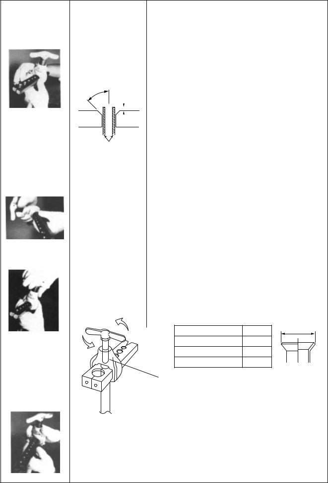
Work procedure |
Key point |
|
|
|
|
(Reason) |
|
|
||||||||
|
|
|
|
|
|
|
|
|
|
|
|
|
|
|
||
Attach the (“Rigid”) |
1. Make sure that the |
• |
The copper pipe will slip out while the flaring process is in |
|||||||||||||
flare tool to the |
inner surfaces of the |
|
progress. |
|
|
|
|
|
|
|
|
|
||||
copper pipe. |
flare tool are clean. |
• |
The flared dimensions vary. |
|
|
|
|
|
||||||||
|
2. Determine the |
|
Dimensions to end of copper tube when flared with one tool |
|||||||||||||
|
dimensions of the |
|
||||||||||||||
|
|
surface |
|
|
|
|
|
|
|
|
|
|||||
|
copper pipe in |
|
|
|
|
|
|
|
|
|
|
|||||
|
|
|
|
|
|
|
|
|
|
|
|
|||||
|
accordance with the |
• Projection margin in flaring : A (Unit : mm) |
||||||||||||||
|
flare tool. |
|||||||||||||||
|
|
Rigid (Clutch type) |
|
|
|
|
|
|
|
|||||||
|
|
|
|
|
|
|
|
|
|
|
|
|
|
|||
|
45˚ |
|
|
|
|
|
|
|
|
|
|
|
||||
|
|
Outer dia. of |
|
R410A tool used |
|
Conventional tool used |
|
|||||||||
|
|
|
|
|
|
|
|
|
|
|||||||
|
|
|
|
|
|
|
copper pipe |
|
R410A |
R22 |
|
R410A |
R22 |
|
||
|
|
|
|
|
|
|
|
|
|
|||||||
|
|
A |
|
|
|
|
|
|
|
|
|
|
|
|||
|
|
6.4 |
|
0 to 0.5 |
(Same as left) |
|
1.0 to 1.5 |
0.5 to 1.0 |
|
|||||||
|
Flare tool |
|
|
|
|
|
|
|
||||||||
|
|
|
|
|
|
|
|
|||||||||
|
|
|
|
|
|
|
|
|
|
|
|
|
|
|||
|
|
9.5 |
|
0 to 0.5 |
(Same as left) |
|
1.0 to 1.5 |
0.5 to 1.0 |
|
|||||||
|
|
|
|
|
|
|||||||||||
|
|
|
|
|
|
|
|
|
|
|||||||
|
|
|
|
|
|
|
|
|
|
|
|
|
|
|
|
|
|
|
|
|
|
|
|
12.7 |
|
0 to 0.5 |
(Same as left) |
|
1.0 to 1.5 |
0.5 to 1.0 |
|
||
|
Copper pipe |
|
15.9 |
|
0 to 0.5 |
(Same as left) |
|
1.0 to 1.5 |
0.5 to 1.0 |
|
||||||
|
|
|
|
|
|
|
|
|
|
|
|
|||||
Align the punch. |
|
Imperial (Wing nut type) |
|
|
|
|
|
|||||||||
Align the arrow on the |
|
|
|
|
|
|
||||||||||
|
|
|
|
|
|
|
|
|
|
|
||||||
|
Outer dia. of copper pipe |
|
R410A |
|
R22 |
|
||||||||||
(Align the arrow with |
punch with the |
|
|
|
|
|||||||||||
|
|
|
|
|
|
|
|
|
|
|
||||||
|
|
6.4 |
|
1.5 to 2.0 |
|
1.0 to 1.5 |
|
|||||||||
the line adjacent to |
prescribed position on |
|
|
|
|
|
||||||||||
|
|
9.5 |
|
1.5 to 2.0 |
|
1.0 to 1.5 |
|
|||||||||
the next hole.) |
the flare tool. |
|
|
|
|
|
||||||||||
|
|
|
|
|
|
|
|
12.7 |
|
2.0 to 2.5 |
|
1.5 to 2.0 |
|
|||
|
|
|
|
|
|
|
|
15.9 |
|
2.0 to 2.5 |
|
1.5 to 2.0 |
|
|||
|
|
|
|
|
|
|
|
|
|
|
|
|
|
|
|
|
•If the “A” dimension is small, the flared contact surface is smaller and a gas leak becomes more likely.
Flare the pipe. |
Slowly and carefully turn |
• The pipe will not be flared fully. |
|
|
|
the flare tool handle |
• The extended portion of the pipe (the cone-shaped portion) |
||
|
while it clicks, until it |
will be scratched. |
|
|
|
turns freely. Turn the |
|
|
|
|
handle to the left and |
|
|
|
|
raise it to the top. |
• Extruding margin of copper pipe |
|
|
|
|
|
||
|
|
with flare machining : A (Unit: mm) |
|
|
|
|
Copper pipe outer dia. |
+0.0 |
A |
|
|
A –0.4 |
||
|
|
9.5 |
13.2 |
|
|
|
12.7 |
16.6 |
|
|
|
15.9 |
19.7 |
|
Remove the flare tool |
If the handle is not raised to the |
|
top, the flare tool will scratch the |
||
and check the flared |
||
extended portion of the pipe |
||
surface. |
||
(the cone-shaped portion). |
||
|
Check list :
•Is the inner surface of the flared portion equal in width and shiny?
•Is the thickness of the flared portion equal?
•Is the flared portion of a suitable size?
26
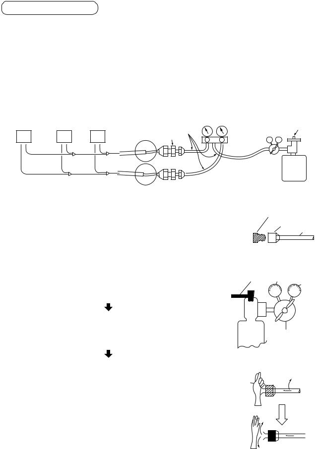
5-12. Flushing
The flushing process uses gas pressure to remove foreign matter from the inside of pipes.
Three major effects
(1)Removes oxidation that formed inside of the pipe during brazing as a result of an inadequate “nitrogen gas blow” procedure.
(2)Removes foreign matter and moisture that has gotten inside of pipes due to improper handling.
(3)Checks the connections in the pipe system between the indoor unit and the outdoor unit.
[Example work procedure]
1.Install a pressure reducing valve on a nitrogen cylinder. (Fluorocarbon gases and carbon dioxide carry a risk of promoting condensation, while oxygen causes explosion.)
2.Connect the pressure reducing valve to a gauge manifold and then to the gas-side pipe and the liquid-side pipe on the outdoor unit.
Indoor unit
|
|
|
Ø6.4 copper pipe |
|
Source valve |
|
|
|
|
Gauge |
|
N |
2 |
1 |
Diff. size union |
|
|
VL VH |
manifold |
||||
|
|
|
|
valve |
|
|
|
|
|
|
|
|
|
|
|
|
Reducing |
|
|
|
|
|
valve |
|
|
|
|
|
Nitrogen gas bomb |
3. On the indoor unit side, plug all gas-side pipes except those for the |
|
Plug (Brass) |
|||
indoor units that are to be flushed. |
|
|
Flare nut |
||
|
|
|
|
|
Copper pipe |
4.Open the source valve on the nitrogen cylinder and increase the pressure on the secondary side of the pressure reducing valve until it reaches 0.5MPa (5kg/cm2G), and then open the valve on the gauge manifold connected to the gas-side pipe.
5.Flushing
Press down on the end of the indoor-side gas pipe with your palm.
When the pressure becomes so great that you can no longer hold it against the end of the pipe, remove your hand from the pipe. (This is the first flush.) Press down against the end with your hand again.
Flush the pipe a second time.
(When flushing, place a piece of gauze, etc., on the end of the pipe, and then check the gauze for debris or moisture. Repeat the flushing process until nothing more comes out of the pipe.)
6.Close the gauge manifold valve, and repeat the above process for next indoor unit (No. 2 to No. N). Close the gauge manifold valve, open the valve on the gauge manifold that is connected to the liquidside pipe to allow the nitrogen to flow, and flush that liquid-side pipe.
Source |
1st side |
valve |
2nd side 0.5MPa (5kg/cm²G)
Nitrogen |
Reducing valve |
gas |
|
Pressure
0.5MPa (5kg/cm²G)
Hand
27
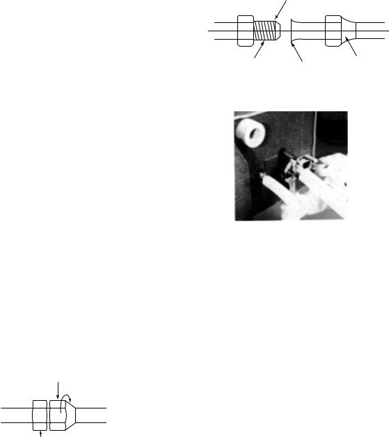
5-13. Pipe Connections to the Indoor Unit
1.Once you remove the flare nut from the pipe on the indoor unit (always use a torque wrench), a small amount of gas will escape, but this is simply nitrogen gas with atmospheric pressure that was sealed inside to prevent corrosion, and does not indicate a problem.
2.Flare the pipe according to the procedure described previously.
Tapered portion |
|
|
<Indoor unit> |
|
<Pipe> |
Center |
|
|
Brazing union |
Flared portion |
Flare nut |
(half union) |
|
|
|
|
|
3.Centering
Center the pipes be seating the tapered portion of the half union in the flared portion of the pipe.
4.Tightening the flare nut
First hand-tighten the flare nut as much as possible, and then use a torque wrench to tighten the nut completely.
Connecting pipe outer dia. |
Tightening torque |
|
(mm) |
(N•m) |
|
|
|
|
Ø6.4 |
14 to 18 (1.4 to 1.8 kgf•m) |
|
|
|
|
Ø9.5 |
34 to 42 (3.4 to 4.2 kgf•m) |
Tightening the flare nut with a torque wrench |
|
|
|
Ø12.7 |
50 to 62 (5.0 to 6.2 kgf•m) |
|
|
|
|
Ø15.9 |
68 to 82 (6.8 to 8.2 kgf•m) |
|
|
|
|
: R410A torque wrench required.
<Two spanners>
Turn flare nut with a wrench
<Indoor unit> |
<Pipe> |
Secure half union in place with a wrench
*Avoid initially tightening the nut with a wrench.
*When tightening a 6.4mm-diameter pipe, tighten the nut lightly with a wrench, and then tighten the nut about 90° to 120° (1.5 to 2 corners of the nut) with a torque wrench.
28

5-14. Pipe Connection to the Outdoor Unit
 WARNING
If the refrigerant gas leaks during installation work, ventilate the room.
If the leaked refrigerant gas comes to contact with a fire, the noxious gas may generate.
After installation work, check that the refrigerant gas does not leak.
If the refrigerant gas leaks in the room and comes to contact with a fire such as fan heater, stove, or kitchen range, the noxious gas may generate.
Connection of refrigerant pipe
1.The refrigerant pipe connecting section is set in the outdoor unit. Remove the front panel and the piping/wiring panel. (M5: 9 pcs.)
•As shown in the right figure, the hooking hooks are attached at right and left sides each on the front panel. Lift up and remove the front panel.
2.Pipes can be drawn out forward and downward from the outdoor unit.
3.When drawing out the pipe forward, draw out the pipe to outside via piping/wiring panel, and keep space of 500mm or more from the main pipe connecting the outdoor unit with the indoor unit, considering service work, etc. (For replacing the compressor, 500mm or more space is required.)
4.When drawing out the pipe downward, remove the knockout of the base plate of the outdoor unit, apply the pipe to outside of the outdoor unit, and perform piping at right/left or rear side. Leading pipe of the balancing should be within 4m.
500mm |
|
|
or |
more |
(Right |
(Left piping) |
|
piping) |
Drawing out forward
(Left piping) Drawing out downward
Hook |
|
|
Packed valve at |
|
suction gas side |
Front panel |
Packed valve |
Piping/wiring panel |
at liquid side |
|
Packed valve at balance side |
(Rear piping) |
(It is not used in this model.) |
|
|
(Right piping) |
Ball valve at discharge gas side |
|
REQUIREMENT
For brazing, be sure to use nitrogen gas to avoid oxidation of pipe inside.
1.In a welding work for the refrigerant pipes, be sure to use the nitrogen gas in order to prevent oxidation inside of the pipes; otherwise clogging of the refrigerating cycle due to oxidized scale generates.
2.Use clean and new pipes for the refrigerant pipes and perform piping work so that water or dust is not mixed.
3.Be sure to use a double spanner to loosen or tighten the flare nut. If a single spanner is
used, a required tightening cannot be obtained. Tighten the flare not with the specified torque.
Outer dia. of copper pipe |
Tightening torque (N•m) |
|
|
12.7 mm |
50 to 62 (5.0 to 6.2 kgf-m) |
|
|
15.9 mm |
68 to 82 (6.8 to 8.2 kgf-m) |
|
|
29

Pipe connecting method of valve (Example)
Using the attached pipes as shown in the following figure, braze elbows, sockets, and pipes which are procured locally.
MMY- |
Drawing out forward |
Drawing out downward |
|
|
|
|
|
|
Liquid pipe |
Use the attached pipe for connection. |
Pipe connection at the local site |
|
(Bend rightward slightly.) |
||
|
|
|
|
|
|
|
|
|
Discharge gas pipe |
Use the attached pipe (L-shape) and connect it |
Use the attached pipe (Straight pipe) and connect |
|
|
with socket. |
it with socket. |
|
Suction gas pipe |
Cut L-shape pipe and connect it with elbow, |
Cut L-shape pipe and connect it with attached pipe |
|
attached pipe and socket. |
and socket. |
|
|
|
||
|
Suction gas pipe |
Suction gas pipe |
Suction gas pipe |
Suction gas pipe |
|
|
|||
MAP0801FT8 |
Discharge |
Cut |
Discharge |
Cut |
gas pipe |
|
|
||
MAP1001FT8 |
|
gas pipe |
|
|
|
|
|
|
Liquid pipe |
|
Liquid pipe |
|
|
|
L-shape pipe |
|
|
|
|
|
L-shape pipe |
|
|
|
|
|
|
|
|
Attached pipe |
Attached |
|
|
|
Pipe |
pipe |
Attached pipe |
|
|
|
||
|
|
Attached pipe |
|
|
|
|
Socket |
Pipe |
Socket |
|
|
|
||
|
Attached pipe |
|
Socket |
|
|
|
|
Pipe |
|
|
|
Pipe |
Pipe |
|
|
Socket |
|
||
|
Pipe |
|
|
|
Liquid pipe |
Use the attached pipe for connection. |
Pipe connection at the local site |
||
(Bend rightward slightly.) |
|
|||
|
|
|
|
|
Discharge gas pipe Use the attached pipe and connect it with socket. |
Use the attached pipe (Straight pipe) and connect |
|||
it with socket. |
|
|||
|
|
|
|
|
Suction gas pipe |
Cut L-shape pipe and connect it with attached |
Cut L-shape pipe and connect it with attached pipe |
||
pipe. |
|
and socket. |
|
|
|
|
|
||
Suction gas pipe |
Suction gas pipe |
Suction gas pipe |
Suction gas pipe |
|
|||
Discharge |
Cut |
Discharge |
Cut |
gas pipe |
|
|
|
|
gas pipe |
|
|
MAP1201FT8 |
|
|
Liquid pipe |
|
Liquid pipe |
|
|
L-shape pipe |
|
|
|
|
L-shape pipe |
|
|
|
|
|
|
Attached pipe |
Attached |
|
|
|
pipe |
Attached pipe |
|
Pipe |
|
|
|
|
|
|
|
|
Pipe |
Socket |
|
|
|
|
Attached pipe |
|
Socket |
|
|
|
Pipe |
|
|
Pipe |
Pipe |
|
|
|
||
Socket |
Pipe |
|
|
|
|
30
 Loading...