


 Loading...
FILE NO : A06-009
Quick reference
R410A

01 Refrigerant Piping
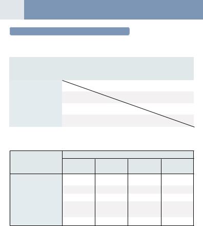
Allowable length of refrigerant pipe and height difference
Height difference between outdoor units H3 £ 5 m
Height difference between outdoor and indoor units H1 £ 50 m
|
|
|
|
|
|
|
|
|
|
|
Follower unit C |
• Cautions concerned with installation/construction |
|
|
|||||||||
|
|
|
|
|
|
|
|
|
|
|
|
|
|
|
|
1) The leading outdoor unit connected with the indoor |
|||||||
|
|
|
|
|
|
|
|
|
|
|
|
|
|
|
|
|
inter-unit pipe is made “A (Header unit)”. |
|
|
||||
|
|
|
|
|
|
|
|
|
|
|
|
|
|
|
|
2) |
Set the units in order of the outdoor capacity. |
|
|
||||
|
|
|
|
|
|
|
|
|
|
|
|
|
|
|
|
|
(A (Header unit) > B > C > D) |
|
|
|
|
||
|
|
|
|
|
|
|
|
|
|
|
|
|
|
|
|
3) |
For the combination of the outdoor units, refer to |
|
|
||||
|
|
Header unit A |
Follower unit B |
|
|
|
|
“Combination of outdoor unit” list. |
|
|
|
|
|||||||||||
|
|
Outdoor unit |
|
|
|
|
|
|
|
|
|
|
|
|
Note: |
|
|
|
|
||||
|
|
|
|
|
|
|
|
|
|
|
|
|
|
|
|
In case of connecting method <Ex.2>, a large amount of |
|||||||
|
|
|
|
|
|
|
|
|
|
|
|
|
|
|
|
refrigerant and refrigerant oil may return to the head unit. |
|||||||
T-Shape branching |
|
|
|
|
|
|
|
|
|
|
|
|
|
Therefore, set the T-shape joint so that oil does not enter directly. |
|||||||||
|
La |
LA |
|
Lb |
Lc |
|
|
|
|
|
|
|
|
|
|||||||||
main piping |
|
|
|
|
|
|
|
|
|
<Ex.1> Header |
Follower |
Follower |
|||||||||||
|
|
|
|
|
|
|
|
|
|
|
|
|
|
|
|
|
|||||||
|
|
|
|
|
Main connecting piping between outdoor units |
|
|
|
unit A |
unit B |
unit C |
||||||||||||
|
|
|
|
|
Length corresponded to farthest piping |
|
|
|
|
|
|
|
|
|
|||||||||
L1 |
|
between outdoor units LO £ 25 m |
|
|
|
|
|
|
|
|
|
||||||||||||
|
|
|
|
|
|
|
|
|
|
|
|
|
|
|
|
|
|
|
|
||||
|
|
|
|
|
|
|
|
|
|
|
|
|
|
|
|
|
|
|
|
|
|
|
|
|
Branching piping |
L2 |
Branching header |
|
|
|
|
||
|
Connecting piping of |
|
|
OK |
|
||||
1st |
|
|
|
|
|
||||
indoor unit |
|
|
L9 |
|
|
|
|
||
branching |
|
|
|
|
|
<Ex.2> |
Header |
Follower |
Follower |
section |
a |
b |
|
c |
|
|
unit A |
unit B |
unit C |
L3 |
|
|
|
||||||
|
|
|
FS unit |
|
|
|
|
|
|
|
g |
h |
i |
j |
k |
|
|
|
|
|
Indoor unit |
|
<Cooling only> |
<Cooling only> |
|
|
|
||
|
Equivalent length corresponded to farthest piping L £ 150 m |
|
|
|
|||||
|
Equivalent length corresponded to farthest piping after 1st branching Li £ 50 m |
|
|
|
|||||
|
|
|
|
|
|
|
|
|
|
|
|
|
|
|
|
|
|
|
|
|
Lj |
|
|
|
|
|
NO GOOD |
|||
|
|
|
|
L4 |
|
L5 |
|
|
L6 |
|
L7 |
|
L8 |
|
|
|
|
|
|
|
Height difference between |
|||||||||
|
|
|
|
|
|
|
|
|
|
|
|
|
|
|
|
|
|
|
|
|
|
|
|
|
|
|
|
indoor units H2 £ 35 |
||
|
|
|
|
d |
|
e |
|
|
|
|
f |
FS unit |
|
|
|
|
|
|
|
|
|
|
(Upper outdoor unit) |
|||||||
|
|
|
|
|
|
|
|
|
|
|
|
o |
|
|
|
|
|
|
|
|
|
|
||||||||
FS unit |
|
|
|
|
|
|
|
|
|
|
|
Lh |
|
|
|
|
|
|
|
|
|
|
|
|
|
|||||
|
|
|
l |
|
|
m |
|
|
|
|
n |
|
|
|
|
|
|
|
|
|
|
|
|
|
|
|
|
|
|
Height difference between |
|
|
|
|
|
|
|
|
|
|
|
|
|
|
|
|
|
|
|
|
|
|
|
|
|
|
|
|
|
|
|
|
|
|
Indoor unit |
|
|
|
|
|
|
|
|
|
|
|
|
|
|
|
|
|
|
|
|
|
||||||
|
|
|
|
|
|
|
|
|
|
|
|
|
|
|
|
|
|
p |
|
q |
|
|
|
|
|
indoor units in group control |
||||
|
|
|
|
|
|
|
|
|
|
|
|
|
|
|
|
|
|
|
|
|
|
|
|
|
|
|
|
|
|
by one FS unit H4 £ 0.5 m |
Indoor unit which FS unit control wiring is connected. |
|
|
|
|
<Group control> |
|
|
|
|
|||||||||||||||||||||
|
|
|
|
|
|
|
|
|||||||||||||||||||||||
|
|
|
|
|
|
|
|
|||||||||||||||||||||||
When connecting the plural indoor units to single FS unit.
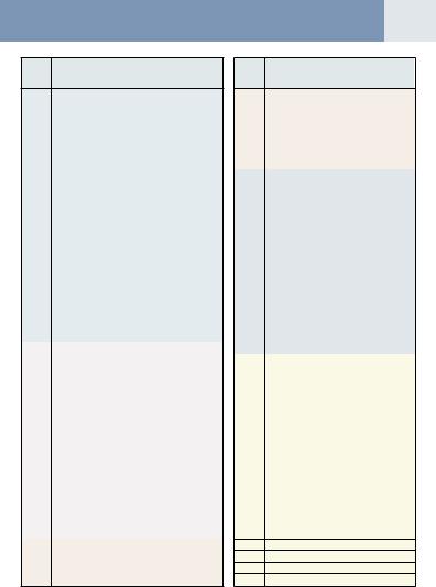
• Allowable length/height difference of the refrigerant pipe
|
|
|
Allowable value |
Pipe section |
|
|
Total extension of pipe (Liquid pipe/real length) |
300 m |
LA + La + Lb + Lc + L1 + L2 + L3 + L4 + L5 + L6 + L7 + L8 + L9 |
||
|
+ a + b + c + d + e + f + g + h + i + j + k + l + m + n + o+ p + q |
||||
|
|
|
|
||
|
Farthest piping length L (*1) |
Real length |
125 m |
LA + Lc + L1 + L3 + L4 + L5 + L6 + L7 + L8 + q |
|
|
Equivalent length |
150 m |
|||
|
Max. equivalent length of main piping |
|
85 m |
L1 |
|
Pipe |
Equivalent length of farthest piping from 1 st branching Li (*1) |
50 m |
L3 + L4 + L5 + L6 + L7 + L8 + q |
||
Max. real length of indoor unit connecting piping |
30 m |
a + g, b + h, c + i, d + l, e + m, f + m, f + n, j, k |
|||
length |
|||||
|
Max. real length between FS unit and indoor unit (*2) |
15 m |
g, h, i, l, m, n, L7 + o |
||
|
Max. equivalent length of outdoor unit connecting pipe LO (*1) |
25 m |
LA + Lc (LA + Lb) |
||
|
Max. real length of outdoor unit connecting pipe |
10 m |
La, Lb, Lc |
||
|
Max. equivalent length between FS unit and indoor unit Lj |
30 m |
L7 + L8 + p, L7 + L8 + q |
||
|
Max. real length between FS unit and indoor unit which FS unit |
15 m |
L7 + o |
||
|
control wiring is connected Lh (*2) |
|
|||
|
Upper outdoor unit |
50 m |
—— |
||
|
Height between |
||||
|
indoor unit and outdoor unit H1 |
Lower outdoor unit |
30 m |
—— |
|
Height |
Height between |
Upper outdoor unit |
35 m |
—— |
|
difference |
indoor unit H2 |
Lower outdoor unit |
15 m |
—— |
|
|
Height between outdoor units H3 |
|
5 m |
—— |
|
|
Height difference between indoor units in group control by one |
0.5 m |
—— |
||
|
FS unit H4 |
|
|||
|
|
|
|
||
*1 : The farthest indoor unit from 1st branch to be named C, and farthest indoor unit from 1st branch to be named (q). *2 : Attached connection cable can be used up to 5 m in pipe length between indoor unit and FS unit.
When the pipe length between indoor and FS unit exceeds 5 m, be sure to use the connection cable kit (RBC-CBK15FE).
• Restriction to the system
Max. No. of combined outdoor units |
3 units |
||
Max. capacity of combined outdoor units |
84.0 kW |
||
Max. No. of connected indoor units |
48 units |
||
Max. capacity of connected indoor units |
H2 < 15 m |
135% (*3) |
|
H2 > 15 m |
105% |
||
|
|||
Min. capacity of connected indoor units |
Outdoor capacity : 70% |
||
*3 : MMY-MAP1202FT8 up to 120%.
Note 1) Combination of outdoor unit : Header unit (1 unit) + Follow unit (0 to 2 units). Header unit is outdoor unit nearest to the connected indoor units.
Note 2) Install the outdoor units in order of capacity. (Header unit > Follow unit 1 > Follow unit 2)
Note 3) Refer to outdoor unit combination table in page 5.
Note 4) Piping to indoor units shall be perpendicular to piping to the head outdoor unit as <Ex. 1>. Do not connect piping to indoor units in the same direction of head outdoor unit as <Ex. 2>.

02
Addition of refrigerant
After vacuuming work, exchange the vacuum pump with the refrigerant bomb and then start the additional charging work of refrigerant.
Calculation of additional refrigerant charge amount
Refrigerant charge amount at shipment from the factory does not include the refrigerant for pipe at the local site. For refrigerant to be charged in pipe at the local site, calculate the amount and charge it additionally.
Note) If the additional refrigerant amount indicates minus as the result of calculation, use the air conditioner without addition of refrigerant.
|
|
Outdoor unit Model |
|
|
|
|
|
MMY-MAP0802FT8 |
MMY-MAP1002FT8 |
|
MMY-MAP1202FT8 |
|||||||
|
|
Charging amount (kg) |
|
|
|
|
|
|
|
|
|
|
|
11.5 |
|
|
|
|
|
|
|
|
|
|
|
|
|
|
|||||||||
|
|
Additional refrigerant |
= |
( |
Real length |
Additional refrigerant charge |
|
|
Compensation by |
|||||||||
|
|
charge amount at local site |
of liquid pipe × |
amount per 1m liquid pipe (Table 1) ) |
× 1.3 system HP (Table 2) |
|||||||||||||
Example : Additional charge amount R (kg) = {(L1 × 0.025kg/m) + (L2 × 0.055kg/m) + (L3 × 0.105kg/m)} × 1.3 |
||||||||||||||||||
|
|
|
|
|
|
|
|
|
L1 : Real total length of liquid pipe Ø6.4 (m) |
|
|
|||||||
|
|
|
|
|
|
|
|
|
L2 : Real total length of liquid pipe Ø9.5 (m) |
|
|
|||||||
|
|
|
|
|
|
|
|
|
L3 : Real total length of liquid pipe Ø12.7 (m) |
|
|
|||||||
|
|
|
|
|
|
|
|
|
System : 10HP |
|
|
|
|
|
|
|
||
Table-1 |
|
|
|
|
|
|
Table-2 |
|
|
|
|
|
|
|
|
|
||
|
|
|
|
|
|
|
|
|
|
|
|
|
|
|
||||
Liquid |
|
Additional refrigerant |
|
|
|
|
Combined |
|
Combined outdoor unit |
C (Corrected refrigerant amount) |
||||||||
|
|
|
|
|
(HP) |
|
|
|
|
(HP) |
|
|
|
(kg) |
||||
pipe dia. |
|
|
|
|
|
|
|
|
|
|
|
|
||||||
|
amount/1m liquid pipe (kg/m) |
|
|
|
|
|
|
|
|
|
|
|
|
|||||
(mm) |
|
|
|
|
|
|
8 |
|
|
8 |
|
|
|
|
2.0 |
|||
|
|
|
|
|
|
|
|
|
10 |
|
|
10 |
|
|
|
|
2.5 |
|
6.4 |
|
|
0.025 |
|
|
|
|
|
|
|
|
|
|
|
||||
|
|
|
|
|
|
|
12 |
|
|
12 |
|
|
|
|
3.0 |
|||
|
|
|
|
|
|
|
|
|
|
|
|
|
|
|||||
9.5 |
|
|
0.055 |
|
|
|
|
|
|
|
|
|
|
|
||||
|
|
|
|
|
|
|
16 |
|
|
8 |
|
8 |
|
|
|
–1.5 |
||
12.7 |
|
|
0.105 |
|
|
|
|
|
18 |
|
|
10 |
|
8 |
|
|
0.0 |
|
|
|
|
|
|
|
|
20 |
|
|
10 |
|
10 |
|
|
2.0 |
|||
|
|
|
|
|
|
|
|
|
|
|
|
|
||||||
15.9 |
|
|
0.160 |
|
|
|
|
|
|
|
|
|
|
|||||
|
|
|
|
|
|
|
24 |
|
|
8 |
|
8 |
8 |
|
|
–4.5 |
||
|
|
|
|
|
|
|
|
|
|
|
|
|
||||||
19.1 |
|
|
0.250 |
|
|
|
|
|
26 |
|
|
10 |
|
8 |
8 |
|
|
–3.0 |
|
|
|
|
|
|
|
|
|
28 |
|
|
10 |
|
10 |
8 |
|
|
–1.5 |
22.2 |
|
|
0.350 |
|
|
|
|
|
|
|
|
|
|
|||||
|
|
|
|
|
|
|
30 |
|
|
10 |
|
10 |
10 |
|
0.0 |
|||
|
|
|
|
|
|
|
|
|
|
|
|
|||||||
Charging of refrigerant
•Keeping valve of the outdoor unit closed, be sure to charge the liquid refrigerant into service port at liquid side.
•If the specified amount of refrigerant cannot be charged, open fully valves of outdoor unit at liquid and discharge/ suction gas sides, balance side operate the air conditioner in COOL mode under condition that valve at suction gas side is a little returned to close side, and then charge refrigerant into service port at suction gas side. In this time, choke the refrigerant slightly by operating valve of the bomb to charge liquid refrigerant.
The liquid refrigerant may be charged suddenly, therefore be sure to charge refrigerant gradually.
•When refrigerant leaks and refrigerant shortage occurs in the system, recover the refrigerant in the system and recharge refrigerant newly up to the correct level.
REQUIREMENT
<Entry of refrigerant charge amount>
•Fill the additional refrigerant record column of the wiring diagram indication plate with the additional refrigerant amount at installation work, total refrigerant amount and the name of the service man who charged refrigerant at installation time.
•The total refrigerant amount means the total value of the refrigerant amount at shipment and the additional refrigerant amount at installation time. The refrigerant amount at the shipment is one described on the “Unit nameplate”.

03 Refrigerant Piping Diagram (Outdoor)
Inverter unit (8, 10, 12HP)
Model: MMY-MAP0802FT8, MAP1002FT8, MAP1202FT8
|
|
Propeller fan |
|
|
|
FM Fan motor |
|
|
Sensor |
(Right side) |
|
|
(TE1) |
|
|
|
|
Sensor |
|
|
|
|
|
Strainer |
|
Main heat exchanger |
(TO) |
Pulse motor valve |
|
(Left side) |
|
Solenoid valve |
|
|
|
(SV12) |
|
Main heat exchanger |
|
|
|
|
(PMV1) (PMV2) |
Strainer |
Sub heat exchanger (Right side) |
|
|||
|
|
|||||
Check valve |
(PMV3) |
Sub heat exchanger (Left side) |
|
|||
|
Check valve |
Solenoid valve (SV11) |
4-Way valve |
|||
Strainer |
|
|
||||
|
|
|
|
|
Capillary |
|
|
Solenoid valve |
|
|
|
|
|
|
|
|
|
|
tube |
|
|
(SV5) |
|
|
|
|
|
|
|
|
|
|
|
|
|
Capillary |
High-pressure |
Check valve |
|
||
|
tube |
|
||||
|
|
sensor |
|
|
|
|
|
Solenoid valve |
Check joint |
|
Solenoid valve |
||
|
(SV6) |
Strainer |
|
(SV2) |
||
Sensor |
Capillary tube |
|
|
Capillary tube |
||
|
|
Oil |
|
|
||
(TL) |
Solenoid valve |
|
separator |
|
||
|
|
|
|
|
|
|
|
(SV3D) |
|
Strainer |
|
|
|
|
Capillary tube |
|
|
|
||
|
Solenoid valve |
Check valve |
|
Check valve Solenoid valve |
||
|
(SV41) |
|
|
|
|
(SV42) |
|
High-pressure |
|
|
Strainer |
High-pressure |
|
Liquid |
|
|
|
|||
tank |
switch |
Capillary |
|
Solenoid valve |
switch |
|
|
Sensor |
tube |
|
(SV3C) |
Sensor |
|
|
|
|
|
|
||
|
(TD1) |
|
Sensor |
|
|
(TD2) |
|
|
|
(TK3) |
|
|
|
Check |
Compressor 1 |
Strainer |
|
Strainer Compressor 2 |
||
(Inverter) |
|
|
(Inverter) |
|||
joint |
|
|
||||
|
|
Check |
|
Check |
|
|
|
|
|
valve |
|
valve |
|
|
|
Capillary tube |
|
Capillary tube |
|
|
|
|
|
Sensor |
|
Sensor |
|
|
|
|
(TK1) |
|
(TK2) |
|
|
Solenoid valve |
|
|
|
Oil tank |
|
|
Sensor (TK4) |
|
|
|
||
|
(SV3E) |
|
|
|
||
|
Capillary tube |
|
|
|
Capillary tube |
|
Strainer |
Strainer |
Solenoid valve |
|
Solenoid valve |
|
|
(SV3A) |
|
|
||||
|
Strainer |
Check valve |
|
(SV3B) |
|
|
|
|
|
|
|||
|
|
|
|
|
Check valve |
|
Sensor
(TS1) Low-pressure
sensor
Sensor
(TS2)
Check
joint
Accumulator
|
|
|
|
|
Service valve |
Service valve at |
|
||
of balance pipe |
discharge gas side |
|
||
|
Service |
valve |
Service |
valve at |
|
at liquid side |
suction gas side |
||

04
Explanation of functional parts
Functional part name |
|
|
|
Functional outline |
|
||
|
|
(Connector CN324: Red) |
|
|
|||
|
SV3A |
Closed : Allows oil to collect/remain in the oil tank. |
|
||||
|
|
Open |
: Allows oil to exit the oil tank. |
|
|||
|
SV3B |
(Connector CN313: Blue) |
|
|
|||
|
Open |
: Allows oil to return to the outdoor unit via the balance pipe. |
|
||||
|
|
|
|||||
|
SV3C |
(Connector CN314: Black) |
|
|
|||
|
Open |
: Pressurizes the oil tank. |
|
|
|||
|
|
|
|
||||
|
SV3D |
(Connector CN323: White) |
|
|
|||
|
Open |
: Supplies oil to the compressor from the oil separator. |
|
||||
|
|
|
|||||
|
SV3E |
(Connector CN323: White) |
|
|
|||
|
Open |
: Turns on during operation and balances oil between compressors. |
|||||
|
|
||||||
|
|
(Hot gas bypass) (Connector CN312: White) |
|
||||
|
ASV2 |
1) |
Low pressure release function |
|
|
||
|
2) |
High pressure release function |
|
|
|||
|
|
|
|
||||
Solenoid valve |
|
3) Gas balance function during stop time |
|
||||
|
|
(Gas balance control for compressor start-up) (Connector CN311: Blue) |
|||||
|
SV41 |
1) For gas balance start |
|
|
|||
|
SV42 |
2) High pressure release function |
|
|
|||
|
|
3) |
Low pressure release function |
|
|
||
|
|
(Connector CN310: White) |
|
|
|||
|
SV5 |
1) Increase of No. of heating indoor units, Gas balance function in defrost time |
|||||
|
|
2) |
Low-pressure balance function of discharge gas pipe during all cooling operation |
||||
|
SV6 |
(Connector CN309: White) |
|
|
|||
|
1) |
Liquid bypass function for discharge temp. release (Cooling bypass circuit) |
|||||
|
|
||||||
|
SV11 |
(Connector CN322: White) |
|
|
|||
|
1) |
For shutdown discharge gas (During all cooling operation and defrost operation) |
|||||
|
|
||||||
|
|
(Connector CN319: White) |
|
|
|||
|
SV12 |
1) Flow-rate control function of refrigerant to sub heat exchanger during simultaneous operation |
|||||
|
|
2) |
Flow-rate control function of refrigerant to sub heat exchanger during defrost operation |
||||
|
|
(Connector CN317: Blue) |
|
|
|||
4-way valve |
|
1) |
Cooling/Heating selection |
|
|
||
|
2) |
Reverse defrost |
|
|
|||
|
|
|
|
||||
|
|
3) |
Main-/Sub-heat exchanger selection |
|
|||
|
|
(Connector CN300, 301: White) |
|
|
|||
|
PMV1, 2 |
1) |
Super heat control function during all heating operation and mainly heating, partly cooling operation |
||||
|
2) |
Under-cool adjustment function during all cooling operation |
|
||||
|
|
|
|||||
Pulse motor valve |
|
3) |
Divided flow control function during mainly cooling, partly heating operation |
||||
|
(Connector CN302: Red) |
|
|
||||
|
|
|
|
||||
|
PMV3 |
1) |
For flow-rate control of sub heat exchanger during simultaneous operation |
||||
|
|
(Control function of heating divided flow) |
|
||||
|
|
|
|
||||
|
|
2) |
A function preventive high pressure up during all cooling or all heating operation |
||||
Oil separator |
|
1) |
Prevention for early drop of oil level (Decrease of flow-out of discharge oil to cycle) |
||||
|
2) |
Reserve function of surplus oil |
|
|
|||
|
|
|
|
||||
|
|
(TD1: Connector CN502: White, TD2: Connector CN503: Pink) |
|
||||
|
TD1, TD2 |
1) Protection of compressor discharge temp. |
|
||||
|
|
2) |
Releasing of discharge temp. |
|
|
||
|
TS1 |
(Connector CN504: White) |
|
|
|||
|
1) |
Controls super heat of PMV1 and 2 during all heating operation and simultaneous operation |
|||||
|
|
||||||
|
|
(Connector CN522: Black) |
|
|
|||
|
TS2 |
1) Controls indoor oil recovery during all cooling operation and mainly cooling, partly heating operation |
|||||
|
|
2) |
Detects overheat of cycle. |
|
|
||
Temp. sensor |
|
(Connector CN505: Green) |
|
|
|||
TE |
1) Controls defrost during all heating operation and simultaneous operation. |
||||||
|
|||||||
|
|
2) |
Controls outdoor fan during all heating operation and simultaneous operation. |
||||
|
TK1, TK2, |
æ |
TK1: Connector CN514: Black, |
TK2: Connector CN515: Green, |
ö |
||
|
è |
TK3: Connector CN516: Red, |
TK4: Connector CN523: Yellow |
ø |
|||
|
TK3, TK4 |
||||||
|
1) |
Judges oil level of compressor. |
|
|
|||
|
|
|
|
||||
|
TL |
(Connector CN521: White) |
|
|
|||
|
1) |
Detects under-cool during all cooling operation and simultaneous operation. |
|||||
|
|
||||||
|
TO |
(Connector CN507: Yellow) |
|
|
|||
|
1) |
Detects external ambient temperature. |
|
||||
|
|
|
|||||

05 Continued
Functional part name |
|
Functional outline |
|
|
|
(Connector CN501: Red) |
|
|
|
1) |
Detects high pressure and uses it to control capacity of compressor. |
|
|
2) |
Detects high pressure during all cooling operation and uses it to control fan when |
|
High pressure sensor |
|
cooling with low outside air. |
|
|
3) |
Detects under-cool of the indoor unit of which heating thermo.-ON during all heating |
Pressure sensor |
|
|
operation and simultaneous operation. |
|
4) |
Controls outdoor fan rpm during mainly cooling, part heating operation. |
|
|
|
|
|
|
|
(Connector CN500: White) |
|
|
|
1) |
Detects low pressure and uses it to control capacity of compressor during all cooling |
|
Low pressure sensor |
|
operation and simultaneous operation |
|
|
2) |
Detects low pressure and uses it to controls super heat during all heating operation |
|
|
|
and simultaneous operation |
|
Compressor case heater |
(Compressor 1 Connector CN316: White, Compressor 2 Connector CN315: Blue) |
|
|
1) |
Prevents liquid accumulation in the compressor |
|
Heater |
|
||
|
|
|
|
|
Accumulator case heater |
(Connector CN321: Red) |
|
|
1) |
Prevents liquid accumulation to accumulator |
|
|
|
||
|
|
|
|
Balance pipe |
1) Oil balancing pipe between outdoor unit (This unit does not use this Balance pipe.) |
||
|
|
|
|
<Operation mode>
|
|
Operation mode |
Outline |
|
|
|
|
|
|
1. |
All Indoor Unit(s) Operating for Cooling |
Only cooling operation without heating operation |
||
Outdoor heat exchanger (Main heat exchanger) is used as condenser. |
||||
|
|
|
||
|
|
|
|
|
2. |
All Indoor Unit(s) Operating for Heating |
Only heating operation without cooling operation |
||
Outdoor heat exchanger (Main heat exchanger) is used as evaporator. |
||||
|
|
|
||
|
|
|
|
|
3. |
Simultaneous operation |
MIU for simultaneous operation |
||
|
|
|
|
|
|
|
3-1. Mainly cooling, partly heating operation |
Cooling/heating simultaneous operation with subjective cooling operation |
|
|
|
Outdoor heat exchanger (Sub heat exchanger) is used as condenser. |
||
|
|
|
||
|
|
|
|
|
|
|
3-2. Mainly heating, partly cooling operation |
Cooling/heating simultaneous operation with subjective heating operation |
|
|
|
Outdoor heat exchanger (Main heat exchanger) is used as evaporator. |
||
|
|
|
||
|
|
|
|
|
4. |
Defrost |
Using reversing operation of 4-way valve, ice of the outdoor heat |
||
exchanger is dissolved with single cooling cycle. |
||||
|
|
|
||
|
|
|
|
|

|
|
06 |
Configuration of outdoor unit heat exchanger |
Flow Selector Unit (FS Unit) |
|
|
RBM-Y1122FE |
|
|
Liquid pipe Discharge gas pipe |
Suction gas pipe |
Propeller fan |
|
Strainer |
|
Strainer |
|
Capillary |
|
Capillary |
|
|
|
tube |
||
|
tube |
|
|
SVS |
Fan motor |
Check |
SVD |
|
Capillary |
|
tube |
|||
|
valve |
|
|
|
|
|
|
SVDD |
SVSS |
|
|
|
|
|
|
|
|
|
Strainer |
Main heat exchanger |
To indoor |
To indoor |
liquid side |
gas side |
|
|
RBM-Y1802FE |
Wind |
Wind |
* RBM-Y1801FE has two “SVS” valves. |
|
|
|
|
Liquid pipe |
Discharge gas pipe |
Suction gas pipe |
|
Sub heat |
Sub heat |
|
Strainer |
|
Strainer |
exchanger |
exchanger |
Capillary |
Capillary |
||
|
|
|
tube |
||
|
|
tube |
|
Capillary |
|
|
|
Check |
SVD |
||
|
|
|
tube |
||
|
|
valve |
|
|
SVS SVS |
|
|
|
|
|
|
|
|
|
SVDD |
|
SVSS |
|
|
|
|
|
Strainer |
Front side |
Rear side |
|
|
|
|
(Right) |
(Left) |
To indoor |
|
|
To indoor |
|
|
liquid side |
|
|
gas side |
RBM-Y2802FE
* RBM-Y2802FE has three “SVS” valves and two “SVD”.
Liquid pipe |
Discharge gas pipe |
Suction gas pipe |
|
Strainer |
Strainer |
Capillary |
Capillary |
|
tube |
||
tube |
|
Capillary |
Check |
|
|
|
tube |
|
valve |
SVD |
SVS SVS SVS |
|
||
|
SVDD |
SVSS |
|
|
Strainer |
To indoor |
To indoor |
liquid side |
gas side |
Functional part name |
|
Functional outline |
|
|
SVD |
(Discharge gas block valve) |
|
|
1) |
High pressure gas circuit during heating operation |
|
|
|
||
|
SVS |
(Suction gas block valve) |
|
|
1) |
Low pressure gas circuit during cooling operation |
|
|
|
||
Solenoid valve |
(Pressure valve) |
||
|
SVDD |
1) |
For pressurizing when No. of heating indoor units increases. |
(Reducing valve)
SVSS 1) For recovery of refrigerant of the stopped indoor unit of which cooling thermo-OFF 2) For reducing pressure when No. of heating indoor units decreases.
07 System Refrigerant Cycle Drawing
Refrigerant piping systematic diagram in system
<Selection of operation mode>
For the selection of each operation mode, see the table below:
“Stop Once” means the system does not operate for 3 minutes after operation before update has stopped.
|
|
|
After update |
|
|
|
|
|
|
|
|
|
|
All cooling operation |
Mainly cooling, partly |
Mainly heating, partly |
All heating operation |
|
|
|
heating cooperation |
cooling operation |
|
|
|
(OFF) |
(ON) |
(ON) |
(ON) |
|
|
|
|
|
|
|
All cooling operation |
|
Operation continues |
Operation continues |
Stop once |
|
(OFF) |
|
(OFF → ON) |
(OFF → ON) |
(OFF → ON) |
|
|
|
|
|
|
|
Mainly cooling, partly |
Operation continues |
|
Operation continues |
Operation continues |
Before |
heating cooperation (ON) |
(ON → OFF) |
|
(As ON) |
(As ON) |
|
|
|
|
|
|
update |
Mainly heating, partly |
Stop Once |
Operation continues |
|
Operation continues |
|
|
||||
|
cooling operation (ON) |
(ON → OFF) |
(As ON) |
|
(As ON) |
|
|
|
|
|
|
|
All heating operation |
Stop Once |
Operation continues |
Operation continues |
|
|
(ON) |
(ON → OFF) |
(As ON) |
(As ON) |
|
|
|
|
|
|
|
Note) Phrases in parentheses in the table indicate status of 4-way valve.
<ON-OFF list of Flow Selector Unit (FS Unit) valve>
Outline of control valve output of FS unit (Basic operation)
Indoor operation mode |
SVD |
SVDD |
|
(High pressure |
(Pressure valve |
|
circuit valve) |
<For delay>) |
SVS |
SVSS |
(Low pressure |
(Reducing valve |
circuit valve) |
<For delay>) |
1. |
Stop (Remote controller OFF) |
OFF |
OFF |
OFF |
ON |
|
|
<All system stop> |
<OFF> |
<OFF> |
<OFF> |
<OFF> |
|
|
|
|
|
|
|
|
2. |
Cooling thermo-OFF |
OFF |
OFF |
OFF |
ON |
|
|
|
|
|
|
|
|
3. |
Cooling thermo-ON |
OFF |
OFF |
ON |
ON |
|
|
|
|
|
|
|
|
4. |
Heating thermo-OFF |
|
|
|
|
|
|
|
ON |
OFF |
OFF |
OFF |
|
5. |
Heating thermo-ON |
|||||
|
|
|
|
|||
|
|
|
|
|
|
|
6. |
“E04” error is being detected |
OFF |
ON |
OFF |
OFF |
Check Code List |
08 |
Main
remote Check code name controller
display
E01 |
Communication error between indoor and remote controller |
|
(Detected at remote controller side) |
||
|
||
E02 |
Sending error of remote controller |
|
|
|
|
E03 |
Communication error between indoor and remote controller |
|
(Detected at indoor side) |
||
|
||
|
|
|
E04 |
Communication circuit error between indoor and outdoor |
|
(Detected at indoor side) |
||
|
||
|
|
|
E06 |
Decrease of No. of indoor units |
|
|
|
|
E07 |
Communication circuit error of indoor and outdoor |
|
(Detected at outdoor side) |
||
|
||
|
|
|
E08 |
Duplicated indoor addresses |
|
|
|
|
E09 |
Duplicated master remote controllers |
|
|
|
|
E10 |
Communication error in indoor P.C. B ass’y |
|
|
|
|
E12 |
Automatic address start error |
|
|
|
|
E15 |
No indoor automatic address |
|
|
|
|
E16 |
No. of connected indoor units / Capacity over |
|
|
|
|
E18 |
Communication error between indoor header and follower units |
|
|
|
|
E19 |
Outdoor header units quantity error |
|
|
|
|
E20 |
Other line connected during automatic address |
|
|
|
|
E23 |
Sending error in communication between outdoor units |
|
|
|
|
E25 |
Duplicated follower outdoor addresses |
|
|
|
|
E26 |
Decrease of No. of connected outdoor units |
|
|
|
|
E28 |
Follower outdoor error |
|
|
|
|
E31 |
IPDU communication error |
|
|
|
|
F01 |
Indoor TCJ sensor error |
|
|
|
|
F02 |
Indoor TC2 sensor error |
|
|
|
|
F03 |
Indoor TC1 sensor error |
|
|
|
|
F04 |
TD1 sensor error |
|
|
|
|
F05 |
TD2 sensor error |
|
|
|
|
F06 |
TE1 sensor error |
|
|
|
|
F07 |
TL sensor error |
|
|
|
|
F08 |
TO sensor error |
|
|
|
|
F10 |
Indoor TA sensor error |
|
|
|
|
F12 |
TS1, TS2 sensor error |
|
|
|
|
F13 |
TH sensor error |
|
|
|
|
F15 |
Outdoor temp sensor misconnecting (TE, TL) |
|
|
|
|
F16 |
Outdoor pressure sensor misconnecting (Pd, Ps) |
|
|
|
|
F23 |
Ps sensor error |
|
|
|
|
F24 |
Pd sensor error |
|
|
|
|
F29 |
Indoor other error |
|
|
|
|
F31 |
Outdoor EEPROM error |
|
|
|
|
H01 |
Compressor break down |
|
|
|
|
|
Magnet switch error |
|
H02 |
Overcurrent relay operation |
|
|
Compressor error (lock) |
|
|
|
|
H03 |
Current detect circuit system error |
Main
remote Check code name controller
display
H04 |
Comp 1 case thermo operation |
|
H06 |
Low pressure protective operation |
|
|
|
|
H07 |
Oil level down detective protection |
|
|
|
|
H08 |
Oil level detective temp sensor error |
|
|
|
|
H14 |
Comp 2 case thermo operation |
|
|
|
|
|
Oil level detective circuit error |
|
H16 |
Magnet switch error |
|
|
Overcurrent relay operation |
|
L03 |
Duplicated indoor header units |
|
|
|
|
L04 |
Duplicated outdoor line addresses |
|
|
|
|
L05 |
Duplicated indoor units with priority |
|
(Displayed on indoor unit with priority) |
||
|
||
|
|
|
L06 |
Duplicated indoor units with priority |
|
(Displayed in unit other than indoor unit with priority) |
||
|
||
|
|
|
L07 |
Group line in individual indoor unit |
|
|
|
|
L08 |
Indoor group/Address unset |
|
|
|
|
L09 |
Indoor capacity unset |
|
|
|
|
L10 |
Outdoor capacity unset |
|
|
|
|
L17 |
Inconsistency error of outdoor units |
|
|
|
|
L18 |
FS unit error |
|
|
|
|
L20 |
Duplicated central control addresses |
|
|
|
|
L28 |
Over No. of connected outdoor units |
|
|
|
|
L29 |
No. of IPDU error |
|
|
|
|
L30 |
Auxiliary interlock in indoor unit |
|
|
|
|
L31 |
IC error |
|
|
|
|
P01 |
Indoor fan motor error |
|
|
|
|
P03 |
Discharge temp TD1 error |
|
|
|
|
P04 |
High-pressure SW detection error |
|
|
|
|
P05 |
Phase-missing detection / Phase order error |
|
|
|
|
P07 |
Heat sink overheat error |
|
|
|
|
P10 |
Indoor overflow error |
|
|
|
|
P12 |
Indoor fan motor error |
|
|
|
|
P13 |
Outdoor liquid back detection error |
|
|
|
|
P15 |
Gas leak detection |
|
|
|
|
P17 |
Discharge temp TD2 error |
|
|
|
|
P19 |
4-way valve inverse error |
|
|
|
|
P20 |
High-pressure protective operation |
|
|
|
|
P22 |
Outdoor fan IPDU error |
|
|
|
|
P26 |
G-TR short protection error |
|
|
|
|
P29 |
Comp position detective circuit system error |
|
|
|
|
P31 |
Other indoor unit error (Group follower unit error) |
—Error in indoor group
—AI-NET communication system error
—Duplicated network adaptors
09 Address Setup
Pre-check for address setup
<Check on outdoor unit>
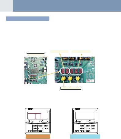
1.Check that all the rotary switches, SW01, SW02, and SW03 on the interface P.C. board of the outdoor unit are set up to “1”.
2. If other error code is displayed on 7-segment [B], remove the cause of trouble referring to “9. Troubleshooting”.
3.Check that [L08] is displayed on 7-segment display [B] on the interface P.C. board of the outdoor unit. (L08: Indoor address unset up)
(If the address setup operation has already finished in service time, etc, the above check code is not displayed, and only [U1] is displayed on 7-segment display [A].)
7-segment display [A] |
|
7-segment display [B] |
Interface P.C. board
SW01 SW02 SW03
<Check on indoor unit>
1.Display check on remote controller (In case of wired remote controller)
Check that a frame as shown in the following left figure is displayed on LC display section of the remote controller.
GOOD |
|
|
NO |
|
|
|
|
GOOD |
|
|
|
|
|
|
|
|
|
TEMP. |
|
ON / OFF |
TEMP. |
|
ON / OFF |
TIMER SET |
FAN |
MODE |
TIMER SET |
FAN |
MODE |
TIME |
SWING/FIX |
VENT |
TIME |
SWING/FIX |
VENT |
FILTER |
|
|
FILTER |
|
|
RESET TEST SET CL |
UNIT |
|
RESET TEST SET CL |
UNIT |
|
Normal status |
Abnormal status |
||||
(Power and operation stop) |
(Power is not normally turned on.) |
||||
If a frame is not displayed as shown in the above right figure, the power of the remote controller is not normally turned on. Therefore check the following items.
•Check power supply of indoor unit.
•Check wiring between indoor unit and remote controller.
•Check whether there is cutoff of cable around the indoor control P.C. board or not, and check connection failure of connectors.
•Check failure of transformer for the indoor microcomputer.
10
Automatic Address Setup
Without central control : To the address setup procedure 1 With central control : To the address setup procedure 2
(However, go to the procedure 1 when the central control is performed in a single refrigerant line.)
(Example) |
In case of central control in a single refrigerant line |
In case of central control over refrigerant lines |
Address setup procedure |
To procedure 1 |
To procedure 2 |
|
|
|
Cable systematic diagram |
|
|
Outdoor |
Central |
Outdoor |
Central |
Outdoor |
|
Outdoor |
Central |
|
remote controller |
|
remote controller |
|
|
|
remote controller |
Indoor |
Indoor |
Indoor |
Indoor |
Indoor |
Indoor |
Indoor |
Indoor |
Remote |
Remote |
Remote |
Remote |
Remote |
Remote |
Remote |
Remote |
controller |
controller |
controller |
controller |
controller |
controller |
controller |
controller |
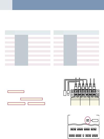
Address setup procedure 1
1.Turn on power of indoor/outdoor units.
(In order of indoor → Outdoor)
2. After approx. 1 minute, check that U. 1. L08 (U. 1. flash) is displayed in 7-segment display section on the interface P.C. board of the outdoor unit.
3.Push SW15 to start the setup of the automatic addressing. (Max. 10 minutes for 1 line (Usually, approx. 5 minutes))
4. When the count Auto 1 → Auto 2 → Auto 3 is displayed in 7-segment display section, and it changes from U. 1. - - - (U. 1. flash) to
U.1. - - - (U. 1. light) , the setup finished.
5.When performing an automatic address setup on a single refrigerant line with central control, connect relay connected between [U1, U2] and [U3, U4] terminals in the header unit.
REQUIREMENT
•When a group control is performed over the multiple refrigerant lines, be sure to turn on the power supplies of all the indoor units connected in a group at the time of address setup.
Header unit interface P.C. board
3
SW04 SW05 SW15


 2, 4
2, 4
D600 D601 D602 D603 D604
SW01 SW02 SW03
1 |
1 |
1 |
5
|
U3 U4 |
U5 U6 |
|
For internal |
For wiring of |
For internal |
|
wiring between |
central control |
wiring between |
|
indoor and |
system |
outdoor units |
|
outdoor |
|||
|
|
•If turning on the power for each refrigerant line to set up address, a header indoor unit is set for each line. Therefore, an alarm code “L03” (Duplicated header indoor units) is output in operation after address setup. In this case, change the group address from the wired remote controller for only one header unit is set up.
Header unit interface P.C. board
|
ON |
3 |
4 |
ON |
3 |
4 |
|
ON |
3 |
4 |
ON |
3 |
4 |
|
|||||
|
1 |
2 |
1 |
2 |
|
1 |
2 |
1 |
2 |
|
|||||||||
|
|
|
|
|
|
|
|
|
|
|
|
|
|
|
|
||||
|
|
SW11 |
|
|
SW12 |
|
|
|
SW13 |
|
|
SW14 |
|
|
|||||
ON |
3 |
4 |
ON |
3 |
4 |
|
ON |
|
ON |
3 |
4 |
ON |
3 |
4 |
|||||
1 |
2 |
1 |
2 |
|
1 |
|
1 |
2 |
1 |
2 |
|||||||||
|
|
|
|
|
|
|
|
|
|
|
|
|
|
|
|
||||
|
SW06 |
|
|
SW07 |
|
|
SW08 |
|
|
SW09 |
|
|
SW10 |
|
|||||
(Example) |
Group control over |
|
multiple refrigerant lines |
||
|
Cabling systematic |
|
|
|
|
diagram |
Outdoor |
|
Outdoor |
|
|
Indoor |
Indoor |
Indoor |
Indoor |
Remote |
Remote |
Remote |
Remote |
controller |
controller |
controller |
controller |
11 Continued
Address setup procedure 2
1.Using SW13 and 14 on the interface P.C. board of the outdoor unit in each system, set up the address for each system. (At shipment from factory: Set to Address 1)
Note) Be careful not to duplicate addresses with the other refrigerant line.
Line address switch on outdoor interface P.C. board
(¡: Switch ON, × : Switch OFF)
Line |
|
SW13 |
|
|
SW14 |
|
||
address |
1 |
2 |
3 |
4 |
1 |
2 |
3 |
4 |
1 |
|
|
|
× |
× |
× |
× |
× |
2 |
|
|
|
× |
¡ |
× |
× |
× |
3 |
|
|
|
× |
× |
¡ |
× |
× |
4 |
|
|
|
× |
¡ |
¡ |
× |
× |
5 |
|
|
|
× |
× |
× |
¡ |
× |
6 |
|
|
|
× |
¡ |
× |
¡ |
× |
7 |
|
|
|
× |
× |
¡ |
¡ |
× |
8 |
|
|
|
× |
¡ |
¡ |
¡ |
× |
9 |
|
|
|
× |
× |
× |
× |
¡ |
10 |
|
|
|
× |
¡ |
× |
× |
¡ |
11 |
|
|
|
× |
× |
¡ |
× |
¡ |
12 |
|
|
|
× |
¡ |
¡ |
× |
¡ |
13 |
|
|
|
× |
× |
× |
¡ |
¡ |
14 |
|
|
|
× |
¡ |
× |
¡ |
¡ |
Line |
|
SW13 |
|
|
SW14 |
|
||
address |
1 |
2 |
3 |
4 |
1 |
2 |
3 |
4 |
15 |
|
|
|
× |
× |
¡ |
¡ |
¡ |
16 |
|
|
|
× |
¡ |
¡ |
¡ |
¡ |
17 |
|
|
|
¡ |
× |
× |
× |
× |
18 |
|
|
|
¡ |
¡ |
× |
× |
× |
19 |
|
|
|
¡ |
× |
¡ |
× |
× |
20 |
|
|
|
¡ |
¡ |
¡ |
× |
× |
21 |
|
|
|
¡ |
× |
× |
¡ |
× |
22 |
|
|
|
¡ |
¡ |
× |
¡ |
× |
23 |
|
|
|
¡ |
× |
¡ |
¡ |
× |
24 |
|
|
|
¡ |
¡ |
¡ |
¡ |
× |
25 |
|
|
|
¡ |
× |
× |
× |
¡ |
26 |
|
|
|
¡ |
¡ |
× |
× |
¡ |
27 |
|
|
|
¡ |
× |
¡ |
× |
¡ |
28 |
|
|
|
¡ |
¡ |
¡ |
× |
¡ |
 : Is not used for setup of system address. (Do not change setup.)
2.Check that the relay connectors between [U1, U2] and [U3, U4] terminals are not connected in all the outdoor units to which the
central control is connected.
(At shipment from factory: Connector not connected)
3.Turn on power of indoor/outdoor. (In order of indoor → outdoor)
4.After approx. 1 minute, check that 7-segment display is
|
U.1.L08 (U.1. flash) |
on the interface P.C. board of the outdoor unit. |
|
|
|
|
5. |
Push SW15 to start the setup of automatic addressing. |
|
|
|
|
|
|
(Max. 10 minutes for 1 line (Usually, approx. 5 minutes)) |
2 |
|
|
|
|
6. |
When the count Auto 1 → Auto 2 → Auto 3 is displayed in |
U1 U2 |
U3 U4 |
U5 U6 |
||
|
7-segment display section, and it changes from |
|
For internal |
For wiring of |
For internal |
|
|
U. 1. - - - (U. 1. flash) |
to U. 1. - - - (U. 1. light) , the setup finished. |
|
wiring between |
central control wiring between |
|
|
|
indoor and |
system |
outdoor units |
||
|
|
|
|
outdoor |
|
|
7.Procedure 4. to 6. are repeated in other refrigerant lines.
8.How to set up the terminal resistance
When all the address setups have finished in the same refrigerant circuit system, put the terminal resistance in the same central
control line into one. |
Header unit interface P.C. board |
||
|
|
|
|
|
|
|
|
• Remain only SW30-2 of the header outdoor unit with address 1 as |
|
ON |
|
|
1 2 |
|
|
ON. (With end terminal resistance) |
|
|
SW30 |
• Set up SW30-2 of the other header outdoor units to OFF. |
|
SW30 |
|
(Without terminal resistance) |
|
|
|
9.Connect the relay connector between [U1, U2] and [U3, U4] of the header unit for each refrigerant line.
10.Then set up the central control address.
(For the central control address setup, refer to the Installation manual of the central control devices.)
|
ON |
3 |
4 |
ON |
3 |
4 |
|
ON |
3 |
4 |
ON |
3 |
4 |
|
|||||
|
1 |
2 |
1 |
2 |
|
1 |
2 |
1 |
2 |
|
|||||||||
|
|
|
|
|
|
|
|
|
|
|
|
|
|
|
|
||||
|
|
SW11 |
|
|
SW12 |
|
|
|
SW13 |
|
|
SW14 |
|
|
|||||
ON |
3 |
4 |
ON |
3 |
4 |
|
ON |
|
ON |
3 |
4 |
ON |
3 |
4 |
|||||
1 |
2 |
1 |
2 |
|
1 |
|
1 |
2 |
1 |
2 |
|||||||||
|
|
|
|
|
|
|
|
|
|
|
|
|
|
|
|
||||
|
SW06 |
|
|
SW07 |
|
|
SW08 |
|
|
SW09 |
|
|
SW10 |
|
|||||
Loading...