


MCY-MAP0601HT
Table of contents
 Loading...
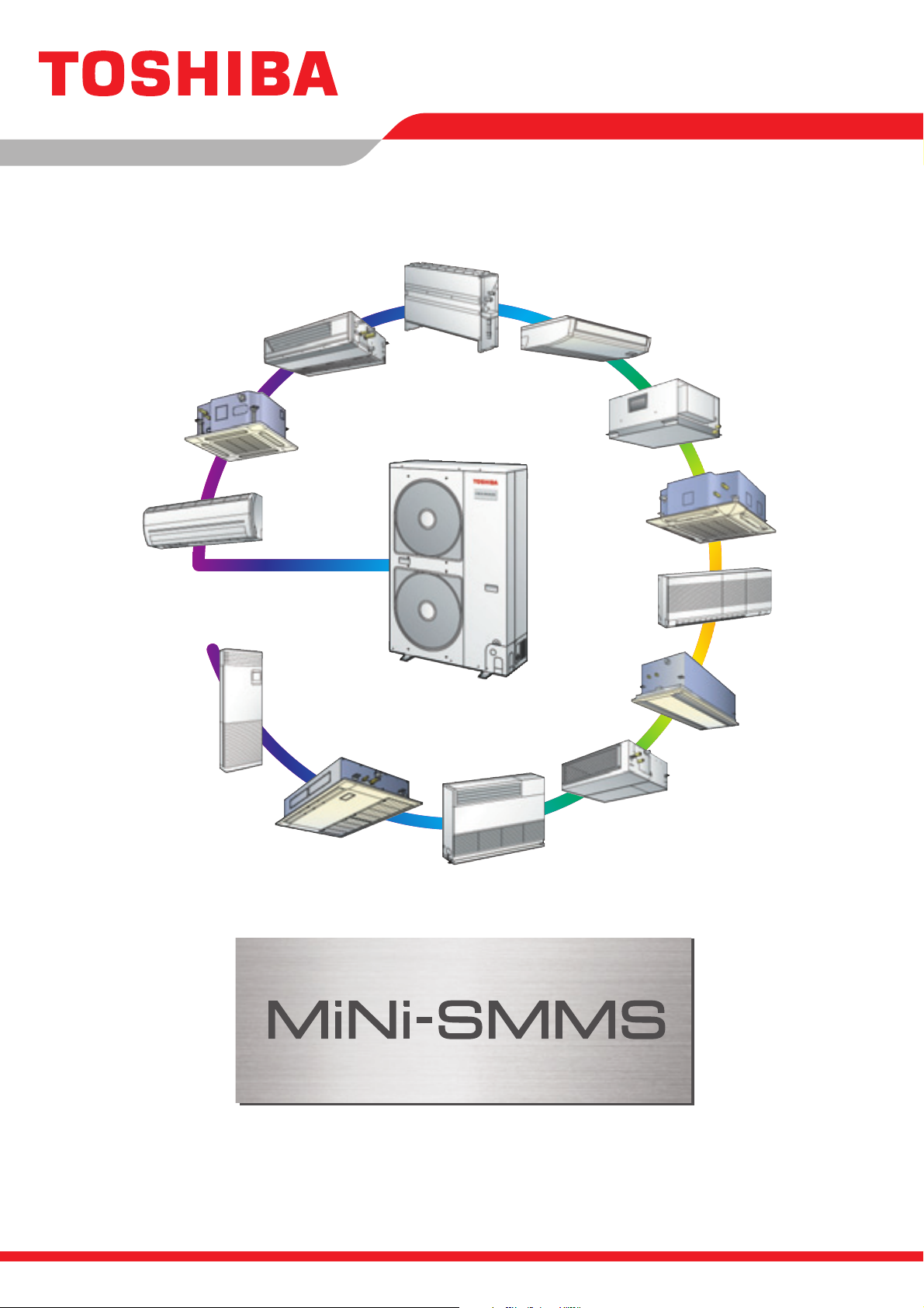
Engineering Data Book
File No. E06-311


1
-1
The engineering data book details all relevant data, charts and drawings to
enable you to get the best performance from the Toshiba Mini-SMMS for various
applications.
The information is aimed to assist you by providing greater system details and
the wider applications that system covers.
It is recommended that the data book be used in accordance with the following
as references.
Design manual: File No.A06-111
Installation manual: File No.A06-211
Service manual: File No.A05-016
2
-1
Contents
1. Forward ...................................................................................................................... 1-1
2. Contents .................................................................................................................... 2-1
3. Introduction ............................................................................................................... 3-1
4. System overview ....................................................................................................... 4-1
4-1. Summary of system equipments ....................................................................... 4-1
4-2. Outdoor units .................................................................................................... 4-2
4-3. Indoor units ....................................................................................................... 4-3
4-4. Branching joints and headers ........................................................................... 4-5
4-5. PMV Kit............................................................................................................. 4-5
4-6. Remote controller ............................................................................................. 4-6
5. Capacity compensation chart .................................................................................. 5-1
6. Piping requirements ................................................................................................. 6-1
7. Refrigerant cycle diagram ........................................................................................ 7-1
8. Wiring guideline ........................................................................................................ 8-1
9. Indoor unit line up ..................................................................................................... 9-1
9-1. 4-way Air Discharge Cassette Type ............................................................... 9-1-1
9-2. Compact 4-way Cassette (600 × 600) Type ................................................... 9-2-1
9-3. 2-way Air Discharge Cassette Type ............................................................... 9-3-1
9-4. 1-way Air Discharge Cassette Type (Included NewType) .............................. 9-4-1
9-5. Concealed Duct Standard Type ..................................................................... 9-5-1
9-6. Slim Duct Type ............................................................................................... 9-6-1
9-7. Concealed Duct High Static Pressure Type ................................................... 9-7-1
9-8. Under Ceiling Type ........................................................................................ 9-8-1
9-9. High Wall (1 series) Type ............................................................................... 9-9-1
9-10. High Wall (2 series) Type ............................................................................. 9-10-1
9-11. Floor Standing Cabinet Type ....................................................................... 9-11-1
9-12. Floor Standing Concealed Type .................................................................. 9-12-1
9-13. Floor Standing Type ..................................................................................... 9-13-1
9-14. Optional parts of indoor units ....................................................................... 9-14-1
10. PMV Kit .................................................................................................................... 10-1
11. Outdoor unit ............................................................................................................ 11-1
12. Controls ................................................................................................................... 12-1

World’s best class energy savings
• World-class energy savings — COP of 4.61* achieved by Toshiba’s
unrivalled SMMS technologies and newly developed components
*4HP CDU system
Flexible and easy installation
• Greater application versatility—13 types of indoor units for use in up to 9
rooms; max. 6 HP
• Small and light weight outdoor unit
• Total piping length 180 m* (forthest 100 m)
• Maximum height variation for indoor units
(Outdoor unit is up to 30 m higher than indoor unit / outdoor unit is up to 20 m lower than indoor unit)
*150 m with PMV kit
Pursue unexpected quieter operation
• Quiet operation enables a tranquil interior environment, which can be
further enhanced with our optional PMV* kit
• Product made from quieter outdoor unit by adoption of Bat wing fan
*Pulse Motor Valve
Toshiba MiNi-SMMS Air Conditioning
Greater Flexibility for Even More Comfort
• Superior new Toshiba VRF system for small and mid-sized buildings
• Toshiba’s innovative spirit — concept of VRF, all advantages of SMMS
Mini-SMMS Data book
Introduction
3
3
-1
1
2
3
4
5
6
7
8
9
10
11
12
World’s best class energy savings
World-class energy savings — COP of 4.61* achieved by Toshiba’s unrivalled
SMMS technologies and newly developed components
*4HP CDU system
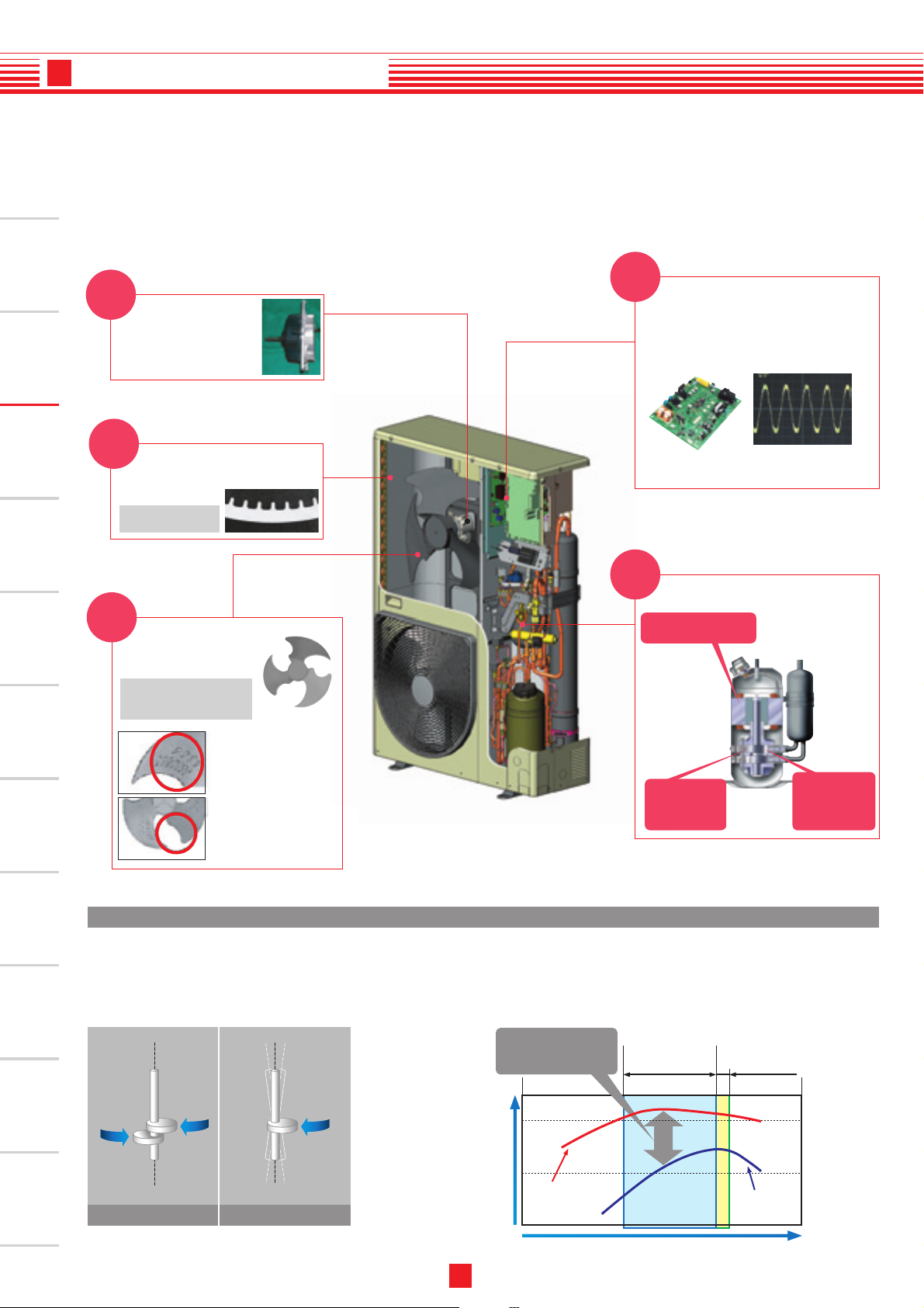
Vector-controlled inverter
Twin-rotary DC compressor
Vector IPDU control changes motor current
wave to a smooth sinusoidal pattern so that
noise emitted from the drive units is greatly
reduced.
Bat wing fan
DC fan motor
• High output / high
efficiency DC motor
• 600W output
• Sine wave drive
Heat exchanger
High-efficiency R410A
heat-transfer tube
Configuration of the finned
heat-transfer tube
Smooth sign curve liquid
realizes efficient-izing and
low noise-ization.
Efficient circuit built-in
and new PIM adoption
New development for high
pressure low sound fan
→
The bat wing fan realizes
the sound level equivalent
to current model.
New
New
New
New
New
Greater motor efficiency
from improved coil design
More effective
compression from
high-precision
components
Higher refrigerant
compression from
redesigned
compression
channels
High reliability
The enhanced DC twin-rotary compressor delivers stable performance with minimum friction:
Ideal for noise-sensitive applications. The outdoor unit is almost imperceptible.
• Low vibrations
• Super-quiet
operation
• High reliability
TWIN-ROTARY COMPRESSOR
DC twin rotary compressor (A3 comp) features
Partial load range
*Most frequent operation
Nominal range
Total efficiency of
compressor
DC Twin
rotary type
Conventional
Scroll type
Frequency of compressor (rps)
(%)
Comparison of DC twin rotary and Scroll compressor
Anti-eddy projection
Anti-eddy projection prevents
big eddies and reduces air
resistance.
Reverse-arc-shape wing
Reverse-arc-shape wing
reduces air resistance.
Toshiba Twin-Rotary
Traditional Compressor
This difference is the
reason for actual energy
savings
3
Introduction
1
2
3
4
5
6
7
8
9
10
11
12
3
-2
3
Introduction
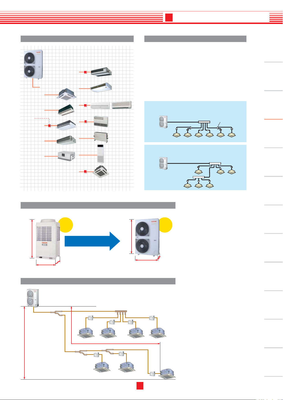
New compact 4-way
cassette
PMV-Kit
Line branching after header branching
Outdoor unit
Indoor unit
Br
anching joint
Header
PMV kit
Header branching after header branching
Outdoor unit
Indoor unit
Header
Header
PMV kit
Combination of line and header branching is highly
flexible, allowing the shortest route possible thereby
saving on installation time and costs. Line/header
branching after header branching is only available
with TOSHIBA.
Expansive variety in our line-up of indoor units Shortest route design by free branching
Small and lightweight
Piping length
900 mm
117kg228kg
1,340 mm
320 mm
1,800 mm
750 mm
990 mm
1-phase3-phase
Mini-SMMS outdoor unitSuper-MMS outdoor unit
Mini-SMMS is born from
our supreme VRF technology
Compact
- Line branching
- Header branching
- Line + Header branching
Best-in-class piping length and height
1
2
3
4
5
6
7
8
9
10
11
12
(Revised edition in 7.Apr.2006)
3
-3
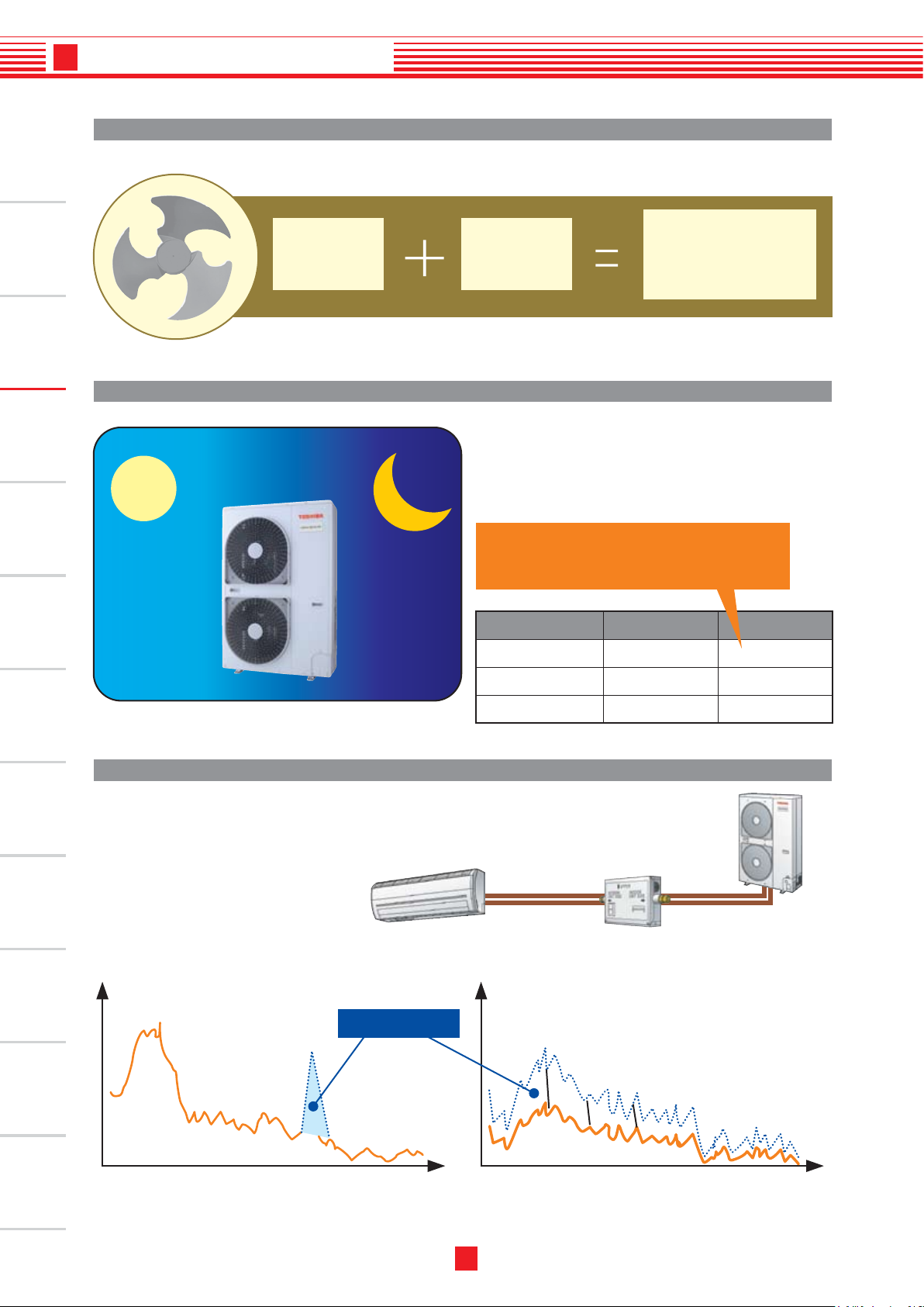
New bat
wing fan
DC fan
motor
Quiet er sound
and
power saving
Day
Day
Night
Night
Mi ni-SMMS ha s ti med , Night O peration , allowing
queter operation at night.
(A timer or a switch is local arrangements)
P M V k it (R B M- PM V0 3 61 E/ RB M -
PMV0 901E) sh all be re quired f or
q ui t e r p la c e a pp l ic a t io n a s an
optional to reduce refrigerant sound
especially in oil retrieval control or
in transient operation as start up.
4HP
5HP
6HP
49dB
50dB
51dB
46dB
46 dB
47dB
Daytime Night
Clears nighttime residential noise ordinances.
Can be used without obstructing peaceful
neighborhoods at night.
Bat Wing fan
Night operation mode
PMV kit
Quieter with smoother wind flow
Die-away Zone
Suppress particular-Hz noise away Suppress overall noise levels
(Hz) (Hz)
3
Introduction
1
2
3
4
5
6
7
8
9
10
11
12
3
-4
Outdoor unit
(Revised edition in 7.Apr.2006)

4
-1
4-1. Summary of system equipments
Sales launch scheduled for early 2006. Specifications differ by region.
For questions regarding availability, please contact your local distributor.
World-class energy savings
_
COP of 4.61* achieved by Toshiba’s unrivalled
S-MMS technologies and newly developed components
Quiet operation can be further enhanced with an optional PMV
(flow regulating valve) Kit.
Versatile application
_
13 types of indoor units for use in up to 9 rooms (6 HP)
*
4HP CDU system
*
Pulse Motor Valve
Use of quieter place
Necessity of PMV Kit (RBM-PMV0361E / RBM-PMV0901E) for
quieter place application as an optional.
New compact 4-way
cassette
PMV Kit
4
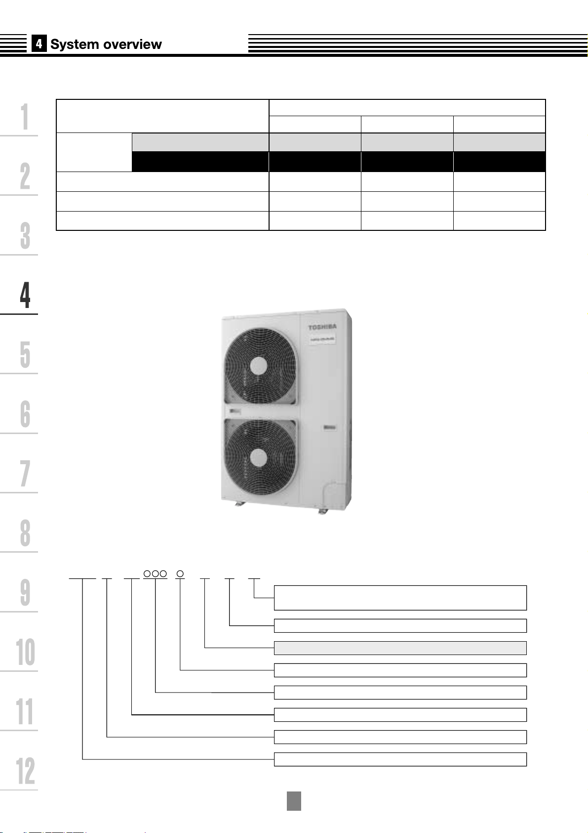
-2
4-2. Outdoor units
MCY- 2DMAP H T
Corresponding HP
Model
name
Heat pump(50Hz) MCY-
Heat pump(60Hz) MCY-
Cooling capacity(kW)*1
Heating capacity(kW)*1
No.of connectable indoor units
Inverter unit
4HP 5HP 6HP
MAP0401HT MAP0501HT MAP0601HT
MAP0401HT2D MAP0501HT2D MAP0601HT2D
12.1
12.5
6
14.0
16.0
8
15.5
18.0
9
*1 Rated conditions
Cooling:Indoor air temperature 27
o
C DB/19
o
CWB,Outdoor air temperature 35
o
CDB
Heating:Indoor air temperature 20
o
C DB,Outdoor air temperature 7
o
CDB/6
o
CWB
Allocation standard of model name
No mark: Power supply specification, 1O
/
220-240V, 50Hz
2D : Power supply specification, 1
O
/
220V, 60Hz
T : Inverter unit
H : Heat pump
Development Number
Capacity rank HP
x
10
R410A
M : Individual unit
Multi Compact Type
4
-3
Type
Appearance
Model name
Capacity rank
Capacity
code
Cooling
capacity (kW)
Heating
capacity (kW)
4-way Air Discharge
Cassette Type
2-way Air Discharge
Cassette Type
1-way Air Discharge
Cassette Type
Slim Duct Type
Concealed Duct
Standard Type
Concealed Duct
High Static
Pressure Type
Under Ceilling Type
PMV Kit
Compact 4-way
Air Discharge
(600x600) Type
MMU-AP0091H
MMU-AP0121H
MMU-AP0151H
MMU-AP0181H
MMU-AP0241H
MMU-AP0271H
MMU-AP0301H
MMU-AP0361H
MMU-AP0481H
MMU-AP0071MH
MMU-AP0091MH
MMU-AP0121MH
MMU-AP0151MH
MMU-AP0181MH
MMU-AP0071WH
MMU-AP0091WH
MMU-AP0121WH
MMU-AP0151WH
MMU-AP0181WH
MMU-AP0241WH
MMU-AP0271WH
MMU-AP0301WH
MMU-AP0071YH
MMU-AP0091YH
MMU-AP0121YH
MMU-AP0152SH
MMU-AP0182SH
MMU-AP0242SH
MMD-AP0071BH
MMD-AP0091BH
MMD-AP0121BH
MMD-AP0151BH
MMD-AP0181BH
MMD-AP0241BH
MMD-AP0271BH
MMD-AP0301BH
MMD-AP0361BH
MMD-AP0481BH
MMD-AP0071SPH
MMD-AP0091SPH
MMD-AP0121SPH
MMD-AP0151SPH
MMD-AP0181SPH
MMD-AP0181H
MMD-AP0241H
MMD-AP0271H
MMD-AP0361H
MMD-AP0481H
MMC-AP0151H
MMC-AP0181H
MMC-AP0241H
MMC-AP0271H
MMC-AP0361H
MMC-AP0481H
009 type
012 type
015 type
018 type
024 type
027 type
030 type
036 type
048 type
007 type
009 type
012 type
015 type
018 type
007 type
009 type
012 type
015 type
018 type
024 type
027 type
030 type
007 type
009 type
012 type
015 type
018 type
024 type
007 type
009 type
012 type
015 type
018 type
024 type
027 type
030 type
036 type
048 type
007 type
009 type
012 type
015 type
018 type
018 type
024 type
027 type
036 type
048 type
015 type
018 type
024 type
027 type
036 type
048 type
1.00
1.25
1.70
2.00
2.50
3.00
3.20
4.00
5.00
0.80
1.00
1.25
1.70
2.00
0.80
1.00
1.25
1.70
2.00
2.50
3.00
3.20
0.80
1.00
1.25
1.70
2.00
2.50
0.80
1.00
1.25
1.70
2.00
2.50
3.00
3.20
4.00
5.00
0.80
1.00
1.25
1.70
2.00
2.00
2.50
3.00
4.00
5.00
1.70
2.00
2.50
3.00
4.00
5.00
2.8
3.6
4.5
5.6
7.1
8.0
9.0
11.2
14.0
2.2
2.8
3.6
4.5
5.6
2.2
2.8
3.6
4.5
5.6
7.1
8.0
9.0
2.2
2.8
3.6
4.5
5.6
7.1
2.2
2.8
3.6
4.5
5.6
7.1
8.0
9.0
11.2
14.0
2.2
2.8
3.6
4.5
5.6
5.6
7.1
8.0
11.2
14.0
4.5
5.6
7.1
8.0
11.2
14.0
3.2
4.0
5.0
6.3
8.0
9.0
10.0
12.5
16.0
2.5
3.2
4.0
5.0
6.3
2.5
3.2
4.0
5.0
6.3
8.0
9.0
10.0
2.5
3.2
4.0
5.0
6.3
8.0
2.5
3.2
4.0
5.0
6.3
8.0
9.0
10.0
12.5
16.0
2.5
3.2
4.0
5.0
6.3
6.3
8.0
9.0
10.0
16.0
5.0
6.3
8.0
9.0
12.5
16.0
Available
Available
Available
Available
Available
Available
Available
Available
Available
Available
Available
Available
Available
Available
Available
Available
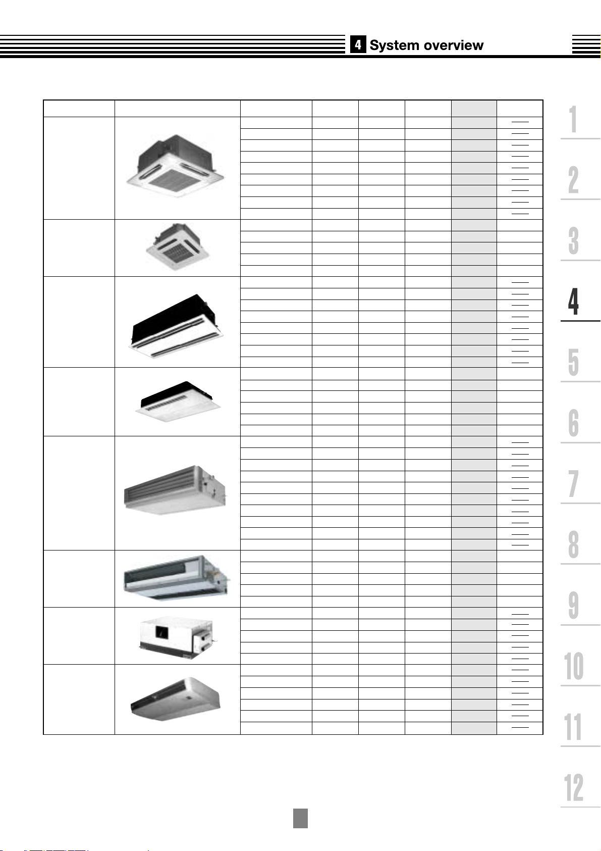
4-3. Indoor units
4
-4
--AP H
MM
Allocation standard of model name
M : Compact 4-way Cassete Type
W : 2-way Cassete Type
S : 1-way Cassete Type
Y : Small sized 1-way Cassete Type
B : Built-in Type (Built-in Duct Type)
(Floor concealed Type)
SP(S) : Slim Duct Type
C : China model
U : Cassette Type
D : Duct Type
C : Under Ceiling Type
K : High Wall Type
L : Floor Type (Cabinet type)
(Concealed type)
F : Floor Standing Type
Development series No.
Based on the cooling capacity (Btu/h)/1,000
R410A
MM : Modular Multi Type
PMV Kit
007 type
009 type
012 type
015 type
018 type
024 type
007 type
009 type
012 type
007 type
009 type
012 type
015 type
018 type
024 type
007 type
009 type
012 type
015 type
018 type
024 type
015 type
018 type
024 type
027 type
036 type
048 type
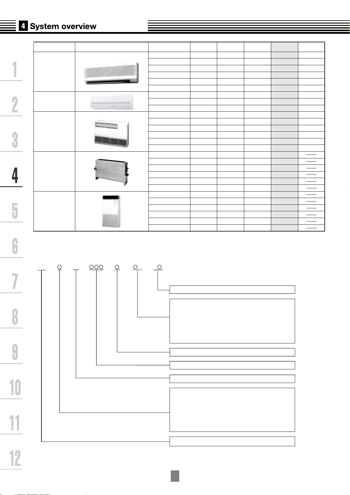
Type Appearance Model name
Capacity
rank
Capacity
code
Cooling
capacity (kW)
Heating
capacity (kW)
Floor Standing
Cabinet Type
Floor Standing
Concealed Type
Floor Standing Type
MMK-AP0071H
MMK-AP0091H
MMK-AP0121H
MMK-AP0151H
MMK-AP0181H
MMK-AP0241H
MMK-AP0072H
MMK-AP0092H
MMK-AP0122H
MML-AP0071H
MML-AP0091H
MML-AP0121H
MML-AP0151H
MML-AP0181H
MML-AP0241H
MML-AP0071BH
MML-AP0091BH
MML-AP0121BH
MML-AP0151BH
MML-AP0181BH
MML-AP0241BH
MMF-AP0151H
MMF-AP0181H
MMF-AP0241H
MMF-AP0271H
MMF-AP0361H
MMF-AP0481H
0.80
1.00
1.25
1.70
2.00
2.50
0.80
1.00
1.25
0.80
1.00
1.25
1.70
2.00
2.50
0.80
1.00
1.25
1.70
2.00
2.50
1.70
2.00
2.50
3.00
4.00
5.00
2.2
2.8
3.6
4.5
5.6
7.1
2.2
2.8
3.6
2.2
2.8
3.6
4.5
5.6
7.1
2.2
2.8
3.6
4.5
5.6
7.1
4.5
5.6
7.1
8.0
11.2
14.0
2.5
3.2
4.0
5.0
6.3
8.0
2.5
3.2
4.0
2.5
3.2
4.0
5.0
6.3
8.0
2.5
3.2
4.0
5.0
6.3
8.0
5.0
6.3
8.0
9.0
10.0
16.0
High Wall Type
(2 series)
High Wall Type
(1 series)
Available
Available
Available
Available
Available
Available
Available
Available
Available
Available
Available
Available
Available
Available
Available
4
-5
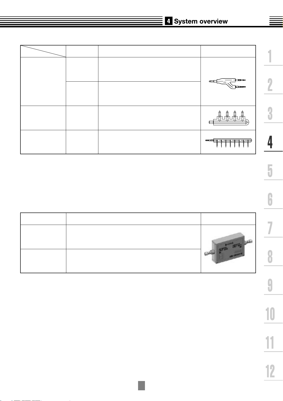
4-4. Branching joints and headers *1
*1 If total capacity code value of indoor unit exceeds that of outdoor unit, apply code of outdoor unit.
*2 "capacity code" can be obtained from page~. (capacity code is not actual capacity)
*3 When using Y-shape branching joint for 1st branching, select according to the capacity code of outdoor unit.
Model name
Usage Appearance
Y-shape branching joint
4-branching header
8-branching header
RBM-BY53E
RBM-BY103E
RBM-HY1043E
RBM-HY1083E
Indoor unit capacity code (*2) :Total below 6.4
Indoor unit capacity code (*2) :Total 6.4 or more
and below 7.8
Indoor unit capacity code (*2) :Total below 7.8
Indoor unit capacity code (*2) :Total below 7.8
4-5. PMV Kit
Indoor unit capacity type Appearance
RBM-PMV0361E
RBM-PMV0901E
007, 009, 012 type
015, 018, 024 type
For more information see Chapter 10.
Model name
4
-6
4-6. Remote controller
Name
Model
name
Appearance Application Function
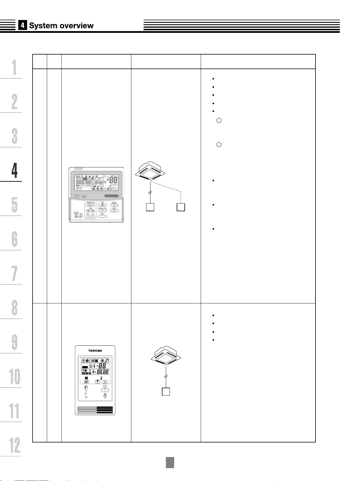
Wired remote controllerSimple wired remote controller
RBC-AS21E2
RBC-AMT31E
Connected to indoor unit
Connected to indoor unit
Simple remote controller
Wired remote
controller
Wired remote
controller
(In case of control
by 2 remote
controllers)
Start / Stop
Mode Change
Temperature setting
Fan speed
Timer function
Filter dirty indicator
Displays automatically maintenance
time of indoor filter by flashes.
Self-diagnosis function
Pressing "CHECK" button
displays status code.
Control by 2 remote controllers is
available.
Two remote controllers can be
connected to one indoor unit.
The indoor unit can be separately
operated from a different location.
1
2
Start / Stop
Temperature setting
Change of air flow
Check code display
On or off elapsed timer
with 30 minite increments.
Automatic off function
Weekly when combined with
RBC-EXW21E2
weekly schedule operation can
be operated.
ûC
ûF
TEST
SETTING
4
-7
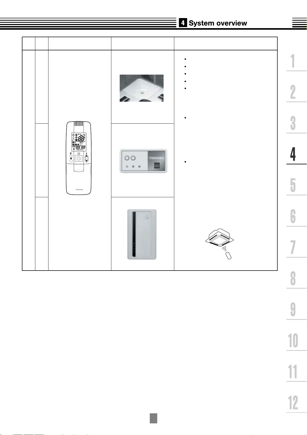
Wireless remote controller kit
TCB-AX21E2 RBC-AX22CE2 TCB-AX21U(W)-E2
Name
Model
name
Appearance Function
Start / Stop
Mode change
Temperature setting
Change of air flow
Timer function
On or off timer operation, setting in
30 minute increments.
Automatic Off function
Control by 2 remote controllers is
available.
Two wireless remote controllers can
operate one indoor unit. The indoor unit
can be separately operated from a
different location.
Check code display
TCB-AX21U(W)-E2
(for 4-way airdischarge cassette)
RBC-AX22CE2
(for under ceiling)
TCB-AX21-E2
(for other units except for the con-
cealed duct high static pressure)
4
-8
Name
Model
name
Appearance Application Performance
Central remote controller
TCB-SC642TLE2
Connected to outdoor unit,
or indoor unit
Outdoor
unit
Central
remote controller
Indoor
remote controller
Central
remote
controller
Individual control up to 64 indoor units.
Individual control for max. 64 indoor
units divided into 4 zones.
Up to 16 indoor units for each
zone
Up to 16 outdoor units are
connectable.
Four selectable central control settings to
restrict individual remote controller
operations.
Setting for one of 1 to 4 zones is
available.
Can be used with other central control
devices (Up to 10 central control
devices with in one control circuit)
Two selectable control modes
Central controller mode
Remote controller mode
Setting of simultaneous ON/OFF 3
times for each day of the week
combined with a weekly timer.
ON-OFF controller
TCB-CC163TLE2
Connected to outdoor unit,
or indoor unit
Indoor unit
Indoor
remote controller
Outdoor unit
ON-OFF
controller
ON-OFF
controller
Setting of simultaneous ON-OFF 3
times for each day of the week when
combined with a weekly timer.
Individual control up to 16 indoor units.
Connected to 2 remote controllers is
possible.
SELECT ZONE
CL
SET
GROUP
CODE
No.
UNIT No.
No.
R.C.
TEST
ZONE
ALL
ZONE
GROUP
SETTING
1234
SET DATA
4
-9
Name
Weekly timer
Model
name
Appearance Application Performance
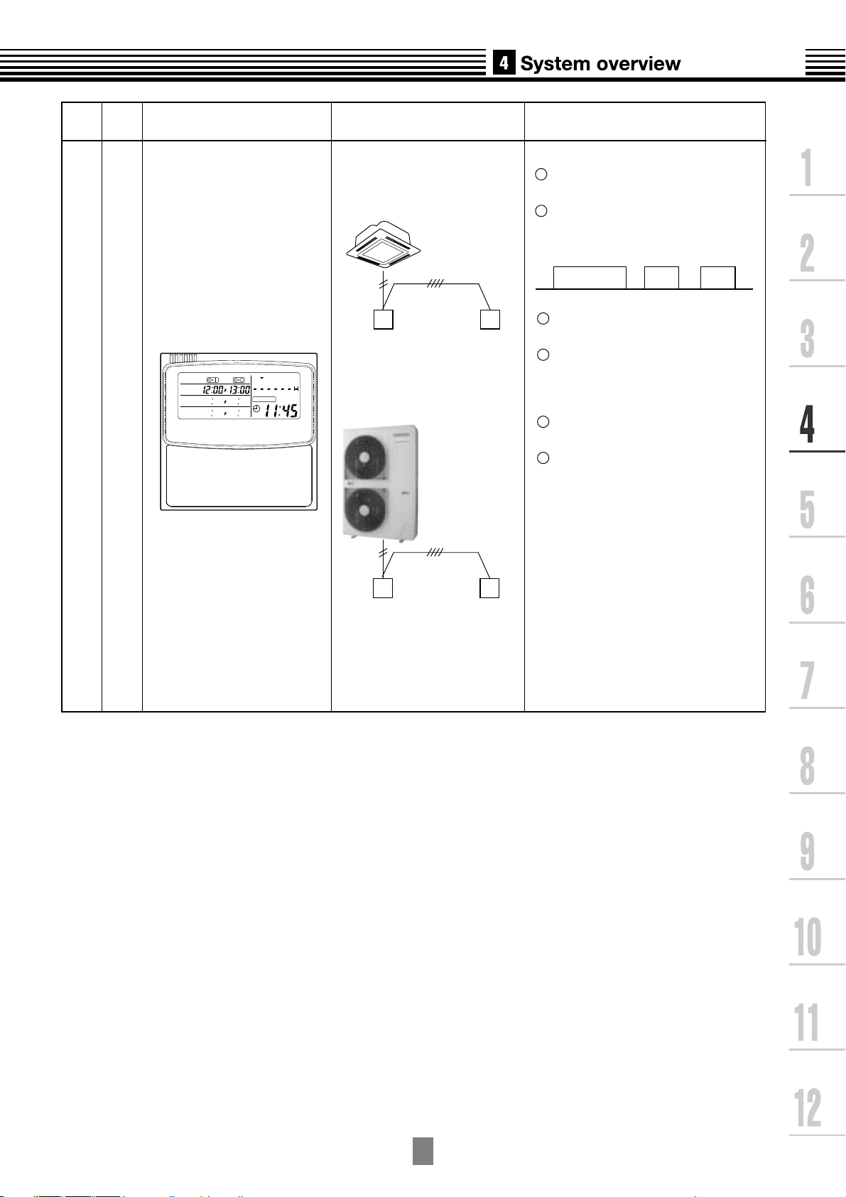
RBC-EXW21E2
Connected to central
remote controller or
wired remote controller
Wired
remote controller
Weekly
timer
Outdoor unit
Central
remote controller
Weekly
timer
Weekly schedule operation
Setting different start / stop time for each
day of the week
ON / OFF can be set 3 times
a day.
1
2
3
Two different schedules for a
week can be specified.
(Summer schedule and winter
schedule, etc.)
4
5
If power supply fails, the setting
contents are stored in the memory for
100 hours.
6
"CHECK" "PROGRAM" "DAY"
button copying of settings easy.
"CANCEL" "DAY" button enables
holiday setting.
WEEKLY TIMER
ERROR
SuMoTuWeThFr Sa
PROGRAM1
PROGRAM2
PROGRAM3
ON
8:00 12:00 13:00 18:00 19:00 21:00
OFF ON OFF ON OFF
5
-1
For indoor unit, the capacity code is decided for each capacity rank.
NOTE :
Capacity rank : Correspondence to Btu/h. Capacity code : Correspondence to Horsepower.
For outdoor unit, maximum No. of connectable indoor units and total capacity code of indoor units
are decided.
Capacity rank type
Capacity code
007
0.8
009
1
012
1.25
015
1.7
018
2
024
2.5
030
3.2
036
4
048
5
027
3
Outdoor unit
Capacity code of
outdoor unit
Max. No. of
indoor units
Total capacity code
of indoor units
MCY-MAP0401HT
MCY-MAP0401HT2D
4
5
6
6
8
9
3.2 to 5.2
4.0 to 6.5
4.8 to 7.8
1
2
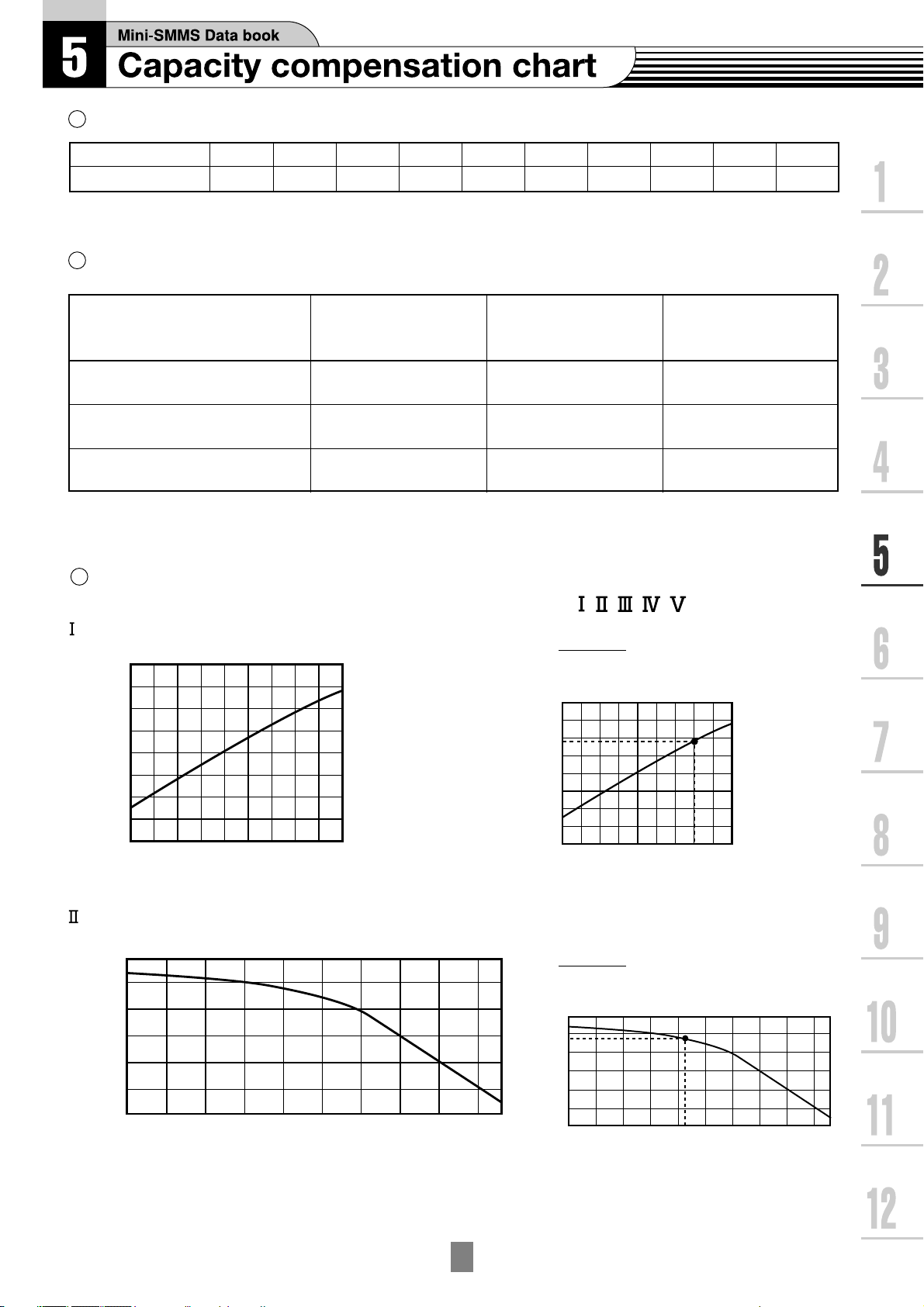
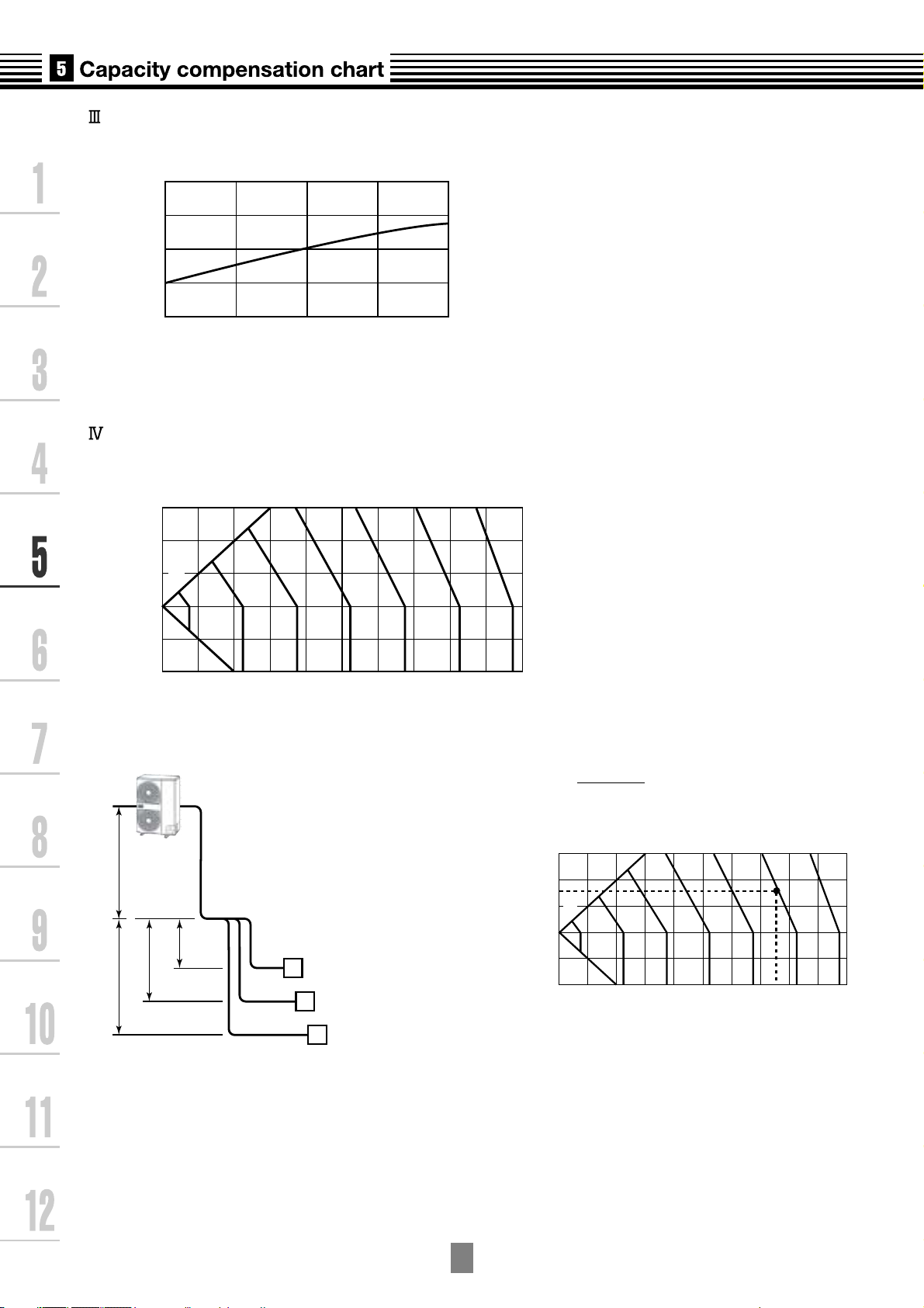
5-1. Cooling/heating capacity characteristics
Cooling capacity calculation method :
Required cooling capacity = Cooling capacity x Factor ( , , , , *
1
) kW
Indoor air wet bulb temperature vs. capacity correction value
1
Indoor air wet bulb temp. (
o
C)
Capacity correction value
15
1.2
1.1
1.0
0.9
0.8
20 24
Outdoor air dry bulb temperature vs.capacity correction value
Indoor air wet bulb temp. (
o
C)
Capacity correction value
15
1.2
1.1
1.0
0.9
0.8
20 24
(Example)
Design Outdoor conditions : 17
o
C DB
Capacity correction value : 1.14
Outdoor air dry bulb temp. (
o
C)
Capacity correction value
-
50 51015202530354043
0.9
1
1.1
1.2
Outdoor air dry bulb temp. (
o
C)
Capacity correction value
-
50 51015202530354043
0.9
1
1.1
1.2
MCY-MAP0501HT
MCY-MAP0501HT2D
MCY-MAP0601HT
MCY-MAP0601HT2D
(Example)
Design Indoor conditions : 22
o
C WB
Capacity correction value : 1.09
*
1 : Coefficient to use for correction of outdoor unit capacity when total capacity of the indoor
units are not equal to the outdoor unit capacity.
5
-2
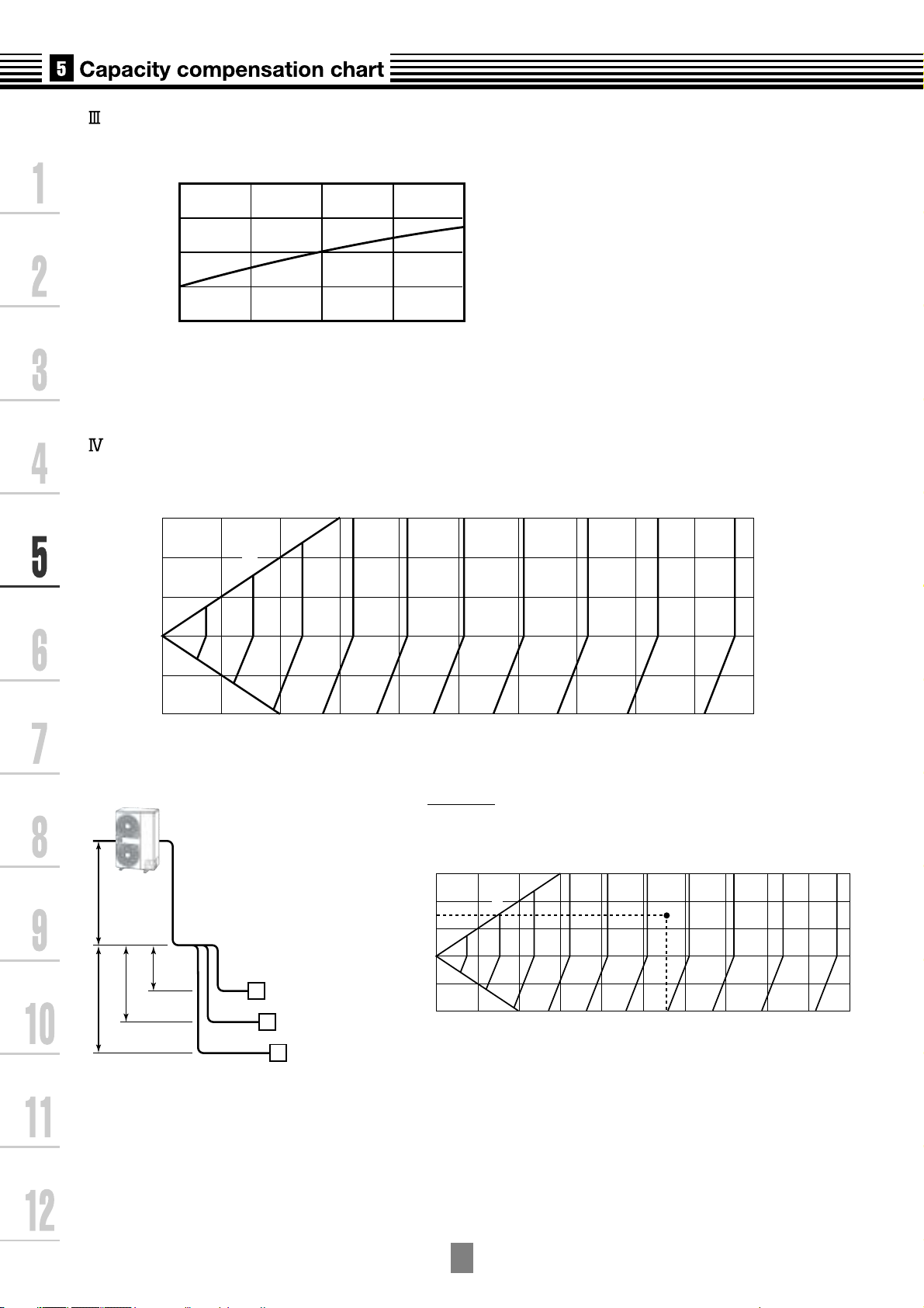
Air flow variation ratio of indoor unit vs. capacity correction (For concealed duct type only)
Capacity correction value
1.1
1.0
0.9
80 90 100 110 120
Air flow variation ratio (%)
30
20
10
0
-
10
-
20
010203040
Pipe length (Equivalent length) L(m)
Hight of outdoor unit H (m)
50 60 70 80 90 100
100%
98
96
94
92
90
88
86
84
82
Outdoor unit
Indoor unit
L is the longest one of
(Ll + a, Ll + b, Ll + c)
H = ho +
(Largest one of ha, hb, and hc)
A
ha
hb
hc
ho Ll
a
b
c
B
C
30
20
10
0
-
10
-
20
010203040
Pipe length (Equivalent length) L(m)
Hight of outdoor unit H (m)
50 60 70 80 90 100
100%
98
96
94
92
90
88
86
84
82
(Example)
Design Pipelength : 55m
Height of outdoor unit : 15m
Capacity correction value: 89%
Connecting pipe length and lift difference between indoor and outdoor units vs. capacity correction value
5
-3
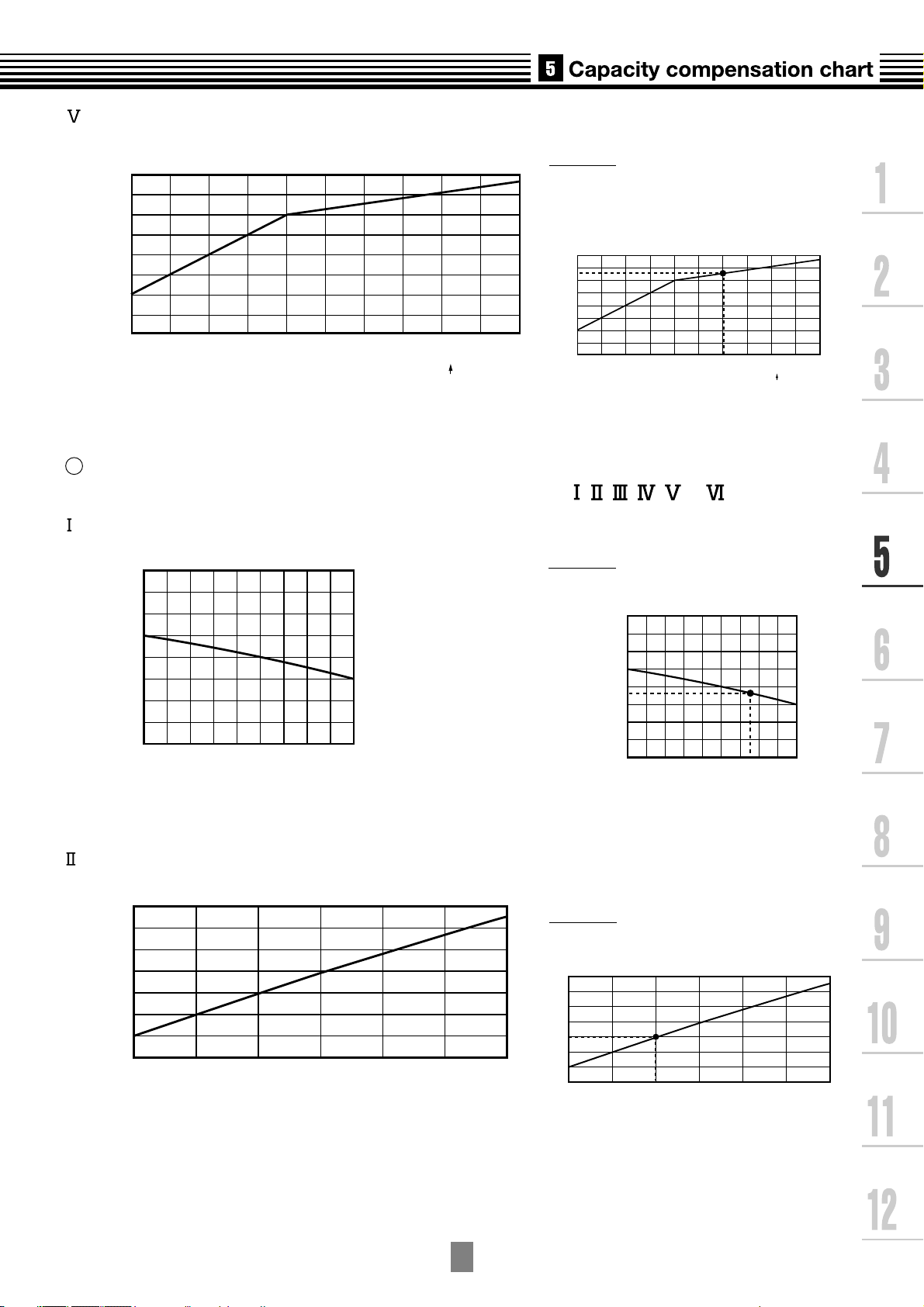
Correction of outdoor unit diversity
Heating capacity calculation method :
Required heating capacity = Heating capacity x Factor ( , , , , *
1
, *
2
) kW
Indoor air dry bulb temperature vs. capacity correction value
Outdoor air wet bulb temperature vs. capacity correction value
2
Indoor air dry bulb temp. (
o
C)
Capacity correction value
0.8
15 20 24
0.9
1.0
1.1
1.2
(Example)
Design Outdoor unit : 5.0HP
Indoor units total capacity : 5.5HP
(Capacity ratio : 110%)
Capacity correction value : 1.03%
Indoor air dry bulb temp. (
o
C)
Capacity correction value
0.8
15 20 24
0.9
1.0
1.1
1.2
(Example)
Design Indoor conditions : 21.5
o
C DB
Capacity correction value : 0.98
(Example)
Design Outdoor conditions :
-
5
o
C WB
Capacity correction value : 0.8
Outdoor air wet bulb temp. (
o
C)
Capacity correction value
1.2
1.1
1
0.9
0.8
0.7
0.6
0.5
-
15
-
10
-
50 51015
Outdoor air wet bulb temp. (
o
C)
Capacity correction value
1.2
1.1
1
0.9
0.8
0.7
0.6
0.5
-
15
-
10
-
50 51015
1.1
1
0.9
0.8
0.7
80 80 100 110 120 130
Capacity correction value
Indoor units total capacity ratio (%)
Standard capacity ratio
1.1
1
0.9
0.8
0.7
80 80 100 110 120 130
Capacity correction value
Indoor units total capacity ratio (%)
Standard capacity ratio
*
1 : Coefficient to use for correction of outdoor unit capacity when total capacity of the indoor
units are not equal to the outdoor unit capacity.
*
2 : Refer to item 3.
5
-4
Air flow variation ratio of indoor unit vs. capacity correction (For concealed duct type only)
Capacity correction value
Air flow variation ratio (%)
0.9
1.0
1.1
80 90 100 110 120
Connecting pipe length and lift difference between indoor and outdoor units vs. capacity correction value
Pipe length (Equivalent length) L (m)
Height of outdoor unit H (m)
30
99
98
97
96
95
94
20
10
0
-
10
-
20
0 102030 405060708090100
100%
Outdoor unit
Indoor unit
L is the longest one of
(Ll + a, Ll + b, Ll + c)
H = ho +
(Largest one of ha, hb, and hc)
A
ha
hb
hc
ho Ll
a
b
c
B
C
Pipe length (Equivalent length) L (m)
Height of outdoor unit H (m)
30
99
98
97
96
95
94
20
10
0
-
10
-
20
0 10 20304050607080 90100
100%
(Example)
Design Pipe length : 75m
Heigh of outdoor unit : 15m
Capacity correction value : 95.1%
5
-5
Correction of outdoor unit diversity
*
1 : Coefficient to use for correction of outdoor unit capacity when total capacity of the indoor
units are not equal to the outdoor unit capacity.
Capacity correction in case of frost on the outdoor heat exchanger in heating
Correct the heating capacity when frost was found on the outdoor heat exchanger.
Heating capacity = Capacity after correction of outdoor unit × Correction value of capacity resulted from frost
(Capacity after correction of outdoor unit : Heating capacity calculated in the above item 2.)
3
0.8
0.9
1.0
-
15
-
10
-
50 510
Outdoor air wet bulb temp. (
o
C)
Capacity correction value
Capacity correction in case of frost on the outdoor heat exchanger
Capacity calculation for each indoor unit
Capacity for each indoor unit
= Capacity after correction of outdoor unit x
Required standard capacity of indoor unit
Total value of standard indoor unit capacity
4
(Example)
Design Outdoor unit : 5HP
Indoor units total capacity : 4.5HP
(Capacity ratio : 90%)
Capacity correction value : 0.9%
1.1
1
0.9
0.8
0.7
80 90 100 110 120 130
Capacity correction value
Indoor units total capacity ratio (%)
Standard capacity ratio
1.1
1
0.9
0.8
0.7
80 90 100 110 120 130
Capacity correction value
Indoor units total capacity ratio (%)
Standard capacity ratio
5
-6
Rated conditions
Cooling :
Indoor air temperature 27
o
C DB/19.0
o
C WB, Outdoor air temperature 35
o
C DB
Heating :
Indoor air temperature 20
o
C DB, Outdoor air temperature 7
o
C DB/6
o
C WB
5
6
Operating temperature range
3025 28201510
-
10
-
5
0
5
10
15
20
25
30
35
40
45
Indoor air wet bulb temp. (
o
C)
In cooling time
Outdoor air dry bulb temp. (
o
C)
Continuously
operable
range
Usable range
(in pull down)
Indoor air dry bulb temp. (
o
C)
In heating time
Outdoor air wet bulb temp. (
o
C)
-
20
-
15
-
10
-
5
0
5
10
15
20
5 1015202530
Continuously
operable
range
Usable range
(in warming-up)
6
-1
Line
branching
system
Header
branching
system
Header
branching
system
after line
branching
Line
branching
system after
header
branching
Header
branching
system after
header
branching
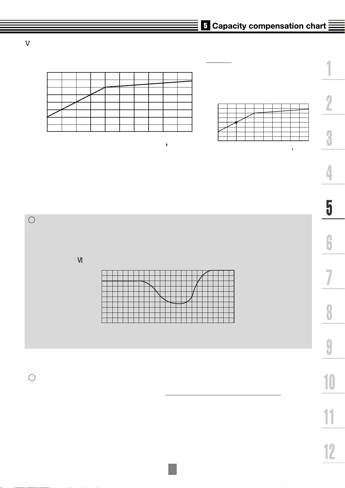
6-1. Free branching system
Line branching system
Header branching system
Header branching system after line branching
Line branching system after header branching
Header branching system after header branching
The above five branching systems are available to dramatically increase the flexibility of refrigerant piping design.
1
2
3
4
5
Outdoor unit
Branching joint
Remote
controller
Indoor unit
Branching header
Remote controller
Indoor unit
Outdoor unit
Branching joint
Remote
controller
Indoor unit
PMV
Kit
Branching header
Outdoor unit
Branching
joint
Remote
controller
Indoor
unit
Branching header
Outdoor unit
PMV
Kit
* In case of "PMV Kit"
* In case of "PMV Kit"
6
-2
6-2. Refrigerant piping length and piping size
A
Outdoor unit
Main
pipe
Branching header
Branching
pipe
Height
difference
between
Indoor and
outdoor unit
Equivalent length corresponded to farthest piping
Equivalent length corresponded to farthest piping after 1st branching Li
Indoor unit
Y-shape
branching joint
Height difference
between indoor units
1st branching
section
L2
L3
L4
L
ef
g
H1
H2
L1
ab cd
Branching pipe
Allowable length and height difference of refrigerant piping
1
Loading...