


Toshiba MMK-AP0243H, MMK-AP0123H, MMK-AP0073H, MMK-AP0183H, MMK-AP0093H DATA BOOK
...FILE NO. SVM-09059
SERVICE MANUAL
<High Wall Type>
MMK-AP0073H (IN) MMK-AP0093H (IN) MMK-AP0123H (IN) MMK-AP0153H (IN) MMK-AP0183H (IN) MMK-AP0243H (IN)
•This Service Manual describes contents of the new High Wall indoor unit.
For the outdoor unit, refer to the Manual with FILE NO. A03-009, A05-004, A05-015.
•The service parts will be supplied by TCTC.
PRINTED IN JAPAN, Dec.,2008 ToMo
|
CONTENTS |
|
SAFETY CAUTION ............................................................................................ |
3 |
|
1. |
CONSTRUCTION VIEWS (EXTERNAL VIEWS)......................................... |
8 |
2. |
WIRING DIAGRAM ..................................................................................... |
9 |
3. |
PARTS RATING ........................................................................................ |
10 |
4. |
REFRIGERATING CYCLE DIAGRAM ...................................................... |
40 |
5. |
CONTROL OUTLINE ................................................................................ |
41 |
6. |
APPLIED CONTROL ................................................................................ |
48 |
7. |
TROUBLESHOOTING .............................................................................. |
55 |
8. |
CONFIGURATION OF CONTROL CIRCUIT .......................................... |
129 |
9. |
HOW TO REPLACE MAIN PARTS .......................................................... |
131 |
10. |
REPLACEMENT OF SERVICE INDOOR P.C. BOARD .......................... |
139 |
11. |
EXPLODED VIEWS AND PARTS LIST .................................................. |
144 |
2
SAFETY CAUTION
The important contents concerned to the safety are described on the product itself and on this Service Manual.
Please read this Service Manual after understanding the described items thoroughly in the following contents, and keep them.
|
WARNING |
|
|
|
|
|
Before troubleshooting or repair work, check the earth wire is connected to the earth |
|
|
terminals of the main unit, otherwise an electric shock is caused when a leak occurs. |
|
Check earth wires. |
If the earth wire is not correctly connected, contact an electric engineer for rework. |
|
|
|
|
|
Do not modify the products. |
|
|
Do not also disassemble or modify the parts. It may cause a fire, electric shock or injury. |
|
Prohibition of modification. |
|
|
|
|
|
|
For spare parts, use those specified ( ). |
|
|
If unspecified parts are used, a fire or electric shock may be caused. |
|
Use specified parts. |
: For details, refer to the parts list. |
|
|
|
|
|
Before troubleshooting or repair work, do not bring a third party (a child, etc.) except |
|
|
the repair engineers close to the equipment. |
|
Do not bring a child |
It causes an injury with tools or disassembled parts. |
|
Please inform the users so that the third party (a child, etc.) does not approach the equipment. |
||
close to the equipment. |
||
|
|
|
|
Connect the cut-off lead cables with crimp contact, etc, put the closed end side |
|
|
upward and then apply a water-cut method, otherwise a leak or production of fire is |
|
Insulating measures |
caused at the users’ side. |
|
|
|
|
|
When repairing the refrigerating cycle, take the following measures. |
|
|
1) Be attentive to fire around the cycle. When using a gas stove, etc, be sure to put out fire |
|
|
before work; otherwise the oil mixed with refrigerant gas may catch fire. |
|
|
2) Do not use a welder in the closed room. |
|
No fire |
When using it without ventilation, carbon monoxide poisoning may be caused. |
|
|
3) Do not bring inflammables close to the refrigerant cycle, otherwise fire of the welder may |
|
|
catch the inflammables. |
|
|
|
|
|
Check the used refrigerant name and use tools and materials of the parts which |
|
|
match with it. |
|
|
For the products which use R410A refrigerant, the refrigerant name is indicated at a |
|
|
position on the outdoor unit where is easy to see. To prevent miss-charging, the route of the |
|
|
service port is changed from one of the former R22. |
|
|
For an air conditioner which uses R410A, never use other refrigerant than R410A. |
|
|
For an air conditioner which uses other refrigerant (R22, etc.), never use R410A. |
|
|
If different types of refrigerant are mixed, abnormal high pressure generates in the |
|
|
refrigerating cycle and an injury due to breakage may be caused. |
|
|
Do not charge refrigerant additionally. |
|
|
If charging refrigerant additionally when refrigerant gas leaks, the refrigerant composition in |
|
|
the refrigerating cycle changes resulted in change of air conditioner characteristics or |
|
|
refrigerant over the specified standard amount is charged and an abnormal high pressure is |
|
|
applied to the inside of the refrigerating cycle resulted in cause of breakage or injury. |
|
Refrigerant |
Therefore if the refrigerant gas leaks, recover the refrigerant in the air conditioner, execute |
|
vacuuming, and then newly recharge the specified amount of liquid refrigerant. In this time, |
||
|
||
|
never charge the refrigerant over the specified amount. |
|
|
When recharging the refrigerant in the refrigerating cycle, do not mix the refrigerant |
|
|
or air other than R410A into the specified refrigerant. |
|
|
If air or others is mixed with the refrigerant, abnormal high pressure generates in the |
|
|
refrigerating cycle resulted in cause of injury due to breakage. |
|
|
After installation work, check the refrigerant gas does not leak. |
|
|
If the refrigerant gas leaks in the room, poisonous gas generates when gas touches to fire |
|
|
such as fan heater, stove or cocking stove though the refrigerant gas itself is innocuous. |
|
|
Never recover the refrigerant into the outdoor unit. |
|
|
When the equipment is moved or repaired, be sure to recover the refrigerant with recover- |
|
|
ing device. The refrigerant cannot be recovered in the outdoor unit; otherwise a serious |
|
|
accident such as breakage or injury is caused. |
|
|
|
3
|
WARNING |
|
After repair work, surely assemble the disassembled parts, and connect and lead the |
|
removed cables as before. Perform the work so that the cabinet or panel does not |
|
catch the inner cables. |
Assembly/Cabling |
If incorrect assembly or incorrect cable connection was done, a disaster such as a leak or |
|
fire is caused at user’s side. |
|
|
|
After the work has finished, be sure to use an insulation tester set (500V megger) to |
|
check the resistance is 2MW or more between the charge section and the non-charge |
|
metal section (Earth position). |
Insulator check |
If the resistance value is low, a disaster such as a leak or electric shock is caused at user’s |
|
side. |
When the refrigerant gas leaks during work, execute ventilation.
|
If the refrigerant gas touches to a fire, poisonous gas generates. A case of leakage of the |
Ventilation |
refrigerant and the closed room full with gas is dangerous because a shortage of oxygen |
occurs. Be sure to execute ventilation. |
When checking the circuit inevitably under condition of the power-ON, use rubber gloves and others not to touch to the charging section.
If touching to the charging section, an electric shock may be caused.
Be attentive to electric shock
When the refrigerant gas leaks, find up the leaked position and repair it surely.
If the leaked position cannot be found up and the repair work is interrupted, pump-down and tighten the service valve, otherwise the refrigerant gas may leak into the room.
The poisonous gas generates when gas touches to fire such as fan heater, stove or cocking stove though the refrigerant gas itself is innocuous.
|
When installing equipment which includes a large amount of charged refrigerant |
|
such as a multi air conditioner in a sub-room, it is necessary that the density does |
Compulsion |
not the limit even if the refrigerant leaks. |
If the refrigerant leaks and exceeds the limit density, an accident of shortage of oxygen is caused.
|
For the installation/moving/reinstallation work, follow to the Installation Manual. |
|
|
If an incorrect installation is done, a trouble of the refrigerating cycle, water leak, electric |
|
|
shock or fire is caused. |
|
|
|
|
|
After repair work has finished, check there is no trouble. |
|
|
If check is not executed, a fire, electric shock or injury may be caused. For a check, turn off |
|
|
the power breaker. |
|
|
|
|
Check after rerair |
After repair work (installation of front panel and cabinet) has finished, execute a test |
|
run to check there is no generation of smoke or abnormal sound. |
||
|
||
|
If check is not executed, a fire or an electric shock is caused. Before test run, install the |
|
|
front panel and cabinet. |
|
|
|
|
|
Check the following items after reinstallation. |
|
|
1) The earth wire is correctly connected. |
|
|
2) The power cord is not caught in the product. |
|
Check after reinstallation |
3) There is no inclination or unsteadiness and the installation is stable. |
|
|
If check is not executed, a fire, an electric shock or an injury is caused. |
CAUTION
|
Be sure to put on gloves (*) and long-sleeved shirt during repair work. |
|
If not putting on gloves, an injury may be caused with the parts, etc. |
Put on gloves |
( ) Heavy gloves such as work gloves |
|
|
|
|
|
When the power was turned on, start to work after the equipment has been |
|
sufficiently cooled. |
Cooling check |
As temperature of the compressor pipes and others became high due to cooling/heating |
operation, a burn may be caused. |
|
|
|
4

• New Refrigerant (R410A)
This air conditioner adopts a new HFC type refrigerant (R410A) which does not deplete the ozone layer.
1. Safety Caution Concerned to New Refrigerant
The pressure of R410A is high 1.6 times of that of the former refrigerant (R22).
Accompanied with change of refrigerant, the refrigerating oil has been also changed.
Therefore, be sure that water, dust, the former refrigerant or the former refrigerating oil is not mixed into the refrigerating cycle of the air conditioner with new refrigerant during installation work or service work.
If an incorrect work or incorrect service is performed, there is a possibility to cause a serious accident.
Use the tools and materials exclusive to R410A to purpose a safe work.
2.Cautions on Installation/Service
(1)Do not mix the other refrigerant or refrigerating oil.
For the tools exclusive to R410A, shapes of all the joints including the service port differ from those of the former refrigerant in order to prevent mixture of them.
(2)As the use pressure of the new refrigerant is high, use material thickness of the pipe and tools which are specified for R410A.
(3)In the installation time, use clean pipe materials and work with great attention so that water and others do not mix in because pipes are affected by impurities such as water, oxide scales, oil, etc.
Use the clean pipes.
Be sure to brazing with flowing nitrogen gas. (Never use gas other than nitrogen gas.)
(4)For the earth protection, use a vacuum pump for air purge.
(5)R410A refrigerant is azeotropic mixture type refrigerant.
Therefore use liquid type to charge the refrigerant. (If using gas for charging, composition of the refrigerant changes and then characteristics of the air conditioner change.)
3.Pipe Materials
For the refrigerant pipes, copper pipe and joints are mainly used.
It is necessary to select the most appropriate pipes to conform to the standard.
Use clean material in which impurities adhere inside of pipe or joint to a minimum.
(1) Copper pipe
<Piping>
The pipe thickness, flare finishing size, flare nut and others differ according to a refrigerant type.
When using a long copper pipe for R410A, it is recommended to select “Copper or copper-base pipe without seam” and one with bonded oil amount 40mg/10m or less.
Also do not use crushed, deformed, discolored (especially inside) pipes. (Impurities cause clogging of expansion valves and capillary tubes.)
<Flare nut>
Use the flare nuts which are attached to the air conditioner unit.
(2)Joint
The flare joint and socket joint are used for joints of the copper pipe. The joints are rarely used for installation of the air conditioner. However clear impurities when using them.
5

4.Tools
(1)Required Tools for R410A
Mixing of different types of oil may cause a trouble such as generation of sludge, clogging of capillary, etc. Accordingly, the tools to be used are classified into the following three types.
1)Tools exclusive for R410A (Those which cannot be used for conventional refrigerant (R22))
2)Tools exclusive for R410A, but can be also used for conventional refrigerant (R22)
3)Tools commonly used for R410A and for conventional refrigerant (R22)
The table below shows the tools exclusive for R410A and their interchangeability.
Tools exclusive for R410A (The following tools for R410A are required.)
Tools whose specifications are changed for R410A and their interchangeability
|
|
|
|
R410A |
Conventional air |
|
|
|
|
air conditioner installation |
conditioner installation |
||
No. |
Used tool |
Usage |
|
|
|
|
Existence of |
Whether |
Whether new equipment |
||||
|
|
|
||||
|
|
|
new equipment |
conventional equipment |
can be used with |
|
|
|
|
for R410A |
can be used |
conventional refrigerant |
|
|
|
|
|
|
|
|
• |
Flare tool |
Pipe flaring |
Yes |
(Note 1) |
Yes |
|
|
|
|
|
|
|
|
‚ |
Copper pipe gauge for |
Flaring by conventional |
Yes |
(Note 1) |
(Note 1) |
|
|
adjusting projection margin |
flare tool |
|
|
|
|
|
|
|
|
|
|
|
ƒ |
Torque wrench |
Connection of flare nut |
Yes |
No |
No |
|
|
|
|
|
|
|
|
„ |
Gauge manifold |
Evacuating, refrigerant |
Yes |
No |
No |
|
|
|
|||||
… |
Charge hose |
charge, run check, etc. |
||||
|
|
|
||||
|
|
|
|
|||
|
|
|
|
|
|
|
† |
Vacuum pump adapter |
Vacuum evacuating |
Yes |
No |
Yes |
|
|
|
|
|
|
|
|
‡ |
Electronic balance for |
Refrigerant charge |
Yes |
Yes |
Yes |
|
|
refrigerant charging |
|
|
|
|
|
|
|
|
|
|
|
|
ˆ |
Leakage detector |
Gas leakage check |
Yes |
No |
Yes |
|
|
|
|
|
|
|
|
‰ |
Charging cylinder |
Refrigerant charge |
(Note 2) |
No |
No |
|
|
|
|
|
|
|
|
(Note 1) When flaring is carried out for R410A using the conventional flare tools, adjustment of projection margin is necessary. For this adjustment, a copper pipe gauge, etc. are necessary.
(Note 2) Charging cylinder for R410A is being currently developed.
General tools (Conventional tools can be used.)
In addition to the above exclusive tools, the following equipments which serve also for R22 are necessary as the general tools.
1)Vacuum pump
Use vacuum pump by attaching vacuum pump adapter.
2) |
Torque wrench |
8) |
Spanner or Monkey wrench |
3) |
Pipe cutter |
9) |
Hole core drill |
4) |
Reamer |
10) Hexagon wrench (Opposite side 4mm) |
|
5) |
Pipe bender |
11) |
Tape measure |
6) |
Level vial |
12) |
Metal saw |
7) |
Screwdriver (+, –) |
|
|
Also prepare the following equipments for other installation method and run check. |
|||
1) |
Clamp meter |
3) |
Insulation resistance tester |
2) |
Thermometer |
4) |
Electroscope |
6
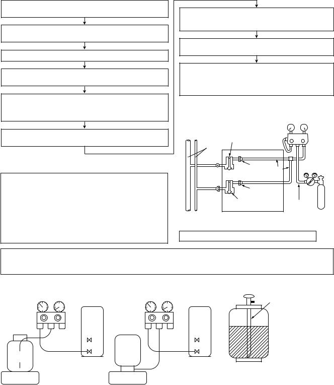
5. Recharge of Refrigerant
When recharge of the refrigerant is required, charge the new refrigerant with the specified amount in the procedure as described below.
Recover the refrigerant and check there is no refrigerant in the equipment.
Connect the charge hose to the packed valve service ports at gas side, liquid side, and balance side of the outdoor unit.
Connect the charge hose to vacuum pump adaptor.
Open the packed valves of the balance pipe fully at liquid and gas sides, and then return the valve at gas side a little to the closed side.
Open fully PMV of the outdoor unit.
•Turn on power of the outdoor unit.
•Short CN30 on I/F P.C. board of the outdoor unit.
•Turn off power of the outdoor unit within 2 minutes after short-circuiting.
Open fully the handle Low of the gauge manifold, and then turn on the power of vacuum pump for vacuuming.
1)Never charge the refrigerant over the specified amount.
2)Do not charge the additional refrigerant.
If charging refrigerant additionally when refrigerant gas leaks, the refrigerant composition in the refrigerating cycle changes resulted in change of air conditioner characteristics or refrigerant over the specified standard amount is charged and an abnormal high pressure is applied to the inside of the refrigerating cycle resulted in cause of breakage or injury.
When the pressure has lowered until indication of the compound gauge pointed -0.1MPa (–76cmHg), open fully the handle Low and turn off the power of vacuum pump.
Leave it as it is for 1 to 2 minutes and check the indicator of the compound gauge does not return.
Set the refrigerant cylinder on the electron balance, connect the charge hose to connecting ports of the cylinder and the electron gauge, and then charge the liquid refrigerant from the service port at liquid side. (Shield with the gauge manifold so that refrigerant does not flow to gas side.)
(Charge the refrigerant as below.)
|
Low- |
|
High- |
|
|
pressure gauge |
pressure gauge |
||
Connected to |
Valve fully closed |
|
|
|
indoor unit |
VL |
VH Gauge |
||
(gas side) |
||||
Main |
|
manifold |
||
Center unit |
|
|||
|
|
|||
pipe |
|
|
||
|
|
|
||
Brazed |
Service |
|
Reducing |
|
|
|
|||
|
port Ø6.4 |
|
valve |
|
Fully |
Copper pipe |
|
|
|
|
|
|
||
tightened |
|
|
||
|
Service port |
|
|
|
|
Valve fully closed |
Ø6.4 |
||
|
Copper pipe |
|||
|
(liquid side) |
|
|
|
Nitrogen Connected to other gas
terminal units
4mm-hexagonal wrench is required.
1)Set the equipment so that liquid refrigerant can be charged.
2)When using a cylinder with siphon pipe, liquid can be charged without inversing the cylinder.
[ Cylinder with siphon ]
Gauge manifold
OUTDOOR unit
Refrigerant
cylinder
[ Cylinder without siphon ]
Gauge manifold |
Siphon |
|
OUTDOOR unit |
cylinder Refrigerant
Electronic |
Electronic |
R410A refrigerant is consisted with HFC mixed refrigerant. |
balance |
balance |
Therefore if the refrigerant gas is charged, the composition |
|
|
|
|
|
of the charged refrigerant changes and characteristics of |
|
|
the equipment changes. |
|
|
|
6. Environment
Use “Vacuum pump method” for an air purge (Discharge of air in the connecting pipe) in installation time.
•Do not discharge flon gas into the air to protect the earth environment.
•Using the vacuum pump method, clear the remained air (Nitrogen, etc.) in the unit. If the air remains, the pressure in the refrigerating cycle becomes abnormally high and an injury and others are caused due to burst.
7

1. CONSTRUCTION VIEWS (EXTERNAL VIEWS)
1-1. Indoor Unit
Model: MMK-AP0073H (IN), MMK-AP0093H (IN), MMK-AP0123H (IN), MMK-AP0153H (IN), MMK-AP0183H (IN), MMK-AP0243H (IN)
1050
Front panel |
Air filter |
Air inlet |
320
73.5 |
|
|
7 |
50 |
Heat exchanger |
|
||
Knock out system |
|
|
228
|
73.5 |
50 |
7 |
|
Knock out system
50
Installation plate hanger |
72 |
78 |
|
|
204
132 |
568 |
200 |
150 |
56 |
24 |
||
|
|
|
|
|
|
|
|
Wireless remote controller
|
163 |
82 |
26 |
Installation plate hanger |
Remote controller holder |
|
|
|
|
Connecting pipe (0.39m) |
|
Drain hose |
Connecting pipe (0.44m) |
||
(07, 09, 12 series; |
9.5mm |
|
(0.5mm) |
(07, 09, 12 series; 6.4mm |
|
15, 18 series; 12.7mm |
|
|
15, 18 series; 6.4mm |
||
24 series; 15.9mm) |
|
|
|
24 series; 9.5mm) |
|
132 |
|
|
786 |
|
132 |
|
|
235 |
235 |
|
|
|
|
215 |
215 |
|
|
85 |
|
Hanger |
|
|
23 |
|
|
|
|
||
320 |
|
|
|
|
|
40 |
|
|
|
|
40 |
|
|
Hanger |
Hanger |
|
|
47 |
215.5 |
262.5 |
262.5 |
153.5 |
109 |
Center line |
|
Instrallation plate outline |
8
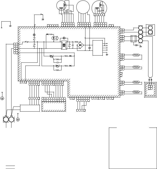
2. WIRING DIAGRAM
Model: MMK-AP0073H (IN), MMK-AP0093H (IN), MMK-AP0123H (IN),
MMK-AP0153H (IN), MMK-AP0183H (IN), MMK-AP0243H (IN)
|
|
|
|
|
|
Pulse motor valve |
|
|
Louver motor |
|
|
|
|
|
|
|
|
|
|||
|
|
|
|
|
|
|
|
|
Fan |
|
|
|
|
|
|
|
|
|
|
|
|
|
|
|
|
|
|
|
|
|
motor |
|
|
|
|
|
|
|
|
|
|
|
|
|
|
|
|
BLK |
|
|
|
|
|
|
5 4 3 2 1 |
|
|
|
|
|
|
|
|
|
|
|
|
|
|
|
F |
|
|
|
|
|
|
|
|
|
|
|
|
|
|
|
|
|
|
|
|
|
|
RED BRW BLU ORN YEL WHI |
BLU YEL WHI BLK |
RED |
YEL YEL YEL YEL WHI |
|
|
|
|
|
|
|
|
|
|
||
GRN & YEL |
Heat |
|
|
S |
|
|
|
|
|
|
|
|
|
|
|
|
|||||
|
|
|
|
HBS |
6 5 4 3 2 1 |
6 5 4 3 |
1 |
6 5 4 3 2 |
|
|
|
|
|
|
|
Outdoor unit |
|||||
|
exchanger |
|
CN22 |
|
|
|
|
|
|
|
|
||||||||||
|
|
|
|
|
|
|
|
|
|
|
|
|
|
||||||||
|
|
|
|
1 2 3 4 5 |
6 5 4 3 2 1 |
6 5 4 3 |
1 |
6 5 4 3 2 1 |
1 2 |
|
|
|
|
U1 |
|
U1 |
|||||
|
|
|
|
|
|
|
|
|
|
||||||||||||
|
|
|
|
|
|
CN50 |
|
CN82 |
CN210 |
|
|
CN44 |
CN40 |
1 |
1 |
BLU |
|
|
|||
|
|
|
|
|
|
|
|
|
|
U2 |
|
U2 |
|||||||||
|
|
|
|
|
|
(WHI) |
|
(BLU) |
(WHI) |
|
|
(BRW) (BLU) |
2 |
2 |
BLU |
|
|
||||
|
|
F301, Fuse |
|
|
|
|
|
|
|
|
|
CN41 |
3 |
3 |
BLK |
|
B |
|
|
||
|
CN67 |
|
T3.15A |
|
|
|
|
|
|
|
|
|
|
|
|
|
|||||
|
|
250V~ |
|
|
|
|
|
|
|
|
|
(BLU) |
2 |
|
WHI |
|
A |
|
|
||
RED |
(BLK) |
|
|
|
|
|
|
|
|
|
DC15V |
1 |
1 |
|
|
|
|||||
1 1 |
|
|
|
|
|
|
|
|
|
Power |
|
|
|
|
|
|
|
|
|||
|
|
|
|
|
|
|
|
|
|
|
|
|
|
|
|
|
|
||||
WHI 3 3 |
|
|
|
|
|
|
|
|
+ |
|
DC0V |
|
|
|
|
|
|
|
|||
|
|
|
|
|
|
|
|
|
supply |
|
DC12V |
|
|
Heat exchanger sensor |
|
|
|||||
|
|
|
|
|
|
|
|
|
|
|
circuit |
|
DC7V |
|
|
|
|
||||
|
5 |
|
|
|
|
|
|
|
|
|
|
|
|
|
|
|
BLK |
(TC1) |
|
|
|
|
|
|
|
|
|
|
|
|
|
|
|
|
|
1 |
1 |
|
|
|
|
||
|
|
|
|
|
|
|
|
|
|
|
|
|
|
CN100 |
|
|
|
|
|||
|
|
|
|
|
|
|
|
|
|
|
|
|
|
2 |
|
|
|
|
|
|
|
|
|
|
|
|
|
|
|
|
|
|
|
|
|
(BRW) |
|
BLK |
|
|
|
|
|
|
|
|
|
|
|
|
|
|
|
|
|
|
|
3 |
3 |
|
|
|
|
||
|
|
|
|
|
|
|
|
|
|
|
|
|
|
|
|
|
Heat exchanger sensor |
|
|
||
|
|
|
|
|
|
|
|
|
|
|
|
|
|
|
|
|
BLK |
(TC2) |
|
|
|
|
|
|
|
|
|
|
|
|
|
|
|
|
|
CN101 |
1 |
1 |
|
|
|
|
|
|
|
|
|
|
|
|
|
|
Control P.C. board |
|
|
(BLU) |
2 |
2 |
BLK |
|
|
|
|
||
|
|
|
|
|
|
|
|
|
|
|
CN103 |
1 |
|
|
|
|
|
|
|||
|
|
|
|
CN81 |
CN213 |
|
|
for indoor unit |
|
|
|
TF |
|
|
|
|
|||||
|
|
|
|
|
|
|
|
(GRN) |
2 |
|
|
|
|
|
|||||||
|
|
|
|
(BLK) |
|
(WHI) |
|
|
(MCC-1510) |
|
|
|
|
|
Heat exchanger sensor |
|
|
||||
|
|
|
|
|
|
|
|
|
|
|
|
|
|
|
|
|
BLK |
(TCJ) |
WHI |
BLK |
|
|
CN309 |
1 |
3 |
1 2 3 4 5 |
1 2 3 4 5 6 7 8 9 10 |
|
|
|
|
|
|
CN102 |
1 |
1 |
|
||||||
|
|
|
|
|
|
|
|
|
|
|
|||||||||||
|
(YEL) |
|
|
1 2 3 4 5 |
2 3 4 |
7 8 9 10 |
|
|
|
|
|
|
(YEL) |
2 |
2 |
BLK |
|
|
|
1 2 |
|
|
|
|
|
WHI BRW YEL GRY PNK |
BLU BLU BLU |
BLU BLU BLU WHI |
|
|
|
|
|
|
|
|
|
Thermo sensor |
|
||||
|
|
|
|
|
|
|
|
|
|
|
|
|
BLK |
(TA) |
|
|
1 2 |
||||
|
|
|
|
|
|
|
|
|
|
|
|
|
|
|
|
|
|
|
|||
|
|
|
|
|
|
|
|
CN32 |
CN61 |
|
CN60 |
CN80 CN104 |
1 |
1 |
|
|
|
CN1 |
|||
|
|
|
|
|
|
|
|
(WHI) |
(YEL) |
|
(WHI) |
(GRN) (WHI) |
2 |
2 |
BLK |
|
|
(WHI) |
|||
|
|
|
|
1 2 3 4 5 |
8 7 6 5 4 3 2 |
1 2 |
1 2 3 4 5 6 |
1 2 3 4 5 6 |
|
1 2 3 |
|
|
|
|
|
Wired |
|||||
|
|
|
|
|
1110 9 8 7 6 5 4 3 2 1 |
Fan |
1 2 3 4 5 6 |
Option |
PNL/EMG |
|
|
|
|
|
|||||||
|
|
|
|
|
|
|
|
|
remote controller |
||||||||||||
|
|
|
|
|
Infrared rays receive |
drive |
|
|
|
|
|
|
|
|
|
|
(Sold separately) |
||||
|
|
|
|
|
|
|
|
|
|
|
|
|
|
|
|
|
|
|
|||
|
|
|
Flow selector unit |
and Indication parts |
|
|
|
|
|
|
|
|
|
|
|
|
|
|
|||
|
|
|
(Sold separately) |
(MCC-5044) |
|
|
1 2 3 4 |
HA |
|
|
|
|
|
|
|
|
|
|
|
||
|
|
|
|
|
|
|
|
|
|
|
|
|
|
|
|
|
|
|
|
||
|
GRN & YEL |
|
|
|
|
|
|
|
|
|
|
|
|
|
|
|
|
|
|||
R(L) S(N)
Power supply single phase 220–240V, 50Hz
220V, 60Hz
1. indicates the terminal block.
Letter at inside indicates the terminal number.
2.A dotted line and broken line indicates the wiring at site.
3. indicates the control P.C. board.
Color identification
BRW : BROWN RED : RED WHI : WHITE YEL : YELLOW BLU : BLUE BLK : BLACK GRY : GRAY PNK : PINK ORN : ORANGE
GRN & YEL: GREEN & YELLOW GRN : GREEN
9
3. PARTS RATING
3-1. Parts Rating
No. |
Parts Name |
Type |
|
Specications |
|
|
|
|
|
|
|
1 |
Fan motor (for indoor) |
ICF-340-30-4 |
Output (Rated) 30W, 280-340V DC |
||
MF-340-30-1RT |
|||||
|
|
|
|
||
|
|
|
|
||
2 |
Grille motor |
MP24Z3T |
Output (Rated) 1W, 16 poles DC |
||
|
|
|
|
|
|
3 |
Thermo. Sensor (TA sensor) |
318mm |
10kΩ |
at 25°C |
|
|
|
|
|
|
|
4 |
Heat exchanger sensor (TC1 sensor) |
Ø4,600mm |
10kΩ |
at 25°C |
|
|
|
|
|
|
|
5 |
Heat exchanger sensor (TC2 sensor) |
Ø6,800mm |
10kΩ |
at 25°C |
|
|
|
|
|
|
|
6 |
Heat exchanger sensor (TCJ sensor) |
Ø6,800mm |
10kΩ |
at 25°C |
|
|
|
|
|
||
7 |
PMV motor |
EDM-MD12TF |
12V DC |
||
|
|
|
|
|
|
3-2. Name of Each Part
Model: MMK-APXXX3H
Air outlet / Louver |
|
|
|
Air inlet grille |
|
|
|||
Change the direction of the air to be |
|
|
Air in the room is sucked from here. |
|
discharged according to cool/heat mode. |
|
|
|
|
|
|
|
|
|
|
|
|
|
|
Air filter |
|
|
|
Earth screw |
|
|
|||
Removes dirt or dust. |
|
|
Earth screws are provided |
|
(Provided in the air inlet grille) |
|
|
in the electric parts box. |
|
10
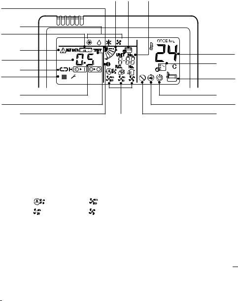
3-3. Parts Name of Remote Controller
n Display section
In the display example, all indicators are displayed for the explanation. In reality only, the selected contents are indicated.
•When turning on the main power switch and leak breaker at the first time, SETTING flashes on the display part of the remote controller.
•While this display is flashing, the model is being automatically confirmed.
Accordingly, wait for a while after SETTING display has disappeared, and then use the remote controller.
9 20 19
Display section
TEMP. |
|
ON / OFF |
|
TIMER SET |
FAN |
MODE |
Operation |
|
|
|
|
TIME |
SAVE |
VENT |
section |
FILTER |
SWING/FIX |
UNIT LOUVER |
|
RESET TEST SET CL |
|
This remote controller can control the operation of Max. 8 indoor units.
8 |
|
|
|
|
1 |
2 |
|
|
|
4 |
3 |
|
17 |
10 |
5 |
|
|||
6 |
|
16 |
11 |
|
7 |
15 |
|
12 |
|
|
18 |
14 |
13 |
|
|
|
|
|
1 SETTING display
Displayed during setup of the timer etc.
2 Operation mode select display
The selected operation mode is displayed.
3 CHECK display
Displayed while the protective device works or a trouble occurs.
4 Timer time display
Time of the timer with H mark is displayed. (When a trouble occurs, the check code is displayed.)
5 Timer SET IN setup display
When pushing the Timer SET IN button, the display of the timer is selected in order of
[OFF] |
|
→ |
[OFF] repeat OFF timer → |
[ON] |
|
→ |
No display. |
|
6 Filter display
If “FILTER 


 ” is displayed, clean the air filter.
7 TEST run display
Displayed during a test run.
8 Louver position display (4-way Air Discharge Cassette, 2-way Air Discharge Cassette,
1-way Air Discharge Cassette, Under Ceiling and High Wall Type only (2H. 3H))
Displays louver position.
9 SWING display
Displayed during up/down movement of the louver.
10 Set up temperature display
The selected set up temp. is displayed.
11 Remote controller sensor display
Displayed while the sensor of the remote controller is used.
12 PRE-HEAT display (Heat-pump model only)
Displayed when the heating operation starts or defrost operation is carried out.
While this indication is displayed, the indoor fan stops or the mode enters in LOW.
13 No function display
Displayed if there is no function even if the button is pushed.
11
8 |
|
9 20 |
19 |
|
|
|
|
|
|
1 |
2 |
|
|
|
4 |
3 |
|
17 |
10 |
5 |
|
|||
6 |
|
16 |
11 |
|
7 |
15 |
|
12 |
|
|
18 |
14 |
13 |
|
|
|
|
|
14 Air volume select display
The selected air volume mode is displayed.
(AUTO) 
 (HIGH)
(MED.)  (LOW)
(LOW)
15 Louver Number display (exapmle:01, 02, 03, 04)
16 Operation ready display
Displayed when cooling or heating operation is impossible because the outdoor temperature goes out of the operable range.
17 Mode select control display
Displayed when pushing “Operation mode select 
 ” button while the operation mode is fixed to heating or cooling by the system manager of the air conditioner.
18 Louver lock display
(4-way Air Discharge Cassette Type 2H series only)
Displayed when there is a louver-locked unit in the group (including 1 indoor unit by 1 outdoor unit).
19 Unit Number display
Unit number of the indoor unit selected with the unit select button or abnormal indication of the indoor/outdoor unit.
20 Central control display
Displayed when the air conditioner is used under the central control in combination with a central control remote controller.
In case the remote controller is disabled by the central control system,  flashes.
The button operation is not accepted.
Even when you push ON/OFF, MODE, or TEMP. button, the button operation is not accepted.
(Settings made by the remote controller vary with the central control mode.
For details, refer to the Owner’s Manual of the central control remote controller.)
12
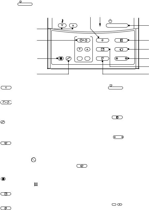
n Operation section
Push each button to select a desired operation.
• The details of the operation needs to be set up once, afterward, the air conditioner can be used by
|
pushing |
ON / OFF button only. |
|
|
|
|
|
|
|
|
|
|
|
|
|
1 |
8 |
|
|
|
|
|
|
TEMP. |
|
|
|
ON / OFF |
9 |
|
|
|
12 |
|
|
|
|
|
|
|
|
|
|
|
|
|
|
|
|
|
|
|
2 |
|
TIMER SET |
FAN |
MODE |
10 |
|
|
|
|
|
|
|
|
|
||
|
|
|
|
|
TIME |
SAVE |
VENT |
4 |
|
|
|
|
|
FILTER |
SET |
CL |
SWING/FIX |
UNIT LOUVER |
|
|
|
|
5 |
RESET TEST |
11 |
||||
|
|
|
|
|
|
|
|
||
|
|
|
3 |
|
|
|
|
|
6 |
|
|
|
|
|
|
|
|
7 |
|
1 |
FAN |
|
|
|
|
9 |
ON / OFF button |
|
|
|
button (Air volume select button) |
|
|
||||||
|
Selects the desired air volume mode. |
|
|
When the button is pushed, the operation |
|||||
2 |
TIMER SET |
|
|
|
|
starts, and it stops by pushing the button again. |
|||
|
button (Timer set button) |
|
|
When the operation has stopped, the operation |
|||||
|
TIMER SET button is used when the timer is set |
lamp and all the displays disappear. |
|||||||
|
up. |
|
|
|
|
|
10 |
MODE |
|
3 TEST |
button (Check button) |
|
|
|
button (Operation mode select |
||||
|
|
|
|
button) |
|
||||
|
The CHECK button is used for the check operation. |
|
Selects desired operation mode. |
||||||
During normal operation, do not use this button. |
11 |
UNIT LOUVER |
|||
4 |
VENT |
|
|
button (Unit/Louver select button) |
|
|
|
|
Selects a unit number (left) and louver |
||
button (Ventilation button) |
|
|
|||
Ventilation button is used when a fan which is |
|
number (right). |
|||
sold on the market is connected. |
|
|
UNIT: |
||
• |
If “No function |
” is displayed on the remote |
|
||
|
Selects an indoor unit when adjusting wind |
||||
|
controller when pushing the Ventilation |
VENT |
|
||
|
|
|
direction when multiple indoor units are |
||
|
|
|
|
|
|
button, a fan is not connected. |
controlled with one remote controller. |
|
5
6
7
8
FILTER
RESET button (Filter reset button)
Resets (Erases) “


 FILTER” display.
SAVE
button (Power save operation)
No function
SWING/FIX
button (Swing/Wind direction button)
Selects automatic swing or setting the louver direction.
•This function is not provided to Concealed Duct Standard Type, High Static Pressure Type, Floor Standing Cabinet Type,
Floor Standing Concealed Type or Slim Duct Type.
Operation lamp
Lamp is lit during the operation.
Lamp is off when stopped.
Also it flashes when operating the protection device or abnormal time.
LOUVER (4-way Air Discharge Cassette Type 2H series only):
Selects a louver when setting louver lock or wind direction adjustment independently.
12  TEMP. button (Set up temperature button)
Adjusts the room temperature.
Set the desired set temperature by pushing  TEMP.
TEMP.  or
or  TEMP.
TEMP.  .
.
OPTION :
Remote controller sensor
Usually the TEMP. sensor of the indoor unit senses the temperature. The temperature on the surrounding of the remote controller can also be sensed.
For details, contact the dealer from which you have purchased the air conditioner.
•In case that one remote controller controls the multiple indoor units, the setup operation is unavailable in group control.
13
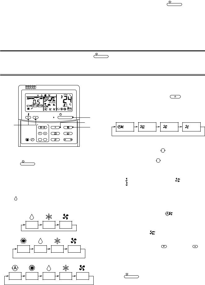
3-4. Correct Usage
•When you use the air conditioner for the first time or when you change the SET DATA value, follow the procedure below.
From the next time, the operation displayed on the remote controller will start by pushing the ON / OFF button only.
n Preparation
Turn on the main power switch and/or the leakage breaker.
• When the power supply is turned on, a partition line is displayed on the display part of the remote controller.
After the power supply is turned on, the remote controller does not accept an operation for approx. 1 minute, but it is not a failure.
REQUIREMENT
• While using the air conditioner, operate it only with ON / OFF button without turning off the main power switch and the leak breaker.
•When you use the air conditioner after it has not been used for a long period, turn on the power switch at least 12 hours before starting operation.
TEMP. ON / OFF
4 |
TIMER SET |
FAN |
MODE |
|
TIME |
SAVE |
VENT |
FILTER |
SET CL |
SWING/FIX |
UNIT LOUVER |
RESET TEST |
3 Select air volume with “ |
FAN |
” button. |
One push of the button, and the display changes in the order shown as follows.
3 |
1 |
|
|
|
|
|
2 |
AUTO |
HIGH |
MED. |
LOW |
||
|
||||||
|
|
Start
1 Push ON / OFF button.
The operation lamp goes on, and the operation starts.
2 Select an operation mode with the
MODE
“MODE  ” button.
One push of the button, and the display changes in the order shown as follows.
•“ DRY mode” function is not provided to Concealed Duct High Static Pressure Type.
•When air volume is “
 AUTO”, air volume differs according to the room temperature.
•In  DRY mode, “
 AUTO” is displayed and the air volume is LOW.
•In heating operation, if the room temperature is not heated sufficiently with VOLUME
“ LOW” operation, select “
 MED.” or “
 HIGH” operation.
•The temperature sensor senses temperature near the air inlet of the indoor unit, which differs from the room temperature depending on the installation condition.
Cooling only model |
A value of setting temperature is the measure |
||
of room temperature. (“ |
AUTO” is not |
||
|
|||
selectable in the FAN mode.)
DRY |
COOL |
FAN |
• |
Air volume of function is not provided to |
|
|
|
|
“Concealed Duct High Static Pressure Type” |
Heat-pump model |
|
but air speed “ HIGH” only is displayed. |
||
|
|
|||
|
|
|
|
|
4 Determine the set up temperature by |
|
|
HEAT |
|
DRY |
COOL |
FAN |
pushing the “TEMP. |
” or “TEMP. |
” |
|
button. |
|
|
||||
|
(Dehumidify) |
|
|
|
|
||
|
|
|
|
|
|
||
|
Heat Recovery model |
|
|
|
|
||
|
|
|
|
|
Stop |
|
|
AUTO |
HEAT |
DRY |
COOL |
FAN |
Push ON / OFF button. |
|
|
|
|
(Dehumidify) |
|
The operation lamp goes off, and the operation stops. |
|||
14
[In case of cooling]
• Start the cooling operation after approx. 1 minute.
[In case of heating (For Heat-pump model only)]
•The heating operation mode is selected in accordance with the room temperature and operation starts after approximately 3 to 5 minutes.
•After the heating operation has stopped, FAN operation may continue for approx. 30 seconds.
•When the room temperature reaches the set temperature, the super low wind is discharged and the air volume decreases excessively.
•During defrost operation, the fan stops so that cool air is not discharged. (“
 PRE-HEAT” is displayed.)
NOTE
When restarting the operation after stop
•When restarting the operation immediately after stop, the air conditioner does not operate for approx. 3 minutes to protect the machine.
Automatic Operation (Super Heat Recovery Type Only)
When you set the air conditioner in  mode or switch over from AUTO operation because of some settings change, it will automatically select either cooling, heating, or fan only operation depending on the indoor temperature.
3-5. Adjustment of Wind Direction
For best cooling and heating performance, adjust the louvers (adjustment of up/down wind direction) appropriately.
CAUTION
•If cooling operation is performed with downward air outlet, dew may fall on surface of the cabinet or the horizontal louver resulted in dripping.
•If heating operation is performed with horizontal air outlet, unevenness of temperature may increase in the room.
•Do not move the horizontal louver directly with hands; otherwise a trouble is caused. Select direction of the horizontal louver using SWING/FIX switch on the remote controller.
The horizontal louver does not stop immediately even if the switch is pushed. Adjusting the stop position, push the switch.
uFor all models
[In Cooling operation]
Use the louvers with horizontal set point.
[In Heating operation (For Heat-pump model only)]
Use the louvers with downward set point.
uFor Under Ceiling, 1-way Air Discharge Cassette, High Wall Type
[Right / Left air direction adjustment]
To change the air outlet direction to right or left side, set the vertical louver inside of the horizontal louver to the desired direction.
15
u4-way Air Discharge Cassette Type (1H series), Compact 4-way Type
•When the air conditioner is not operating, the louvers automatically direct downward.
•While the air conditioner is in ready status for heating, the louvers direct upward.
The swinging operation starts after heating ready status has been cleared, but “SWING  ” is displayed on the remote controller even if the status is ready to heating.
u4-way Air Discharge Cassette Type (2H series)
•When the air conditioner is not operating, the louvers automatically close.
•The louvers direct horizontally when heating begins, during defrost operation, or during the minimum operation after reaching the set temperature.
When you make a swing or air direction setting at this time, the remote controller display varies with the setting, but the louvers stay pointed straight out horizontally.
When the air conditioner starts heating, the louvers direct to the set direction.
•As the refrigerant recovery control for the outdoor units in the Modular Multi system works even if the outdoor units stop, in some cases, the louver of the stopped indoor unit may open for several minutes.
[In Cooling operation]
Use the louvers with horizontal set point.
[In Heating operation
(For Heat-pump model only)]
Use the louvers with downward set point.
For Cooling (Cool) |
For Heating (Heat) |
Direct the louvers horizontally. |
Direct the louvers downward. |
According to the shape or arrangement of the room, the cold air and hot air can be discharged for two directions or three directions. For details, contact the dealer.
16
|
TIMER SET |
FAN |
MODE |
|
TIME |
SAVE |
VENT |
FILTER |
SET CL |
SWING/FIX |
UNIT LOUVER |
RESET TEST |
Unit select button
1
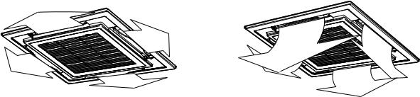
n How to set up the wind direction
1 Push |
SWING/FIX |
during operation. |
The wind direction changes for every push of the button.
[In HEAT operation]
Direct the louver (adjustment plate of up/down wind direction) downward.
If directing horizontally, hot air may not come to the foot.
Initial setup
[In COOL/DRY operation]
Direct the louver (adjustment plate of up/down wind direction) horizontally.
If directing it downward, the dew may form on the surface of the air discharge port and may drop down.
Initial setup
[In FAN operation]
Select a desired wind direction.
|
Initial setup |
n How to start swinging |
|
1 Push |
SWING/FIX |
, set the louver (adjustment plate |
|
of up/down wind direction) direction to the lowest position, and then push SWING/FIX again.
n How to stop swinging
1 Push |
SWING/FIX |
at a desired position while the |
louver is swinging.
SWING/FIX
• When  is pushed after that, wind direction can be set again from the highest position.
SWING/FIX
However, even if  is pushed while the louver is swinging, the louver position is displayed as follows and highest position of the louver may not be selected.
Display when swinging is stopped
FAN/HEAT |
COOL/DRY |
operation |
operation |
SWING/FIX
In this case, push  again two seconds later.
•In COOL/DRY operation, the louver does not stop as it directs downward.
If stopping the louver as it directs downward during swing operation, it stops after moving to the third position from the highest position.
Display when stopping the swing
FAN/HEAT |
COOL/DRY |
operation |
operation |
Unit select button
•When multiple indoor units are controlled with one remote controller, wind direction can be set for each indoor unit by selecting individually.
UNIT LOUVER
•To set wind direction individually, push  button to display an indoor unit number in the control group. Then set the wind direction of the displayed indoor unit.
SWING  is displayed and the up/down wind direction is automatically selected.
Display during swinging
Repeat
•When no indoor unit number is displayed, all indoor units in the control group can be controlled
simultaneously.
UNIT LOUVER
•Each time you push  button, the display changes as follows:
Unit No. 1-1  Unit No. 1-2
  Unit No. 1-3
No display  Unit No. 1-4
17
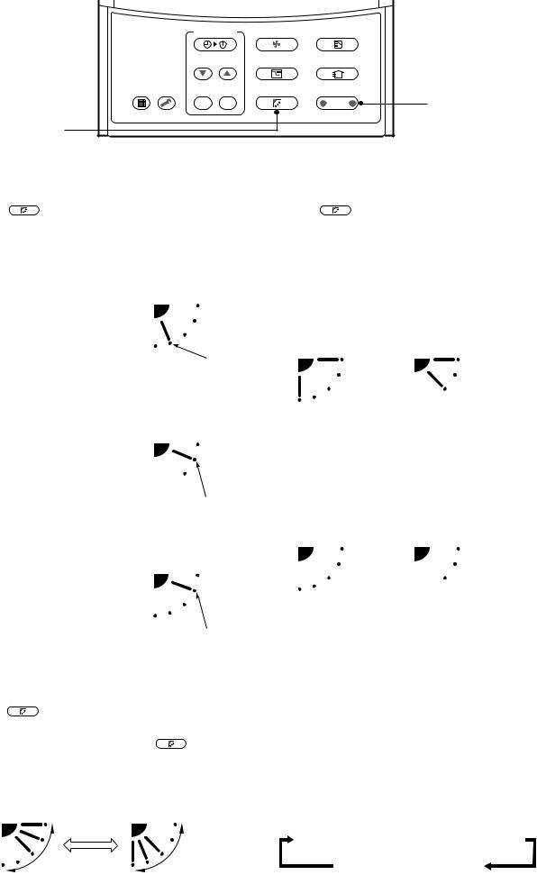
3-6. Timer Operation
•A type of timer operation can be selected from the following three types. (Setting of up to 168 hours is enabled.)
OFF timer |
: The operation stops when the time of timer has reached the set time. |
Repeat OFF timer : Every time, the operation stops after the set time has passed. |
|
ON timer |
: The operation starts when the time of timer has reached the set time. |
n Timer operation
1 |
TIMER SET |
FAN |
MODE |
|
|
TIME |
SAVE |
VENT |
|
||
|
2 |
||||
FILTER |
SET |
CL |
SWING/FIX |
UNIT LOUVER |
|
RESET TEST |
|||||
3 |
|
|
|
|
4 |
Set
1 Push TIMER SET button.
The timer display (type) changes for every push of the button.
|
OFF |
|
|
|
|
OFF |
|
|
|
ON |
|
|
|
|
|
|
|
|
|
|
|||
|
|
|
|
|
|
|
|
|
|
|
|
(OFF timer) |
(Repeat OFF timer) |
(ON timer) |
|||||||||
|
|
|
|
No display |
|
|
|
|
|||
|
|
|
|
|
|
|
|
||||
•SETTING and timer time displays flash.
2 Push |
TIME |
to select “SET TIME”. |
|
•For every push of  button, the set time increases in the unit of 0.5 hr (30 minutes).
Example of remote controller display
• In the case of 23.5 hours ( 1)
• In the case of 34 hours ( 2)
Number Time
of days
shows 1 day (24 hours).
shows 10 hours. (Total 34 hours).
When setting a time more than 24 hours for timer operation, timer time can be set in the unit of 1 hr.
The maximum set time is 168hr (7 days).
The remote controller displays the set time with time (between 0.5 and 23.5 hours) ( 1) or number of days and time (24 hours or more) ( 2) as shown below.
•For every push of  button, the set time decreases in the unit of 0.5 hr (30 minutes) (0.5 to 23.5 hours) or 1 hr (24 to 168 hours).
3
4
Push SET button.
•SETTING display disappears and timer time
display goes on, and  or
or  display flashes.
(When ON timer is activated, timer time, ON timer  are displayed and other displays disappear.)
Cancel of timer operation
CL
Push  button.
TIMER display disappears.
NOTE
• When the operation stops after the timer reached the preset time, the Repeat OFF timer resumes the operation by pushing  ON / OFF button and stops the operation after the reached the set time.
•When you push SWING/FIX while the OFF timer function of the air conditioner is active, the indication of the timer function disappears and then appears again after about 5 seconds.
This is due to normal processing of the remote controller.
18
3-7. Installation
Installation place
CAUTION
•Check that the air conditioner is not installed in a place subject to combustible gas leak. Accumulation of combustible gas around the unit may cause a fire.
•Drain the dehumidified water from the indoor unit and outdoor unit to a well-drained place.
•Do not put any obstacle near the air inlets and air outlet of the outdoor unit.
Doing so may hinder the radiation, which may reduce the performance or activate the protective device.
Electrical wiring
 WARNING
•Be sure to connect earth wire. (grounding work) Incomplete grounding cause an electric shock.
Do not connect ground wires to gas pipes, water pipes, lightning rods or ground wires for telephone wires.
CAUTION
•Make sure that a leakage breaker is connected.
Using the air conditioner without leakage breaker may cause electric shock.
•Use a leakage breaker with an appropriate capacity.
Be sure to use the rated voltage and an exclusive circuit for power supply of the air conditioner.
Do not install the air conditioner in the following places
•Do not install the air conditioner in any place within 1 m from a TV, stereo, or radio set.
If the unit is installed in such place, noise transmitted from the air conditioner affects the operation of these appliances.
•Do not install the air conditioner near a high frequency appliance (sewing machine or massager for business use, etc.), otherwise the air conditioner may malfunction.
•Do not install the air conditioner in a humid or oily place, or in a place where steam, soot, or corrosive gas is generated.
•Do not install the air conditioner in a salty place such as seaside area.
•Do not install the air conditioner in a place where a great deal of machine oil is used.
•Do not install the air conditioner in a place where it is usually exposed to strong wind such as in seaside area.
•Do not install the air conditioner in a place where sulfureous gas generated such as in a spa.
•Do not install the air conditioner in a vessel or mobile crane.
•Do not install the air conditioner in an acidic or alkaline atmosphere
(in a hot-spring area or near a chemicals factory, or in a place subject to combustion emissions). Corrosion may be generated on the aluminum fin and copper pipe of the heat exchanger.
•Do not install the air conditioner near an obstacle (air vent, lighting equipment, etc.) that disturbs discharge air. (Turbulent airflow may reduce the performance or disable devices.)
•Do not use the air conditioner for special purposes such as preserving food, precision instruments, or art objects, or where breeding animals or growing plants are kept. (This may degrade the quality of preserved materials.)
•Do not install the air conditioner over an object that must not get wet.
(Condensation may drop from the indoor unit at a humidity of 80% or more or when the drain port is clogged.)
•Do not install the air conditioner in a place where an organic solvent is used.
•Do not install the air conditioner near a door or window subject to humid outside air. Condensation may form on the air conditioner.
•Do not install the air conditioner in a place where special spray is used frequently.
Be careful with noise or vibrations
•Do not install the air conditioner in a place where noise by outdoor unit or hot air from its air outlet annoys your neighbors.
•Install the air conditioner on a solid and stable foundation so that it prevents transmission of resonating, operation noise and vibration.
•If one indoor unit is operating, some sound may be audible from other indoor units that are not operating.
19
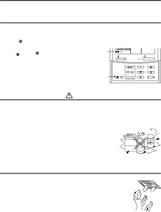
3-8. Maintenance
 WARNING
Be sure to turn off the main power switch prior to the maintenance.
•Please do not intend to do the daily maintenance and/or Air Filter cleaning by yourself.
Cleaning of the air filter and other parts of the air filter involves dangerous work in high places, so be sure to have a service person do it. Do not attempt it yourself.
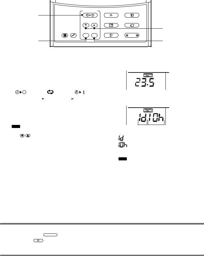
Cleaning of air filters
Clogging of air filters will reduce the cooling and heating performance.
1 When “ |
FILTER” appears on the remote controller, clean the air filters. |
|
|
|
|||
2 When the cleaning of air filters has been completed, |
1 |
|
|
|
|
||
FILTER |
button. “ |
FILTER” disappears. |
|
|
|
|
|
push RESET |
TEMP. |
|
|
ON / OFF |
|||
|
|
|
|
|
|
||
|
|
|
|
|
TIMER SET |
FAN |
MODE |
|
|
|
|
|
TIME |
SAVE |
VENT |
|
|
|
2 |
FILTER |
|
|
|
|
|
|
RESET TEST |
SET CL |
SWING/FIX |
UNIT LOUVER |
|
|
|
|
|
||||
CAUTION
Cleaning of unit
Clean the unit with a soft dry cloth.
If dirt cannot be removed with the dry cloth, use a cloth slightly dampened with lukewarm (under 40 °C) water.
Cleaning of remote controller
•Use a dry cloth to wipe the remote controller.
•A cloth dampened with cold water may be used on the indoor unit if it is very dirty.
• Never use a damp cloth on the remote controller.
• Do not use a chemically-treated duster for wiping or leave such materials |
Thinner |
|
on the unit for long. It may damage or fade the surface of the unit. |
||
|
• Do not use benzine, thinner, polishing powder, or similar solvents for cleaning.
These may cause the plastic surface to crack or deform.
Periodic check
Long-period use of the air conditioner may cause deterioration or failure of parts due to heat, humidity, dust, and operating conditions, or may cause poor drainage of dehumidified water.
If you do not plan to use the unit for more than 1 month
1) Operate the fan for 3 to 4 hours to dry inside the unit.
• Operate “FAN” mode.
2) Stop the air conditioner and turn off the main power switch or the circuit breaker.
Checks before operation
1) Check that the air filters are installed.
2)Check that the air outlet or inlet is not blocked.
3)Turn on the main power switch or the circuit breaker for the main power supply to the air conditioner.
20
NOTE
•For environmental conservation, it is strongly recommended that the indoor and outdoor units of the air conditioner in use be cleaned and maintained regularly to ensure efficient operation of the air conditioner.
When the air conditioner is operated for a long time, periodic maintenance (once a year) is recommended.
Furthermore, regularly check the outdoor unit for rust and scratches, and remove them or apply rustproof treatment, if necessary.
As a general rule, when an indoor unit is operated for 8 hours or more daily, clean the indoor unit and outdoor unit at least once every 3 months. Ask a professional for this cleaning/maintenance work.
Such maintenance can extend the life of the product though it involves the owner’s expense.
Failure to clean the indoor and outdoor units regularly will result in poor performance, freezing, water leakage, and even compressor failure.
Maintenance List
Part |
|
Check (visual/auditory) |
|
Maintenance |
|
|
|
|
|
|
|
Heat exchanger |
• |
Dust/dirt clogging, scratches |
• |
Wash the heat exchanger when it is clogged. |
|
|
|
|
|
|
|
Fan motor |
• |
Sound |
• |
Take appropriate measures when abnormal sound is generated. |
|
|
|
|
|
|
|
Filter |
• |
Dust/dirt, breakage |
• |
Wash the filter with water when it is contaminated. |
|
• |
Replace it when it is damaged. |
||||
|
|
|
|||
|
|
|
|
|
|
Fan |
• |
Vibration, balance |
• |
Replace the fan when vibration or balance is terrible. |
|
• |
Dust/dirt, appearance |
• |
Brush or wash the fan when it is contaminated. |
||
|
|||||
|
|
|
|
|
|
Air inlet/outlet grilles |
• |
Dust/dirt, scratches |
• |
Fix or replace them when they are deformed or damaged. |
|
|
|
|
|
|
|
Drain pan |
• |
Dust/dirt clogging, drain |
• |
Clean the drain pan and check the downward slope for |
|
|
contamination |
|
smooth drainage. |
||
|
|
|
|||
|
|
|
|
|
|
Ornamental panel, louvers |
• |
Dust/dirt, scratches |
• |
Wash them when they are contaminated or apply repair coating. |
|
|
|
|
|
|
WARNING
Re-Installation
Ask the dealer or an installation professional to re-install the air conditioner to a new place or move it to another place and to observe the following items.
If the air conditioner is inappropriately installed by yourself, it may cause electric shock or fire.
CAUTION
Be sure to clean the heat exchanger with pressurized water.
If an commercially detergent (strong alkaline or acid cleaning agent) is used, the surface treatment of the heat exchanger will be marred, which may degrade the self cleaning performance. For details, contact the dealer.
21
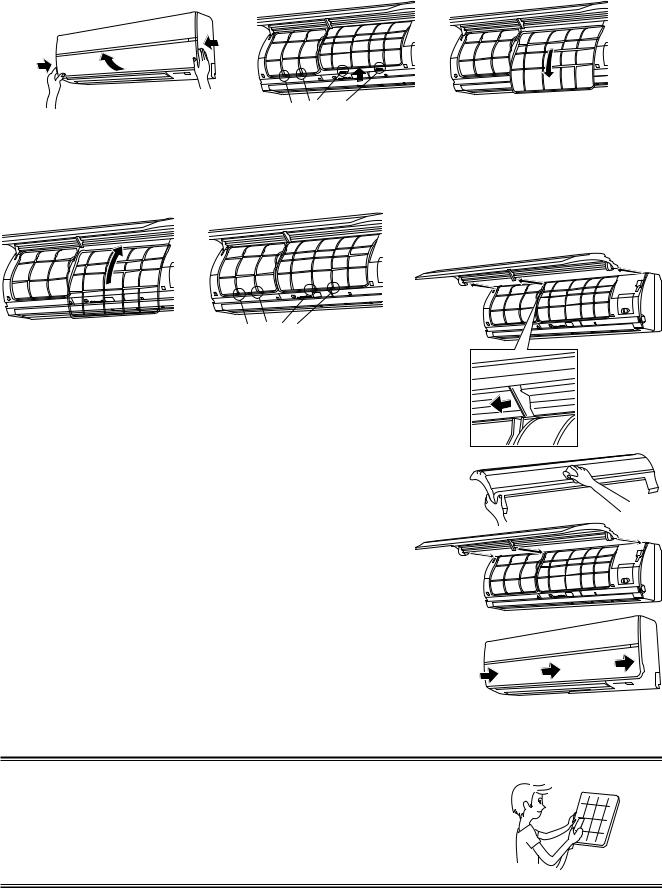
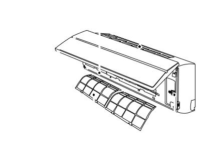
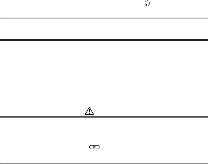
uHigh Wall Type
• Open the air inlet grille. Lift the air inlet grille up to the horizontal position.
•Take hold of the left and right handles of the air filter and lift it up slightly, then pull downward to take it out from the filter holder.
Filter holder
Return the air filter
•Insert the upper portion of air filter confirming to fit it is right and left edges on the indoor unit until it is firmly set.
•Close the air inlet grille.
Filter holder
Cleaning the air inlet grille
1.Remove the air inlet grille.
Hold the two sides of the air inlet grille and open upwards. Move the center arm to the left and remove the grille.
2.Wash it with water using a soft sponge or towel.
(Do not use metallic scrubbing brush or other hard brushes.)
•Use of such hard objects will cause scratches on the surface of the grille, and the metal coating to peel off.
•If very dirty, clean the air inlet grille with a neutral detergent for kitchen use, and rinse it off with water.
3.Wipe out water from the air inlet grille and dry it.
4.Fit the left and right arms of the air inlet grille to the shafts on the two sides of the air conditioner and push in completely, and then push in the center arm.
5.Check that the center arm has been completely inserted and close the air inlet grille.
•Push the arrow locations (Four) at the bottom of the air inlet grille to check whether the grill is completely closed.
NOTE
Cleaning of air filter
•For cleaning of air filter, use a cleaner or brush clean.
If stain is heavy, it is effective to wash the air filter in tepid water mixed with neutral detergent.
•After washing, rinse it well, and dry it in the shade.
•Install again the air filter which has been cleaned.
22

3-9. Air Conditioner Operations and Performance
Check before operation
•Check whether earth wire is disconnected or out of place.
•Check that air filter is installed to the indoor unit.
•Check that the air outlet or inlet is not blocked.
•Turn on the main power switch or the circuit breaker for the main power supply to the air conditioner.
 WARNING
Turn on the power switch 12 hours or more before starting before operation.
Heating capacity (for Heat-pump model only)
•For heating, a heat pump system which sucks in outside heat air and discharges it into the room is adopted. If temperature of the outside air lowers, the heating capacity decreases.
•When temperature of the outside air is low, it is recommended to use other heating equipment together.
Defrost operation during heating operation (for Heat-pump model only)
•If the outdoor unit has some frost during heating operation, the operation mode changes automatically to defrost mode to increase the heating effect (for approx. 2 to 10 minutes).
•During defrost operation, fans of the indoor and the outdoor units stop.
3 minutes protection
•The outdoor unit does not operate for approx. 3 minutes after air conditioner has been immediately restarted after stop, or power switch has been turned on. This is to protect the system.
Main power failure
•If a power failure occurred during the operation, all operations stop.
•When restarting the operation, push ON/OFF button again.
Fan rotation of stopped unit
•While other indoor units operate, the fan on indoor units on “stand-by” rotates to protect the machine once per approx. 1 hour for several minutes.
Protective device (High pressure switch)
The high pressure switch stops the air conditioner automatically when excessive load is applied to the air conditioner.
If the protective device works, the operation lamp keeps lit but the operation stops. When the protective device works, “ ” in the remote controller display part flash. The protective device may work in the following cases.
<Cooling operation>
•When the air inlet or air outlet of the outdoor unit is blocked.
•When strong wind blows continuously against the air outlet of the outdoor unit.
<Heating operation>
•When dust or dirt is excessively adhered to air filter of the indoor unit.
•When the air outlet of the indoor unit is blocked.
Cooling/heating operation of Modular Multi system air conditioner
•In Modular Multi system air conditioner, each indoor unit can be individually controlled. However, cooling operation and heating operation cannot be performed concurrently for the indoor units which are connected to one outdoor unit.
When cooling operation and heating operation are performed concurrently, the indoor unit which is performing cooling operation stops, and “ ” on the display is lit. The indoor unit which is performing heating operation continues operation. If the manager has fixed the setting to COOL or HEAT, other operation than set up one cannot be performed. When other operation than set up one is performed, “ ” on the display is lit and the operation stops.
Characteristics of heating operation (for Heat-pump model only)
•Hot air is not out immediately after the operation has started. After 3 to 5 minutes (differs according to room or outside temperature) has passed and the indoor heat exchanger has been warmed up, hot air blows out.
•During operation, the outdoor unit may stop if outside temperature becomes high.
•When other outdoor unit performs heating operation while the fan is operating, the fan operation may be stopped temporarily to prevent blowing of hot air.
Air conditioner operating conditions
For proper performance, operate the air conditioner under the following temperature conditions:
|
Outdoor temperature : –5°C to 43°C (Dry-bulb temp.) |
||
|
|
|
|
Cooling operation |
Room temperature |
: 21°C to 32°C (Dry-bulb temp.), 15°C to 24°C (Wet-bulb temp.) |
|
CAUTION Room relative humidity: less than 80 %. If the air conditioner operates |
|||
|
|||
|
in excess of this figure, the surface of the air conditioner may cause dewing. |
||
Heating operation |
Outdoor temperature : –15°C to 15.5°C (Wet-bulb temp.) |
||
Room temperature |
: 15°C to 28°C (Dry-bulb temp.) |
||
|
|||
|
|
|
|
If air conditioner is used outside of the above conditions, safety protection may operate.
23
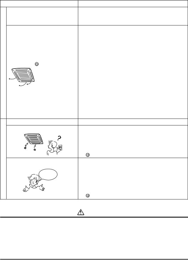
3-10. When the Following Symptoms are Found
Check the points described below before asking repair servicing.
Symptom
Outdoor unit • White misty cold air or water is out.
•Sometimes, noise “Pushu !” is heard.
Indoor unit |
• “Swish” sound is heard |
||
|
|
|
sometimes. |
failure.a |
|
• |
Slight “Pishi!” sound is heard. |
|
• |
Discharge air smells. |
|
|
|
||
It is not |
|
• |
“ ” indication is lit. |
|
|
|
|
|
|
• |
Sound or cool air is output |
|
|
|
from the stand by indoor unit. |
• |
When power of the air conditioner is turned |
||
|
on, “Ticktock” sound is heard. |
||
• |
Fan and louvers of the indoor unit moves |
||
|
when the unit is not operated. |
||
Operates or stops automatically. |
|||
Does not operate. |
|||
again. |
Silent |
|
|
Check |
Air is not cooled or warmed sufficiently. |
|
|
|
It’s strange. |
Cause
•Fan of the outdoor unit stops automatically and performs defrost operation.
•Solenoid valve works when defrost operation starts or finishes.
•When the operation has started, during the operation, or immediately after the operation has stopped, a sound such as water flows may be heard, and the operation sound may become larger for 2 or 3 minutes immediately after the operation has started.
They are flowing sound of refrigerant or draining sound of dehumidifier.
•This is sound generated when heat exchanger, etc. expand and contract slightly due to change of temperature.
•Various smell such as one of wall, carpet, clothes, cigarette, or cosmetics adhere to the air conditioner.
•When cooling operation cannot be performed because another indoor unit performs heating operation.
•When the manager of the air conditioner has fixed the operation to COOL or HEAT, and an operation contrary to the setup operation is performed.
•When fan operation stopped to prevent discharge of hot air.
•Since refrigerant is flowed temporarily to prevent stay of oil or refrigerant in the stand by indoor unit, sound of flowing refrigerant, “Kyururu” or “Shaa” may be heard or white steam when other indoor unit operates in HEAT mode, and cold air in COOL mode may be blow-out.
•Sound is generated when the expansion valve operates when power has been turned on.
•Intermittent operation of the fan with louvers open is sometimes carried out for the refrigerant recovery control of unoperated unit.
•Is the timer “ON” or “OFF”?
•Is it a power failure?
•Is the power switch turned off?
•Is the power fuse or breaker blown?
•Has the protective device operated? (The operation lamp goes on.)
•Is the timer “ON”? (The operation lamp goes on.)
•Are COOL and HEAT selected simultaneously?
(“ ” indication is lit on the display of the remote controller.)
•Is the air inlet or air outlet of the outdoor unit obstructed?
•Are any door or window open?
•Is the air filter clogged with dust?
•Is discharge louver of the indoor unit set at appropriate position?
•Is air selection set to “LOW” “MED”, and is the operation mode set to “FAN”?
•Is the setup temp. the appropriate temperature?
•Are COOL and HEAT selected simultaneously?
(“ ” indication is lit on the display of the remote controller.)
CAUTION
If any of the following conditions occur, turn off the main power supply switch and immediately contact the dealer :
•Switch operation does not work properly.
•The main power fuse often blows out, or the circuit breaker is often activated.
•A foreign matter or water fall inside the air conditioner.
•When the air conditioner does not operate even after the cause of the protective device activation has been
removed. (The operation lamp and  on the remote controller are flashing.)
• Any other unusual conditions are observed.
24
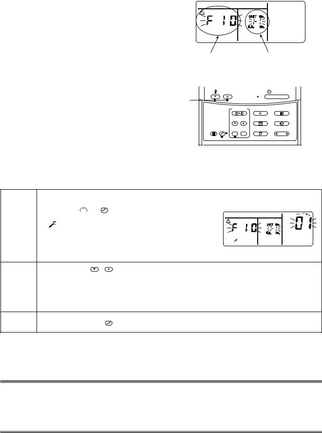
Confirmation and check
When a trouble occurred in the air conditioner, the check code and the indoor unit No. appear on the display part of the remote controller.
The check code is only displayed during the operation.
If the display disappears, operate the air conditioner according to the following “Confirmation of error history” for confirmation.
Confirmation of error history
When a trouble occurred on the air conditioner, the trouble history can be confirmed with the following procedure. (The trouble history is stored in memory up to 4 troubles.)
The history can be confirmed from both operating status and stop status.
Check code |
Indoor unit No. in which |
|
an error occurred |
TEMP. |
|
|
ON / OFF |
2 |
TIMER SET |
FAN |
MODE |
|
TIME |
SAVE |
VENT |
FILTER |
SET CL |
SWING/FIX |
UNIT LOUVER |
RESET TEST |
3 

 1
1
Procedure |
|
|
|
Description |
||||
|
|
|
|
|
|
|
|
|
|
|
SET |
and |
TEST |
||||
|
When pushing |
buttons at the same time for 4 seconds |
||||||
|
or more, the following display appears. |
|
|
|
||||
1 |
If [ |
Service check] is displayed, the mode enters in the trouble |
|
|
||||
|
|
|
||||||
|
|
|
||||||
history mode. |
|
|
|
|
|
|
||
|
• [01 : Order of trouble history] is displayed in CODE No. window. |
|
|
|||||
|
|
|
|
|
|
|
|
|
•[Check code] is displayed.
•[Indoor unit address in which an error occurred] is displayed in UNIT No.
|
Every pushing of [ |
/ |
] button used to set temperature, the trouble history stored in memory is |
|
displayed in order. |
|
|
2 |
The numbers in CODE No. indicate CODE No. [01] (latest) → [04] (oldest). |
||
|
|
|
|
CAUTION
CL
Do not push  button because all the trouble history of the indoor unit will be deleted.
3 |
After confirmation, push |
TEST button to return to the usual display. |
|
1.Check the troubles according to the above procedure.
2.Ask an authorized dealer or qualified service (maintenance) professional to repair or maintain the air conditioner.
3.More details of the service code are explained in Service Manual.
Check these items.
If any of these problems still remains, stop the operation, turn off the leakage breaker, and then notifies the dealer of the serial number and details of the error. Never repair any part by yourself as it is dangerous.
When  and a combination of
  ,
,  ,
,  ,
,  , or
, or  and a number are displayed on the remote controller, also inform the dealer of the display content.
25

26
3-11. Installation Manual
1 ACCESSORY PARTS
n Accessory parts
2 PRECAUTIONS FOR SAFETY
•Ensure that all Local, National and International regulations are satisfied.
•Read this “PRECAUTIONS FOR SAFETY” carefully before Installation.
•The precautions described below include the important items regarding safety. Observe them without fail.
•After the installation work, perform a trial operation (test run) to check for any problem. Follow the Owner’s Manual to explain how to use and maintain the unit to the customer.
Part name |
Q’ty |
Shape |
• |
Turn off the main power supply switch (or breaker) before the unit maintenance. |
|
|
|
• |
Ask the customer to keep the Installation Manual together with the Owner’s Manual. |
Installation plate |
1 |
|
|
WARNING |
|
|
|
|
|
Wireless remote controller |
1 |
|
• Ask an authorized dealer or qualified installation professional to install (including moving)/maintain |
|
|
|
the air conditioner. |
||
|
|
|
|
Inappropriate installation may result in water leakage, electric shock or fire. |
Battery |
2 |
|
• Be sure to connect earth wire. (grounding work) |
|
|
|
Incomplete grounding cause an electric shock. |
||
|
|
|
|
|
|
|
|
|
Do not connect ground wires to gas pipes, water pipes, lightning rods or ground wires for telephone wires. |
Remote controller holder |
1 |
|
• Turn off the main power supply switch or breaker before attempting any electrical work. |
|
|
|
Make sure all power switches are off. Failure to do so may cause electric shock. |
||
|
|
|
|
|
|
|
|
• Install the refrigerant pipe securely during the installation work before operating the air conditioner. |
|
Mounting screw Ø4 × 25L |
6 |
|
|
If the air conditioner is operated with the valve open and without the refrigerant pipe, the compressor sucks air and |
|
|
|
|
the refrigeration cycle is overpressurized, which may cause a burst or injury. |
|
|
|
• When moving the air conditioner for the installation into another place, be very careful not to enter |
|
Pan head wood screw Ø3.1 × 16L |
2 |
|
|
any gaseous matter other than the specified refrigerant into the refrigeration cycle. |
|
|
If air or any other gas is mixed in the refrigerant, the gas pressure in the refrigeration cycle becomes abnormally |
||
|
|
|
|
|
|
|
|
|
high and it resultingly causes pipe burst and injuries on persons. |
Screw Ø4 × 10L |
2 |
|
• Perform installation work properly according to the Installation Manual. |
|
|
|
|
|
Inappropriate installation may result in water leakage, electric shock or fire. |
|
|
|
• When the air conditioner is installed in a small room, provide appropriate measures to ensure that the |
|
Heat insulator |
1 |
|
|
concentration of refrigerant leakage occur in the room does not exceed the critical level. |
|
|
|
• Install the air conditioner securely in a location where the base can sustain the weight adequately. |
|
|
|
|
• Perform the specified installation work to guard against an earthquake. |
|
|
|
|
|
If the air conditioner is not installed appropriately, accidents may occur due to the falling unit. |
<Others>
Name
Owner’s manual
Installation manual
•If refrigerant gas has leaked during the installation work, ventilate the room immediately.
If the leaked refrigerant gas comes in contact with fire, noxious gas may generate.
•After the installation work, confirm that refrigerant gas does not leak.
If refrigerant gas leaks into the room and flows near a fire source, such as a cooking range, noxious gas might generate.
•Electrical work must be performed by a qualified electrician in accordance with the Installation Manual. Make sure the air conditioner uses an exclusive power supply.
An insufficient power supply capacity or inappropriate installation may cause fire.
•Use the specified wires for wiring connect the terminals securely fix.
To prevent external forces applied to the terminals from affecting the terminals.
•Conform to the regulations of the local electric company when wiring the power supply.
Inappropriate grounding may cause electric shock.
•For the refrigerant recovery work (collection of refrigerant from the pipe to the compressor), stop the compressor before disconnecting the refrigerant pipe.
If the refrigerant pipe is disconnected while the compressor is working with the valve open, the compressor sucks air and the refrigeration cycle is overpressurized, which may cause a burst or injury.
27
2 PRECAUTIONS FOR SAFETY
CAUTION
New Refrigerant Air Conditioner Installation
•THIS AIR CONDITIONER ADOPTS THE NEW HFC REFRIGERANT (R410A) WHICH DOES NOT DESTROY OZONE LAYER.
•The characteristics of R410A refrigerant are ; easy to absorb water, oxidizing membrane or oil, and its pressure is approx. 1.6 times higher than that of refrigerant R22. Accompanied with the new refrigerant, refrigerating oil has also been changed. Therefore, during installation work, be sure that water, dust, former refrigerant, or refrigerating oil does not enter the refrigerating cycle.
•To prevent charging an incorrect refrigerant and refrigerating oil, the sizes of connecting sections of charging port of the main unit and installation tools are changed from those for the conventional refrigerant.
•Accordingly the exclusive tools are required for the new refrigerant (R410A).
•For connecting pipes, use new and clean piping designed for R410A, and please care so that water or dust does not enter.
To Disconnect the Appliance from Main Power Supply.
•This appliance must be connected to the main power supply by means of a switch with a contact separation of at least 3 mm.
•The installation fuse must be used for the power supply line of this conditioner.
•Tighten the flare nut with a torque wrench in the specified manner.
Excessive tightening of the flare nut may cause a crack in the flare nut after a long period, which may result in refrigerant leakage.
•Wear heavy gloves and a long sleeve shirt during the installation work to avoid injury.
3 SELECTION OF INSTALLATION PLACE
 WARNING
•Install the air conditioner at enough strong place to withstand the weight of the unit.
If the strength is not enough, the unit may fall down resulting in injury.
CAUTION
•Do not install the air conditioner in a location subject to a risk of exposure to a combustible gas.
If a combustible gas leaks and stays around the unit, a fire may occur.
Upon approval of the customer, install the air conditioner in a place that satisfies the following conditions.
•Place where the unit can be installed horizontally.
•Place where a sufficient servicing space can be ensured for safety maintenance and check.
•Place where drained water will not cause any problem.
Avoid installing in the following places.
•Place exposed to air with high salt content (seaside area), or place exposed to large quantities of sulfide gas (hot spring). (Should the unit be used in these places, special protective measures are needed.)
•A restaurant kitchen where a lot of oil is used or place near machines in a factory
(Oil adhering to the heat exchanger and resin part (cross flow fan) in the indoor unit may reduce the performance, generate mist or dew drop, or deform or damage resin parts.)
•Place where organic solvent is used nearby.
•Place close to a machine generating high frequency.
•Place where the discharged air blows directly into the window of the neighbor house. (Outdoor unit)
•Place where noise of the outdoor unit is easily transmitted.
(When install the outdoor unit on the boundary with the neighbor, pay due attention to the level of noise.)
•Place with poor ventilation.
•Do not use the air conditioner for special purposes such as preserving food, precision instruments, or art objects, or where breeding animals or growing plants are kept.
(This may degrade the quality of preserved materials.)
•Place where any of high-frequency appliances (including inverter devices, private power generators, medical equipment, and communication equipment) and inverter-type fluorescent light is installed.
(A malfunction of the air conditioner, abnormal control, or problems due to noise to such appliances/ equipment may occur.)
•When the wireless remote controller is used in a room equipped with an inverter-type fluorescent light or at a place exposed to direct sunlight, signals from the remote controller may not be received correctly.
•Place where organic solvent is used.
•Place near a door or window exposed to humid outside air (Dew droping may form.).
•Place where special spray is used frequently.

28
3 SELECTION OF INSTALLATION PLACE
n Installation diagram of Indoor and outdoor units
Before installing the |
|
|
|
|
|
|
wireless remote controller |
|
|
|
|
|
|
1. |
Remove the battery cover. |
|
|
|
more |
|
2. |
Insert 2 new batteries |
|
2 |
1 |
or |
Hook |
|
(R03 [AAA] type) following |
|
110mm |
|
||
|
850mm |
|
||||
|
the (+) and (–) positions. |
|
|
|||
|
|
or |
Installation plate |
|||
|
|
|
m |
|||
|
Wireless remote controller |
|
|
ore |
|
|
|
|
|
|
|
|
|
Cover
Hook |
170m |
m |
|
||
|
|
|
|
|
or m |
|
|
ore |
Batteries |
|
|
(Attach |
|
|
|
Air |
filter |
|
|
|
|
|
|
||
to |
the |
|
|
|
Shield pipe |
|
|
|
|
|
|||
|
|
front |
|
|
||
|
|
|
panel |
|
||
|
|
|
|
|
||
Batteries |
|
|
|
|
.) |
Heat |
|
|
|
|
|
insulator |
|
For the rear left and left piping
Wall
Insert the cushion between the indoor unit and wall, and tilt the indoor unit for better operation.
Do not allow the drain hose to get slack.
Cut the piping hole sloped slightly.
Make sure to run the drain hose sloped downward.
The auxiliary piping can be connected to the left, rear left, rear right, right, bottom right or bottom left.
|
|
Right |
|
|
|
Pan head wood screw |
Rear right |
|
|
|
Bottom right |
Left |
||
Wireless remote controller |
Remote controller holder |
|||
Rear left |
Bottom left |
|||
|
|
n Installation space
The indoor unit shall be installed so that its top surface comes at a height of 2m or more. Also it must be avoided to put anything on top of the indoor unit.
1 Reserve space required to install the indoor unit and for service work.
Keep 110mm or more for clearance between top plate of the indoor unit and the ceiling surface.
2 Provide a space as shown for service clearance for the cross flow fan.
nInstallation place
•A place which provides the spaces around the indoor unit as shown in the above diagram.
•A place where there is no obstacle near the air inlet and outlet.
•A place that allows easy installation of the piping to the outdoor unit.
•A place which allows the front panel to be opened.
CAUTION
nWireless remote controller
•A place where there are no obstacles such as a curtain that may block the signal from the indoor unit.
•Do not install the remote controller in a place exposed to direct sunlight or close to a heating source, such as a stove.
•Keep the remote controller at least 1m apart from the nearest TV set or stereo equipment.
(This is necessary to prevent image disturbances or noise interference.)
•The location of the remote controller should be determined as shown below.
Indoor unit
(Side view) |
(Top view) |
|
|
7 m |
Indoor unit |
5 |
m |
|
|||
|
|
45˚
75˚
Reception range
Reception range
Remote controller
: Axial distance
5 m
45˚ |
m |
|
7 |
|
|
Remote controller
4 INSTALLATION OF INDOOR UNIT
 WARNING
Install the air conditioner certainly to sufficiently withstand the weight.
If the strength is insufficient, the unit may fall down resulting in human injury.
Perform a specified installation work to guard against strong wind or earthquake.
An incomplete installation can cause accidents by the units falling and dropping.
REQUIREMENT
Strictly comply with the following rules to prevent damage of the indoor units and human injury.
•Do not put a heavy article on the indoor unit. (Even units are packaged)
•Carry in the indoor unit as it is packaged if possible. If carrying in the indoor unit unpacked by necessity, be sure to use buffering cloth, etc. to not damage the unit.
•To move the indoor unit, do not apply force to the refrigerant pipe, drain pan, foamed parts, or resin parts, etc.
•Carry the package by two or more persons, and do not bundle it with plastic band at positions other than specified.
Be careful to the following items when installing the unit.
• Considering air discharge direction, select an |
OK |
NO GOOD |
||
installation place where discharge air can circulate |
||||
evenly in a room. |
|
|
Bad installation place |
|
Avoid to install the unit at place with “NO GOOD” |
Good installation place |
|
: Not cooled well. |
|
|
|
|||
mark in the right figure. |
Cooled well all over. |
|
|
|
• Direct sunlight to the indoor unit’ s wireless receiver should be avoided. |
Screen |
|
•The microprocessor in the indoor unit should not be too close to RF noise sources. (For details, see the owner’ s manual.)
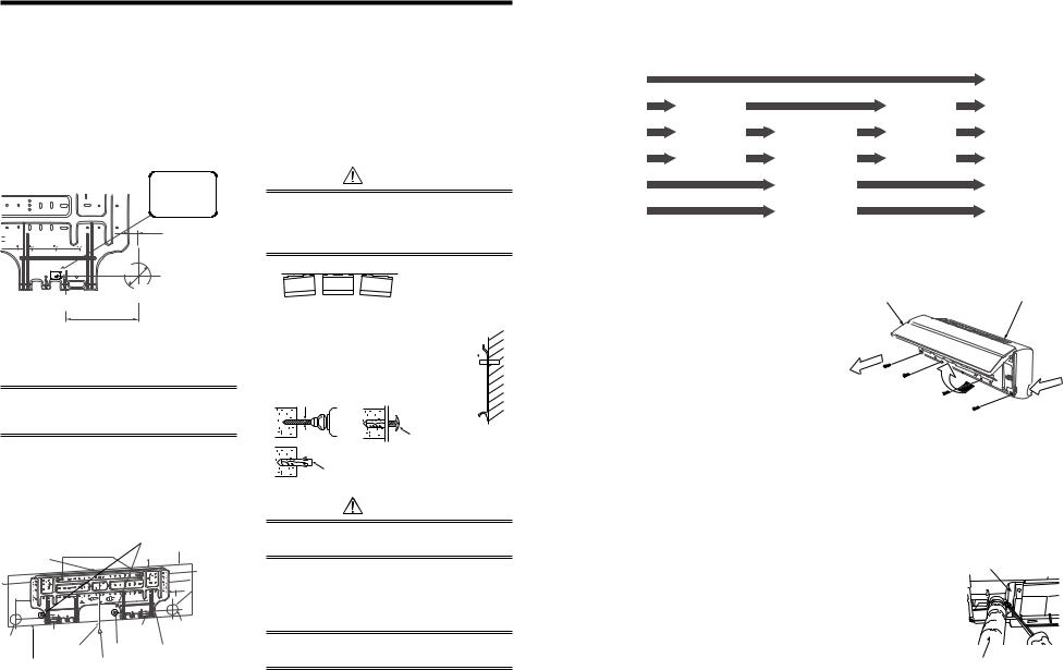
29
5 CUTTING A HOLE AND MOUNTING INSTALLATION PLATE
n Cutting a hole
In case of installing the refrigerant pipes from the rear:
1.Decide the hole position for piping at
180mm from the arrow mark (ð) on the installation plate and drill a hole at a slight downward slant toward outdoor side.
Pipe hole; dia.65mm: AP007-AP018 type Pipe hole; dia.80mm: AP024 type
nWhen the installation plate is directly mounted on the wall
1.Securely fit the installation plate onto the wall by screwing it in the upper and lower parts to hook up the indoor unit.
2.To mount the installation plate on a concrete wall with anchor bolts, utilize the anchor bolt holes as illustrated in the above figure.
3.Install the installation plate horizontally in the wall.
80
65
The center of the pipe hole is above the arrow
80 
65 
1111012101
23 mm
Pipe hole
dia. 65mm: AP007-AP018 type dia. 80mm: AP024 type
180 mm
NOTE
•When drilling a wall that contains a metal lath, wire lath or metal plate, be sure to use a pipe hole brim ring sold separately.
n Mounting the installation plate
Be sure that the installation plate is fix to the wall with screws to make the indoor unit fit to the wall.
|
Anchor bolt holes |
40 |
|
floorfrom |
|
|
Hook |
50 |
|
||
|
|
|
170 |
|
|
170 |
|
|
132 |
|
more |
|
|
|
|
||
|
|
|
23 |
m |
|
|
|
|
|
|
|
85 |
|
|
.65m |
or |
|
|
|
|
dia |
|
|
|
|
|
|
|
2m |
|
|
Hook |
Pipe hole |
|
|
|
Hook |
(dia. 65mm dia. 80mm) |
|||
Pipe hole |
|
||||
Mounting screw |
|
|
|
||
|
|
|
|
||
|
|
|
|
|
|
|
Thread |
Installation plate |
|
||
Indoor unit |
Weight |
|
|
|
|
CAUTION
When installing the installation plate with a mounting screw, do not use the anchor bolt hole.
Otherwise the unit may fall down and result in personal injury and property damage.
NO OK NO
GOOD GOOD
Anchor bolt 
Projection  15mm or less
5mm dia. hole
Mounting screw 4 × 25L
Clip anchor (local parts)
CAUTION
Failure to firmly install the unit may result in personal injury and property damage if the unit falls.
•In case of block, brick, concrete or similar type walls, make 5mm dia. holes in the wall.
•Insert clip anchors for appropriate mounting screws.
NOTE
•Secure four corners and lower parts of the installation plate with 6 mounting screws to install it.
6 PIPING AND DRAIN HOSE INSTALLATION
n Piping and drain hose forming
Apply heat-insulation for both refrigerant pipe and drain hose surely so that no dewing generates inside of the equipment. (Use polyethylene foam for insulating material.)
Rear right |
|
|
|
|
|
|
|
|
|
|
|
|
|
|
|
|
|
|
|
|
|
|
|
|
|
|
Rear left |
|
|
|
|
|
|
|
|
|
|
Removing |
|
|
|
Changing |
|
|
|
|
|
|
|
|
|
||
Bottom left |
|
|
|
|
|
|
||
|
front panel |
|
|
|
drain hose |
|
Piping |
|
|
|
|
|
|
|
|||
|
|
|
|
|
|
|||
|
|
|
|
|
|
|
|
preparation |
Left |
|
|
|
Die-cutting |
|
|
|
|
|
|
|
|
|
|
|
|
|
|
|
|
|
|
|
|||
|
|
|
|
front panel slit |
|
|
|
|
Bottom right |
|
|
|
|
|
|
|
|
|
|
|
|
|
|
|
|
|
|
|
|
|
|
|
|
|
|
|
|
|
|
|
|
|
|
|
Right |
|
|
|
|
|
|
|
|
|
|
|
|
|
|
|
|
|
1. Remove the front panel
The front panel must be removed for piping connections in the left, bottom left, and rear left directions.
•Open the air inlet grille upward.
•Remove the four screws securing the front panel.
•Slightly open the lower part of the front panel,
and then pull the upper part of the front panel toward you to remove it from the rear plate.
Front panel |
Air inlet grille |
2 |
1 |
|
 3
3
2. Die-cutting front panel slit
Cut out the slit on the leftward or right side of the front panel for the left or right connection and the slit on the bottom left or right side of the front panel for the bottom left or right connection with a pair of nippers.
3. Changing drain hose
For leftward connection, bottom-leftward connection and rear leftward connection’s piping, it is necessary to change the drain hose and drain cap.
Without changing the drain hose position, the indoor unit will not fit to the wall.
How to remove the drain hose |
Heat insulator |
|
• The drain hose can be removed by removing the screw securing the drain hose and then pulling out the drain hose.
• When removing the drain hose, be careful of any sharp edges of steel plate. The edges can injuries.
• To install the drain hose, insert the drain hose firmly until
the connection part contacts with heat insulator, and
the secure it with original screw.
Drain hose
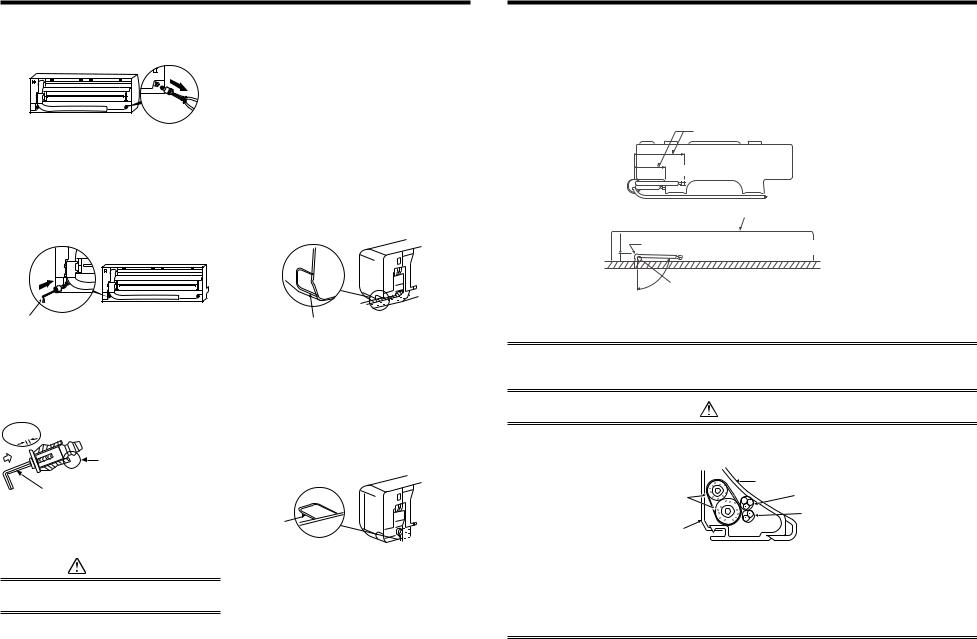
6 PIPING AND DRAIN HOSE INSTALLATION
How to remove the drains cap
Clip the drain cap by needle-nose pliers and pull out.
How to fix the drains cap
1)Insert hexagonal wrench (dia. 4mm) in a center head.
How to remove the drain hose
1)Remove the front panel.
2)Remove the screws of drain hose.
3)Pull out the drain hose.
How to fix the drain hose
1)Put the drain hose.
2)Screw the drain hose to the indoor unit.
3)Install the front panel.
uIn case of right or left piping
•After scribing slits of the front panel with a knife or a marking-off pin, cut them with a pair of nippers oran equivalent tool.
30
4mm
2) Firmly insert drains cap.
No gap
Do not apply lubricating oil (refrigerant machine oil)
when inserting the drain cap.
Application causes deterioration and drain leakage from the plug.
Insert a hexagon wrench (4mm)
CAUTION
Firmly insert the drain hose and drain cap; otherwise, water may leak.
Slit
uIn case of bottom right or bottom left piping
•After scribing slits of the front panel with a knife or a marking-off pin, cut them with a pair of nippers oran equivalent tool.
Slit
uLeft-hand connection with piping
Bend the connecting pipe so that it is laid within 43mm above the wall surface. If the connecting pipe is laid exceeding 43mm above the wall surface, the indoor unit may unstably be set on the wall.
When bending the connecting pipe, make sure to use a spring bender so as not to crush the pipe.
Bend the connection pipe within a radius of 30 mm.
To connect the pipe after installation of the unit (figure)
(To the fore front of flare)
|
520mm |
|
Gas side |
|
|
|
|
|
420mm Liquid side |
||
|
|
|
Outward form of indoor unit |
43mm |
R 30 mm |
|
|
(Use polish polyethylene core or the like for bending pipe.) |
|||
|
80 |
Use the handle of screwdriver, etc. |
|
|
|
||
NOTE
If the pipe is bent incorrectly, the indoor unit may unstably be set on the wall.
After passing the connecting pipe through the pipe hole, connect the connecting pipe to the auxiliary pipes and wrap the facing tape around them.
CAUTION
•Bind the auxiliary pipes (two) and power supply wiring and control wiring with facing tape tightly.
In case of leftward piping and rearleftward piping, bind the auxiliary pipes (two) only with facing tape.
|
Indoor unit |
Auxiliary pipes |
Power supply wiring |
|
Control wiring |
Installation plate |
|
•Carefully arrange pipes so that any pipe does not stick out of the rear plate of the indoor unit.
•Carefully connect the auxiliary pipes and connecting pipes to one another and cut off the insulating tape wound on the connecting pipe to avoid double-taping at the joint, moreover, seal the joint with the vinyl tape, etc.
•Since dewing results in a machine trouble, make sure to insulate both the connecting pipes. (Use polyethylene foam as insulating material.)
•When bending a pipe, carefully do it, not to crush it.
 Loading...