


FILE NO. 400-200603GR
SERVICE MANUAL
Series
DIGITAL AUDIO PLAYER
MES60V, MES30V
(US/CA)
The above models are classified as green products (*1).
This Service Manual describes replacement parts for the green products. When repairing these green product(s), use the part(s) described in this manual and lead-free solder (*2).
For (*1) and (*2), see the next page.
Jun., 2006

(*1) GREEN PRODUCT PROCUREMENT
The EC is actively promoting the WEEE & RoHS Directives that define standards for recycling and reuse of Waste Electrical and Electronic Equipment and for the Restriction of the use of certain Hazardous Substances. From July 1, 2006, the RoHS Directive will prohibit any marketing of new products containing lead.
Increasing attention is given to issues related to the global environmental.Toshiba Corporation recognizes environmental protection as a key management tasks, and is doing its utmost to enhance and improve the quality and scope of its environmental activities. In line with this, Toshiba proactively promotes Green Procurement, and seeks to purchase and use products, parts and materials that have low environmental impacts.
Green procurement of parts is not only confined to manufacture.The same green parts used in manufacture must also be used as replacement parts.
(*2) |
LEAD-FREE SOLDER |
This product is manufactured using lead-free solder as a part of a movement within the CE industry at large to be environmentally responsible. Lead-free solder must be used in the servicing and repair of this product.
WARNING
This product is manufactured using lead free solder.
DO NOT USE LEAD BASED SOLDER TO REPAIR THIS PRODUCT !
The melting temperature of lead-free solder is higher than that of leaded solder by 86°F to 104°F (30°C to 40°C). Use of a soldering iron designed for lead-based solders to repair product made with lead-free solder may result in damage to the component and or PCB being soldered. Great care should be made to ensure high-quality soldering when servicing this product –especially when soldering large components, through-hole pins, and on PCBs – as the level of heat required to melt lead-free solder is high.
Precautions
Safety Precautions for Service
This section provides critical information for safety. Be sure to observe the content.
Meaning of each indication is as follows:
Safety indications mean that death or serious injury may be caused to service personnel DANGER and/or surrounding people or users due to incorrect work by neglecting safety instruc-
tions or due to resulting defects of the product, which indicates imminence of danger.
Death or serious injury may be caused to service personnel and/or surrounding people WARNING or users due to incorrect work by neglecting the following instructions or due to
resulting defects of the product.
Injury or physical damage* may be caused to service personnel and/or surrounding CAUTION people or users due to incorrect work by neglecting the following instructions or due to
resulting defects of the product.
* Physical damage includes damage to buildings, household goods, properties, livestock, and pets.
 WARNING
•Unplug the power cable before starting work (for example, disassembly) that does not need power supply.
Otherwise, it may cause electric shock.
•Use an insulation transformer and/or wear protective gloves when power is ON, and unplug the power cable when replacing parts to avoid electric shock.
•Use specified spare parts of the product for replacement.
Since some parts have safety characteristics (fire resistance, withstand voltage, etc.), use replacement parts with same characteristics.
For safety-sensitive parts specified by marking in circuit diagrams or parts lists, use specified parts.
•After repair work is completed, properly reassemble disassembled parts and securely reconnect cables as they were.
For safety reasons, some insulating materials such as tubes and tapes are used, and some parts are mounted with a gap from the board surface. Furthermore, internal wiring is kept away from heating parts or highvoltage parts by using clampers or by other means. When reassembling/reconnecting these parts, put them as they were.
Do not catch the internal cables by the cabinet or cover. Improper assembling or cable connection may cause electric leak or fire, which may lead to an accident on the user side.
•After repair work is completed, unplug the power cable, and measure the insulation resistance between the external metal portion and plug blade with a 500V megger. The resistance shall be 1M ohms or more.
If the resistance is lower than 1M ohms, inspect and rectify the product.
•Do not alter the product.
Alteration of the product may cause malfunction or failures, which may lead to an accident such as electric leak or fire on the user side.
•Advise users to keep children away from the on-site work area.
Children in the work area may be injured by tools, disassembled product or parts.

Precautions for Removing the Built-in Battery
|
Do not attempt to drive a nail into the built-in battery, nor strike it with a hammer, step |
|
DANGER |
on it or otherwise subject it to strong impact. The electrodes may shortcircuit, resulting |
|
|
in heat generation, explosion or ignition. |
|
|
|
|
|
Do not connect the electrodes (positive/negative terminals) of the built-in battery using |
|
DANGER |
a wire or other metal object. Also avoid carrying or storing the battery together with a |
|
necklace, hairpin or other object made of metal. The electrodes may short-circuit, |
||
|
||
|
resulting in heat generation, explosion or ignition. |
|
|
|
|
|
Do not heat, disassemble or modify the built-in battery or place it in fire or water. |
|
DANGER |
Doing so may cause an explosion, ignition or heat generation, resulting in fire or |
|
|
serious injury. |
|
|
|
|
DANGER |
Do not place the built-in battery near fire or in the heat of the sun. |
|
Doing so may result in fire, explosion or heat generation. |
||
|
||
|
|
|
DANGER |
Do not bring the built-in battery near heating equipment. Doing so may result in fire, |
|
explosion or heat generation. |
||
|
||
|
|
|
|
Wrap the connector of the built-in battery with insulation tape. |
|
DANGER |
Otherwise, the electrodes may short-circuit, resulting in heat generation, explosion or |
|
|
ignition. |
|
|
|
|
WARNING |
Do not place the built-in battery within the reach of small children. |
|
Doing so may result in injury or accident. |
||
|
||
|
|
|
|
If leaked fluid from the built-in battery should enter your eye, rinse with clean water |
|
WARNING |
and seek immediate medical attention. Neglecting proper cleaning or medical treatment |
|
|
may result in eye injury. |
|
|
|
|
CONTENTS |
|
1. PRODUCT OVERVIEW ........................................................................................................................ |
2 |
|
1.1. PRODUCT OUTLINE .................................................................................................................................... |
2 |
|
1.1.1. |
INTERNAL COMPOSITION................................................................................................................... |
2 |
1.1.2. |
ACCESSORIES..................................................................................................................................... |
3 |
1.1.3. PLACE FOR STORING THE FIRMWARE............................................................................................. |
3 |
|
1.1.4. |
ABOUT CONTENT PROTECTION........................................................................................................ |
3 |
1.1.5. HOW MUSIC/VIDEO IS PLAYED BACK ............................................................................................... |
4 |
|
1.1.6. TRANSFER OF CONTENT FROM THE PC.......................................................................................... |
4 |
|
2. BLOCK DIAGRAM ............................................................................................................................... |
5 |
|
2.1. LOGIC CIRCUIT BLOCK DIAGRAM ............................................................................................................. |
5 |
|
2.2. POWER CIRCUIT BLOCK DIAGRAM........................................................................................................... |
6 |
|
3. CAUTIONS ON REPAIR....................................................................................................................... |
7 |
|
3.1. TELL THE OWNER THAT THE CONTENTS ON THE HDD MAY BE ERASED. .......................................... |
7 |
|
3.2. REMOVE THE AC ADAPTOR AND SET THE BATTERY SWITCH TO OFF................................................. |
7 |
|
3.3. WHEN REPLACING THE HDD..................................................................................................................... |
8 |
|
3.3.1. PROTECT THE HDD FROM IMPACT.................................................................................................... |
8 |
|
3.3.2. |
HOLDING THE HDD.............................................................................................................................. |
8 |
3.3.3. |
PROCESS AT HDD REPLACEMENT.................................................................................................... |
9 |
3.4. WHEN REPLACING THE MAIN BOARD .................................................................................................... |
12 |
|
3.4.1. |
UPDATING THE FIRMWARE. ............................................................................................................. |
12 |
3.5. WHEN REPLACING THE LCD AND LCD BACKLIGHT UNIT .................................................................... |
16 |
|
3.5.1. INCORPORATING THEM INTO THE LCD FRAME ............................................................................ |
16 |
|
4. TROUBLESHOOTING........................................................................................................................ |
17 |
|
4.1. ANTICIPATED DEFECTS............................................................................................................................ |
17 |
|
4.2. DEFECT ANALYSIS PROCEDURE AS A MAINTENANCE SERVICE........................................................ |
18 |
|
4.2.1. THE UNIT WILL NOT TURN ON. ........................................................................................................ |
18 |
|
4.2.2. NO SOUND COMES OUT. .................................................................................................................. |
20 |
|
4.2.3. FM CANNOT BE RECEIVED............................................................................................................... |
20 |
|
4.2.4. THE SOUND IS ODD. ......................................................................................................................... |
21 |
|
4.2.5. THE LCD DISPLAY IS ODD. ............................................................................................................... |
21 |
|
4.2.6. THE BUTTONS OF UNIT DO NOT WORK. ........................................................................................ |
21 |
|
4.2.7. THE REMOTE CONTROLLER DOES NOT WORK. ........................................................................... |
21 |
|
4.2.8. |
THE USB CONNECTION FAILS. ........................................................................................................ |
21 |
4.2.9.THE BATTERY CANNOT BE RECHARGED.
|
(WHEN BATTERY-POWERED, THE UNIT PLAYS BACK ONLY FOR A SHORT TIME.) |
....................22 |
|
4.2.10. HDD IS NOT RECOGNIZED. .............................................................................................................. |
23 |
5. |
PROCEDURE TO CONFIRM THE UNIT’S F/W VERSION................................................................ |
24 |
6. |
DISASSEMBLING/REASSEMBLING PROCEDURES ...................................................................... |
25 |
|
6.1. DISASSEMBLING PROCEDURES............................................................................................................. |
25 |
|
6.2. REASSEMBLING PROCEDURES.............................................................................................................. |
30 |
7. |
EXPLODED VIEW .............................................................................................................................. |
34 |
8. |
PARTS LIST........................................................................................................................................ |
35 |
|
1 |
|
1. Product Overview
[TOSHIBA HDD audio player gigabeat S series] is the portable audio player in which the HDD of 30GB/60GB is built. As the built-in HDD is thick, the MES60 is thicker.
Main differences from the previous model (gigabeat X series) are as follows.
•By adopting the push-type button, the operability is enhanced.
•PMC (Portable Media Center) is adopted.
1.1.Product Outline
1.1.1.Internal Composition
The gigabeat S series consists of the following main components.
• Main board
A part of firmware is stored in the flash ROM on the main board.
• HDD
The HDD is partitioned into two partitions. One is for data and the other is for system. The firmware is stored in the system partition.
Contents such as music data are stored in the data partition.
Data other than music data such as Word files can be stored in the external HDD. (But, files cannot be directly opened.)
•TFT color liquid crystal display
•White LED backlight
•Battery
•Switches
13 pieces PMC compliant push button (7 pieces on the front, 6 pieces at sides)
• Cabinet parts
The HDD is covered with special rubber and held in the air. This keeps it resistant to impact and vibration.
2
1.1.2.Accessories
The product is furnished with main accessories as follows.
•AC adaptor
•Power cord (which varies with destinations.)
•USB cable
•USB conversion cable
•Wired remote controller (Option)
•Headphones
•Software CD-ROM Owner’s Manual
1.1.3.Place for storing the firmware
The firmware is stored in the flash ROM on the main board and on the HDD. The firmware is stored in the system partition on the HDD. Even if a PC is connected, the system partition cannot be seen on the Explorer.
1.1.4.About Content Protection
Using the Windows Media DRM10, the contents are protected.
Using the Windows standard application Windows Media Player 10, transfer (copy) the music data (WMA/MP3/WAV format)/video data (WMV) stored in a PC to the HDD so that the transferred content can be played back. Transferring the data via USB is also possible.
When the content, which is once transferred to a PC by the Explorer, is transferred to other gigabeat S series, unless the content is protected by the Windows Media DRM, the content can be played back. But, when the content protected by the Windows Media DRM is transferred to other gigabeat S series, unless the license of the content to be transferred is acquired, the content cannot be played back.
3
1.1.5.How music/video is played back
This section explains how the unit plays back the content (compressed music data (WMA/MP3, PCM music data (WAV) and video data (WMV)) stored on the HDD.
The CPU reads out the content data (WMA/MP3/WAV/WMV) on the HDD and stores it in the SDRAM. The CPU accesses to the HDD every few minutes (It differs depending on the content’s bit rate.), reads out the data, and accumulates it in the SDRAM. When the HDD is not accessed, the power of HDD is turned off to save the power. However, as the PCM music data contains the large amount, the HDD is always powered.
The CPU restores the compressed music data in the SDRAM and converts it to PCM data.
If the data in the SDRAM is video, the CPU restores it to bit map data. The music data restored to the PCM is sent from the SDRAM to the DAC by the CPU. In case of video data, the CPU sends the bit map data to the LCD.)
The DAC converts the PCM music data to the analog signal, which is then outputted to headphones. The CPU sets the volume control and equalizer levels in the DAC, which controls the volume level and equalizer levels, using their set data.
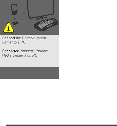
1.1.6.Transfer of content from the PC
When the unit is connected to the PC with the USB cable, the PC recognizes the unit as a MTP device (MultiMedia Transfer Protocol device).
When transferring the content by using the Windows Media Player on the PC, the content data is sent to the unit via USB. Then, according to the MTP protocol, the CPU writes the received content data on the HDD.
4

2. Block diagram
2.1.Logic circuit block diagram
5
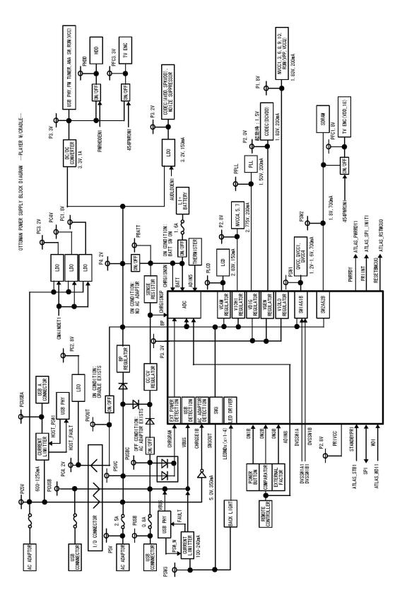
2.2.Power circuit block diagram
6
3. Cautions on repair
Before repairing a product of the gigabeat S series, take the following cautions:
3.1.Tell the owner that the contents on the HDD may be erased.
Replacing or formatting the HDD will erase the content on the HDD.
Therefore, in receiving the product from the owner, ask the owner to back up his/her important data.
3.2.Remove the AC adaptor and set the BATTERY switch to OFF.
Before disassembling, ensure to remove the AC adaptor and set the BATTERY switch to “OFF”.
When the gigabeat S series is powered by the AC adaptor or the battery, even if the power switch is turned off, the power is supplied to the LCD and almost all ICs. Therefore, before repairing, the AC adaptor or the battery must be removed.
By setting the BATTERY switch to “OFF”, the power supply from the battery is stopped and the unit becomes in the same state as when the battery is removed.
7
3.3.When replacing the HDD
3.3.1.Protect the HDD from impact.
Note that the HDD is vulnerable to impact. Merely falling the HDD from a vertical position would give an impact exceeding the specifications.
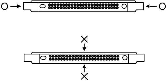
3.3.2.Holding the HDD
When holding the HDD, hold it at the following position:
Do not hold it at the following position:
8
3.3.3.Process at HDD replacement
When replaced to the un-formatted HDD, restore the HDD in the factory setting state by transferring the firmware and the supplied data to the HDD in the procedure below.
[HDD formatting]
1)Set the BATTERY switch to “OFF”.
2)Connect the AC adaptor and start up the unit.
3)Format automatically the HDD and display the menu below on the LCD. Wait until the menu appears.
Fig. Menu of waiting for the PC connection
[T&D Transfer]
4)Start up [Transfer Program (Ottoman.exe) on the PC and select the scenario file (*.ini) in which files to be transferred are described. Ottoman.exe and the scenario file are provided on the CD-ROM (Material No.: 360058245). Names for the destination-wise stored folder and file are different depending on the destination. The relationship between destination and folder is shown on the table below.
Table Destination and Folder
Destination |
Folder name |
Scenario file name |
|
|
|
Japan |
OTTOMAN_T&D_FW_JP |
OTTOMAN_T&D_FW_JP.ini |
U.S.A. |
OTTOMAN_T&D_FW_US |
OTTOMAN_T&D_FW_US.ini |
|
|
|
Start up Ottoman.exe and select the scenario file. Then, the menu below appears.
9
 Loading...