


MMU-AP0122WH
Toshiba MMU-AP0122WH, MMU-AP0122WH-TR, MMU-AP0152WH, MMU-AP0152WH-TR, MMU-AP0182WH Service Manual
...
Leading Innovation
FILE NO. A10-007
SERVICE MANUAL
AIR-CONDITIONER
MULTI TYPE
<2-Way Air Discharge Cassette Type>
MMU-AP0072WH, MMU-AP0072WH-TR
MMU-AP0092WH, MMU-AP0092WH-TR
MMU-AP0122WH, MMU-AP0122WH-TR
MMU-AP0152WH, MMU-AP0152WH-TR
MMU-AP0182WH, MMU-AP0182WH-TR
MMU-AP0242WH, MMU-AP0242WH-TR
MMU-AP0272WH, MMU-AP0272WH-TR
MMU-AP0302WH, MMU-AP0302WH-TR
MMU-AP0362WH, MMU-AP0362WH-TR
MMU-AP0482WH, MMU-AP0482WH-TR
MMU-AP0562WH, MMU-AP0562WH-TR
• This Service Manual describes contents of the 2-Way Air Discharge Cassette indoor unit.
For the outdoor unit, refer to the Manual with FILE No. A10-005, A05-004-1.
PRINTED IN JAPAN, Sep., 2010 ToMo

CONTENTS
Original Instruction............................................................................ 3
Warning Indications on the Air Conditioner Unit ............................5
1. PRECAUTIONS FOR SAFETY .................................................... 6
2. SPECIFICATIONS......................................................................14
3. CONSTRUCTION VIEWS (EXTERNAL VIEWS) ........................ 19
4. WIRING DIAGRAM .................................................................... 24
5. PART RATING ............................................................................ 25
6. REFRIGERATING CYCLE DIAGRAM ....................................... 26
7. CONTROL OUTLINE .................................................................27
8. CONFIGURATION OF CONTROL CIRCUIT.............................. 36
9. APPLIED CONTROL .................................................................44
10. TROUBLESHOOTING ............................................................... 57
11. INSTALLATION MANUAL .......................................................... 86
12. P.C. BOARD EXCHANGE PROCEDURES .............................. 120
13. DETACHMENTS ...................................................................... 125
14. EXPLODED VIEWS AND PARTS LIST.................................... 139

3
Original Instruction
Please read carefully through these instructions that contain important information which complies with the
“Machinery“ Directive (Directive 2006/42/EC), and ensure that you understand them.
Some of the details provided in these instructions differ from the service manual, and the instructions provided
here take precedence.
Generic Denomination: Air Conditioner
Definition of Qualified Installer or Qualified Service Person
The air conditioner must be installed, maintained, repaired and removed by a qualified installer or qualified
service person. When any of these jobs is to be done, ask a qualified installer or qualified service person to do
them for you.
A qualified installer or qualified service person is an agent who has the qualifications and knowledge
described in the table below.
Agent
Qualified
installer
Qualified
service person
Qualifications and knowledge which the agent must have
• The qualified installer is a person who installs, maintains, relocates and removes the air conditioners
made by Toshiba Carrier Corporation. He or she has been trained to install, maintain, relocate and
remove the air conditioners made by Toshiba Carrier Corporation or, alternatively, he or she has
been instructed in such operations by an individual or individuals who have been trained and is thus
thoroughly acquainted with the knowledge related to these operations.
• The qualified installer who is allowed to do the electrical work involved in installation, relocation and
removal has the qualifications pertaining to this electrical work as stipulated by the local laws and
regulations, and he or she is a person who has been trained in matters relating to electrical work on
the air conditioners made by Toshiba Carrier Corporation or, alternatively, he or she has been
instructed in such matters by an individual or individuals who have been trained and is thus
thoroughly acquainted with the knowledge related to this work.
• The qualified installer who is allowed to do the refrigerant handling and piping work involved in
installation, relocation and removal has the qualifications pertaining to this refrigerant handling and
piping work as stipulated by the local laws and regulations, and he or she is a person who has been
trained in matters relating to refrigerant handling and piping work on the air conditioners made by
Toshiba Carrier Corporation or, alternatively, he or she has been instructed in such matters by an
individual or individuals who have been trained and is thus thoroughly acquainted with the
knowledge related to this work.
• The qualified installer who is allowed to work at heights has been trained in matters relating to
working at heights with the air conditioners made by Toshiba Carrier Corporation or, alternatively, he
or she has been instructed in such matters by an individual or individuals who have been trained and
is thus thoroughly acquainted with the knowledge related to this work.
• The qualified service person is a person who installs, repairs, maintains, relocates and removes the
air conditioners made by Toshiba Carrier Corporation. He or she has been trained to install, repair,
maintain, relocate and remove the air conditioners made by Toshiba Carrier Corporation or,
alternatively, he or she has been instructed in such operations by an individual or individuals who
have been trained and is thus thoroughly acquainted with the knowledge related to these operations.
• The qualified service person who is allowed to do the electrical work involved in installation, repair,
relocation and removal has the qualifications pertaining to this electrical work as stipulated by the
local laws and regulations, and he or she is a person who has been trained in matters relating to
electrical work on the air conditioners made by Toshiba Carrier Corporation or, alternatively, he or
she has been instructed in such matters by an individual or individuals who have been trained and is
thus thoroughly acquainted with the knowledge related to this work.
• The qualified service person who is allowed to do the refrigerant handling and piping work involved
in installation, repair, relocation and removal has the qualifications pertaining to this refrigerant
handling and piping work as stipulated by the local laws and regulations, and he or she is a person
who has been trained in matters relating to refrigerant handling and piping work on the air
conditioners made by Toshiba Carrier Corporation or, alternatively, he or she has been instructed in
such matters by an individual or individuals who have been trained and is thus thoroughly
acquainted with the knowledge related to this work.
• The qualified service person who is allowed to work at heights has been trained in matters relating
to working at heights with the air conditioners made by Toshiba Carrier Corporation or, alternatively,
he or she has been instructed in such matters by an individual or individuals who have been trained
and is thus thoroughly acquainted with the knowledge related to this work.

4
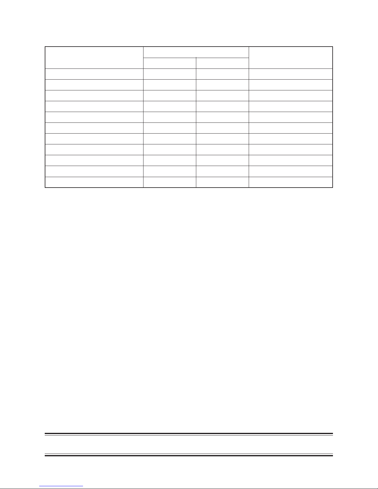
Definition of Protective Gear
When the air conditioner is to be transported, installed, maintained, repaired or removed, wear protective
gloves and ‘safety’ work clothing.
In addition to such normal protective gear, wear the protective gear described below when undertaking the
special work detailed in the table below.
Failure to wear the proper protective gear is dangerous because you will be more susceptible to injury, burns,
electric shocks and other injuries.
Work undertaken
All types of work
Electrical-related work
Work done at heights
(50 cm or more)
Transportation of heavy objects
Repair of outdoor unit
Protective gear worn
Protective gloves
‘Safety’ working clothing
Gloves to provide protection for electricians and from heat
Insulating shoes
Clothing to provide protection from electric shock
Helmets for use in industry
Shoes with additional protective toe cap
Gloves to provide protection for electricians and from heat
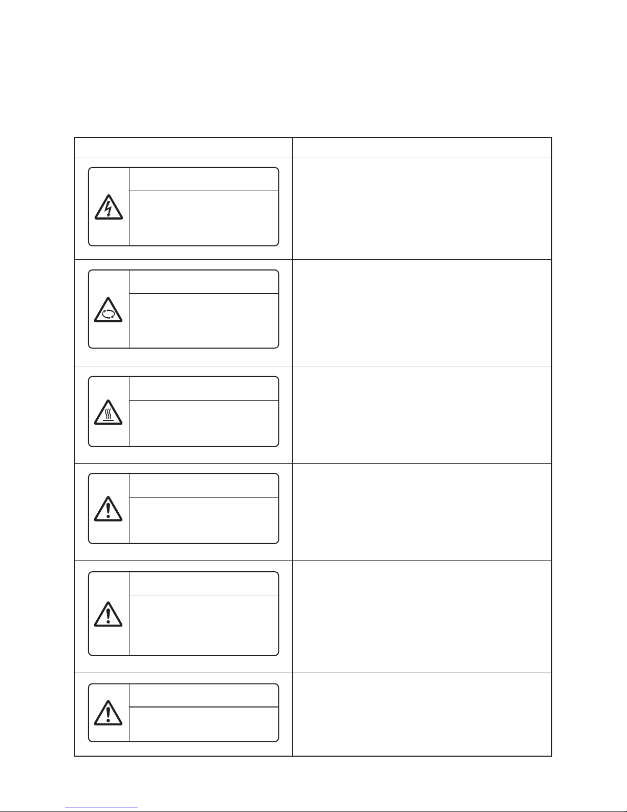
The important contents concerned to the safety are described on the product itself and on this Service Manual.
Please read this Service Manual after understanding the described items thoroughly in the following contents
(Indications/Illustrated marks), and keep them.
[Explanation of indications]
Indication
DANGER
WARNING
CAUTION
Explanation
Indicates contents assumed that an imminent danger causing a death or serious injury of
the repair engineers and the third parties when an incorrect work has been executed.
Indicates possibilities assumed that a danger causing a death or serious injury of the repair
engineers, the third parties, and the users due to troubles of the product after work when an
incorrect work has been executed.
Indicates contents assumed that an injury or property damage (*) may be caused on the
repair engineers, the third parties, and the users due to troubles of the product after work
when an incorrect work has been executed.
∗ Property damage: Enlarged damage concerned to property, furniture, and domestic animal/pet
[Explanation of illustrated marks]
Mark Explanation
Indicates prohibited items (Forbidden items to do)
The sentences near an illustrated mark describe the concrete prohibited contents.
Indicates mandatory items (Compulsory items to do)
The sentences near an illustrated mark describe the concrete mandatory contents.
Indicates cautions (Including danger/warning)
The sentences or illustration near or in an illustrated mark describe the concrete cautious contents.
5
Warning Indications on the Air Conditioner Unit
[Confirmation of warning label on the main unit]
Confirm that labels are indicated on the specified positions.
If removing the label during parts replace, stick it as the original.
Warning indication
WARNING
ELECTRICAL SHOCK HAZARD
Disconnect all remote electric
power supplies before servicing.
WARNING
Moving parts.
Do not operate unit with grille
removed.
Stop the unit before the servicing
CAUTION
High temperature parts.
You might get burned when
removing this panel.
CAUTION
Do not touch the aluminium fins of
the unit.
Doing so may result in injury.
CAUTION
BURST HAZARD
Open the service valves before the
operation, otherwise there might be
the burst.
CAUTION
Do not climb onto the fan guard.
Doing so may result in injury.
Description
WARNING
ELECTRICAL SHOCK HAZARD
Disconnect all remote electric power supplies before servicing.
WARNING
Moving parts.
Do not operate unit with grille removed.
Stop the unit before the servicing.
CAUTION
High temperature parts.
You might get burned when removing this panel.
CAUTION
Do not touch the aluminium fins of the unit.
Doing so may result in injury.
CAUTION
BURST HAZARD
Open the service valves before the operation, otherwise there
might be the burst.
CAUTION
Do not climb onto the fan guard.
Doing so may result in injury.

6
1. PRECAUTIONS FOR SAFETY
WARNING
General
Before starting to repair the air conditioner, read carefully through the Service Manual, and repair the air
conditioner by following its instructions.
Only qualified service person (∗1) is allowed to repair the air conditioner.
Repair of the air conditioner by unqualified person may give rise to a fire, electric shocks, injury, water leaks
and/or other problems.
Only a qualified installer (∗1) or qualified service person (∗1) is allowed to carry out the electrical work of
the air conditioner.
Under no circumstances must this work be done by an unqualified individual since failure to carry out the
work properly may result in electric shocks and/or electrical leaks.
When transporting the air conditioner, wear shoes with protective toe caps, protective gloves and other
protective clothing.
When connecting the electrical wires, repairing the electrical parts or undertaking other electrical jobs, wear
gloves to provide protection for electricians and from heat, insulating shoes and clothing to provide
protection from electric shocks.
Failure to wear this protective gear may result in electric shocks.
Electrical wiring work shall be conducted according to law and regulation in the community and installation
manual. Failure to do so may result in electrocution or shor t circuit.
Only a qualified installer (∗1) or qualified service person (∗1) is allowed to undertake work at heights using
a stand of 50 cm or more or to remove the intake grille of the indoor unit to undertake work.
When working at heights, use a ladder which complies with the ISO 14122 standard, and follow the
procedure in the ladder’s instructions.
Also wear a helmet for use in industry as protective gear to undertake the work.
When working at heights, put a sign in place so that no-one will approach the work location, before
proceeding with the work.
Parts and other objects may fall from above, possibly injuring a person below.
When executing address setting, test run, or troubleshooting through the checking window on the electric
parts box, put on insulated gloves to provide protection from electric shock.
Otherwise you may receive an electric shock.
Do not touch the aluminum fin of the outdoor unit.
You may injure yourself if you do so. If the fin must be touched for some reason, first put on protective
gloves and safety work clothing, and then proceed.
Do not climb onto or place objects on top of the outdoor unit.
You may fall or the objects may fall off of the outdoor unit and result in injury.
When transporting the air conditioner, wear shoes with additional protective toe caps.
When transporting the air conditioner, do not take hold of the bands around the packing carton.
You may injure yourself if the bands should break.
Be sure that a heavy unit (10kg or heavier) such as a compressor is carried by two persons.
This air conditioner has passed the pressure test as specified in IEC 60335-2-40 Annex EE.

7
DANGER
Turn off
breaker.
Electric shock
hazard
Prohibition
Stay on
protection
Before carrying out the installation, maintenance, repair or removal work, be sure to set the circuit breaker
for both the indoor and outdoor units to the OFF position. Otherwise, electric shocks may result.
Before opening the intake grille of the indoor unit or service panel of the outdoor unit, set the circuit breaker
to the OFF position.
Failure to set the circuit breaker to the OFF position may result in electric shocks through contact with the
interior parts.
Only a qualified installer (*1) or qualified service person (*1) is allowed to remove the intake grille of the
indoor unit or service panel of the outdoor unit and do the work required.
Before starting to repair the outdoor unit fan or fan guard, be absolutely sure to set the circuit breaker to the
OFF position, and place a “Work in progress” sign on the circuit breaker.
When cleaning the filter or other parts of the indoor unit, set the circuit breaker to OFF without fail, and
place a “Work in progress” sign near the circuit breaker before proceeding with the work.
When you have noticed that some kind of trouble (such as when an error display has appeared, there is a
smell of burning, abnormal sounds are heard, the air conditioner fails to cool or heat or water is leaking) has
occurred in the air conditioner, do not touch the air conditioner yourself but set the circuit breaker to the
OFF position, and contact a qualified service person.
Take steps to ensure that the power will not be turned on (by marking “out of service” near the circuit
breaker, for instance) until qualified service person arrives.
Continuing to use the air conditioner in the trouble status may cause mechanical problems to escalate or
result in electric shocks or other failure.
When you access inside of the service panel to repair electric parts, wait for about five minutes after turning
off the breaker.
Do not start repairing immediately.Otherwise you may get electric shock by touching terminals of highvoltage capacitors. Natural discharge of the capacitor takes about five minutes.
Place a “Work in progress” sign near the circuit breaker while the installation, maintenance, repair or
removal work is being carried out.
There is a danger of electric shocks if the circuit breaker is set to ON by mistake.
Before operating the air conditioner after having completed the work, check that the electrical parts box
cover of the indoor unit and service panel of the outdoor unit are closed, and set the circuit breaker to the
ON position.
You may receive an electric shock if the power is turned on without first conducting these checks.
If, in the course of carrying out repairs, it becomes absolutely necessary to check out the electrical parts
with the electrical parts box cover of one or more of the indoor units and the service panel of the outdoor
unit removed in order to find out exactly where the trouble lies, wear insulated heat-resistant gloves,
insulated boots and insulated work overalls, and take care to avoid touching any live par ts.
You may receive an electric shock if you fail to heed this warning.
Only qualified service person (∗1) is allowed to do this kind of work.
WARNING
Check earth
wires.
Prohibition of
modification.
Use specified
parts.
Before troubleshooting or repair work, check the earth wire is connected to the earth terminals of the main
unit, otherwise an electric shock is caused when a leak occurs.If the earth wire is not correctly connected,
contact an electric engineer for rework.
After completing the repair or relocation work, check that the ground wires are connected properly.
Be sure to connect earth wire. (Grounding work) Incomplete grounding causes an electric shock.
Do not connect ground wires to gas pipes, water pipes, and lightning rods or ground wires for telephone wires.
Do not modify the products. Do not also disassemble or modify the parts.
It may cause a fire, electric shock or injury.
When any of the electrical parts are to be replaced, ensure that the replacement parts satisfy the
specifications given in the Service Manual (or use the parts contained on the parts list in the Service Manual).
Use of any parts which do not satisfy the required specifications may give rise to electric shocks, smoking
and/or a fire.

8
Do not bring
a child close
to the equipment.
Insulating
measures
No fire
Refrigerant
Assembly/Wiring
Insulator check
Ventilation
If, in the course of carrying out repairs, it becomes absolutely necessary to check out the electrical parts
with the electrical parts box cover of one or more of the indoor units and the service panel of the outdoor
unit removed in order to find out exactly where the trouble lies, put a sign in place so that no-one will
approach the work location before proceeding with the work.
Third-party individuals may enter the work site and receive electric shocks if this warning is not heeded.
Connect the cut-off lead wires with crimp contact, etc., put the closed end side upward and then apply a
water-cut method, otherwise a leak or production of fire is caused at the users’ side.
When performing repairs using a gas burner, replace the refrigerant with nitrogen gas because the oil that
coats the pipes may otherwise burn.
When repairing the refrigerating cycle, take the following measures.
1) Be attentive to fire around the cycle. When using a gas stove, etc., be sure to put out fire before work;
otherwise the oil mixed with refrigerant gas may catch fire.
2) Do not use a welder in the closed room. When using it without ventilation, carbon monoxide poisoning
may be caused.
3) Do not bring inflammables close to the refrigerant cycle, otherwise fire of the welder may catch the
inflammables.
The refrigerant used by this air conditioner is the R410A.
Check the used refrigerant name and use tools and materials of the parts which match with it.
For the products which use R410A refrigerant, the refrigerant name is indicated at a position on the
outdoor unit where is easy to see. To prevent miss-charging, the route of the service port is changed from
one of the former R22.
For an air conditioner which uses R410A, never use other refrigerant than R410A. For an air conditioner
which uses other refrigerant (R22, etc.), never use R410A.
If different types of refrigerant are mixed, abnormal high pressure generates in the refrigerating cycle and
an injury due to breakage may be caused.
When the air conditioner has been installed or relocated, follow the instructions in the Installation Manual and
purge the air completely so that no gases other than the refrigerant will be mixed in the refrigerating cycle.
Failure to purge the air completely may cause the air conditioner to malfunction.
Do not charge refrigerant additionally. If charging refrigerant additionally when refrigerant gas leaks, the
refrigerant composition in the refrigerating cycle changes resulted in change of air conditioner
characteristics or refrigerant over the specified standard amount is charged and an abnormal high
pressure is applied to the inside of the refrigerating cycle resulted in cause of breakage or injury.
Therefore if the refrigerant gas leaks, recover the refrigerant in the air conditioner, execute vacuuming,
and then newly recharge the specified amount of liquid refrigerant.
In this time, never charge the refrigerant over the specified amount.
When recharging the refrigerant in the refrigerating cycle, do not mix the refrigerant or air other than
R410A into the specified refrigerant.
If air or others is mixed with the refrigerant, abnormal high pressure generates in the refrigerating cycle
resulted in cause of injury due to breakage.
After installation work, check the refrigerant gas does not leak.
If the refrigerant gas leaks in the room, poisonous gas generates when gas touches to fire such as fan
heater, stove or cocking stove though the refrigerant gas itself is innocuous.
Never recover the refrigerant into the outdoor unit.
When the equipment is moved or repaired, be sure to recover the refrigerant with recovering device.
The refrigerant cannot be recovered in the outdoor unit; otherwise a serious accident such as breakage or
injury is caused.
After repair work, surely assemble the disassembled parts, and connect and lead the removed wires as before.
Perform the work so that the cabinet or panel does not catch the inner wires.
If incorrect assembly or incorrect wire connection was done, a disaster such as a leak or fire is caused at
user’s side.
After the work has finished, be sure to use an insulation tester set (500V Megger) to check the resistance
is 1MΩ or more between the charge section and the non-charge metal section (Earth position).
If the resistance value is low, a disaster such as a leak or electric shock is caused at user’s side.
When the refrigerant gas leaks during work, execute ventilation.
If the refrigerant gas touches to a fire, poisonous gas generates.
A case of leakage of the refrigerant and the closed room full with gas is dangerous because a shortage of
oxygen occurs. Be sure to execute ventilation.

9
Compulsion
Check after
repair
Do not operate
the unit with
the valve closed.
Check after
reinstallation
Cooling check
When the refrigerant gas leaks, find up the leaked position and repair it surely.
If the leaked position cannot be found up and the repair work is interrupted, pump-down and tighten the
service valve, otherwise the refrigerant gas may leak into the room.
The poisonous gas generates when gas touches to fire such as fan heater, stove or cocking stove though
the refrigerant gas itself is innocuous.
When installing equipment which includes a large amount of charged refrigerant such as a multi air
conditioner in a sub-room, it is necessary that the density does not the limit even if the refrigerant leaks.
If the refrigerant leaks and exceeds the limit density, an accident of shortage of oxygen is caused.
Tighten the flare nut with a torque wrench in the specified manner.
Excessive tighten of the flare nut may cause a crack in the flare nut after a long period, which may result in
refrigerant leakage.
Nitrogen gas must be used for the airtight test.
The charge hose must be connected in such a way that it is not slack.
For the installation/moving/reinstallation work, follow to the Installation Manual.
If an incorrect installation is done, a trouble of the refrigerating cycle, water leak, electric shock or fire is caused.
Once the repair work has been completed, check for refrigerant leaks, and check the insulation resistance
and water drainage. Then perform a trial run to check that the air conditioner is running properly.
After repair work has finished, check there is no trouble.
If check is not executed, a fire, electric shock or injury may be caused.
For a check, turn off the power breaker.
After repair work (installation of front panel and cabinet) has finished, execute a test run to check there is
no generation of smoke or abnormal sound.
If check is not executed, a fire or an electric shock is caused. Before test run, install the front panel and cabinet.
Be sure to fix the screws back which have been removed for installation or other purposes.
Check the following matters before a test run after repairing piping.
• Connect the pipes surely and there is no leak of refrigerant.
• The valve is opened.
Running the compressor under condition that the valve closes causes an abnormal high pressure resulted
in damage of the parts of the compressor and etc. and moreover if there is leak of refrigerant at connecting
section of pipes, the air is sucked and causes further abnormal high pressure resulted in burst or injury.
Only a qualified installer (∗1) or qualified service person (∗1) is allowed to relocate the air conditioner.
It is dangerous for the air conditioner to be relocated by an unqualified individual since a fire, electric
shocks, injury, water leakage, noise and/or vibration may result.
Check the following items after reinstallation.
1) The earth wire is correctly connected.
2) The power cord is not caught in the product.
3) There is no inclination or unsteadiness and the installation is stable.
If check is not executed, a fire, an electric shock or an injury is caused.
When carrying out the pump-down work shut down the compressor before disconnecting the refrigerant pipe.
Disconnecting the refrigerant pipe with the service valve left open and the compressor still operating will
cause air, etc. to be sucked in, raising the pressure inside the refrigeration cycle to an abnormally high
level, and possibly resulting in reputing, injury, etc.
When the service panel of the outdoor unit is to be opened in order for the compressor or the area around
this part to be repaired immediately after the air conditioner has been shut down, set the circuit breaker to
the OFF position, and then wait at least 10 minutes before opening the service panel.
If you fail to heed this warning, you will run the risk of burning yourself because the compressor pipes and
other parts will be very hot to the touch. In addition, before proceeding with the repair work, wear the kind
of insulated heat-resistant gloves designed to protect electricians.
Take care not to get burned by compressor pipes or other parts when checking the cooling cycle while
running the unit as they get heated while running.
Be sure to put on gloves providing protection for electric shock and heat.
When the service panel of the outdoor unit is to be opened in order for the fan motor, reactor, inverter or
the areas around these parts to be repaired immediately after the air conditioner has been shut down, set
the circuit breaker to the OFF position, and then wait at least 10 minutes before opening the service panel.
If you fail to heed this warning, you will run the risk of burning yourself because the fan motor, reactor,
inverter heat sink and other parts will be very hot to the touch.
In addition, before proceeding with the repair work, wear the kind of insulated heat-resistant gloves
designed to protect electricians.

10
Installation
Only a qualified installer (∗1) or qualified service person (∗1) is allowed to install the air conditioner.
If the air conditioner is installed by an unqualified individual, a fire, electric shocks, injury, water leakage,
noise and/or vibration may result.
Before starting to install the air conditioner, read carefully through the Installation Manual, and follow its
instructions to install the air conditioner.
Be sure to use the company-specified products for the separately purchased parts.
Use of non-specified products may result in fire, electric shock, water leakage or other failure.
Have the installation performed by a qualified installer.
Do not supply power from the power terminal block equipped on the outdoor unit to another outdoor unit.
Capacity overflow may occur on the terminal block and may result in fire.
Do not install the air conditioner in a location that may be subject to a risk of expire to a combustible gas.
If a combustible gas leaks and becomes concentrated around the unit, a fire may occur.
Install the indoor unit at least 2.5 m above the floor level since otherwise the users may injure themselves or
receive electric shocks if they poke their fingers or other objects into the indoor unit while the air conditioner
is running.
Install a circuit breaker that meets the specifications in the installation manual and the stipulations in the
local regulations and laws.
Install the circuit breaker where it can be easily accessed by the qualified service person (∗1).
If you install the unit in a small room, take appropriate measures to prevent the refrigerant from exceeding
the limit concentration even if it leaks.
Consult the dealer from whom you purchased the air conditioner when you implement the measures.
Accumulation of highly concentrated refrigerant may cause an oxygen deficiency accident.
Do not place any combustion appliance in a place where it is directly exposed to the wind of air conditioner,
otherwise it may cause imperfect combustion.
Explanations given to user
• If you have discovered that the fan grille is damaged, do not approach the outdoor unit but set the circuit
breaker to the OFF position, and contact a qualified service person to have the repairs done.
Do not set the circuit breaker to the ON position until the repairs are completed.
Relocation
• Only a qualified installer (∗1) or qualified service person (∗1) is allowed to relocate the air conditioner.
It is dangerous for the air conditioner to be relocated by an unqualified individual since a fire, electric shocks,
injury, water leakage, noise and/or vibration may result.
• When carrying out the pump-down work shut down the compressor before disconnecting the refrigerant pipe.
Disconnecting the refrigerant pipe with the service valve left open and the compressor still operating will
cause air, etc. to be sucked in, raising the pressure inside the refrigeration cycle to an abnormally high level,
and possibly resulting in reputing, injury, etc.
(∗1) Refer to the “Definition of Qualified Installer or Qualified Service Person.”
11
SPECIFICATIONS
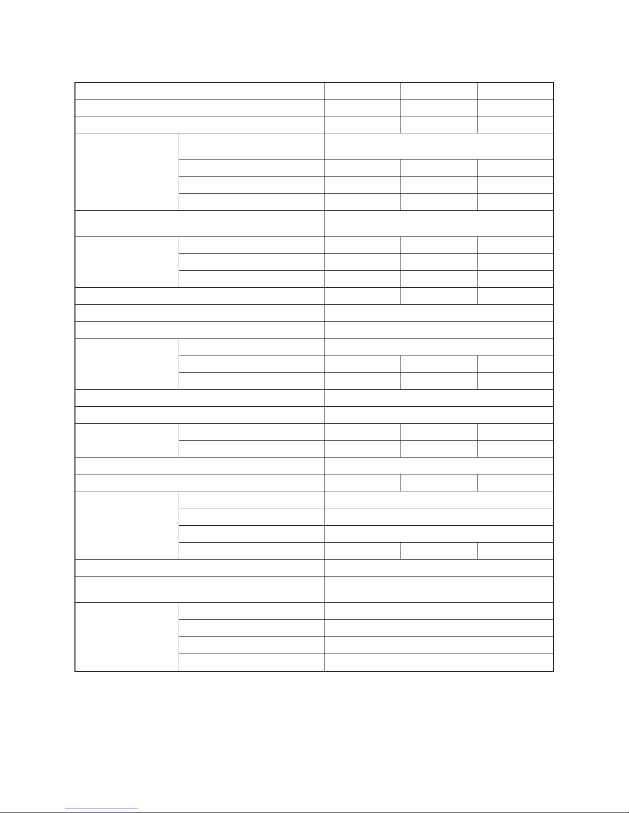
∗
Under 70 dBA
DECLARATION OF CONFORMITY
Manufacturer: Toshiba Carrier Corporation
336 Tadehara, Fuji-shi, Shizuoka-ken 416-8521 JAPAN
Authorized Representative/ Nick Ball
TCF holder: Toshiba EMEA Engineering Director
Toshiba Carrier UK Ltd.
Porsham Close, Belliver Industrial Estate,
PLYMOUTH, Devon, PL6 7DB.
United Kingdom
Hereby declares that the machinery described below:
Generic Denomination: Air Conditioner
Model/type: Indoor unit
MMU-AP0072WH, MMU-AP0092WH, MMU-AP0122WH, MMU-AP0152WH,
MMU-AP0182WH, MMU-AP0242WH, MMU-AP0272WH, MMU-AP0302WH,
MMU-AP0362WH, MMU-AP0482WH, MMU-AP0562WH
MMU-AP0072WH-TR, MMU-AP0092WH-TR, MMU-AP0122WH-TR,
MMU-AP0152WH-TR, MMU-AP0182WH-TR, MMU-AP0242WH-TR,
MMU-AP0272WH-TR, MMU-AP0302WH-TR, MMU-AP0362WH-TR,
MMU-AP0482WH-TR, MMU-AP0562WH-TR
Commercial name: Super Modular Multi System Air Conditioner
Complies with the provisions of the “Machinery” Directive (Directive 2006/42/EC) and
the regulations transposing into national law
Complies with the provisions of the following harmonized standard:
EN 378-2: 2008+A1:2009
NOTE
This declaration becomes invalid if technical or operational modifications are introduced without the
manufacturer’s consent.
Model
MMU-AP0072WH (–TR)
MMU-AP0092WH (–TR)
MMU-AP0122WH (–TR)
MMU-AP0152WH (–TR)
MMU-AP0182WH (–TR)
MMU-AP0242WH (–TR)
MMU-AP0272WH (–TR)
MMU-AP0302WH (–TR)
MMU-AP0362WH (–TR)
MMU-AP0482WH (–TR)
MMU-AP0562WH (–TR)
Sound power level (dBA)
Cooling Heating
∗∗
∗∗
∗∗
∗∗
∗∗
∗∗
∗∗
∗∗
∗∗
∗∗
∗∗
Weight (kg)
19 (10)
19 (10)
19 (10)
19 (10)
26 (14)
26 (14)
26 (14)
26 (14)
36 (14)
36 (14)
36 (14)

12
• New Refrigerant (R410A)
This air conditioner adopts a new HFC type refrigerant (R410A) which does not deplete the ozone layer.
1. Safety Caution Concerned to New Refrigerant
The pressure of R410A is high 1.6 times of that of the former refrigerant (R22).
Accompanied with change of refrigerant, the refrigerating oil has been also changed.
Therefore, be sure that water, dust, the former refrigerant or the former refrigerating oil is not mixed into
the refrigerating cycle of the air conditioner with new refrigerant during installation work or service work.
If an incorrect work or incorrect service is performed, there is a possibility to cause a serious accident.
Use the tools and materials exclusive to R410A to purpose a safe work.
2. Cautions on Installation/Service
(1) Do not mix the other refrigerant or refrigerating oil.
For the tools exclusive to R410A, shapes of all the joints including the service port differ from those
of the former refrigerant in order to prevent mixture of them.
(2) As the use pressure of the new refrigerant is high, use material thickness of the pipe and tools
which are specified for R410A.
(3) In the installation time, use clean pipe materials and work with great attention so that water and
others do not mix in because pipes are affected by impurities such as water, oxide scales, oil, etc.
Use the clean pipes.
Be sure to brazing with flowing nitrogen gas. (Never use gas other than nitrogen gas.)
(4) For the earth protection, use a vacuum pump for air purge.
(5) R410A refrigerant is azeotropic mixture type refrigerant.
Therefore use liquid type to charge the refrigerant. (If using gas for charging, composition of the
refrigerant changes and then characteristics of the air conditioner change.)
3. Pipe Materials
For the refrigerant pipes, copper pipe and joints are mainly used.
It is necessary to select the most appropriate pipes to conform to the standard.
Use clean material in which impurities adhere inside of pipe or joint to a minimum.
(1) Copper pipe
<Piping>
The pipe thickness, flare finishing size, flare nut and others differ according to a refrigerant type.
When using a long copper pipe for R410A, it is recommended to select “Copper or copper-base pipe without
seam” and one with bonded oil amount 40mg/10m or less.
Also do not use crushed, deformed, discolored (especially inside) pipes. (Impurities cause clogging of
expansion valves and capillary tubes.)
<Flare nut>
Use the flare nuts which are attached to the air conditioner unit.
(2) Joint
The flare joint and socket joint are used for joints of the copper pipe.
The joints are rarely used for installation of the air conditioner.
However clear impurities when using them.
13
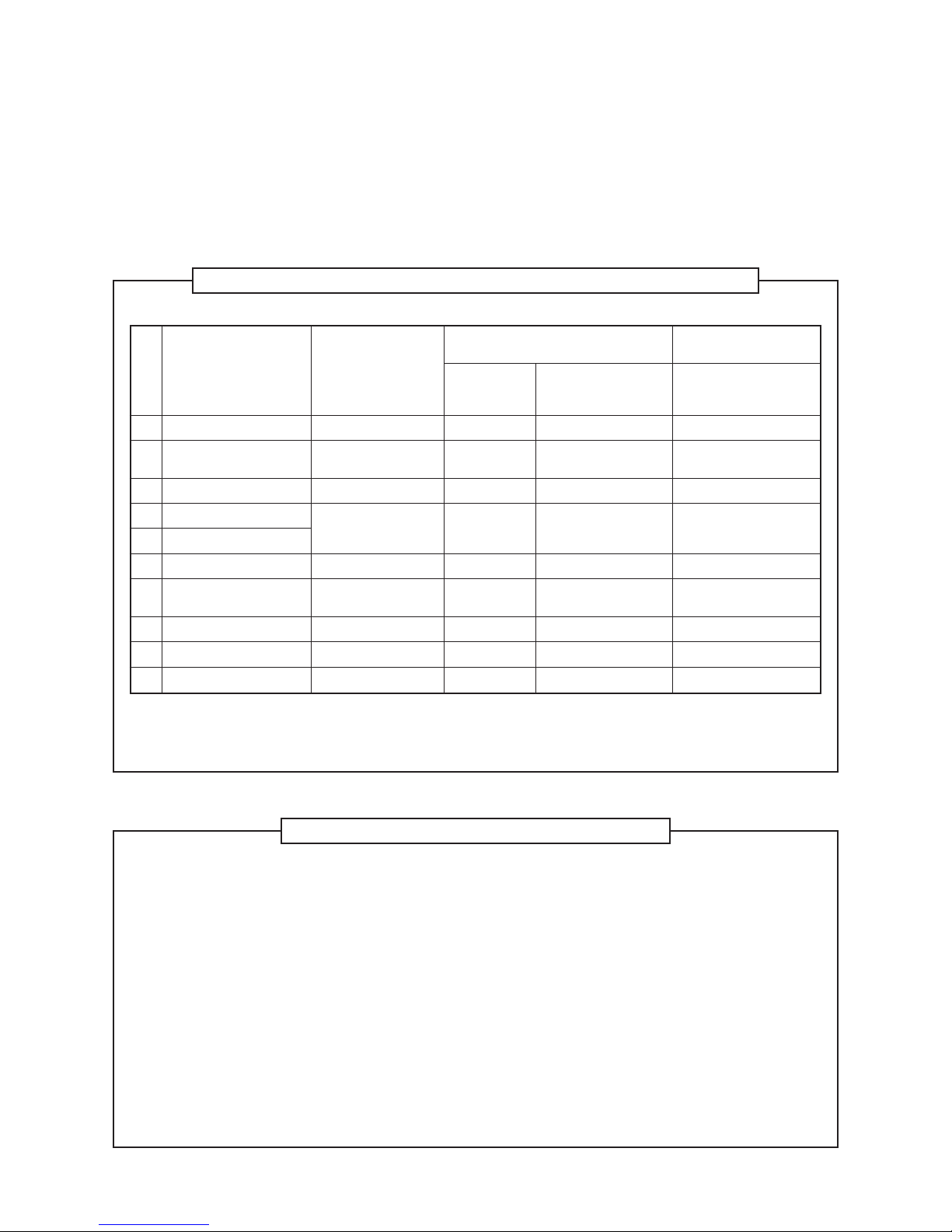
4. Tools
(1) Required Tools for R410A
Mixing of different types of oil may cause a trouble such as generation of sludge, clogging of
capillary, etc. Accordingly, the tools to be used are classified into the following three types.
1) Tools exclusive for R410A (Those which cannot be used for conventional refrigerant (R22))
2) Tools exclusive for R410A, but can be also used for conventional refrigerant (R22)
3) Tools commonly used for R410A and for conventional refrigerant (R22)
The table below shows the tools exclusive for R410A and their interchangeability.
Tools exclusive for R410A (The following tools for R410A are required.)
Tools whose specifications are changed for R410A and their interchangeability
(Note 1) When flaring is carried out for R410A using the conventional flare tools, adjustment of projection
margin is necessary. For this adjustment, a copper pipe gauge, etc. are necessary.
(Note 2) Charging cylinder for R410A is being currently developed.
General tools (Conventional tools can be used.)
In addition to the above exclusive tools, the following equipments which serve also for R22 are necessary
as the general tools.
1) Vacuum pump
Use vacuum pump by attaching vacuum pump adapter.
2) Torque wrench 8) Spanner or Monkey wrench
3) Pipe cutter 9) Hole core drill
4) Reamer 10) Hexagon wrench (Opposite side 4mm)
5) Pipe bender 11) Tape measure
6) Level vial 12) Metal saw
7) Screwdriver (+, –)
Also prepare the following equipments for other installation method and run check.
1) Clamp meter 3) Insulation resistance tester
2) Thermometer 4) Electroscope
No.
Used tool
Flare tool
Copper pipe gauge for
adjusting projection margin
Torque wrench
Gauge manifold
Charge hose
Vacuum pump adapter
Electronic balance for
refrigerant charging
Refrigerant cylinder
Leakage detector
Charging cylinder
Usage
Pipe flaring
Flaring by conventional
flare tool
Connection of flare nut
Evacuating, refrigerant
charge, run check, etc.
Vacuum evacuating
Refrigerant charge
Refrigerant charge
Gas leakage check
Refrigerant charge
R410A
air conditioner installation
Existence of Whether
new equipment conventional equipment
for R410A can be used
Ye s ∗(Note 1)
Ye s ∗(Note 1)
Ye s N o
Ye s N o
Ye s N o
Ye s Ye s
Ye s N o
Ye s N o
(Note 2) No
Conventional air
conditioner installation
Whether new equipment
can be used with
conventional refrigerant
Ye s
∗(Note 1)
No
No
Ye s
Ye s
No
Ye s
No

14
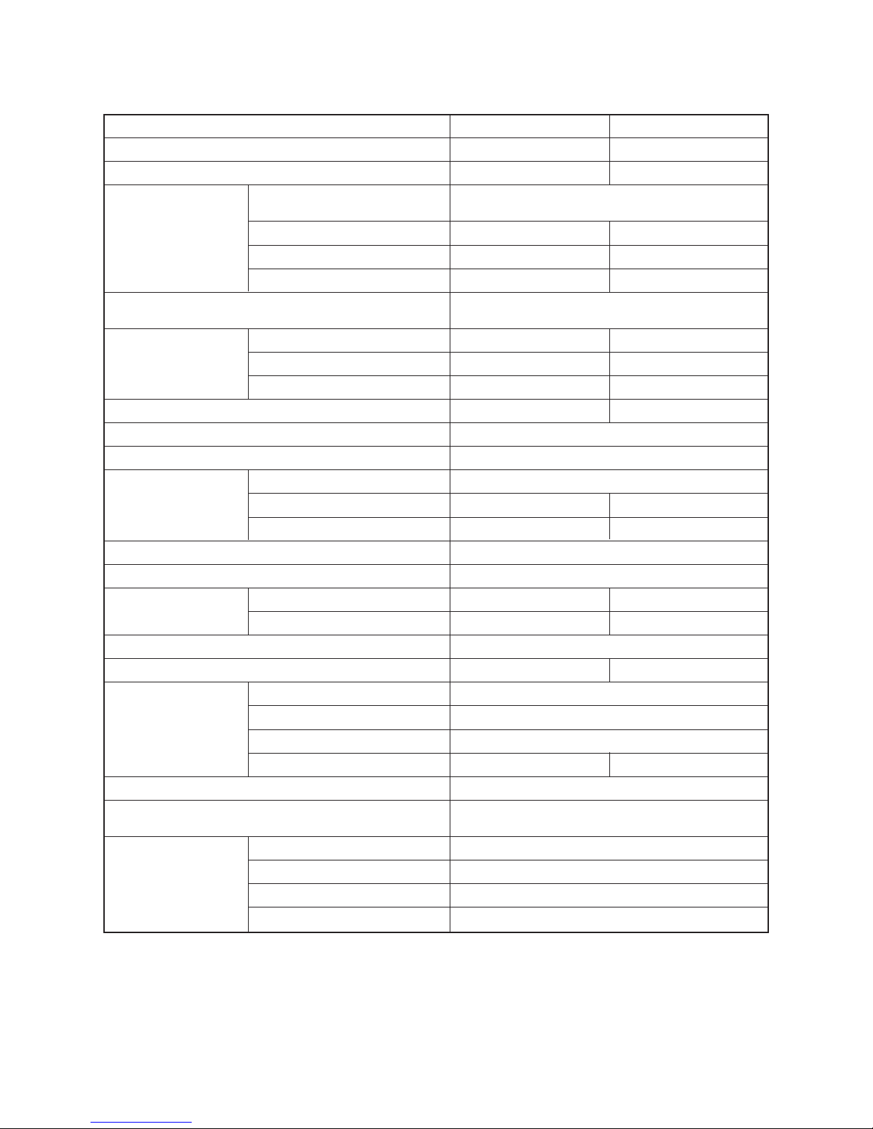
2. SPECIFICATIONS
2-1. Indoor Unit
MMU-AP0072WH, AP0092WH
Model name
Cooling capacity (∗1) kW
Heating capacity (∗1) kW
Electrical
Power supply
Running current A
Power consumption kW
charastaristics
Starting current A
Appearance
Height mm
Outer dimension Width mm
Depth mm
Total weight kg
Heat exchanger
Soundproof/Heat-insulating material
Fan
Fan unit Standard air flow (–M, –L) m³/h
Motor W
Air filter
Controller (∗2)
Connecting pipe
Gas side mm
Liquid side mm
Drain port (Nominal dia. mm)
Sound puressure level High (–Mid., –Low) dB
Model name
Ceiling panel
Appearance (Color)
(∗2)
Outer dimension mm
Total weight kg
Remote controller wiring
Crossover wiring
(Up to 1000 m)
(Up to 2000 m)
Auxiliary fresh air flange
Option parts
Filter chamber
Super long life filter
Wireless remote controller Kit
MMU-AP0072WH MMU-AP0092WH
2.2 2.8
2.5 3.2
1 phase 50 Hz 230 V (220 V-240 V) /1 phase 60 Hz 220 V
(Separate power supply for indoor units is required.)
0.23 / 0.23 0.23 / 0.23
0.029 / 0.029 0.029 / 0.029
0.35 / 0.35 0.35 / 0.35
Heat-insulating material attached
Zinc hot dipping steel plate
295 295
815 815
570 570
19 19
Finned tube
Non-flammable insulation
Turbo fan
558 (– 498 – 450) 558 (– 498 – 450)
20 20
Standard filter (Long life filter)
Remote controller
9.5 9.5
6.4 6.4
25 (Polyvinyl chloride tube)
34–32–30 34–32–30
RBC-UW283PG(W)-E
Moon white (Muncel 2.5GY9.0/0.5)
Height 20 × Width 1050 × Depth 680
10 10
VCTF 0.5 to 2.0 mm² (2 cores)
MVVS (Shield wire) 1.25 mm² × 2 cores
MVVS (Shield wire) 2.00 mm² × 2 cores
TCB-FF151US-E
TCB-FC283UW-E
TCB-LF283UW-E
RBC-AX23UW (W)-E
(∗1) Cooling / heating capacity is based on single connection operation with standard piping length under
Japanese Industrial Standard B 8615 Condition 1.
(∗2) Remote controller and ceiling panel are sold separately.
(50/60 Hz)

15
MMU-AP0122WH, AP0152WH
(50/60 Hz)
MMU-AP0122WH MMU-AP0152WH
3.6 4.5
4.0 5.0
1 phase 50 Hz 230 V (220 V-240 V) /1 phase 60 Hz 220 V
(Separate power supply for indoor units is required.)
0.23 / 0.23 0.24 / 0.24
0.029 / 0.029 0.030 / 0.030
0.35 / 0.35 0.36 / 0.36
Heat-insulating material attached
Zinc hot dipping steel plate
295 295
815 815
570 570
19 19
Finned tube
Non-flammable insulation
Turbo fan
558 (– 498 – 450) 600 (–534 – 450)
20 20
Standard filter (Long life filter)
Remote controller
9.5 12.7
6.4 6.4
25 (Polyvinyl chloride tube)
34–32–30 35–33–30
RBC-UW283PG(W)-E
Moon white (Muncel 2.5GY9.0/0.5)
Height 20 × Width 1050 × Depth 680
10 10
VCTF 0.5 to 2.0 mm² (2 cores)
MVVS (Shield wire) 1.25 mm² × 2 cores
MVVS (Shield wire) 2.00 mm² × 2 cores
TCB-FF151US-E
TCB-FC283UW-E
TCB-LF283UW-E
RBC-AX23UW (W)-E
(∗1) Cooling / heating capacity is based on single connection operation with standard piping length under
Japanese Industrial Standard B 8615 Condition 1.
(∗2) Remote controller and ceiling panel are sold separately.
Model name
Cooling capacity (∗1) kW
Heating capacity (∗1) kW
Electrical
Power supply
Running current A
Power consumption kW
charastaristics
Starting current A
Appearance
Height mm
Outer dimension Width mm
Depth mm
Total weight kg
Heat exchanger
Soundproof/Heat-insulating material
Fan
Fan unit Standard air flow (–M, –L) m³/h
Motor W
Air filter
Controller (∗2)
Connecting pipe
Gas side mm
Liquid side mm
Drain port (Nominal dia. mm)
Sound puressure level High (–Mid., –Low) dB
Model name
Ceiling panel
Appearance (Color)
(∗2)
Outer dimension mm
Total weight kg
Remote controller wiring\
Crossover wiring
(Up to 1000 m)
(Up to 2000 m)
Auxiliary fresh air flange
Option parts
Filter chamber
Super long life filter
Wireless remote controller Kit

16
MMU-AP0182WH, AP0242WH
(50/60 Hz)
(∗1) Cooling / heating capacity is based on single connection operation with standard piping length under
Japanese Industrial Standard B 8615 Condition 1.
(∗2) Remote controller and ceiling panel are sold separately.
Model name
Cooling capacity (∗1) kW
Heating capacity (∗1) kW
Electrical
Power supply
Running current A
Power consumption kW
charastaristics
Starting current A
Appearance
Height mm
Outer dimension Width mm
Depth mm
Total weight kg
Heat exchanger
Soundproof/Heat-insulating material
Fan
Fan unit Standard air flow (–M, –L) m³/h
Motor W
Air filter
Controller (∗2)
Connecting pipe
Gas side mm
Liquid side mm
Drain port (Nominal dia. mm)
Sound puressure level High (–Mid., –Low) dB
Model name
Ceiling panel
Appearance (Color)
(∗2)
Outer dimension mm
Total weight kg
Remote controller wiring
Crossover wiring
(Up to 1000 m)
(Up to 2000 m)
Auxiliary fresh air flange
Option parts
Filter chamber
Super long life filter
Wireless remote controller Kit
MMU-AP0182WH MMU-AP0242WH
5.6 7.1
6.3 8.0
1 phase 50 Hz 230 V (220 V-240 V) /1 phase 60 Hz 220 V
(Separate power supply for indoor units is required.)
0.32 / 0.32 0.39 / 0.39
0.044 / 0.044 0.054 / 0.054
0.48 / 0.48 0.59 / 0.59
Heat-insulating material attached
Zinc hot dipping steel plate
345 345
1180 1180
570 570
26 26
Finned tube
Non-flammable insulation
Centrifugal fan
900 (– 750 – 618) 1050 (– 840 – 738)
30 40
Standard filter (Long life filter)
Remote controller
12.7 15.9
6.4 9.5
25 (Polyvinyl chloride tube)
35–33–30 38–35–33
RBC-UW803PG(W)-E
Moon white (Muncel 2.5GY9.0/0.5)
Height 20 × Width 1415 × Depth 680
14 14
VCTF 0.5 to 2.0 mm² (2 cores)
MVVS (Shield wire) 1.25 mm² × 2 cores
MVVS (Shield wire) 2.00 mm² × 2 cores
TCB-FF151US-E
TCB-FC803UW-E
TCB-LF803UW-E
RBC-AX23UW (W)-E
17
MMU-AP0272WH, AP0302WH
(50/60 Hz)
MMU-AP0272WH MMU-AP0302WH
8.0 9.0
9.0 10.0
1 phase 50 Hz 230 V (220 V-240 V) /1 phase 60 Hz 220 V
(Separate power supply for indoor units is required.)
0.39 / 0.39 0.46 / 0.46
0.054 / 0.054 0.064 / 0.064
0.59 / 0.59 0.69 / 0.69
Heat-insulating material attached
Zinc hot dipping steel plate
345 345
1180 1180
570 570
26 26
Finned tube
Non-flammable insulation
Centrifugal fan
1050 (– 840 – 738) 1260 (– 900 – 780)
40 50
Standard filter (Long life filter)
Remote controller
15.9 15.9
9.5 9.5
25 (Polyvinyl chloride tube)
38–35–33 40–37–34
RBC-UW803PG(W)-E
Moon white (Muncel 2.5GY9.0/0.5)
Height 20 × Width 1415 × Depth 680
14 14
VCTF 0.5 to 2.0 mm² (2 cores)
MVVS (Shield wire) 1.25 mm² × 2 cores
MVVS (Shield wire) 2.00 mm² × 2 cores
TCB-FF151US-E
TCB-FC803UW-E
TCB-LF803UW-E
RBC-AX23UW (W)-E
(∗1) Cooling / heating capacity is based on single connection operation with standard piping length under
Japanese Industrial Standard B 8615 Condition 1.
(∗2) Remote controller and ceiling panel are sold separately.
Model name
Cooling capacity (∗1) kW
Heating capacity (∗1) kW
Electrical
Power supply
Running current A
Power consumption kW
charastaristics
Starting current A
Appearance
Height mm
Outer dimension Width mm
Depth mm
Total weight kg
Heat exchanger
Soundproof/Heat-insulating material
Fan
Fan unit Standard air flow (–M, –L) m³/h
Motor W
Air filter
Controller (∗2)
Connecting pipe
Gas side mm
Liquid side mm
Drain port (Nominal dia. mm)
Sound puressure level High (–Mid., –Low) dB
Model name
Ceiling panel
Appearance (Color)
(∗2)
Outer dimension mm
Total weight kg
Remote controller wiring
Crossover wiring
(Up to 1000 m)
(Up to 2000 m)
Auxiliary fresh air flange
Option parts
Filter chamber
Super long life filter
Wireless remote controller Kit
18
MMU-AP0362WH MMU-AP0482WH MMU-AP0562WH
11.2 14.0 16.0
12.5 16.0 18.0
1 phase 50 Hz 230 V (220 V-240 V) /1 phase 60 Hz 220 V
(Separate power supply for indoor units is required.)
0.48 / 0.48 0.57 / 0.57 0.75 / 0.75
0.073 / 0.073 0.088 / 0.088 0.117 / 0.117
0.72 / 0.72 0.86 / 0.86 1.13 / 1.13
Heat-insulating material attached
Zinc hot dipping steel plate
345 345 345
1600 1600 1600
570 570 570
36 36 36
Finned tube
Non-flammable insulation
Centrifugal fan
1740 (–1434–1182) 1800 (–1482–1230) 2040 (–1578–1320)
70 70 70
Standard filter (Long life filter)
Remote controller
15.9 15.9 15.9
9.5 9.5 9.5
25 (Polyvinyl chloride tube)
42–39–36 43–40–37 46–42–39
RBC-UW1403PG(W)-E
Moon white (Muncel 2.5GY9.0/0.5)
Height 20 × Width 1835 × Depth 680
14 14 14
VCTF 0.5 to 2.0 mm² (2 cores)
MVVS (Shield wire) 1.25 mm² × 2 cores
MVVS (Shield wire) 2.00 mm² × 2 cores
TCB-FF151US-E
TCB-FC1403UW-E
TCB-LF1403UW-E
RBC-AX23UW (W)-E
Model name
Cooling capacity (∗1) kW
Heating capacity (∗1) kW
Electrical
Power supply
Running current A
Power consumption kW
charastaristics
Starting current A
Appearance
Height mm
Outer dimension Width mm
Depth mm
Total weight kg
Heat exchanger
Soundproof/Heat-insulating material
Fan
Fan unit Standard air flow (–M, –L) m³/h
Motor W
Air filter
Controller (∗2)
Connecting pipe
Gas side mm
Liquid side mm
Drain port (Nominal dia. mm)
Sound puressure level High (–Mid., –Low) dB
Model name
Ceiling panel
Appearance (Color)
(∗2)
Outer dimension mm
Total weight kg
Remote controller wiring
Crossover wiring
(Up to 1000 m)
(Up to 2000 m)
Auxiliary fresh air flange
Option parts
Filter chamber
Super long life filter
Wireless remote controller Kit
MMU-AP0362WH, AP0482WH, AP0562WH
(50/60 Hz)
(∗1) Cooling / heating capacity is based on single connection operation with standard piping length under
Japanese Industrial Standard B 8615 Condition 1.
(∗2) Remote controller and ceiling panel are sold separately.

19
MMU-AP0072WH-TR, AP0092WH-TR
(50 Hz)
Model name
Cooling capacity (∗1) kW
Heating capacity (∗1) kW
Electrical
Power supply
Running current A
Power consumption kW
charastaristics
Starting current A
Appearance
Height mm
Outer dimension Width mm
Depth mm
Total weight kg
Heat exchanger
Soundproof/Heat-insulating material
Fan
Fan unit Standard air flow (–M, –L) m³/h
Motor W
Air filter
Controller (∗2)
Connecting pipe
Gas side mm
Liquid side mm
Drain port (Nominal dia. mm)
Sound puressure level High (–Mid., –Low) dB
Model name
Ceiling panel
Appearance (Color)
(∗2)
Outer dimension mm
Total weight kg
Remote controller wiring
Crossover wiring
(Up to 1000 m)
(Up to 2000 m)
Auxiliary fresh air flange
Option parts
Filter chamber
Super long life filter
Wireless remote controller Kit
MMU-AP0072WH-TR MMU-AP0092WH-TR
2.2 2.8
2.5 3.2
1 phase 50 Hz 230 V (220 V-240 V) /1 phase 60 Hz 220 V
(Separate power supply for indoor units is required.)
0.23 0.23
0.029 0.029
0.35 0.35
Heat-insulating material attached
Zinc hot dipping steel plate
295 295
815 815
570 570
19 19
Finned tube
Non-flammable insulation
Turbo fan
558 (– 498 – 450) 558 (– 498 – 450)
20 20
Standard filter (Long life filter)
Remote controller
9.5 9.5
6.4 6.4
25 (Polyvinyl chloride tube)
34–32–30 34–32–30
RBC-UW283PG(W)-E
Moon white (Muncel 2.5GY9.0/0.5)
Height 20 × Width 1050 × Depth 680
10 10
VCTF 0.5 to 2.0 mm² (2 cores)
MVVS (Shield wire) 1.25 mm² × 2 cores
MVVS (Shield wire) 2.00 mm² × 2 cores
TCB-FF151US-E
TCB-FC283UW-E
TCB-LF283UW-E
RBC-AX23UW (W)-E
(∗1) Cooling / heating capacity is based on single connection operation with standard piping length under
Japanese Industrial Standard B 8615 Condition 1.
(∗2) Remote controller and ceiling panel are sold separately.

20
MMU-AP0122WH-TR, AP0152WH-TR
(50 Hz)
Model name
Cooling capacity (∗1) kW
Heating capacity (∗1) kW
Electrical
Power supply
Running current A
Power consumption kW
charastaristics
Starting current A
Appearance
Height mm
Outer dimension Width mm
Depth mm
Total weight kg
Heat exchanger
Soundproof/Heat-insulating material
Fan
Fan unit Standard air flow (–M, –L) m³/h
Motor W
Air filter
Controller (∗2)
Connecting pipe
Gas side mm
Liquid side mm
Drain port (Nominal dia. mm)
Sound puressure level High (–Mid., –Low) dB
Model name
Ceiling panel
Appearance (Color)
(∗2)
Outer dimension mm
Total weight kg
Remote controller wiring
Crossover wiring
(Up to 1000 m)
(Up to 2000 m)
Auxiliary fresh air flange
Option parts
Filter chamber
Super long life filter
Wireless remote controller Kit
MMU-AP0122WH-TR MMU-AP0152WH-TR
3.6 4.5
4.0 5.0
1 phase 50 Hz 230 V (220 V-240 V) /1 phase 60 Hz 220 V
(Separate power supply for indoor units is required.)
0.23 0.24
0.029 0.030
0.35 0.36
Heat-insulating material attached
Zinc hot dipping steel plate
295 295
815 815
570 570
19 19
Finned tube
Non-flammable insulation
Turbo fan
558 (– 498 – 450) 600 (–534 – 450)
20 20
Standard filter (Long life filter)
Remote controller
9.5 12.7
6.4 6.4
25 (Polyvinyl chloride tube)
34–32–30 35–33–30
RBC-UW283PG(W)-E
Moon white (Muncel 2.5GY9.0/0.5)
Height 20 × Width 1050 × Depth 680
10 10
VCTF 0.5 to 2.0 mm² (2 cores)
MVVS (Shield wire) 1.25 mm² × 2 cores
MVVS (Shield wire) 2.00 mm² × 2 cores
TCB-FF151US-E
TCB-FC283UW-E
TCB-LF283UW-E
RBC-AX23UW (W)-E
(∗1) Cooling / heating capacity is based on single connection operation with standard piping length under
Japanese Industrial Standard B 8615 Condition 1.
(∗2) Remote controller and ceiling panel are sold separately.

21
MMU-AP0182WH-TR, AP0242WH-TR
(50 Hz)
Model name
Cooling capacity (∗1) kW
Heating capacity (∗1) kW
Electrical
Power supply
Running current A
Power consumption kW
charastaristics
Starting current A
Appearance
Height mm
Outer dimension Width mm
Depth mm
Total weight kg
Heat exchanger
Soundproof/Heat-insulating material
Fan
Fan unit Standard air flow (–M, –L) m³/h
Motor W
Air filter
Controller (∗2)
Connecting pipe
Gas side mm
Liquid side mm
Drain port (Nominal dia. mm)
Sound puressure level High (–Mid., –Low) dB
Model name
Ceiling panel
Appearance (Color)
(∗2)
Outer dimension mm
Total weight kg
Remote controller wiring
Crossover wiring
(Up to 1000 m)
(Up to 2000 m)
Auxiliary fresh air flange
Option parts
Filter chamber
Super long life filter
Wireless remote controller Kit
MMU-AP0182WH-TR MMU-AP0242WH-TR
5.6 7.1
6.3 8.0
1 phase 50 Hz 230 V (220 V-240 V) /1 phase 60 Hz 220 V
(Separate power supply for indoor units is required.)
0.32 0.39
0.044 0.054
0.48 0.59
Heat-insulating material attached
Zinc hot dipping steel plate
345 345
1180 1180
570 570
26 26
Finned tube
Non-flammable insulation
Centrifugal fan
900 (– 750 – 618) 1050 (– 840 – 738)
30 40
Standard filter (Long life filter)
Remote controller
12.7 15.9
6.4 9.5
25 (Polyvinyl chloride tube)
35–33–30 38–35–33
RBC-UW803PG(W)-E
Moon white (Muncel 2.5GY9.0/0.5)
Height 20 × Width 1415 × Depth 680
14 14
VCTF 0.5 to 2.0 mm² (2 cores)
MVVS (Shield wire) 1.25 mm² × 2 cores
MVVS (Shield wire) 2.00 mm² × 2 cores
TCB-FF151US-E
TCB-FC803UW-E
TCB-LF803UW-E
RBC-AX23UW (W)-E
(∗1) Cooling / heating capacity is based on single connection operation with standard piping length under
Japanese Industrial Standard B 8615 Condition 1.
(∗2) Remote controller and ceiling panel are sold separately.

22
MMU-AP0272WH-TR, AP0302WH-TR
(50 Hz)
Model name
Cooling capacity (∗1) kW
Heating capacity (∗1) kW
Electrical
Power supply
Running current A
Power consumption kW
charastaristics
Starting current A
Appearance
Height mm
Outer dimension Width mm
Depth mm
Total weight kg
Heat exchanger
Soundproof/Heat-insulating material
Fan
Fan unit Standard air flow (–M, –L) m³/h
Motor W
Air filter
Controller (∗2)
Connecting pipe
Gas side mm
Liquid side mm
Drain port (Nominal dia. mm)
Sound puressure level High (–Mid., –Low) dB
Model name
Ceiling panel
Appearance (Color)
(∗2)
Outer dimension mm
Total weight kg
Remote controller wiring
Crossover wiring
(Up to 1000 m)
(Up to 2000 m)
Auxiliary fresh air flange
Option parts
Filter chamber
Super long life filter
Wireless remote controller Kit
MMU-AP0272WH-TR MMU-AP0302WH-TR
8.0 9.0
9.0 10.0
1 phase 50 Hz 230 V (220 V-240 V) /1 phase 60 Hz 220 V
(Separate power supply for indoor units is required.)
0.39 0.46
0.054 0.064
0.59 0.69
Heat-insulating material attached
Zinc hot dipping steel plate
345 345
1180 1180
570 570
26 26
Finned tube
Non-flammable insulation
Centrifugal fan
1050 (– 840 – 738) 1260 (– 900 – 780)
40 50
Standard filter (Long life filter)
Remote controller
15.9 15.9
9.5 9.5
25 (Polyvinyl chloride tube)
38–35–33 40–37–34
RBC-UW803PG(W)-E
Moon white (Muncel 2.5GY9.0/0.5)
Height 20 × Width 1415 × Depth 680
14 14
VCTF 0.5 to 2.0 mm² (2 cores)
MVVS (Shield wire) 1.25 mm² × 2 cores
MVVS (Shield wire) 2.00 mm² × 2 cores
TCB-FF151US-E
TCB-FC803UW-E
TCB-LF803UW-E
RBC-AX23UW (W)-E
(∗1) Cooling / heating capacity is based on single connection operation with standard piping length under
Japanese Industrial Standard B 8615 Condition 1.
(∗2) Remote controller and ceiling panel are sold separately.

23
MMU-AP0362WH-TR, AP0482WH-TR, AP0562WH-TR
(50 Hz)
Model name MMU-
Cooling capacity (∗1) kW
Heating capacity (∗1) kW
Electrical
Power supply
Running current A
Power consumption kW
charastaristics
Starting current A
Appearance
Height mm
Outer dimension Width mm
Depth mm
Total weight kg
Heat exchanger
Soundproof/Heat-insulating material
Fan
Fan unit Standard air flow (–M, –L) m³/h
Motor W
Air filter
Controller (∗2)
Connecting pipe
Gas side mm
Liquid side mm
Drain port (Nominal dia. mm)
Sound puressure level High (–Mid., –Low) dB
Model name
Ceiling panel
Appearance (Color)
(∗2)
Outer dimension mm
Total weight kg
Remote controller wiring
Crossover wiring
(Up to 1000 m)
(Up to 2000 m)
Auxiliary fresh air flange
Option parts
Filter chamber
Super long life filter
Wireless remote controller Kit
AP0362WH-TR AP0482WH-TR AP0562WH-TR
11.2 14.0 16.0
12.5 16.0 18.0
1 phase 50 Hz 230 V (220 V-240 V) /1 phase 60 Hz 220 V
(Separate power supply for indoor units is required.)
0.48 0.57 0.75
0.073 0.088 0.117
0.72 0.86 1.13
Heat-insulating material attached
Zinc hot dipping steel plate
345 345 345
1600 1600 1600
570 570 570
36 36 36
Finned tube
Non-flammable insulation
Centrifugal fan
1740 (–1434–1182) 1800 (–1482–1230) 2040 (–1578–1320)
70 70 70
Standard filter (Long life filter)
Remote controller
15.9 15.9 15.9
9.5 9.5 9.5
25 (Polyvinyl chloride tube)
42–39–36 43–40–37 46–42–39
RBC-UW1403PG(W)-E
Moon white (Muncel 2.5GY9.0/0.5)
Height 20 × Width 1835 × Depth 680
14 14 14
VCTF 0.5 to 2.0 mm² (2 cores)
MVVS (Shield wire) 1.25 mm² × 2 cores
MVVS (Shield wire) 2.00 mm² × 2 cores
TCB-FF151US-E
TCB-FC1403UW-E
TCB-LF1403UW-E
RBC-AX23UW (W)-E
(∗1) Cooling / heating capacity is based on single connection operation with standard piping length under
Japanese Industrial Standard B 8615 Condition 1.
(∗2) Remote controller and ceiling panel are sold separately.

24
20
151
295
178
90
213.5
215
105
105
70
95.5
480
312
137.5
95
20
202
241
103
185
189
105
257.5
105
105
300
150
80
190
147.5
A
105
Tighten with
attached hose band.
Knockout square hole
to intake outdoor air
For Ø150
Knockout
Hanging bolt M10 or
W3/8 procured locally
Under surface of ceiling
Ceiling panel (Sold separately)
Adjust cover
Center panel
Inner frame
Outer frame
815 Unit outer size
570 Unit outer size
Connecting port for
refrigerant pipes
Liquid side Ø6.4
Connecting port for
drain pipes
(Be sure to connect
the attached flexible
hose.)
Draw-in port for wiring
Knockout square
hole for auxiliary
fresh air flange
for Ø150
Knockout square
hole for auxiliary
fresh air flange
for Ø150
Ø162
Ø162
Connecting port
for refrigerant pipes
Gas side Ø9.5
Drain-up rise-up size
Under surface of ceiling
Electric parts box
Standard panel mass
Standard panel material
Outer coating color of
standard panel
10 (kg)
Center panel: Iron (Coating)
Inner frame: Aluminum (Coating)
Outer frame: Adjust cover: Resin (PS)
Moon white (Munsell symbol 2.5G Y9.0/0.5)
Obstruct
Space required for installation and service work
Adhere with adhesive
for vinyl chloride
300
C/L
880 Hanging bolt pitch
1000mm or more
1000mm or more
1000mm
or more
5mm or more
1000~1010 Ceiling opening size
1050 Panel outer size
C/L
Rise-up
below 850
Rise-up below 609
Indoor unit
680 Panel outer size
620 Ceiling opening size
380 Hanging bolt pitch
Ø162
Arrow Figure A
3. CONSTRUCTION VIEWS (EXTERNAL VIEWS)
3-1. 2-Way Air Discharge Cassette Type
MMU-AP0072WH (-TR), AP0092WH (-TR), AP0122WH (-TR)

25
20
151
295
178
90
213.5
215
105
105
70
95.5
480
312
137.5
95
20
202
241
103
185
189
105
257.5
105
105
300
150
80
190
147.5
A
105
Tighten with
attached hose band.
Knockout square hole
to intake outdoor air
For Ø150
Knockout
Hanging bolt M10 or
W3/8 procured locally
Under surface of ceiling
Ceiling panel (Sold separately)
Adjust cover
Center panel
Inner frame
Outer frame
815 Unit outer size
570 Unit outer size
Connecting port for
refrigerant pipes
Liquid side Ø6.4
Connecting port for
drain pipes
(Be sure to connect
the attached flexible
hose.)
Draw-in port for wiring
Knockout square
hole for auxiliary
fresh air flange
for Ø150
Knockout square
hole for auxiliary
fresh air flange
for Ø150
Ø162
Ø162
Connecting port
for refrigerant pipes
Gas side Ø12.7
Drain-up rise-up size
Under surface of ceiling
Electric parts box
Standard panel mass
Standard panel material
Outer coating color of
standard panel
10 (kg)
Center panel: Iron (Coating)
Inner frame: Aluminum (Coating)
Outer frame: Adjust cover: Resin (PS)
Moon white (Munsell symbol 2.5G Y9.0/0.5)
Obstruct
Space required for installation and service work
Adhere with adhesive
for vinyl chloride
300
C/L
880 Hanging bolt pitch
1000mm or more
1000mm or more
1000mm
or more
5mm or more
1000~1010 Ceiling opening size
1050 Panel outer size
C/L
Rise-up
below 850
Rise-up below 609
Indoor unit
680 Panel outer size
620 Ceiling opening size
380 Hanging bolt pitch
Ø162
Arrow Figure A
MMU-AP0152WH (-TR)

26
Tighten with
attached hose band.
Drain-up rise-up size
Under surface of ceiling
Adhere with adhesive
for vinyl chloride
300
Rise-up
below 850
Rise-up
below
559
Indoor unit
Electric
parts box
C/L
C/L
680 Panel outer size
620 Ceiling opening size
380 Hanging bolt pitch
1245 Hanging bolt pitch
1365~1375 Ceiling opening size
1415 Panel outer size
Obstruct
Space required for installation and service work
1000mm or more
1000mm or more
1000mm or more
5mm
or more
A
570 Unit outer size
490 100 335 255
105
480
185 80 20
95 190
137.5 147.5
291
242
255
151
255
345
226.5
178
20
103
Connecting port for
refrigerant pipes
Liquid side Ø6.4
Connecting port for
drain pipes
(Be sure to connect
the attached flexible
hose.)
Draw-in port for wiring
Connecting port
for refrigerant pipes
Gas side Ø12.7
120
Ø162
Ø162
Ø162
255 335 110 480
480
105
Knockout
Hanging bolt
M10 or W3/8
procured locally
Under surface of ceiling
Ceiling panel (Sold separately)
1180 Unit outer size
105
Knockout square hole for auxiliary
fresh air flange for Ø150
Knockout square
hole to intake outdoor
air For Ø150
Standard panel mass
Standard panel material
Outer coating color of
standard panel
14 (kg)
Center panel: Iron (Coating)
Inner frame: Aluminum (Coating)
Outer frame: Adjust cover: Resin (PS)
Moon white (Munsell symbol 2.5G Y9.0/0.5)
Adjust cover
Center panel
Inner frame
Outer frame
120
105
226.5
Knockout square
hole for auxiliary
fresh air flange
for Ø150
Knockout
Arrow Figure A
MMU-AP0182WH (-TR)

27
Tighten with
attached hose band.
Drain-up rise-up size
Under surface of ceiling
Adhere with adhesive
for vinyl chloride
300
Rise-up
below 850
Rise-up
below
559
Indoor unit
Electric
parts box
C/L
C/L
680 Panel outer size
620 Ceiling opening size
380 Hanging bolt pitch
1245 Hanging bolt pitch
1365~1375 Ceiling opening size
1415 Panel outer size
Obstruct
Space required for installation and service work
1000mm or more
1000mm or more
1000mm or more
5mm
or more
A
570 Unit outer size
490 100 335 255
105
480
185 80 20
95 190
137.5 147.5
291
242
255
151
255
345
226.5
178
20
103
Connecting port for
refrigerant pipes
Liquid side Ø6.4
Connecting port for
drain pipes
(Be sure to connect
the attached flexible
hose.)
Draw-in port for wiring
Connecting port
for refrigerant pipes
Gas side Ø15.9
120
Ø162
Ø162
Ø162
255 335 110 480
480
105
Knockout
Hanging bolt
M10 or W3/8
procured locally
Under surface of ceiling
Ceiling panel (Sold separately)
1180 Unit outer size
105
Knockout square hole for auxiliary
fresh air flange for Ø150
Knockout square
hole to intake outdoor
air For Ø150
Standard panel mass
Standard panel material
Outer coating color of
standard panel
14 (kg)
Center panel: Iron (Coating)
Inner frame: Aluminum (Coating)
Outer frame: Adjust cover: Resin (PS)
Moon white (Munsell symbol 2.5G Y9.0/0.5)
Adjust cover
Center panel
Inner frame
Outer frame
120
105
226.5
Knockout square
hole for auxiliary
fresh air flange
for Ø150
Knockout
Arrow Figure A
MMU-AP0242WH (-TR), AP0272WH (-TR), AP0302WH (-TR)

28
Tighten with
attached hose band.
Drain-up rise-up size
Under surface
of ceiling
Adhere with
adhesive for
vinyl chloride
300
Rise-up
below 850
Rise-up
below 559
Indoor unit
Electric
parts box
C/L
C/L
680 Panel outer size
620 Ceiling opening size
380 Hanging bolt pitch
1665 Hanging bolt pitch
1785~1795 Ceiling opening size
1835 Panel outer size
Obstruct
Space required for installation and service work
1000mm or more
1000mm or more
1000mm
or more
5mm
or more
A
570 Unit outer size
185
80
20
95 190
137.5 147.5
291
242
103
Connecting port for
refrigerant pipes
Liquid side Ø9.5
Connecting port for
drain pipes
(Be sure to connect
the attached flexible
hose.)
Draw-in port for wiring
Connecting port
for refrigerant pipes
Gas side Ø15.9
151
255
345
226.5
20
120
Ø162
Ø162
480
320125400275
105105
480
Knockout
Hanging bolt
M10 or W3/8
procured locally
Under surface of ceiling
Ceiling panel (Sold separately)
1600 Unit outer size
Knockout square
hole for auxiliary
fresh air flange
for Ø150
Knockout square
hole for auxiliary
fresh air flange
for Ø150
105
105
178
Ø162
Knockout square
hole to intake outdoor
air For Ø150
490 310
125
105
105
400 275
480
255
Standard panel mass
Standard panel material
Outer coating color of
standard panel
14 (kg)
Center panel: Iron (Coating)
Inner frame: Aluminum (Coating)
Outer frame: Adjust cover: Resin (PS)
Moon white (Munsell symbol 2.5G Y9.0/0.5)
Adjust cover
Center panel
Inner frame
Outer frame
Ø162
105
105
120
226.4
Knockout square
hole for auxiliary
fresh air flange
for Ø150
Knockout square
hole for auxiliary
fresh air flange
for Ø150
Knockout
Arrow Figure A
Ø162
MMU-AP0362WH (-TR), AP0482WH (-TR), AP0562WH (-TR)
29
P036 ~ P056
Type only
P007 ~ P030
Type only
RED
WHI
RED
WHI
L
Flow selector
unit
S(N)
WHI
WHI
TB2
BLU
Outdoor
unit
CN334
(WHI)
CN333
(WHI)
CN82
(BLU)
CN112
(WHI)
CN111
(WHI)
CN110
(WHI)
CN34
(RED)
CN33
(WHI)
U
1
U
1
U
2
U
2
A
1 2
A
(HIGH CEILING
RESHUFFLING)
12345
12345
1 3
1 3
1 2
1 2
1 2 1 2
1 2
1 2
123456
12345
12345
12345
12345
123
123456 123456
123
Powe r
supply
circuit
MM
LM2
LM1
5
5
FS
MS
3 ~
FS
PMW
M
5
B
B
CN68(BLU)
CN67
(BLK)
DM
M
RY302
RY303
F301
T6.3A
250V ~
F302
T3.15A
250V ~
1
3
1
3
1
3
1
2
1
2
1
2
1
2
1
3
BLK
CN41(BLU)
U
CN40(BLU)
CN66(WHI)
CN72
CN71
(CHK)
(DISP)
CN309
(YEL)
CN20
(BLU)
CN32
(WHI)
CN60
(WHI)
CN70
(WHI)
(OPTION)
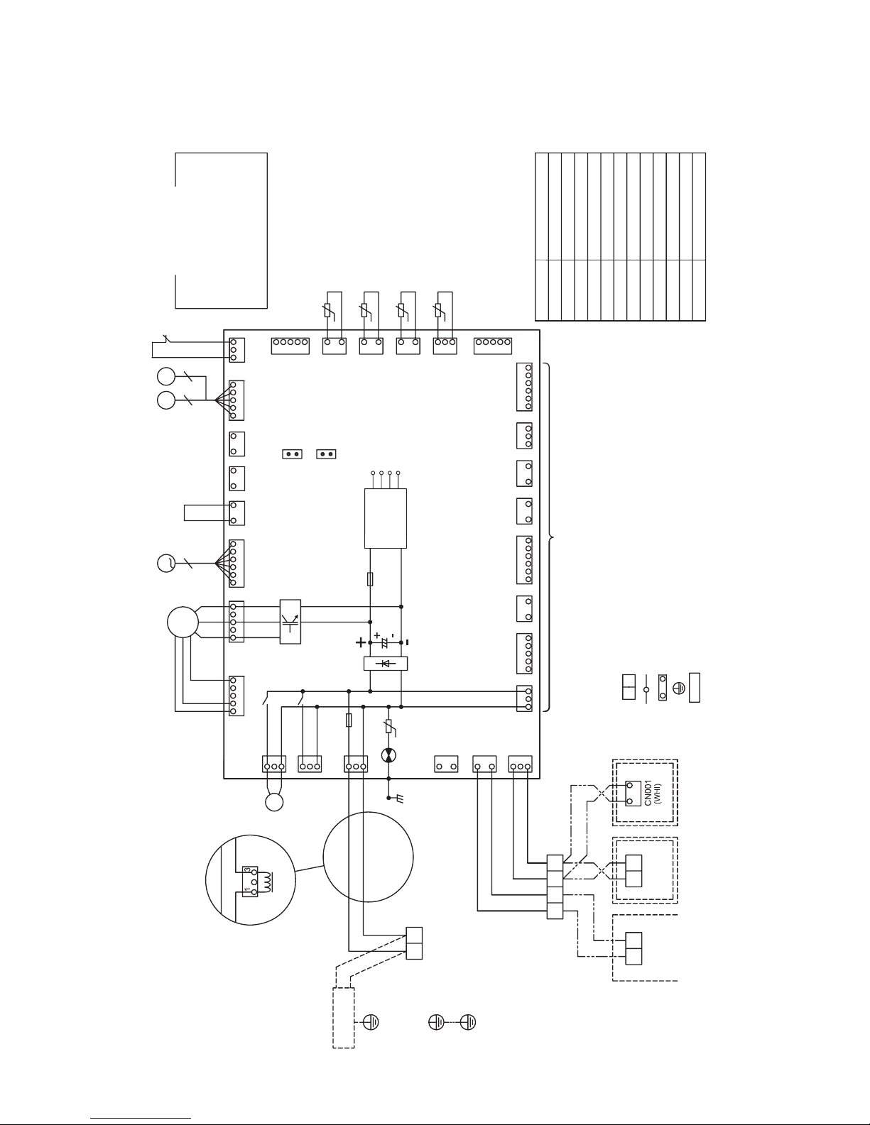
Color Indication
GRY: GRAY
GRN: GREEN
BRW: BROWN
Symbol
CN**DMF301, 302FMFS
LM1, 2
PMVLRY302, 303TATB1, 2
TC1, TC2, TCJ
Parts name
Connector
Drain pump Motor
Fuse
Fan Motor
Float Switch
Louver Motor
Pulse Motor Valve
Relay
Reactor
Indoor temp. sensor
Terminal Block
Temp. sensor
RED: RED
WHI: WHITE
YEL: YELLOW
BLU: BLUE
BLK: BLACK
CN81
(BLK)
CN104
(YEL)
CN102
(RED)
CN101
(BLK)
CN100
(BRW)
N50
(WHI)
TCJ
TC2
TC1
(FLEX)
TA
DC20V
DC16V
DC12V
DC7V
Control P.C. board for Indoor unit
CN73
(RED)
CN80
(GRN)
CN61
(YEL)
Wired
Remote controller
Adapter for
Wireless
Remote controller
BLU
BLK
BLK
BLK
BLK
Flow selector unit
Earth screw
Indoor unit
Earth screw
Power supply
1 ~ 50Hz 220V-240V
1 ~ 60Hz 220V
TB1
R(L)
t˚
t˚
t˚
t˚
1. Long dashed double short dashed line indicate the wiring site.
Broken line indicate the accessories.
2. indicates the terminal block.
indicates the connection terminal.
indicates the connector on the control P.C. board.
3. indicates the protection ground.
4. indicates the control P.C. board.
4. WIRING DIAGRAM
4-1. 2-Way Air Discharge Cassette Type

30
Red
White Black
Red
White Black
5. PARTS RATING
5-1. Parts Rating
5-1-1. 2-Way Air Discharge Cassette Type
Model name
Fan motor
Drain pump motor
Float switc
TA sensor
TC1 sensor
TC2 sensor
TCJ sensor
Pulse motor
PMV
MMU-
AP0072WH AP0092WH AP0122WH AP0152WH AP0182WH AP0242WH AP0272WH AP0302WH
SWF-230-60-1R SWF-280-60-1R
ADP-1409
FS-0218-103
Lead wire length 268 mm
Ø4 size lead wire length : 1200 mm, vinyl tube (Blue)
Ø6 size lead wire length : 1200 mm vinyl tube (Black)
Ø6 size lead wire length : 1200 mm vinyl tube (Red)
EMD-MD12TF-3
EFM-25YGTF-1 EFM-40YGTF-2
Model name
Fan motor
Drain pump motor
Float switc
TA sensor
TC1 sensor
TC2 sensor
TCJ sensor
Pulse motor
PMV
MMU-
AP0362WH AP0482WH AP0562WH
SWF-280-120-2R
ADP-1409
FS-0218-103
Lead wire length : 268 mm
Ø4 size lead wire length : 1200 mm vinyl tube (Blue)
Ø6 size lead wire length : 1200 mm vinyl tube (Black)
Ø6 size lead wire length : 1200 mm vinyl tube (Red)
EMD-MD12TF-3
EFM-60YGTF-1
5-1-2. Indoor Unit (Other Parts)
No.
1
2
Part name
Fan motor
(Model: SWF-230-60-1R)
Fan Motor
(Model: SWF-280-120-2R)
Checking procedure
Measure the resistance value of winding by using the tester.
Position
Red - White
White - Black
Black – Red
Resistance value
87 ± 8.7 Ω
Under 20°C
Measure the resistance value of winding by using the tester.
Position
Red - White
White - Black
Black – Red
Resistance value
37 ± 3.7 Ω
Under 20°C
 Loading...