


Toshiba MMD-AP0091BH, MMD-AP0071BH, MMD-AP0361BH, MMD-AP0481BH, MMD-AP0121BH INSTALLATION MANUAL
...INSTALLATION MANUAL
SUPER MODULAR MULTI SYSTEM AIR CONDITIONER
For commercial use (Not accessible to the general public)
Indoor Unit
<Concealed Duct Type>
MMD-AP0071BH, AP0091BH, AP0121BH, MMD-AP0151BH, AP0181BH, AP0241BH, MMD-AP0271BH, AP0301BH, AP0361BH, MMD-AP0481BH, AP0561BH
Thank you very much for purchasing TOSHIBA Air Conditioner.
Please read this owner's manual carefully before using your Air Conditioner.
• Be sure to obtain the “Owner’s manual” and “Installation manual” from constructor (or dealer).
Request to constructor or dealer
Please clearly explain the contents of the Owner’s manual and hand over it.
ADOPTION OF NEW REFRIGERANT
This Air Conditioner is a new type which adopts a new refrigerant HFC (R410A) instead of the conventional refrigerant R22 in order to prevent destruction of the ozone layer.
CONTENTS |
|
|
Accessory parts and Parts to be procured locally |
........................................... 3 |
|
1 |
PRECAUTIONS FOR SAFETY .................................................................... |
4 |
2 |
SELECTION OF INSTALLATION PLACE ................................................... |
5 |
3 |
INSTALLATION OF INDOOR UNIT ............................................................. |
7 |
4 |
DRAIN PIPING WORK ................................................................................. |
9 |
5 |
REFRIGERANT PIPING ............................................................................. |
11 |
6 |
ELECTRIC WORK ..................................................................................... |
13 |
7 |
APPLICABLE CONTROLS ........................................................................ |
17 |
8 |
TEST RUN .................................................................................................. |
20 |
9 |
TROUBLESHOOTING ............................................................................... |
22 |
10 |
MAINTENANCE ......................................................................................... |
27 |
2
Accessory parts and Parts to be procured locally
H Accessory parts
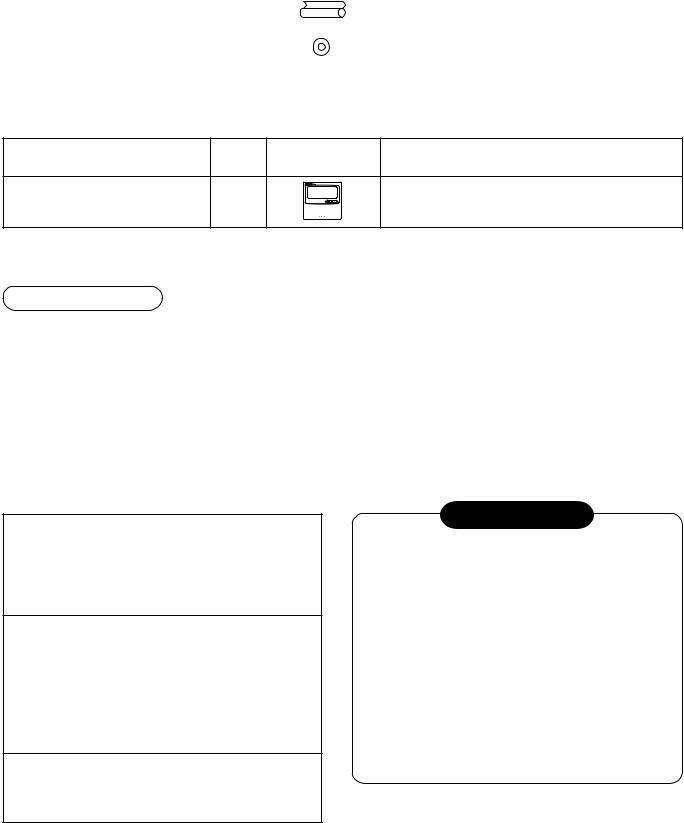
Part name |
Q’ty |
Shape |
Usage |
|
|
|
|
Installation Manual |
1 |
This manual |
(Be sure to hand over to customers) |
|
|
|
|
Heat insulating pipe |
2 |
|
For heat insulation of pipe connecting section |
|
|
|
|
Washer |
8 |
M10 × Ø34 |
For hanging-up unit |
|
|
|
|
|
|
|
|
<Separate sold parts>
Part name |
Q’ty |
Shape |
Usage |
Standard wired remote controller |
1 |
|
Model: RBC-AMT21E |
Refrigerant piping
•Piping material used for the conventional refrigerant cannot be used.
•Use copper pipe with 0.8 mm or more thickness for Ø6.4, Ø9.5, Ø12.7. Use copper pipe with 1.0 mm or more thickness for Ø15.9.
•Flare nut and flare works are also different from those of the conventional refrigerant. Take out the flare nut attached to the indoor unit of the air conditioner, and use it.
H Parts to be procured locally
Connecting pipe (Liquid side)
(6.4mm (diam.), Nominal (diam.) 1/4” thick 0.8mm) MMD-AP0071BH to MMD-AP0181BH
(9.5mm (diam.), Nominal (diam.) 3/8” thick 0.8mm) MMD-AP0241BH to MMD-AP0561BH
Connecting pipe (Gas side)
(9.5mm (diam.), Nominal (diam.) 3/8” thick 0.8mm) MMD-AP0071BH to MMD-AP0121BH
(12.7mm (diam.), Nominal (diam.) 1/2” thick 0.8mm) MMD-AP0151BH to MMD-AP0181BH
(15.9mm (diam.), Nominal (diam.) 5/8” thick 1.0mm) MMD-AP0241BH to MMD-AP0561BH
Power supply cord Cable 3-core 2.5mm2,
in conformity with Design 60245 IEC57
INFORMATION
•In this air conditioner, a Direct current motor is adopted for the indoor fan motor.
The current limit control works in the characteristics of direct current motor.
When exchanging a high-performance filter with new one or opening the service board, be sure to stop the fan; otherwise a protective control works resulted in stop of the air conditioner, and then an error code [P12] may be output.
However it is not a trouble.
After the desired operation has finished, reset the earth leak breaker of the indoor unit and push the operation STOP button on the remote controller to return the operation to the usual operation.
3
1 PRECAUTIONS FOR SAFETY
•Ensure that all Local, National and International regulations are satisfied.
•Read this “PRECAUTIONS FOR SAFETY” carefully before Installation.
•The precautions described below include the important items regarding safety. Observe them without fail.
•After the installation work, perform a trial operation to check for any problem.
Follow the Owner’s Manual to explain how to use and maintain the unit to the customer.
•Turn off the main power supply switch (or breaker) before the unit maintenance.
•Ask the customer to keep the Installation Manual together with the Owner’s Manual.
CAUTION New Refrigerant Air Conditioner Installation
•THIS AIR CONDITIONER ADOPTS THE NEW HFC REFRIGERANT (R410A) WHICH DOES NOT DESTROY OZONE LAYER.
The characteristics of R410A refrigerant are ; easy to absorb water, oxidizing membrane or oil, and its pressure is approx. 1.6 times higher than that of refrigerant R22. Accompanied with the new refrigerant, refrigerating oil has also been changed. Therefore, during installation work, be sure that water, dust, former refrigerant, or refrigerating oil does not enter the refrigerating cycle.
To prevent charging an incorrect refrigerant and refrigerating oil, the sizes of connecting sections of charging port of the main unit and installation tools are charged from those for the conventional refrigerant.
Accordingly the exclusive tools are required for the new refrigerant (R410A).
For connecting pipes, use new and clean piping designed for R410A, and please care so that water or dust does not enter. Moreover, do not use the existing piping because there are problems with pressure-resistance force and impurity in it.
CAUTION To Disconnect the Appliance from Main Power Supply.
This appliance must be connected to the main power supply by means of a switch with a contact separation of at least 3 mm.
 WARNING
•Ask an authorized dealer or qualified installation professional to install/maintain the air conditioner.
Inappropriate installation may result in water leakage, electric shock or fire.
•Turn off the main power supply switch or breaker before attempting any electrical work.
Make sure all power switches are off. Failure to do so may cause electric shock.
•Connect the connecting wire correctly.
If the connecting wire is connected in a wrong way, electric parts may be damaged.
•When moving the air conditioner for the installation into another place, be very careful not to enter any gaseous matter other than the specified refrigerant into the refrigeration cycle.
If air or any other gas is mixed in the refrigerant, the gas pressure in the refrigeration cycle becomes abnormally high and it as a result causes pipe burst and injuries on persons.
•Do not modify this unit by removing any of the safety guards or by by-passing any of the safety interlock switches.
•Exposure of unit to water or other moisture before installation may cause a short-circuit of electrical parts.
Do not store it in a wet basement or expose to rain or water.
•After unpacking the unit, examine it carefully if there are possible damage.
•Do not install in a place that might increase the vibration of the unit.
•To avoid personal injury (with sharp edges), be careful when handling parts.
•Perform installation work properly according to the Installation Manual.
Inappropriate installation may result in water leakage, electric shock or fire.
•When the air conditioner is installed in a small room, provide appropriate measures to ensure that the concentration of refrigerant leakage occur in the room does not exceed the critical level.
4
•Install the air conditioner securely in a location where the base can sustain the weight adequately.
•Perform the specified installation work to guard against an earthquake.
If the air conditioner is not installed appropriately, accidents may occur due to the falling unit.
•If refrigerant gas has leaked during the installation work, ventilate the room immediately.
If the leaked refrigerant gas comes in contact with fire, noxious gas may generate.
•After the installation work, confirm that refrigerant gas does not leak.
If refrigerant gas leaks into the room and flows near a fire source, such as a cooking range, noxious gas might generate.
•Electrical work must be performed by a qualified electrician in accordance with the Installation Manual. Make sure the air conditioner uses an exclusive power supply.
An insufficient power supply capacity or inappropriate installation may cause fire.
•Use the specified wires for wiring connect the terminals securely fix.
To prevent external forces applied to the terminals from affecting the terminals.
•Conform to the regulations of the local electric company when wiring the power supply.
Inappropriate grounding may cause electric shock.
•Do not install the air conditioner in a location subject to a risk of exposure to a combustible gas.
If a combustible gas leaks, and stays around the unit, a fire may occur.
2 SELECTION OF INSTALLATION PLACE
WARNING
•Install the air conditioner at enough strong place to withstand the weight of the unit.
If the strength is not enough, the unit may fall down resulting in injury.
•Install the air conditioner at a height 2.5m or more from the floor.
If you insert your hands or others directly into the unit while the air conditioner operates, it is dangerous because you may contact with revolving fan or active electricity.
CAUTION
Upon approval of the customer, install the air conditioner in a place that satisfies the following conditions.
•Place where the unit can be installed horizontally.
•Place where a sufficient servicing space can be ensured for safety maintenance and check.
•Place where drained water will not cause any problem.
Avoid installing in the following places.
•Place exposed to air with high salt content (seaside area), or place exposed to large quantities of sulfide gas (hot spring). (Should the unit be used in these places, special protective measures are needed.)
•Place exposed to oil, vapor, oil smoke or corrosive gas.
•Place where organic solvent is used nearby.
•Place close to a machine generating high frequency.
•Place where the discharged air blows directly into the window of the neighboring house. (For outdoor unit)
•Place where noise of the outdoor unit is easily transmitted.
(When installing the air conditioner on the boundary with the neighbor, pay due attention to the level of noise.)
•Place with poor ventilation.
(Before air ducting work, check whether value of air volume, static pressure and duct resistance are correct.)
5
2 SELECTION OF INSTALLATION PLACE
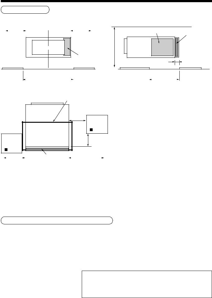
Installation space
Reserve space required for maintenance the indoor unit and service work.
700mm *1 |
|
|
|
|
700mm *1 |
|
|
|
|||||
|
|
|
|
|
|
|
|
|
|
|
|
|
|
Air outlet
Electric parts box
Electric parts box
Air filter
400mm (Min.)
25mm
|
|
|
|
Ceiling opening |
Ceiling opening size C |
|
|
size D |
|
|
|
|
|
|
|
Air outlet |
Ceiling opening part |
|
|
|
|
|
(150mm) |
|
|
Check port A |
|
|
450mm |
Check port B |
|
300mm |
|
|
|
450mm |
|
|
|
|
|
Air filter |
|
|
|
|
|
|
|
|
|
|
700mm for maintenance of air filter |
|
700mm for |
||||
|
|
|
|
|
maintenance of air filter |
|
Notes)
*1 Be sure that space with 700mm or more is reserved for attachment/detachment at the taking-out direction of the air filter.
*2 Be sure to set a check port (A) for the refrigerant piping, drain piping, maintenance of drain pan, etc; otherwise maintenance for devices is unavailable.
*3 If the taking-out direction of the air filter is set at the left side, be sure to set a check port (B) at the left side of the set for attachment/detachment of the air filter. If there is no check port (B), the air filter cannot be attached or detached.
*4 Be sure to set a ceiling opening for maintenance of the electric ports such as fan motor; otherwise maintenance for electric parts such as fan motor is unavailable.
MODEL MMD-AP |
0071BH to 0121BH |
0151BH to 0181BH |
0241BH to 0301BH |
0361BH to 0561BH |
|
|
|
|
|
Set width (mm) |
550 |
700 |
1000 |
1350 |
|
|
|
|
|
Air filter width (mm) |
508 |
655 |
960 (480 2) |
1310 (655 2) |
|
|
|
|
|
Ceiling opening size C |
600 |
750 |
1050 |
1400 |
|
|
|
|
|
Ceiling opening size D |
470 |
470 |
470 |
470 |
|
|
|
|
|
Installation under high-humidity atmosphere
In some cases including the rainy season, especially inside of the ceiling may become high-humidity atmosphere (dew-point temperature: 23°C or higher).
1.Installation to inside of the ceiling with tiles on the roof
2.Installation to inside of the ceiling with slated roof
3.Installation to a place where inside of the ceiling is used for pathway to intake the outside air
•In the above cases, additionally attach the thermal insulator (Glass wool, etc.) to all positions of the air conditioner, which come to contact with the high-humidity atmosphere. In this case, arrange the side plate (Service plate) so
that it is easily removed.
•Apply also a sufficient thermal insulation to the duct and connecting part of the duct.
[Reference] Dewing test conditions
Indoor side: 27°C dry bulb temperature 24°C wet bulb temperature
Air volume: Low air volume, operation time 4 hours
6
The lighting term setup of the filter sign (Notification of filter cleaning) of the remote controller can be changed according to the condition of installation.
If the room is not heated due to the installation place or construction of the room, the detection temperature of heating can be raised.
For setup method, refer to “Change of lighting term of filter sign” and “To secure better effect of heating” in the Applicable controls of this Manual.
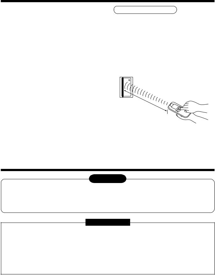
In case of wireless type
The sensor of indoor unit with wireless remote controller can receive a signal within approx. 8m.
Based upon it, determine a place where the remote controller is operated and the installation place of the indoor unit.
•To prevent a malfunction, select a place where is not influenced by a florescent light or direct sunlight.
•Two or more (Up to 6 units) indoor units with wireless remote controller can be installed in the same room.
Within |
8m |
|
3 INSTALLATION OF INDOOR UNIT
WARNING
Install the air conditioner certainly to sufficiently withstand the weight.
If the strength is insufficient, the unit may fall down resulting in human injury.
Perform a specified installation work to guard against strong wind or earthquake.
An incomplete installation can cause accidents by the units falling and dropping.
REQUIREMENT
Strictly comply with the following rules to prevent damage of the indoor units and human injury.
•Do not put a heavy article on the indoor unit. (Even units are packaged)
•Carry in the indoor unit as it is packaged if possible.
If carrying in the indoor unit unpacked by necessity, be sure to use buffering cloth, etc. to not damage the unit.
•To move the indoor unit, hold the hooking metals (4 positions) only.
Do not apply force to the other parts (refrigerant pipe, drain pan, foamed parts, or resin parts, etc.).
•Carry the package by two or more persons, and do not bundle it with PP band at positions other than specified.
7

3 INSTALLATION OF INDOOR UNIT
External view
129
|
|
Knock-out hole Ø125 |
||||
110 |
|
(Air take-in port) |
||||
|
||||||
|
|
|
|
|
|
|
|
|
|
|
|
|
|
|
|
|
|
|
|
|
|
|
|
|
|
|
|
|
Drain pipe connecting port for vinyl chloride pipe |
||||||||
|
(Inner dia. 32, VP. 25) |
|
|
|
|
|
|
||
Refrigerant pipe connecting port |
75 |
Main unit dimension 800 |
|
|
|||||
(Gas side ØF) |
|
|
|
||||||
|
|
|
|
|
|
|
|
|
|
|
Hanging bolt |
41 |
Hanging bolt pitch 700 |
|
|
|
|||
Hanging bolt pitch B |
4-M10 screw |
|
50 |
|
638 |
59 |
|
|
|
(Arranged locally) |
|
|
|
|
|||||
|
|
|
|
|
|||||
Main unit dimension A |
|
|
|
|
|
498 |
|
|
|
|
|
|
41 |
|
393 |
|
|
|
|
|
|
|
13150 |
243 |
|
|
174 |
320 |
|
|
44 |
|
|
196 |
|
||||
|
|
|
|
|
|
|
|
||
|
49 |
|
|
|
|
|
|
|
|
|
|
|
|
|
|
|
|
|
|
6-Ø4 Tapping screw hole Ø160
• Wired remote controller (RBC-AMT21E)
4 |
2.7 |
120
16
120
Refrigerant pipe connecting port (Liquid side ØG)
Ø26 Power supply, remote controller cable take-out port
Model MMD- |
A |
B |
F |
G |
|
|
|
|
|
AP0071BH, AP0091BH, AP0121BH |
550 |
616 |
9.5 |
6.4 |
|
|
|
|
|
AP0151BH, AP0181BH |
700 |
766 |
12.7 |
6.4 |
|
|
|
|
|
AP0241BH, AP0271BH, AP0301BH |
1000 |
1066 |
15.9 |
9.5 |
|
|
|
|
|
AP0361BH, AP0481BH, AP0561BH |
1350 |
1416 |
15.9 |
9.5 |
|
|
|
|
|
|
Opening hole on ceiling and placing of hanging bolt |
|
|
|
||
• |
Considering the indoor unit and the hanged-up piping/wiring work, determine the installation position and direction. |
|||||
• |
After installation position of the indoor unit has been determined, open a hole on the wiring and place the hanging bolt. |
|||||
• |
For opening size of the ceiling and the hanging bolt pitch, see the external view. |
|
|
|
||
• |
When the ceiling has already boarded, draw the drain pipe, refrigerant pipe, inter-unit wire between indoor and |
|||||
|
outdoor units, central control system wire, and remote controller wire up to the position where pipes and wires |
|||||
|
are connected before hanged-up the indoor unit. |
|
|
|
|
|
|
Hanging bolt |
|
M10 or W3/8 |
4 pieces |
|
|
The hanging bolts and nuts will be procured locally. |
|
|
||||
|
|
|
|
|
||
Nut |
|
M10 or W3/8 |
12 pieces |
|
||
|
|
|
|
|||
|
|
|
|
|
|
|
Installation of hanging bolt
Use M10 hanging bolts (4 pcs, to be local procure).
Matching to the existing structure, set pitch according to size in the unit external view as shown below.
|
New concrete slab |
Steel flame structure |
Existing concrete slab |
||
Install the bolts with insert brackets or anchor |
Use existing angles or install new |
Use a hole-in anchors, hole-in |
|||
bolts. |
|
|
support angles. |
|
plugs, or a hole-in bolts. |
|
|
|
Hanging bolt |
|
|
|
|
Reinforcing |
|
|
|
|
|
steel |
|
|
|
|
|
Anchor bolt |
|
|
|
(Blade type |
(Slide type |
(Pipe hanging |
|
|
|
bracket) |
bracket) |
anchor bolt) |
Hanging bolt |
Support angle |
|
Installation of indoor unit
•Attach the nuts (M10 or W3/8: Procured locally) and the attached washers (Ø34) to the hanging bolt.
•Put washers at up and down of T-groove of the hanging bracket of the indoor unit to hang down the indoor unit.
•Using a level vial, check that four sides are horizontal. (Horizontal degree: Within 5mm)
Hanging bolt |
(1) |
M10 flat washer |
|
(W3/8 or M10) |
(Accessory) |
Nut |
(2) |
(W3/8 or M10) |
|
|
M10 flat washer |
Nut |
(Accessory) |
(W3/8 or M10) |
|
(1)Required those other than M10 flat washer at site.
(2)To prevent falling-off of bolt (safety), be sure to set it just under the hanging bracket as shown in the figure.
8
Installation of remote controller (Sold separately)
For installation of the remote controller, follow to the Installation Manual attached to the remote controller.
•Do not put the remote controller on the place where is exposed to direct sunlight or near a stove, etc.
•Operating the remote controller, check the indoor unit surely receives the signal, and then install the remote controller. (Wireless type)
•Install the remote controller 1m apart from the devices such as TV or stereo. (Image may be disturbed or noise may be output.) (Wireless type)
4 DRAIN PIPING WORK
CAUTION
•Following the Installation Manual, perform the drain piping work so that water is properly drained, and apply a heat insulation so as not to cause a dew. Inappropriate piping work may result in water leakage in the room and wet of furniture.
Pipe material/Insulator and size
The following materials for piping work and insulating process are procured locally.
Pipe material
Hard vinyl chloride pipe VP25 (Outer diameter Ø32mm)
Insulator
Foamed polyethylene foam, thickness: 10mm or more
REQUIREMENT
•Be sure to perform heat insulation of the drain pipes of the indoor unit.
•Never forget to perform heat insulation of the connecting part with the indoor unit. An incomplete heat insulation causes dewing.
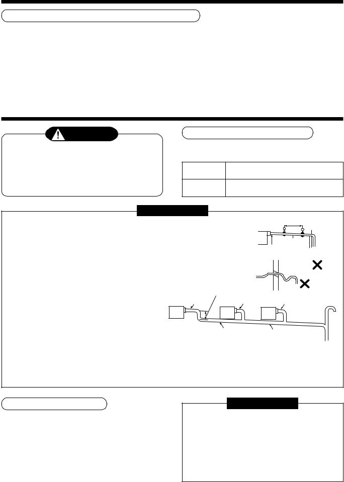
Heat
• Set the drain pipe with downward slope (1/100 or more), and do not insulator make swelling or trap on the piping. It may cause an abnormal sound.
•For length of the traversing drain pipe, restrict to 20m or less. In case of a long pipe, provide support brackets with interval of 1.5 to 2m in order to prevent waving.
As long as possible (10cm)
• Set the collective piping as shown in the right figure.
• Do not mount an air purge pipe, |
VP25 |
VP25 |
|
|
|
otherwise drain water spouts |
(Collective pipes) |
|
out resulted in water leak. |
|
|
1.5m to 2m |
Support |
|
bracket |
1/100 or more downward
Arched shape
Trap
VP25
VP30 or more
•The hard vinyl-chloride pipe cannot be directly connected to
the drain pipe connecting port of the indoor unit. For connection with the drain pipe connecting port, be sure to fix the attached flexible hose.
Downward slope 1/100 or more
•Adhesive agent cannot be used for the pipe connecting port (hard socket) of the indoor unit.
Be sure to use the attached hose band for fixing, otherwise damage or water leakage of the drain pipe connecting port is caused.
Connection of drain pipe
•Connect the hard socket (Procured locally) to the hard socket side of the attached flexible hose which has been installed.
•Connect the drain pipes (Procured locally) successively to the connected the hard socket.
REQUIREMENT
•Using adhesive agent for vinyl chloride, connect the hard vinyl chloride pipes certainly so that water does not leak.
•It requires several times to dry and harden the adhesive agent.
(Refer to Guide Manual of the adhesive agent.) In this time, be sure not to apply force to the connecting section with the drain pipes.
9
 Loading...