


Telefunken TFMM5560, TFMM5400, TFMM5380, TFMM5370, TFMM5360 Datasheet
...TFMM5..0
Vishay Telefunken
Photo Modules for PCM Remote Control Systems
Available types for different carrier frequencies
Type |
fo |
Type |
fo |
TFMM 5300 |
30 kHz |
TFMM 5330 |
33 kHz |
TFMM 5360 |
36 kHz |
TFMM 5370 |
36.7 kHz |
TFMM 5380 |
38 kHz |
TFMM 5400 |
40 kHz |
|
|
|
|
TFMM 5560 |
56 kHz |
|
|
Description
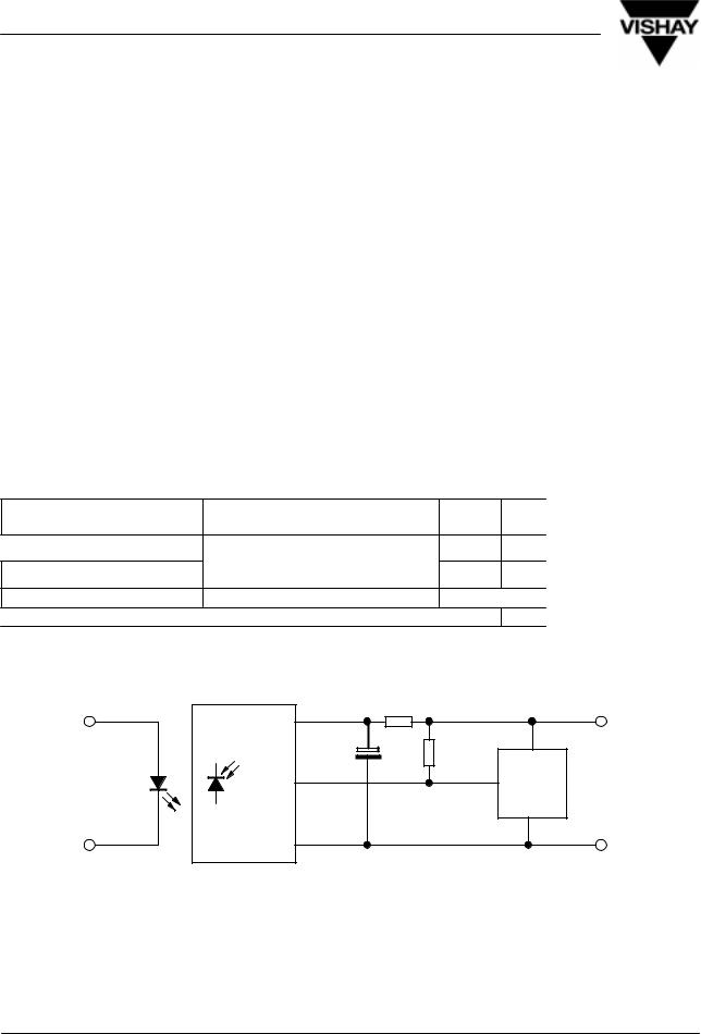
The TFMM5..0 ± series are miniaturized receivers for infrared remote control systems. PIN diode and preamplifier are assembled on PC board, the epoxy package is designed as IR filter.
The demodulated output signal can directly be decoded by a microprocessor. The main benefit is the reliable function even in disturbed ambient and the protection against uncontrolled output pulses.
95 10266
Features
Photo detector and preamplifier in one package |
5 Volt supply voltage, low power consumption |
||
|
Output active low |
TTL and CMOS compatibility |
|
Internal filter for PCM frequency |
|
Continuous transmission possible (tpi/T 0.4) |
|
High immunity against ambient light |
|
SMD |
|
|
High shielding against electric field disturbance |
|
|
Block Diagram
|
|
|
2 |
Input |
|
Control |
VS |
|
|
||
|
Circuit |
|
|
|
|
100 k |
|
|
|
|
|
|
|
|
3 |
PIN |
|
|
OUT |
|
|
|
|
|
AGC |
Band |
Demodu- |
|
Pass |
lator |
|
|
|
||
|
|
|
1 |
|
|
|
GND |
|
|
|
94 8136 |
DocumentNumber 82003 |
www.vishay.com |
Rev. 3, 14-Sep-00 |
1 (10) |
TFMM5..0
Vishay Telefunken
Absolute Maximum Ratings
Tamb = 25_C |
|
|
|
|
Parameter |
Test Conditions |
Symbol |
Value |
Unit |
Supply Voltage |
(Pin 2) |
VS |
±0.3...6.0 |
V |
Supply Current |
(Pin 2) |
IS |
5 |
mA |
Output Voltage |
(Pin 3) |
VO |
±0.3...6.0 |
V |
Output Current |
(Pin 3) |
IO |
5 |
mA |
Junction Temperature |
|
Tj |
100 |
C |
Storage Temperature Range |
|
Tstg |
±40...+85 |
C |
Operating Temperature Range |
|
Tamb |
±25...+85 |
C |
Power Consumption |
(Tamb 85 C) |
Ptot |
50 |
mW |
Soldering Temperature |
t 10 s, 1 mm from case |
Tsd |
230 |
C |
Basic Characteristics
Tamb = 25_C |
|
|
|
|
Parameter |
|
Test Conditions |
Symbol |
Min |
Supply Current (Pin 2) |
VS = 5 |
V, Ev = 0 |
ISD |
0.4 |
|
VS = 5 |
V, Ev = 40 klx, sunlight |
ISH |
|
Transmission Distance |
Ev = 0, test signal see fig.7, |
d |
|
|
|
IR diode TSIP5201, IF = 1.5 A |
|
|
|
Output Voltage Low (Pin 3)
 Irradiance (30 ± 40 kHz)
Irradiance (56 kHz)
Irradiance
 Directivity
IOSL = 0.5 mA,Ee = 0.7 mW/m2, f = fo, tp/T = 0.4
Pulse width tolerance:
tpo = tpi±160 ms,
test signal (see fig.7)
 Angle of half transmission distance
VOSL
Ee min
Ee min
Ee max  20
20
ϕ1/2
Typ |
Max |
Unit |
0.5 |
0.8 |
mA |
1.0 |
|
mA |
35 |
|
m |
|
|
|
|
250 |
mV |
|
|
|
0.6 |
|
mW/m2 |
0.8 |
|
mW/m2 |
|
|
W/m2 |
±40 |
|
deg |
Application Circuit
|
|
330 *) |
+ 5 V **) |
|
|
2 |
|
|
TFM. 5..0 |
4.7 mF *) |
>10 k |
|
|
||
|
|
|
|
TSUS 5... |
|
|
optional |
|
3 |
mC |
|
TSIP 5... |
|
||
|
|
||
|
|
|
|
|
94 8137 |
1 |
GND |
|
|
||
|
|
|
|
|
|
*) only necessary to suppress power supply disturbances |
|
|
|
**) tolerated supply voltage range : 4.5V< VS < 5.5 V |
|
www.vishay.com |
DocumentNumber 82003 |
2 (10) |
Rev. 3, 14-Sep-00 |

TFMM5..0
Vishay Telefunken
Typical Characteristics (Tamb = 25_C unless otherwise specified)
ResponsitivityRel.± |
1.0 |
|
|
|
|
|
|
|
|
|
|
|
|
|
|
|
|
|
|
|
|
|
|
|
|
|
|
|
|
|
|
||
0.8 |
|
|
|
|
|
|
|
|
|
|
|
|
|
|
|
|
|
|
|
|
|
|
|
|
|
|
|
|
|
|
|
||
|
|
|
|
|
|
|
|
|
|
|
|
|
|
|
|
|
|
0.6 |
|
|
|
|
|
|
|
|
|
|
|
|
|
|
|
|
|
|
|
|
|
|
|
|
|
|
|
|
|
|
|
|
|
|
|
|
|
|
|
|
|
|
|
|
|
|
|
|
|
/e E |
0.4 |
|
|
|
|
|
|
|
|
|
|
|
|
|
|
|
|
|
|
|
|
|
|
|
|
|
|
|
|
|
|
||
|
|
|
|
|
|
|
|
|
|
|
|
|
|
|
||
|
|
|
|
|
|
|
|
|
|
|
|
|
|
|
|
|
E min |
0.2 |
|
|
|
|
|
|
|
|
|
|
|
|
|
|
|
|
|
|
|
|
|
f = f0"5% |
|
|
|
|
|
|
|
|||
|
|
|
|
|
|
|
|
|
|
|
|
|
||||
|
|
|
|
|
|
|
|
|
|
|
|
|
|
|||
e |
|
|
|
|
|
Df ( 3 dB ) = f0 / 10 |
|
|
|
|
|
|||||
|
0.0 |
|
|
|
|
|
|
|
|
|
||||||
|
|
|
|
|
|
|
|
|
|
|||||||
|
|
|
|
|
|
|
|
|
|
|
|
|
|
|
|
|
|
0.7 |
0.8 |
0.9 |
1.0 |
1.1 |
|
1.2 |
1.3 |
||||||||
94 8143 |
|
|
|
|
f / f0 ± Relative Frequency |
|
|
|
|
|||||||
Figure 1. Frequency Dependence of Responsivity
) |
4 |
|
|
|
|
|
|
|
|
|
|
|
|
|
|
|
|
|
|
|
|
|
|
|
|
|
|
||
2 |
|
|
|
|
|
|
|
|
|
|
|
|
|
|
( mW/m |
3 |
|
|
|
|
|
|
|
|
|
|
|
|
|
|
|
|
|
|
|
|
|
|
|
|
|
|
||
Irradiance |
2 |
|
|
|
|
|
|
|
|
|
|
|
|
|
|
|
|
|
|
|
|
|
|
|
|
|
|
||
Threshold |
1 |
|
|
|
|
|
|
|
|
|
|
|
|
|
± |
|
|
|
|
|
|
|
|
|
|
|
|
|
|
e min |
|
|
|
|
|
|
|
|
|
|
|
|
|
|
E |
|
|
|
|
|
|
|
|
|
|
|
|
|
|
|
0 |
|
|
|
|
|
|
|
|
|
|
|
|
|
|
0 |
0.4 |
0.8 |
1.2 |
1.6 |
|
2.0 |
|||||||
95 10188 |
|
|
E ± Field Strength of Disturbance ( kV / m ) |
|
|
|||||||||
Figure 4. Sensitivity vs. Electric Field Disturbances
|
1000 |
|
( ms ) |
800 |
Input Burst Duration |
Length |
600 |
|
Pulse |
|
|
|
|
|
± Output |
400 |
|
200 |
|
|
tpo |
|
l = 950 nm, Optical Test Signal, Fig.7
0 |
|
|
|
|
|
|
|
|
|
|
|
|
|
|
|
|
|
|
|
|
|
|
|
|
|
0.1 |
1 |
|
|
10 |
100 |
1000 |
10000 |
||||||||||||||||||
95 10187 |
|
|
|
|
E |
e |
± Irradiance ( mW / m2 ) |
|
|
||||||||||||||||
|
|
|
|
|
|
|
|
|
|
|
|
|
|
|
|
|
|
|
|
|
|
|
|
|
|
Figure 2. Sensitivity in Dark Ambient
) |
100 |
|
2 |
|
|
( mW/m |
f = f0 |
|
|
||
Irradiance |
10 |
|
10 kHz |
||
Threshold |
||
1 |
||
100 Hz |
||
± |
||
e min |
|
|
E |
|
|
|
0.1 |
0.1 1 10 100 1000
95 10194 DVs RMS ± AC Voltage on DC Supply Voltage ( mV )
Figure 5. Sensitivity vs. Supply Voltage Disturbances
) |
10 |
|
|
|
|
) |
1.0 |
2 |
|
|
|
|
|
2 |
|
( mW/m |
|
|
|
|
|
( mW/m |
0.8 |
Irradiance |
1 |
|
|
|
|
Irradiance |
0.6 |
Threshold± |
|
|
|
|
|
Threshold± |
0.4 |
|
|
|
|
|
|
|
|
e min |
|
|
|
|
|
e min |
0.2 |
|
|
|
|
|
|
||
E |
|
|
|
|
|
E |
|
|
0.1 |
|
|
|
|
|
0.0 |
|
0.01 |
0.1 |
1 |
10 |
100 |
|
±30 |
95 10189 |
E ± Irradiance ( W / m2 ) |
|
95 10195 |
||||
Sensitivity in dark Ambient
0 30 60 90 Tamb ± Ambient Temperature ( °C )
Figure 3. Sensitivity in Bright Ambient |
Figure 6. Sensitivity vs. Ambient Temperature |
|
|
DocumentNumber 82003 |
www.vishay.com |
Rev. 3, 14-Sep-00 |
3 (10) |
 Loading...