Telefunken TLRY4420, TLRO4420, TLRH4420, TLRG4420 Datasheet

TLR.442.
Vishay Telefunken
Resistor LED for 12 V Supply Voltage
Color |
Type |
Technology |
Angle of Half Intensity |
|
|
|
±ö |
High efficiency red |
TLRH4420 |
GaAsP on GaP |
30° |
Soft orange |
TLRO4420 |
GaAsP on GaP |
30° |
Yellow |
TLRY4420 |
GaAsP on GaP |
30° |
Green |
TLRG4420 |
GaP on GaP |
30° |
Description |
94 8488 |
|
|
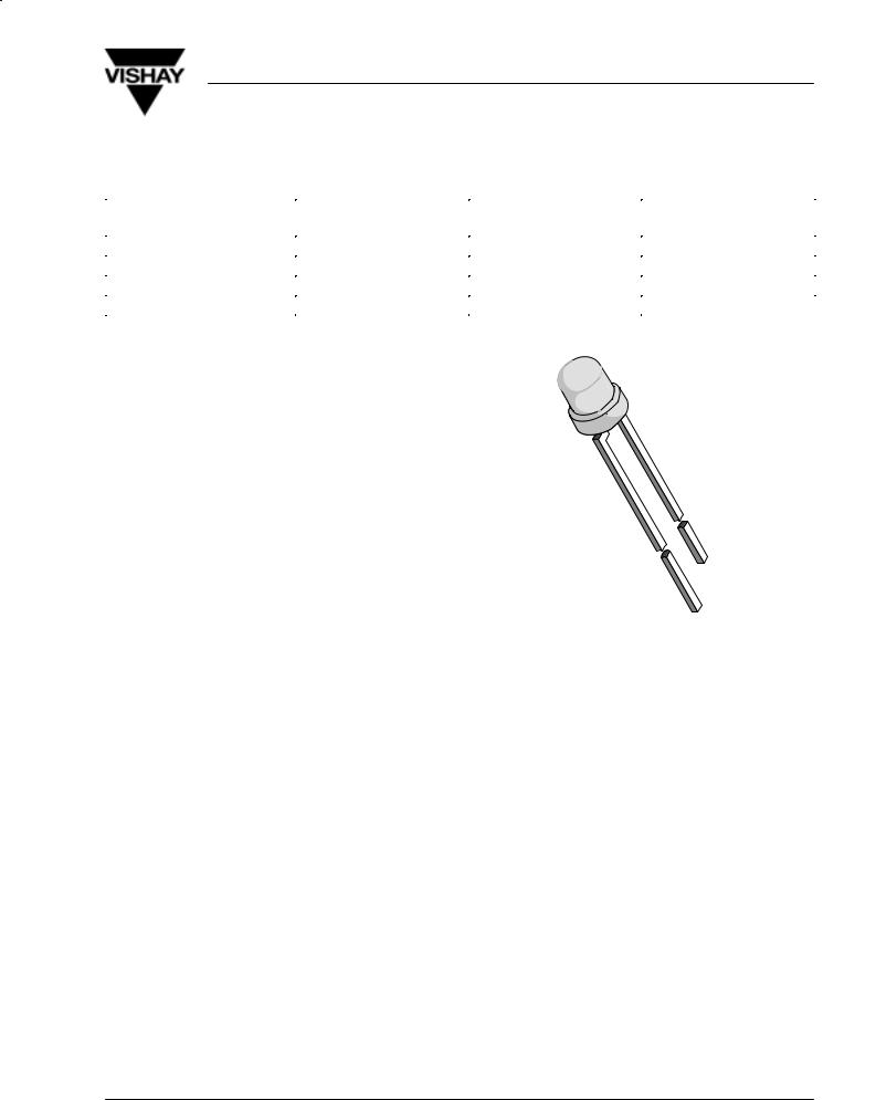
These devices are developed for the automotive |
|
industry with special requirements as for EMC (electro |
|
magnetic compatibility) in motor vehicles with 12 V |
|
supply voltage. |
|
They are resistant against transient conduction (high |
|
voltage spikes) and interferences by conduction and |
|
coupling. |
|
The TLR.442. series contains an integrated resistor for |
|
current limiting in series with the LED chip. This allows |
|
the lamp to be driven from a 12 V source without an |
|
external current limiter. |
|
Available colors are red, soft orange, yellow and |
|
green. These tinted diffused lamps provide a wide |
|
off-axis viewing angle. |
|
These LEDs are intended for space critical |
|
applications such as automobile instrument panels, |
|
switches and others which are driven from a 12 V |
|
source. |
|
Features
DWith current limiting resistor for 12 V
DEMC specified (DIN 40 839)
DResistant against transient high voltage spikes
DCost effective: save space and resistor cost
DStandard ù 3 mm (T-1) package
DWide viewing angle
DChoice of four bright colors
DLuminous intensity categorized
DYellow and green color categorized
Applications
Status light in cars
OFF / ON indicator in cars
Background illumination for switches
Off / On indicator in switches
Document Number 83045 |
www.vishay.de •FaxBack +1-408-970-5600 |
Rev. A1, 04-Feb-99 |
1 (9) |

TLR.442.
Vishay Telefunken
Absolute Maximum Ratings
Tamb = 25_C, unless otherwise specified
TLRH4420 ,TLRO4420 ,TLRY4420 ,TLRG4420 ,
Parameter |
Test Conditions |
Symbol |
Value |
Unit |
Reverse voltage |
|
VR |
6 |
V |
Forward voltage |
Tamb ≤ 65°C |
VF |
16 |
V |
Power dissipation |
Tamb ≤ 65°C |
PV |
240 |
mW |
Junction temperature |
|
Tj |
100 |
°C |
Storage temperature range |
|
Tstg |
±55 to +100 |
°C |
Soldering temperature |
t ≤ 5 s, 2 mm from body |
Tsd |
260 |
°C |
Thermal resistance junction/ambient |
|
RthJA |
150 |
K/W |
Optical and Electrical Characteristics
Tamb = 25_C, unless otherwise specified
High efficiency red (TLRH4420 )
Parameter |
Test Conditions |
Type |
Symbol |
Min |
Typ |
Max |
Unit |
Luminous intensity |
VF = 12 V |
|
IV |
1.6 |
4 |
|
mcd |
Dominant wavelength |
VF = 12 V |
|
ld |
612 |
|
625 |
nm |
Peak wavelength |
VF = 12 V |
|
lp |
|
635 |
|
nm |
Angle of half intensity |
VF = 12 V |
|
ϕ |
|
±30 |
|
deg |
Forward current |
VS = 12 V |
|
IF |
|
10 |
12 |
mA |
Breakdown voltage |
IR = 10 mA |
|
VBR |
6 |
70 |
|
V |
Junction capacitance |
VR = 0, f = 1 MHz |
|
Cj |
|
50 |
|
pF |
Soft orange (TLRO4420 ) |
|
|
|
|
|
|
|
|
|
|
|
|
|
|
|
Parameter |
Test Conditions |
Type |
Symbol |
Min |
Typ |
Max |
Unit |
Luminous intensity |
VF = 12 V |
|
IV |
4 |
10 |
|
mcd |
Dominant wavelength |
VF = 12 V |
|
ld |
598 |
|
611 |
nm |
Peak wavelength |
VF = 12 V |
|
lp |
|
605 |
|
nm |
Angle of half intensity |
VF = 12 V |
|
ϕ |
|
±30 |
|
deg |
Forward current |
VS = 12 V |
|
IF |
|
10 |
12 |
mA |
Breakdown voltage |
IR = 10 mA |
|
VBR |
6 |
70 |
|
V |
Junction capacitance |
VR = 0, f = 1 MHz |
|
Cj |
|
50 |
|
pF |
Yellow (TLRY4420 ) |
|
|
|
|
|
|
|
|
|
|
|
|
|
|
|
Parameter |
Test Conditions |
Type |
Symbol |
Min |
Typ |
Max |
Unit |
Luminous intensity |
VF = 12 V |
|
IV |
1.6 |
4 |
|
mcd |
Dominant wavelength |
VF = 12 V |
|
ld |
581 |
|
594 |
nm |
Peak wavelength |
VF = 12 V |
|
lp |
|
585 |
|
nm |
Angle of half intensity |
VF = 12 V |
|
ϕ |
|
±30 |
|
deg |
Forward current |
VS = 12 V |
|
IF |
|
10 |
12 |
mA |
Breakdown voltage |
IR = 10 mA |
|
VBR |
6 |
70 |
|
V |
Junction capacitance |
VR = 0, f = 1 MHz |
|
Cj |
|
50 |
|
pF |
www.vishay.de •FaxBack +1-408-970-5600 |
Document Number 83045 |
2 (9) |
Rev. A1, 04-Feb-99 |

TLR.442.
Vishay Telefunken
Green (TLRG4420 )
Parameter |
Test Conditions |
Type |
Symbol |
Min |
Typ |
Max |
Unit |
Luminous intensity |
VF = 12 V |
|
IV |
1.6 |
4 |
|
mcd |
Dominant wavelength |
VF = 12 V |
|
ld |
562 |
|
575 |
nm |
Peak wavelength |
VF = 12 V |
|
lp |
|
565 |
|
nm |
Angle of half intensity |
VF = 12 V |
|
ϕ |
|
±30 |
|
deg |
Forward current |
VS = 12 V |
|
IF |
|
10 |
12 |
mA |
Breakdown voltage |
IR = 10 mA |
|
VBR |
6 |
70 |
|
V |
Junction capacitance |
VR = 0, f = 1 MHz |
|
Cj |
|
50 |
|
pF |
Typical Characteristics (Tamb = 25_C, unless otherwise specified)
|
20 |
|
|
|
|
|
|
|
|
|
|
|
18 |
High Efficiency Red |
|
|
|
|
|
||||
|
|
|
|
|
|
|
|
|
|
|
|
) |
16 |
|
|
|
|
|
|
|
|
|
|
|
|
|
|
|
|
|
|
|
|
|
|
( mA |
14 |
|
|
|
|
|
|
|
|
|
|
12 |
|
|
|
|
|
|
|
|
|
|
|
Current |
|
|
|
|
|
|
|
|
|
|
|
10 |
|
|
|
|
|
|
|
|
|
|
|
8 |
|
|
|
|
|
|
|
|
|
|
|
± Forward |
|
|
|
|
|
|
|
|
|
|
|
6 |
|
|
|
|
|
|
|
|
|
|
|
4 |
|
|
|
|
|
|
|
|
|
|
|
F |
2 |
|
|
|
|
|
|
|
|
|
|
I |
|
|
|
|
|
|
|
|
|
|
|
|
|
|
|
|
|
|
|
|
|
|
|
|
0 |
|
|
|
|
|
|
|
|
|
|
|
0 |
2 |
4 |
6 |
8 |
10 |
12 |
14 |
16 |
18 |
20 |
95 11434 |
|
|
|
VF ± Forward Voltage ( V ) |
|
|
|||||
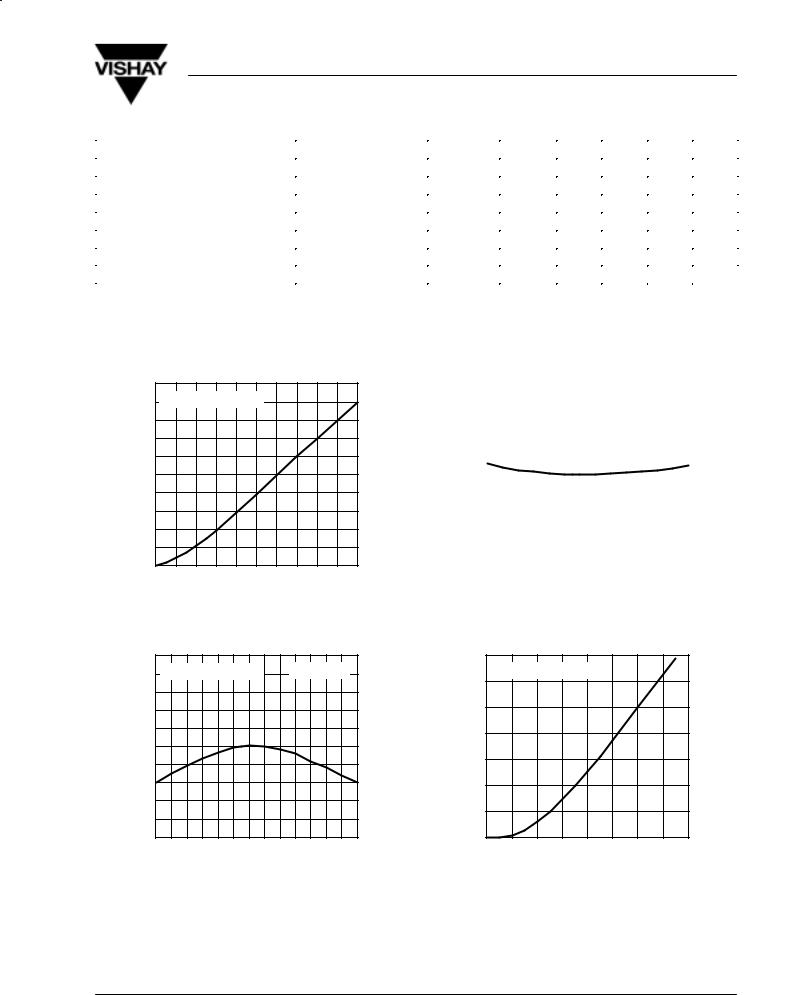
Figure 1 Forward Current vs. Forward Voltage
|
1.5 |
|
|
|
|
1.4 |
High Efficiency Red |
VS = 12 V |
|
Current |
1.3 |
|
|
|
1.2 |
|
|
|
|
Forward |
1.1 |
|
|
|
1.0 |
|
|
|
|
|
|
|
|
|
± Relative |
0.9 |
|
|
|
0.8 |
|
|
|
|
0.7 |
|
|
|
|
Frel |
|
|
|
|
0.6 |
|
|
|
|
I |
|
|
|
|
|
|
|
|
|
|
0.5 |
|
|
|
|
±30±20±10 0 |
10 20 30 40 50 60 70 80 90 100 |
||
95 11435 |
Tamb ± Ambient Temperature ( °C ) |
|||
Figure 2 Relative Forward Current vs. Ambient Temperature
|
1.5 |
|
|
|
|
|
|
|
|
|
|
|
|
|
|
|
|
|
|
|
|
|
|
|
|
|
|
|
|
|
|
|
|
|
|
|
|
|
|
Voltage |
1.4 |
|
High Efficiency Red |
|
|
IF = 10 mA |
|
|
|||||||||||
|
|
|
|
||||||||||||||||
1.3 |
|
|
|
|
|
|
|
|
|
|
|
|
|
|
|
|
|
|
|
|
|
|
|
|
|
|
|
|
|
|
|
|
|
|
|
|
|
|
|
Forward |
1.2 |
|
|
|
|
|
|
|
|
|
|
|
|
|
|
|
|
|
|
|
|
|
|
|
|
|
|
|
|
|
|
|
|
|
|
|
|
||
1.0 |
|
|
|
|
|
|
|
|
|
|
|
|
|
|
|
|
|
|
|
Relative± |
1.1 |
|
|
|
|
|
|
|
|
|
|
|
|
|
|
|
|
|
|
0.9 |
|
|
|
|
|
|
|
|
|
|
|
|
|
|
|
|
|
|
|
|
|
|
|
|
|
|
|
|
|
|
|
|
|
|
|
|
|
|
|
|
0.8 |
|
|
|
|
|
|
|
|
|
|
|
|
|
|
|
|
|
|
|
|
|
|
|
|
|
|
|
|
|
|
|
|
|
|
|
|
|
|
Frel |
0.7 |
|
|
|
|
|
|
|
|
|
|
|
|
|
|
|
|
|
|
|
|
|
|
|
|
|
|
|
|
|
|
|
|
|
|
|
|
||
|
|
|
|
|
|
|
|
|
|
|
|
|
|
|
|
|
|
|
|
V |
0.6 |
|
|
|
|
|
|
|
|
|
|
|
|
|
|
|
|
|
|
|
|
|
|
|
|
|
|
|
|
|
|
|
|
|
|
|
|
|
|
|
0.5 |
|
|
|
|
|
|
|
|
|
|
|
|
|
|
|
|
|
|
|
|
|
|
|
|
|
|
|
|
|
|
|
|
|
|
|
|
|
|
|
±30±20±10 0 |
10 20 30 40 50 60 70 80 90 100 |
|||||||||||||||||
95 11436 |
|
|
Tamb ± Ambient Temperature ( °C ) |
||||||||||||||||
Figure 3 Relative Forward Voltage vs.
Ambient Temperature
|
1.4 |
|
|
|
|
|
|
|
|
Intensity |
1.2 |
High Efficiency Red |
|
|
|
|
|||
|
|
|
|
|
|
|
|
||
1.0 |
|
|
|
|
|
|
|
|
|
Luminous |
0.8 |
|
|
|
|
|
|
|
|
0.6 |
|
|
|
|
|
|
|
|
|
± Relative |
|
|
|
|
|
|
|
|
|
0.4 |
|
|
|
|
|
|
|
|
|
|
|
|
|
|
|
|
|
|
|
Vrel |
0.2 |
|
|
|
|
|
|
|
|
I |
|
|
|
|
|
|
|
|
|
|
0 |
|
|
|
|
|
|
|
|
|
0 |
2 |
4 |
6 |
8 |
10 |
12 |
14 |
16 |
95 11456 |
|
VF ± Forward Voltage ( V ) |
|
|
|||||
Figure 4 Relative Luminous Intensity vs. Forward Voltage
Document Number 83045 |
www.vishay.de •FaxBack +1-408-970-5600 |
Rev. A1, 04-Feb-99 |
3 (9) |
 Loading...