


TLHY5401
Telefunken TLHY5401, TLHY5405, TLHY5400, TLHR5400, TLHR5405 Datasheet
...
TLH.54../64..
Vishay Telefunken
1 (9)
Rev. A1, 04-Feb-99
www.vishay .de • FaxBack +1-408-970-5600
Document Number 83012
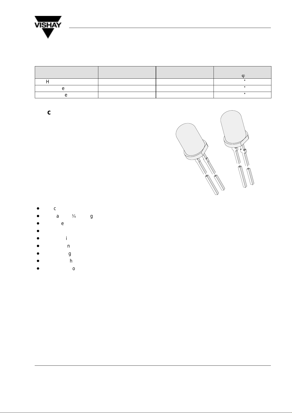
High Efficiency LED in ø 5 mm Tinted Diffused Package
Color Type Technology Angle of Half Intensity
±
ö
High efficiency red TLHR54../TLHR64.. GaAsP on GaP 30
°
Yellow TLHY54../TLHY64.. GaAsP on GaP 30
°
Green TLHG54../TLHG64.. GaP on GaP 30
°
Description
The TLH.54.. and 64.. series was developed for
standard applications like general indicating and
lighting purposes.
It is housed in a 5 mm tinted diffused plastic package.
The wide viewing angle of these devices provides a
high on-off contrast.
Several selection types with different luminous
intensities are offered. All LEDs are categorized in
luminous intensity groups. The green and yellow LEDs
are categorized additionally in wavelength groups.
That allows users to assemble LEDs with uniform
appearance.
Features
D
Choice of three bright colors
D
Standard T-1
¾
package
D
Small mechanical tolerances
D
Suitable for DC and high peak current
D
Wide viewing angle
D
Luminous intensity categorized
D
Yellow and green color categorized
D
TLH.54.. with stand-offs
D
TLH.64.. without stand-offs
96 11663
TLH.62.. TLH.52..
Applications
Status lights
OFF / ON indicator
Background illumination
Readout lights
Maintenance lights
Legend light
TLH.54../64..
Vishay Telefunken
2 (9)
Rev. A1, 04-Feb-99
www.vishay .de • FaxBack +1-408-970-5600 Document Number 83012
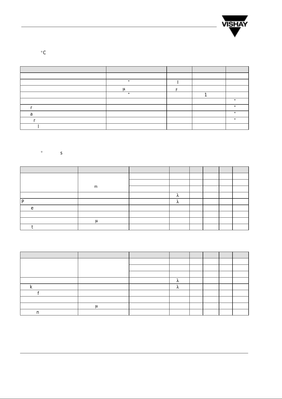
Absolute Maximum Ratings
T
amb
= 25
_
C, unless otherwise specified
TLHR54../TLHR64.. ,TLHY54../TLHY64.. ,TLHG54../TLHG64.. ,
Parameter Test Conditions Symbol Value Unit
Reverse voltage V
R
6 V
DC forward current T
amb
≤ 65
°
C I
F
30 mA
Surge forward current t
p
≤ 10
m
s I
FSM
1 A
Power dissipation T
amb
≤ 65
°
C P
V
100 mW
Junction temperature T
j
100
°
C
Operating temperature range T
amb
–20 to +100
°
C
Storage temperature range T
stg
–55 to +100
°
C
Soldering temperature t ≤ 5 s, 2 mm from body T
sd
260
°
C
Thermal resistance junction/ambient R
thJA
350 K/W
Optical and Electrical Characteristics
T
amb
= 25
_
C, unless otherwise specified
High efficiency red (TLHR54../TLHR64.. )
Parameter Test Conditions Type Symbol Min Typ Max Unit
TLHR5400/6400 I
V
1.6 3.5 mcd
Luminous intensity
I
F
=
10
m
A
,
TLHR5401/6401 I
V
4 7 mcd
y
I
Vmin
/I
Vmax
≥
0
.
5
TLHR5405/6405 I
V
6.3 10 mcd
Dominant wavelength I
F
= 10 mA
l
d
612 625 nm
Peak wavelength I
F
= 10 mA
l
p
635 nm
Angle of half intensity I
F
= 10 mA ϕ ±30 deg
Forward voltage I
F
= 20 mA V
F
2 3 V
Reverse voltage I
R
= 10
m
A V
R
6 15 V
Junction capacitance V
R
= 0, f = 1 MHz C
j
50 pF
Yellow (TLHY54../TLHY64.. )
Parameter Test Conditions Type Symbol Min Typ Max Unit
TLHY5400/6400 I
V
1.6 3.5 mcd
Luminous intensity
I
F
=
10
m
A
,
TLHY5401/6401 I
V
4 7 mcd
y
I
Vmin
/I
Vmax
≥
0
.
5
TLHY5405/6405 I
V
6.3 10 mcd
Dominant wavelength I
F
= 10 mA
l
d
581 594 nm
Peak wavelength I
F
= 10 mA
l
p
585 nm
Angle of half intensity I
F
= 10 mA ϕ ±30 deg
Forward voltage I
F
= 20 mA V
F
2.4 3 V
Reverse voltage I
R
= 10
m
A V
R
6 15 V
Junction capacitance V
R
= 0, f = 1 MHz C
j
50 pF
TLH.54../64..
Vishay Telefunken
3 (9)
Rev. A1, 04-Feb-99
www.vishay .de • FaxBack +1-408-970-5600
Document Number 83012
Green (TLHG54../TLHG64.. )
Parameter Test Conditions Type Symbol Min Typ Max Unit
TLHG5400/6400 I
V
1.6 4 mcd
Luminous intensity
I
F
=
10
m
A
,
TLHG5401/6401 I
V
4 7 mcd
y
I
Vmin
/I
Vmax
≥
0
.
5
TLHG5405/6405 I
V
6.3 15 mcd
Dominant wavelength I
F
= 10 mA
l
d
562 575 nm
Peak wavelength I
F
= 10 mA
l
p
565 nm
Angle of half intensity I
F
= 10 mA ϕ ±30 deg
Forward voltage I
F
= 20 mA V
F
2.4 3 V
Reverse voltage I
R
= 10
m
A V
R
6 15 V
Junction capacitance V
R
= 0, f = 1 MHz C
j
50 pF
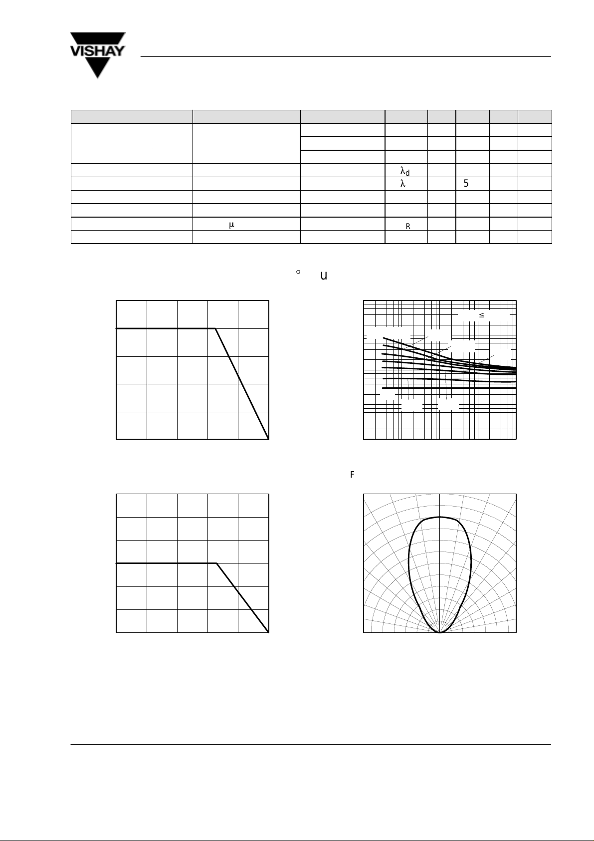
Typical Characteristics (T
amb
= 25
_
C, unless otherwise specified)
020406080
0
25
50
75
100
125
P – Power Dissipation ( mW )
V
T
amb
– Ambient Temperature ( °C )
100
95 10918
Figure 1 Power Dissipation vs. Ambient Temperature
0
10
20
30
40
60
020406080
I – Forward Current ( mA )
F
T
amb
– Ambient Temperature ( °C )
100
95 10046
50
Figure 2 Forward Current vs. Ambient Temperature
0.01 0.1 1 10
1
10
100
1000
10000
t
p
– Pulse Length ( ms )
100
95 10025
I – Forward Current ( mA )
F
t
p
/T=0.01
0.02
0.05
0.1
0.2
1
0.5
T
amb
v
65°C
Figure 3 Forward Current vs. Pulse Length
0.4 0.2 0 0.2 0.4
0.6
95 10042
0.6
0.9
0.8
0°
30°
10
°
20
°
40°
50°
60°
70°
80°
0.7
1.0
I – Relative Luminous Intensity
v rel
Figure 4 Rel. Luminous Intensity vs.
Angular Displacement
 Loading...