


Tecfluid LC-40 ADF User Manual

Level Detector
Series
instrumentación
para fluidos
LC-40 ADF
Instructions Manual
Technical Data
• Mounting: Vertical / Side mounting.
• Fittings: EN 1092-1 DN-65 Flanges
Others on demand
• Minimum liquid density: 0.45 kg/l
• Liquid viscosity: maximum 3.000 mPa.s
• Repeatability: ±3 mm of the level .
• Materials: EN 1.4404 (AISI-316L)
On demand: PTFE, PVC, PP, PVDF
• Electrical housing: Metal alloy aluminium
without copper
• Pressure: PN-16
On demand: PN-40 ... PN-400
• Liquid temperature:
Depends on the material, see page 3
• Ambient temperature range: -20…+40 ºC
• Degree of protection: IP67
• Complies with 97/23/EC Directive
for pressure vessels.
R-MI-LC40ADF Rev.:0 English Version
This equipment is considered as being a
!
pressure accessory and NOT a safety
accessory as defined in the 97/23/EC
directive, Article 1, paragraph 2.1.3.
Operation
The changes in level are followed by the float
mounted on a pivoted arm.
On the opposite end from the float there is a
sealed permanent magnet which acts on
another magnet, situated in the inside of the
electrical housing, that acts on the limit
switches.
Applications:
• Liquid storage tanks
• Hot water storage.
• Control of steam condensates storage
tanks .
• On-Off of pumps.
• Maximum and minimum level control.
RECEPTION
The LC-40 level detectors are supplied individually packed for protection d uring transport .
On reception of the level detector, check:
− That the float pivots freely in the fork that supports it.
− That the pivot shaft has the two split pins, one on each end.
Important:
!
If the operation of the limit switches is checked before installation, this must be done in a non
hazardous area.
To check the limit switch, unscrew the electrical housing cover to gain access to the electrical
connections.
Move manually the float from the bottom stop to the top stop of the fork.
The signal at the electrical connection terminals will vary according to the float’s position (with the
AMM and AMR this can be checked using a multimeter).
Once the correct working of the complete s ystem has been checked, mount the level detector as
described below.
MOUNTING
The models designed to be mounted in the side of the tank should be installed in a position so that
the float can move freely in a vertical plane.
The LC-40V y LC-40VR models require installation in the top of the tank.
!
Important:
Check that the working pressure is not above that specified on the instrument’s identification label.
Check that the ambient and liquid temperatures are within the limits specified on pages 2 & 3.
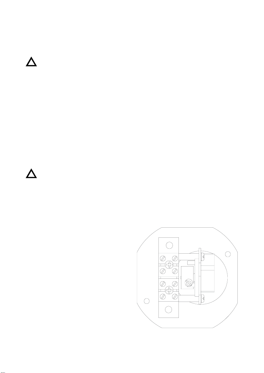
Limit switch characteristics and connections.
Maximum ambient temperature: 40 ºC
AMM: Vmax: 250 V
Imax: 3 A
1. Earth
2. Common
3. Normally closed
4. Normally open
AMD: Vnom: 8.2 VDC
Max. level I > 2.2 mA
Min. level I < 1.1 mA
1. Earth
2. Positive
3. Negative
4. Not connected
AMR: Vmax: 250 V
Imax: 0.5 A
Pmax: 60 VA
1. Earth
2. Common
3. Normally closed
4. Normally open
1
2
3
4
2