


3-868-019-01(1)
TSL-S11000
DDS Autoloader Unit
User’s Guide ––––––––––––––––––– page 2
Mode d’emploi –––––––––––––––– page 35
Bedienungsanleitung –––––––– Seite 68
Guía del usario –––––––––––––––– página 101
©1999 Sony Corporation

Safety Regulations
Owner’s Record
The model and serial numbers are located on the rear. Record the serial number in the space provided below.
Refer to them whenever you call upon your Sony dealer regarding this product.
|
Model No. |
|
Serial No. |
|
|
||
|
|
|
|
|
|
|
|
|
|
|
|
Information
WARNING
To prevent fire or shock hazard, do not expose the unit to rain or moisture.
To avoid electrical shock, do not open the cabinet. Refer servicing to qualified personnel only.
For the customers in the U.S.A.
You are cautioned that any changes or modifications not expressly approved in this manual could void your authority to operate this equipment.
WARNING
Note: This equipment has been tested and found to comply with the limits for a Class B digital device, pursuant to Part 15 of the FCC Rules. These limits are designed to provide reasonable protection against harmful interference in a residential installation. This equipment generates, uses and can radiate radio frequency energy and, if not installed and used in accordance with the instructions, may cause harmful interference to radio communications. However, there is no guarantee that interference will not occur in a particular installation. If this equipment does cause harmful interference to radio or television reception, which can be determined by turning the equipment off and on, the user is encouraged to try to correct the interference by one or more of the following measures:
•Reorient or relocate the receiving antenna
•Increase the separation between the equipment and receiver.
•Connect the equipment into an outlet on a circuit different from that to which the receiver is connected.
•Consult the dealer or an experienced radio/TV technician for help.
This device requires shielded interface cables to comply with FCC emission limits.
2

Table of Contents
Chapter 1
Introduction
Chapter 2
Preparation
Chapter 3
Operation
Chapter 4
Care and
Maintenance
Appendix
About the DDS Autoloader Unit ....................................................... |
5 |
Features .................................................................................................... |
5 |
Useable Cartridges ................................................................................... |
5 |
System Components ................................................................................ |
6 |
Part Names and Functions ............................................................... |
7 |
Front Panel ............................................................................................... |
7 |
Rear Panel .............................................................................................. |
10 |
Magazine ............................................................................................... |
11 |
Supplied Items ................................................................................. |
12 |
Interconnections ............................................................................. |
13 |
SCSI ID Setting ................................................................................ |
14 |
Option Switches (DIP Switch) .............................................................. |
15 |
Menu Settings and Checks ............................................................ |
16 |
Loading Cartridges into the Magazine .......................................... |
21 |
Removing Cartridges from the Magazine ............................................. |
23 |
How to Use the DDS Auto Loader Unit ......................................... |
26 |
Data Cartridge Selection ........................................................................ |
27 |
Ejecting the Magazine ........................................................................... |
28 |
Taking Care of the Autoloader Unit ............................................... |
29 |
Safety Considerations ............................................................................ |
29 |
Avoiding Damage .................................................................................. |
29 |
Other precautions ................................................................................... |
30 |
Taking Care of Magazines and Cartridges .................................... |
31 |
Use Precautions ..................................................................................... |
31 |
Storage Precautions ............................................................................... |
32 |
Head Cleaning ................................................................................. |
33 |
How to Clean ......................................................................................... |
33 |
Specifications .................................................................................. |
34 |
Performance ........................................................................................... |
34 |
Operating Environment ......................................................................... |
34 |
Power Supply & Miscellaneous ............................................................ |
34 |
|
Declaration of Conformity |
Trade Name: |
Sony |
Model No.: |
TSL-S11000 |
Responsible Party: |
Sony Electronics Inc. |
Address: |
1 Sony Drive, Park Ridge, NJ. 07656 USA |
Telephone No.: |
201-930-6970 |
This device complies with Part 15 of the FCC Rules. Operation is subject to the following two conditions:
(1) This device may not cause harmful interference, and
(2) This device must accept any interference received, including interference that may cause undesired operation.
English
Table of Contents |
3 |

How to Use this Guide
This Guide describes the DDS Autoloader Unit TSL-S11000, and how to take care of it. Please read it carefully before using the unit, and keep it handy for future reference.
The Guide consists of four parts, plus the specifications. Refer to the parts that relate to your use of the unit.
Chapter 1 describes the features of the unit, its system components, and the name and function of each part.
Chapter 2 describes the necessary connections between the unit and the host computer. If other SCSI devices are being used, you may need to change the SCSI ID setting. Read this part if you are installing the unit.
Chapter 3 describes how to use the LCD (display), and handling of magazines and cartridges. Notes on handling magazines and cartridges. Refer to this information when using the machine.
Chapter 4 describes how to take care of the unit, cartridges and magazines, and how to clean the drive heads. Read this part before using the unit.
The Specifications appendix provides the major specifications of the TSL-
S11000.
4

 Chapter 1 Introduction
About the DDS Autoloader Unit
The TSL-S11000 is a DDS autoloader unit containing a built-in DDS drive unit SDT-11000. The magazine provided with the unit accommodates eight data cartridges, and data cartridges set into the magazine are automatically loaded into the SDT-11000. (Either 1 or 7 cartridges can be used in the unit at one time.)
The built-in SDT-11000 supports the DDS, DDS-2, DDS-3 and DDS-4 data formats.
Features
The DDS Autoloader Unit TSL-S11000 has the following features:
•A highly-durable linear guide mechanism provides automatic loading/ unloading of data cartridges to the built-in DDS drive unit SDT-11000.
•The Digital Data Storage format provides a huge data storage capacity on DDS-4 data cartridges.
•Read After Write Function and third-level error correction code guarantee high data reliability.
•When data is recorded using data compression together with 150-meter DDS-4 data cartridges, you can record up to 20 to 40 gigabytes of data on a single data cartridge.*1
•Stored data are automatically checked for compression. The drive unit can read uncompressed data written by earlier-model drives.
•Features an embedded SCSI interface (Ultra/Wide, single-ended or lowvoltage differential).
•Read/Write operation is available with the DDS, DDS-2, DDS-3 and DDS-4 formats.
*1 |
The degree of data compression attained while recording data varies |
|
|
|
according to system environment and data type. |
Useable Cartridges
Data cartridges used with the TSL-S11000 must be marked with the DDS,
DDS-2, DDS-3 or DDS-4 logo.
DDS-4 Logo |
DDS-3 Logo |
DDS-2 Logo |
DDS logo |
Caution:
Be sure to use only the cartridges designed specifically for DDS (do not use
DAT cartridges for music).
Chapter 1 Introduction 5

System Components
The TSL-S11000 connects to the host computer via a Wide SCSI interface.
Host Computer
SCSI terminator
|
|
|
|
|
|
|
|
|
|
|
|
|
|
|
|
|
|
|
|
|
|
|
|
|
|
|
|
|
|
|
|
|
|
|
|
|
|
|
|
|
|
|
|
|
|
|
|
|
|
|
|
|
|
|
|
|
|
|
|
|
|
|
|
|
|
|
|
|
TSL-S11000 (this device) |
|
|
|
|
|
|
|
|
Peripheral devices |
|
|
|
|
|||||||||
Example of System Components
Note
In order to use the device as a LVD device, please use terminators that support LVD. Also, please make sure that all the devices attached to the SCSI bus support LVD. If these requirements are not met, the device will function as a SE device.
6 Chapter 1 Introduction

Part Names and Functions
Front Panel
1 2 3
POWER |
BUSY |
TAPE |
SELECT |
ENTER |
EJECT |
98 7 6 5 4
Front panel
1POWER Indicator
Lights while the autoloader is on.
2POWER Switch
Press to turn the autoloader on or off.
3Magazine receptacle
Insert a magazine here.
See page 26 and 28 for information on inserting and removing a magazine. See page 21 for information on inserting data cartridges.
4EJECT Button
Press this button to remove a magazine from the machine. It is also used for menu operations on the display.
5SELECT Button
Press this button to select a cartridge to be loaded. It is also used for menu operations on the display.
6ENTER Button
Press this button to load the cartridge selected by the SELECT button into the DDS drive. It is also used for menu operations on the display.
Chapter 1 Introduction 7
7Liquid Crystal Display (LCD)
Displays the machine’s status.
The orientation of the display can be changed to match the direction of viewing as described on page 19.
|
|
|
|
Horizontal Display |
|
|
|
|
Vertical Display |
|||||||
|
|
|
|
|
|
|
|
|
|
a |
|
|
|
|
|
|
|
|
|
|
|
|
|
|
|
|
|
|
|
|
|
|
|
a |
|
|
|
|
|
|
|
|
|
b |
|
|
|
|
|
|
|
|
|
|
|
|
|
|
|
|
|
|
|||||
|
|
|
|
|
|
|
|
|
|
c g |
|
|
|
|
|
f |
|
|
|
|
|
|
|
|
|
|
|
|
|
|
|
||
|
|
|
|
|
|
|
|
|
|
|
|
|
|
|
||
|
|
|
|
|
|
|
|
|
|
|
|
|
|
|
||
|
|
|
|
|
|
|
|
|
|
|
|
|
||||
|
|
|
|
|
|
|
|
|
|
|
|
|
|
|
||
|
|
|
|
|
|
|
|
|
|
d d |
|
|
|
|
|
|
|
|
|
|
|
|
|
|
|
|
|
|
|
|
|
||
|
|
|
|
|
|
|
|
|
|
|
|
|
|
|||
|
|
|
|
|
|
|
|
|
|
|
|
|
|
|
|
|
|
|
|
|
|
|
|
|
|
|
c |
|
|
|
|
|
b |
|
|
|
|
|
|
|
|
|
|
|
|
|
|
|
||
|
|
|
|
|
|
|
|
|
|
e |
|
|
|
|
|
|
|
|
g |
|
f e |
|
|
|
|
|
|
|
|||||
|
|
|
|
|
|
|
|
|
|
|
||||||
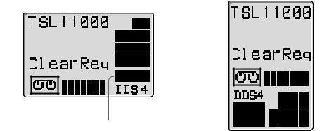
Liquid Crystal Display
a Message Area
Indicates the machine’s operating status.
Warning or error messages may be displayed here depending on the operating state.
The language of the messages may be selected from English, French, German and Spanish as described on page 20.
b Cartridge Number Indicator
Displays the status of the cartridge in the magazine. The cartridge number blinks while exchanging the cartridge. When a cartridge is loaded from a magazine to the DDS drive, the cartridge number disappears. When the cartridge is returned to the magazine, the number blinks again.
c Data Compression Indicator
This indicator lights when data compression is enabled for the drive.
d DDS Format Indicator
Indicates the format of the cartridge loaded in the DDS drive.
e Write-Protect Indicator
This indicator appears when the magazine or data cartridge is writeprotected by the write-protect tab.
8 Chapter 1 Introduction
f Tape Position Indicator
Indicates the winding position of the tape in the cartridge loaded in the DDS drive.
ppppppp pppp
Tape winding position indicated by the Tape Position Indicator
g Cartridge Indicator
This indicator appears when a cartridge is loaded in the internal DDS drive, and indicates the tape’s load status: when the tape is being loaded or unloaded from the drive, this indicator blinks.
8TAPE Indicator
Lights green when a data cartridge is loaded into the SDT-11000. The indicator flashes while a cartridge is being loaded or unloaded.
9BUSY Indicator
Lights green when the SCSI interface is ready for data transfer. This indicator flashes while data is being read from or written to the cartridge loaded into the DDS drive, while searching for data, or while the tape is being rewound.
Chapter 1 Introduction 9
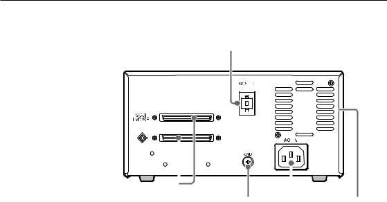
Rear Panel
1
|
|
|
|
|
|
|
|
|
|
|
|
|
|
|
|
|
|
|
|
|
|
|
|
|
|
|
|
|
|
|
|
|
|
|
|
|
|
|
|
|
|
|
|
|
|
|
|
|
|
|
|
|
|
|
|
|
|
|
|
|
|
|
|
|
|
|
|
|
|
|
|
|
|
|
|
|
|
|
|
|
|
|
|
|
|
|
|
|
|
|
|
|
|
|
|
|
|
|
|
|
|
|
|
|
|
|
|
|
|
|
|
|
|
|
|
|
|
|
|
|
|
|
|
|
|
|
|
|
|
|
|
|
|
|
|
|
|
|
|
|
|
|
|
|
|
|
|
|
|
|
|
|
|
|
|
|
|
|
|
|
|
|
|
|
|
|
|
|
5 |
4 |
|
|
3 |
2 |
|||||||
|
|
Rear panel |
|
|
|
|
|
|||||
1Rotary Selector Switch
SCSI ID selector (page 14).
2 Cooling Fan
3AC IN Connector
Connect the power cable here.
4GND (Ground) Terminal
Connect the ground terminals of other devices to the autoloader’s frame ground.
5SCSI Connector
Connects to the SCSI bus connector of the host computer or another SCSI peripheral.
10 Chapter 1 Introduction
Magazine
2
1
Magazine
1Stopper
Prevents loaded cartridges from slipping out of the magazine.
See page 21 and 23 for information on loading and removing cartridges.
2Write protect tab
Used to inhibit writes to data cartridges. Sliding this tab to the right write-protects all data cartridges, whether or not write protection is set on the individual data cartridges.
Caution:
The write protection status is determined by checking for the reflective plate on the weite protect tab. In order to ensure correct determination of the status, keep the plate reasonably clean, and never affix labels or the like over the write protect tab.
Chapter 1 Introduction 11

 Chapter 2 Preparation
After you confirm that you have all of the required accessories for your installation, connect the autoloader to the host computer (page 13), and select the SCSI ID with the rotary switch on the rear panel (page 14).
Supplied Items
When you first open the box, make sure it contains the following items.
Contact your supplier if anything is missing or broken.
•DDS Autoloader Unit
•Magazine
•Power Cable
•This Guide
12 Chapter 2 Preparation
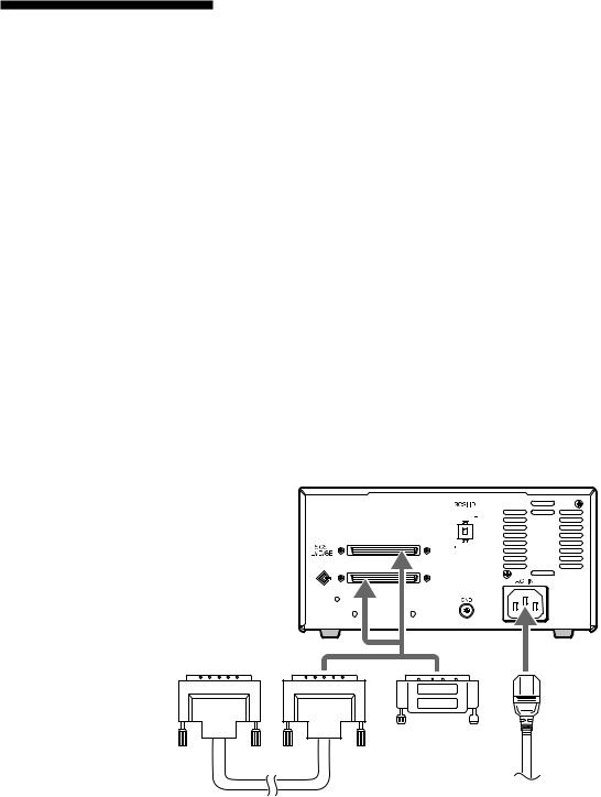
Interconnections
The SCSI bus allows connection of up to seven peripherals to the host computer. Use a SCSI cable with a High-Density 68 pin connector.
Precautions:
•Switch off the host computer and peripherals before connecting the SCSI cable.
•Make sure the SCSI connectors are pressed tightly together.
•If this unit is the last (or only) device on the SCSI bus, make sure to connect a SCSI bus terminator to the open connector.
•The TSL-S11000 supports both single-ended and low voltage differential SCSI configurations as set forth in the X3T10/1142D (SCSI Parallel Interface 2) Standard. Only unshielded connectors are supported. Possible cable and connector sources are listed below. This does not imply that these are the only sources for SCSI accessories.
Note
When using high speed data transfer with the TSL-S11000, it is recommended that total length of the SCSI data cable not exceed 1.5 m for single-ended SCSI configuration. For low voltage differential SCSI configuration, less than 12 m is recommended.
Cable |
30 AWG Ribbon |
|
|
|
|
|
|
|||||
|
Hitachi UL 20848 (or equivalent) |
|
|
|
|
|
|
|||||
|
|
|
|
|
|
|
|
|
|
|
|
|
Connector |
AMP 1-786090-7 (or equivalent) |
|
|
|
|
|
|
|||||
|
|
|
|
|
|
|
|
|
|
|
|
|
|
|
|
|
|
|
|
|
|
|
|
|
|
|
|
|
|
|
|
|
|
|
|
|
|
|
|
|
|
|
|
|
|
|
|
|
|
|
|
|
|
|
|
|
|
|
|
|
|
|
|
|
|
|
|
|
|
|
|
|
|
|
|
|
|
|
|
|
|
|
|
|
|
|
|
|
|
|
|
|
|
|
|
|
|
|
|
|
|
|
|
Terminator |
AC power |
|
SCSI cable
Interconnections
Chapter 2 Preparation 13

SCSI ID Setting
The SCSI ID is set by the rotary switch on the rear panel. Press the + or - buttons to move the number up or down, respectively.
As shipped from the factory, the SCSI ID is set to 0. Press the switch buttons, if necessary, to select the SCSI ID number you require.
Precautions:
•The SCSI ID must be different from IDs of the other peripherals on the SCSI bus.
•As shipped from the factory, SCSI parity is enabled and Term power is ON.
•Before changing the SCSI ID setting, be sure to turn off the power with the POWER switch on the front panel.
14 Chapter 2 Preparation
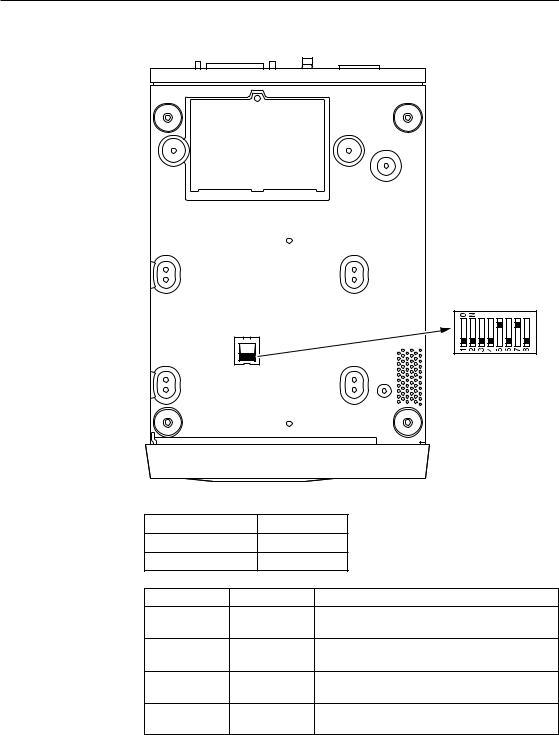
Option Switches (DIP Switch)
|
|
1. Reserved (OFF) |
|
|
2. Reserved (OFF) |
|
|
3. Reserved (OFF) |
|
|
4. Reserved (OFF) |
|
|
5. Terminator Power (ON) |
|
|
6. Reserved (OFF) |
|
|
7. DC Control-1 (ON) |
|
|
8. DC Control-2 (OFF) |
|
|
( ) . . . default setting |
Terminator Power |
Definition |
|
OFF |
No provided |
|
ON |
Provided |
|
DC Control-1 DC Control-2 |
Definition |
|
OFF |
OFF |
Compression disabled at power-on. The |
|
|
host is allowed to control compression. |
OFF |
ON |
Compression disabled at power-on. The |
|
|
host is not allowed to control compression. |
ON |
OFF |
Compression enabled at power-on. The |
|
|
host is allowed to control compression. |
ON |
ON |
Compression enabled at power-on. The |
|
|
host is not allowed to control compression. |
Chapter 2 Preparation 15

 Chapter 3 Operation
This section describes users of the LCD (display), and procedures for loading cartridges in the magazine, using the drive unit, and handing magazines and cartridges.
Menu Settings and Checks
Certain machine settings can be made and viewed from the LCD Menu screen, including model and firmware version display and the current SCSI ID setting of the machine.
The Menu screen is controlled by the following procedure.
Note:
The magazine should be removed before switching display to the Menu screen. When the magazine is inserted into the autoloader, the Menu screen can only be displayed when the LCD shows “Ready”. To change the language setting, the magazine must be removed.
1Press and hold the SELECT button for 5 seconds. The display changes to the Menu screen.
z Version
Auto Load
Unload
Contrast
Orientation
Language
Menu Screen
2Press the SELECT button to move the cursor (z) among the menu items.
3Press ENTER to display the setting screen for the selected item.
4Choose the desired setting for the selected item as described in the following descriptions of the choices for each setting screen.
If no further action takes place for 10 seconds, the menu is exited and display returns to normal.
16 Chapter 3 Operation

Version Display
When Version is selected in the Menu screen, the following screen appears, where you can confirm the autoloader model, SCSI ID, firmware version and serial number.
TSL-11000 SCSI ID # 5 Ver. 0000 S/NLXXXXXXXX S/NDXXXXXXXX
Model Name of this Machine
SCSI ID Number
Firmware Version
Loader Serial Number
Embedded Drive Serial Number
Version Screen
1Note the displayed information.
2Press the EJECT button.
The display returns to the Menu screen.
Auto Load Selection
When Auto Load is selected in the Menu screen, the following screen appears. From this screen you can select whether a cartridge automatically loads into the DDS drive when a magazine is placed in the auto loader.
Auto Load
z OFF
ON
Auto Load Selection Screen
1Press the SELECT button, if necessary, to move the cursor (z) to the desired setting.
When ON is selected and a magazine is placed in the autoloader, the first cartridge automatically loads into the DDS drive after the cartridges have been checked. When OFF is selected, autoloading does not occur.
You can press the EJECT button to cancel any change to the selection and return to the Menu screen.
2Press the ENTER button to accept the selection and return to the Menu screen.
Chapter 3 Operation 17

Unload Selection
When Unload is selected in in the Menu screen, the following screen appears. From this screen you can select what happens when the last cartridge finishes processing: that is, whether it is simply unloaded from the DDS drive, or if the first cartridge is subsequently reloaded and processing continued automatically (in a continuous loop).
Unload
Contiunuous
z OFF
ON
Unload Selection Screen
1Press the SELECT button, if necessary, to move the cursor (z) to the desired setting.
When OFF is selected, the first cartridge does not automatically reload into the DDS drive after the last cartridge finishes. When ON is selected, the first cartridge automatically reloads.
You can press the EJECT button to cancel any change to the selection and return to the Menu screen.
2Press the ENTER button to accept the selection and return to the Menu screen.
Contrast Adjustment
When Contrast is selected in the Menu screen, the following screen appears.
You can adjust the display contrast from this screen.
Contrast
Adjustment
ppppπππ
Contrast Adjustment Screen
1Press the SELECT button, as necessary, to adjust the contrast.
You can press the EJECT button to cancel any change to the selection and return to the Menu screen.
2Press the ENTER button.
The contrast setting is accepted and the display returns to the Menu screen.
18 Chapter 3 Operation

Orientation Setting
When Orientation is selected in the Menu screen, the following screen appears, where you can select the orientation of the display to match your viewing angle.
Orientation
z Horizontal
R-side down L-side down
Orientation Screen
1Press the SELECT button, as necessary, to move the cursor (z) to the desired setting.
The orientation of the displayed characters corresponds with the current selection.
You can press the EJECT button to cancel any change to the selection and return to the Menu screen.
2Press the Enter button.
Accepts the selected display orientation and returns to the Menu screen. The display orientation switches when exiting the Menu screen.
Note
When making settings with the Menu screen, the display is always oriented so that the top of the display corresponds with the top of the unit.
Chapter 3 Operation 19

Language Selection
Note
To change the language setting, remove the magazine from the unit. The language setting cannot be changed while the magazine is inserted.
When Language is selected in the Menu screen, the following screen appears, where you can select the language of the displayed messages.
Language
z English
French
German
Spanish
Language Screen
1Press the SELECT button, as necessary, to move the cursor (z) to the desired setting.
You can press the EJECT button to cancel any change to the selection and return to the Menu screen.
2Press the ENTER button to accept the selection and return to the Menu screen.
Note
The Menu screen itself is always displayed in English.
20 Chapter 3 Operation
Loading Cartridges into the Magazine
Setting 8 cartridges into the magazine
It is recommended that all 8 cartridges be used as recording media. Depending on the application software, a cleaning cartridge can be set in place of one of the data cartridges. The sequence in which cartridges are set into the magazine determines the numbers by which they are managed as indicated in the figure below.
Numbers of data cartridges inside the magazine (Setting 8 cartridges into the magazine)
Setting 7 cartridges into the magazine
Numbers of data cartridges inside the magazine
(Setting 7 cartridges into the magazine)
Note:
If cartridges are not loaded in one of the arrangements indicated in the figures, the magazine will eject. The cleaning cartridge can only be used in the 8 position.
Setting 1 cartridge into the magazine
Either a data cartridge or cleaning cartridge can be loaded into the 8 position.
Numbers of data cartridges inside the magazine
(Setting 1 cartridge into the magazine)
Note:
If no cartridge is loaded into the position indicated above, the magazine is ejected.
Chapter 3 Operation 21
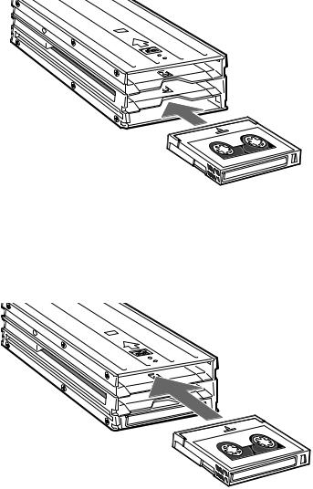
Load data cartridges into the magazine as follows.
1First, load data cartridges into the bottom shelf of the magazine as shown in the figure below.
Load cartridge 3 first, followed by cartridges 2 and 1 (in that order).
Loading data cartridges into the bottom magazine shelf
2Load data cartridges into the top shelf of the magazine as shown in the figure below.
Load cartridge number 4 first, followed by cartridges 5, 6, and 7 (in that order).
Loading data cartridges into the top magazine shelf
22 Chapter 3 Operation

3A data cartridge should be set into the middle shelf of the magazine. Depending on the application software, a cleaning cartridge can be inserted instead of a data cartridge.
Inserting a cartridge into the middle magazine shelf
Removing Cartridges from the Magazine
Remove cartridges from the magazine as follows.
1Pressing down on the magazine stopper, place your finger in the hole at the rear of the magazine and push data cartridges toward the front of the magazine.
Pushing cartridges from the rear of the magazine
Chapter 3 Operation 23
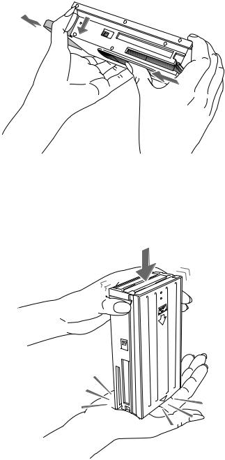
2Position your thumb in the slot in the bottom of the magazine and continue sliding the cartridges toward the front of the magazine.
Pushing cartridges through the bottom of the magazine
3Repeat steps 1 and 2 to remove five of the cartridges.
4Turn the magazine so that the open end faces up and tap it gently against your hand or a soft object. This makes cartridges move from the top shelf to the bottom shelf.
Moving top shelf cartridges to the bottom shelf
24 Chapter 3 Operation
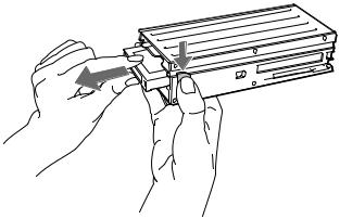
5Repeat steps 1 and 2 to remove the cartridges from the bottom shelf.
6Finally, remove the cartridge from the cleaning cartridge position in the middle shelf.
Removing catridge from middle shelf.
Chapter 3 Operation 25
How to Use the DDS Auto Loader Unit
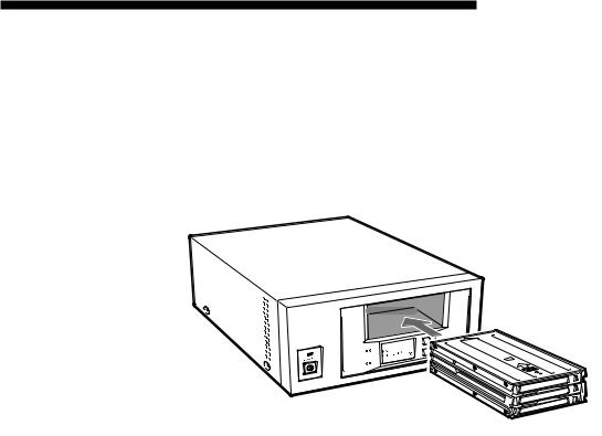
1Press the POWER switch on the front panel.
The power turns on and the POWER indicator lights.
Self-testing starts: the BUSY indicator and the TAPE indicator should each light briefly.
2Ensure that the BUSY and TAPE indicators are off, then insert the magazine.
SELECT
EJECT
ENTER
 BUSY
BUSY
 TAPE
TAPE
Inserting the magazine
When the magazine is loaded, the following actions occur:
• After “Magazine Loading” appears, checking of the magazine starts.
• If the magazine is write-protected, the write-protect indicator ( ) appears.
•All cartridges are checked in order.
•As each cartridge is checked, its number blinks.
Note
When Autoload is set to ON by the Menu screen and a magazine is inserted, the first cartridge is loaded into the DDS drive automatically after the cartridges within the magazine have been checked.
3When all cartridge numbers display on the LCD, a cartridge to be loaded into the DDS drive may be selected by computer software or by the SELECT or ENTER buttons on the machine. When a cartridge is loaded into the DDS drive, the TAPE indicator lights.
4Data may be read or written on the tape using computer software. While reading or writing, the BUSY indicator lights.
26 Chapter 3 Operation

Data Cartridge Selection
You can select data cartridges loaded into the magazine as necessary by using the software on your computer.
Data cartridges can be selected with the SELECT and ENTER buttons on this machine, by the following procedure.
1Press the SELECT button to display a cartridge number on the LCD, and press it repeatedly to change the selected data cartridge number.
2When the desired cartridge number is selected, press the ENTER button. The cartridge currently in the DDS drive is unloaded, and the cartridge selected above is loaded into the drive.
Cautions:
•After inserting the magazine, about 90 seconds are needed for checking the cartridgesin the magazine. During that time, the SELECT button is disabled. The SELECT button is also disabled when “Ready” is not displayed.
•When Autoload is set to ON by the Menu screen and a magazine is inserted, the first cartridge is loaded into the DDS drive automatically after the cartridges within the magazine have been checked.
•The SELECT and ENTER buttons have no effect if pressed while the BUSY indicator is flashing.
Chapter 3 Operation 27
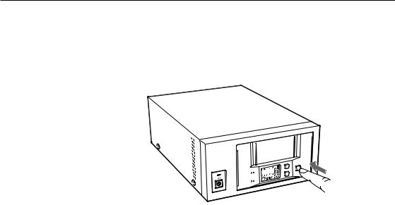
Ejecting the Magazine
Press the EJECT button.
“Ejecting Magazine” appears, and after the cartridge unloads from the DDS drive to the magazine, the magazine automatically ejects.
As much as two minutes may be required to eject a magazine.
SELECT
EJECT
ENTER
 BUSY
BUSY
 TAPE
TAPE
Ejecting the magazine
Caution:
The EJECT button has no effect if pressed while the BUSY indicator is flashing.
28 Chapter 3 Operation

 Chapter 4 Care and Maintenance
Taking Care of the Autoloader Unit
Safety Considerations
■ Power
•Be sure to use only 100-120/200-240 V AC.
•Avoid plugging into the same outlet as high-current equipment like copiers or shredders.
■Power Cable Precautions
•Do not crush the cable or place heavy items on it. If the cable insulation appears worn or broken, do not use the cable.
•Always unplug the cable by holding the plug: never pull the cable itself, as it will break.
•If the unit is not being used for a long time, unplug the cable from the outlet.
•Once a year, please clean the power plug.
■Other
•When the magazine is not installed, avoid putting fingers in the magazine insertion slot.
Avoiding Damage
■ Avoid shock and vibration
Intense shock, such as from dropping the unit, will damage it.
■ Environmental considerations
Do not store or use the unit in locations subject to:
•high humidity
•excessive dust
•high temperature
•intense vibration
•direct sunlight
•sudden changes in temperature
■ Proper ventilation
To avoid overheating, install the unit where it will have free air circulation around the case, and do not cover it during operation. The unit can malfunction if the internal temperature rises too high.
Chapter 4 Care and Maintenance 29

■ Avoid sudden changes in temperature
If the unit is moved from a cool place to a warm place, or if the room temperature suddenly rises, moisture may condense inside the case. After a sudden change in temperature, wait at least one hour before turning the unit on. If the unit is turned on with condensation inside, and a cartridge is installed, the drive or the tape can be damaged.
■ Abnormal occurrences
If the drive behaves abnormally, or if it begins to smell or smoke, immediately unplug it from the wall outlet and contact your supplier for assistance.
Other precautions
■ Electromagnetic interference (EMI)
The drive utilizes high frequency electronic circuits which could cause noise in radio or television receivers, or audio equipment. If this occurs, try increasing the distance between the devices.
■ Cabinet cleaning
Wipe the cabinet with a soft dry cloth. For heavy dirt, wipe with a soft cloth moistened with a gentle liquid soap, then wipe again with a soft dry cloth. Do not use alcohol, paint thinner, bug sprays or other volatile solvents, as they can damage the finish.
■ Installation
Make sure that the place of installation has a level surface; otherwise, the magazine may fall out when it is ejected.
30 Chapter 4 Care and Maintenance
 Loading...