


 Loading...
2-638-113-31 (1)
Color Video Printer
Instructions for Use
UP-55MD
© 2005 Sony Corporation
Owner's Record
The model and serial numbers are located at the rear. Record these numbers in the space provided below. Refer to these numbers whenever you call upon your Sony dealer regarding this product.
Model No. ____________________
Serial No. ____________________
WARNING
To prevent fire or shock hazard, do not expose the unit to rain or moisture.
To avoid electrical shock, do not open the cabinet. Refer servicing to qualified personnel only.
THIS APPARATUS MUST BE EARTHED.
For the customers in Canada
This unit has been certified according to Standard CSA C22.2 No.601.1.
For the customers in the U.S.A and Canada
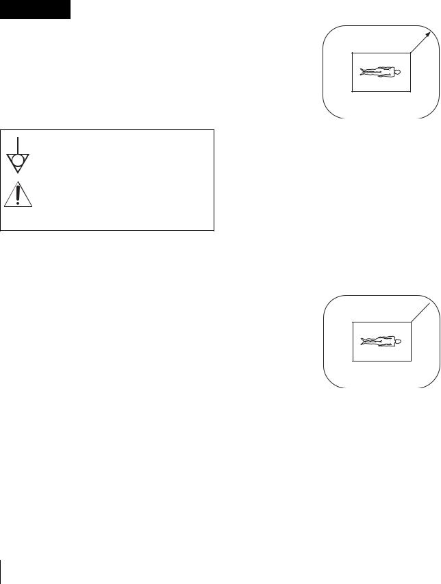
Model UP-55MD is Non-Patient Equipment.
This unit can not be used in the vicinity of patients.
* Patient Vicinity
.83m |
||
R1 |
(6 |
feet) |
|
|
|
This symbol indicates the equipotential terminal which brings the various parts of a system to the same potential.
This symbol is intended to alert the user to the presence of important operating and maintenance (servicing) instructions in the literature accompanying the appliance.
For the customers in the U.S.A.
This equipment has been tested and found to comply with the limits for a Class A digital device, pursuant to Part 15 of the FCC Rules. These limits are designed to provide reasonable protection against harmful interference when the equipment is operated in a commercial environment. This equipment generates, uses, and can radiate radio frequency energy and, if not installed and used in accordance with the instruction manual, may cause harmful interference to radio communications. Operation of this equipment in a residential area is likely to cause harmful interference in which case the user will be required to correct the interference at his own expense.
You are cautioned that any changes or modifications not expressly approved in this manual could void your authority to operate this equipment.
The shielded interface cable recommended in this manual must be used with this equipment in order to comply with the limits for a digital device pursuant to Subpart B of Part 15 of FCC Rules.
Important safeguards/notices for use in the medical environments
1.All the equipments connected to this unit shall be certified according to Standard IEC60601-1, IEC60950, IEC60065 or other IEC/ISO Standards applicable to the equipments.
2.When this unit is used together with other equipment in the patient area*, the equipment shall be either powered by an isolation transformer or connected via an additional protective earth terminal to system ground unless it is certified according to Standard IEC60601-1.
*Patient Area
.5m  R1
R1
3.The leakage current could increase when connected to other equipment.
4.This equipment generates, uses, and can radiate frequency energy. If it is not installed and used in accordance with the instruction manual, it may cause interference to other equipment. If this unit causes interference (which can be determined by unplugging the power cord from the unit), try these measures: Relocate the unit with respect to the susceptible equipment. Plug this unit and the susceptible equipment into different branch circuit.
2

Consult your dealer. (According to standard EN60601-1-2 and CISPR11, Class B, Group 1)
Caution
When you dispose of the unit or accessories, you must obey the law in the relative area or country and the regulation in the relative hospital.
Warning on power connection
Use a proper power cord for your local power supply.
1.Use the approved Power Cord (3-core mains lead) / Appliance Connector / Plug with earthing-contacts that conforms to the safety regulations of each country if applicable.
2.Use the Power Cord (3-core mains lead) / Appliance Connector /Plug conforming to the proper ratings (Voltage, Ampere).
Warning on power connection for medical use
Please use the following power supply cord.
With connectors (plug or female) and cord types other than those indicated in this table, use the power supply cord that is approved for use in your area.
|
United States |
Canada |
|
|
|
Plug Type |
HOSPITAL GRADE* |
HOSPITAL GRADE* |
|
|
|
Female end |
E62405, E35708 |
LR53182, LL022442, |
|
|
LL088408 |
|
|
|
Cord type |
E159216, E35496 |
LL112007-1, LL20262, |
|
Min.Type SJT |
LL32121, LL84494 |
|
Min.18 AWG |
Min.Type SJT |
|
|
Min.18AWG |
|
|
|
Minimum cord set |
10A/125V |
10A/125V |
rating |
|
|
Safety approval |
UL Listed |
CSA |
|
|
|
*Note: Grounding reliability can only be achieved when the equipment is connected to an equivalent receptacle marked ‘Hospital Only’ or ‘Hospital Grade’.
Caution
Danger of explosion if battery is incorrectly replaced. Replace only with the same or equivalent type recommended by the manufacture.
Dispose of used batteries according to the manufacture’s instructions.
3

Table of Contents
Introduction
System Overview ................................................... |
5 |
Location and Function of Parts and Controls .... |
5 |
Front Panel ......................................................... |
5 |
Rear Panel .......................................................... |
7 |
Monitor Display ................................................. |
7 |
Preparation
Supplied Accessories ............................................. |
9 |
Connections ............................................................ |
9 |
Connecting Video Equipment .......................... |
10 |
Connecting the Video Monitor ......................... |
11 |
Making Connections to Enable Remote Control . |
|
12 |
|
Before Printing .................................................... |
12 |
Loading an Ink Ribbon Cartridge .................... |
12 |
Inserting the Paper Tray/Loading Paper ........... |
15 |
Selecting the Input Signal ................................ |
17 |
Setting Date and Time ...................................... |
18 |
Adjustment
Functions That Can be Set on Menus ................ |
45 |
Menu Tree ............................................................. |
46 |
Basic Menu Operations ....................................... |
47 |
Adjusting the Color and Picture Quality ........... |
50 |
Compensating for the Input Signals ................. |
50 |
Matching the Video Monitor Color to the Printer |
|
Color ............................................................... |
50 |
Adjusting the Printout Color ............................. |
51 |
When a Black Frame or Lines Show up on the |
|
Printouts .......................................................... |
54 |
Fitting the Printout to the Paper ........................ |
55 |
Adjusting the Color Balance ............................. |
55 |
Making Various Settings ..................................... |
58 |
Assigning Functions to the Remote Control Unit 58
Adjusting the Brightness of the Printer Window
Display ............................................................ |
60 |
Selecting Whether the Operation and Error Tones |
|
Sound .............................................................. |
60 |
Setting the Baud Rate ....................................... |
60 |
Displaying the Remaining Amount of the Ink |
|
Ribbon ............................................................ |
60 |
Registering a User Set ...................................... |
60 |
Operation |
|
Making Full-Size Image Printouts ..................... |
20 |
Making Printouts with the Desired User Set |
|
Number ........................................................... |
22 |
Making Multiple Copies of Identical Printouts 24 |
|
Capturing Another Image While Printing ........ |
26 |
Making Variations of Printouts .......................... |
27 |
Selecting the Memory Mode ............................ |
27 |
Selecting a Memory Page ................................. |
28 |
Making a Printout of Multiple Different Reduced |
|
Images ................................................................... |
29 |
Making Printouts With Date or a Caption ....... |
34 |
Making Printouts With a Caption ..................... |
34 |
Entering a Caption ........................................... |
35 |
Making Printouts with a Date .......................... |
38 |
Deleting Images Stored in Memory ................... |
39 |
Setting the Function of the CLEAR Button ..... |
39 |
Deleting Images Stored in Memory ................. |
39 |
Erasing the Screen Display on the Video Monitor 41
Storing Image Data on a USB Flash Memory |
|
Device .................................................................... |
42 |
Storing Image Data on a USB Flash Memory |
|
Device ............................................................ |
42 |
Selecting the Printer Operation When the USB |
|
Flash Memory Device Becomes Full ............. |
43 |
Making Printouts with File Names .................. |
44 |
Miscellaneous |
|
Precaution ............................................................. |
62 |
Safety ................................................................ |
62 |
Installation ........................................................ |
62 |
Before Transporting the Printer ........................ |
62 |
Cleaning ............................................................ |
62 |
Ink Ribbon and Paper ......................................... |
63 |
Specifications ........................................................ |
63 |
Error/Warning Messages .................................... |
65 |
Error Messages ................................................. |
65 |
Warning Messages ............................................ |
66 |
Troubleshooting .................................................... |
67 |
If Damage is Suspected .................................... |
67 |
If the Paper Jams ................................................. |
68 |
Index ...................................................................... |
71 |
4
Introduction
System Overview
The UP-55MD is a color video printer that quickly and easily reproduces images from video equipment such as a VTR.
The UP-55MD has the following features:
•High picture quality and high print resolution The printer allows you to print out high resolution
images in full color (with 256 shades per color, a total of more than 16,700,000 colors in all) in high resolution print mode (approximately 379 dpi).
•Menu settings to meet your printer’s specifications By changing the menu settings for the printer, you can make various types of printouts. You can also add a caption to the printout. You can carry out ordinary printer operations using the buttons on your printer and you can set up the printer interactively by choosing settings from displayed menus.
•USB host port
The printer is equipped with a USB host port so that you can store image data captured in the printer in the USB flash memory in the JPEG (Joint Photographic Experts Group) format. You can see the image data captured using a personal computer.
Location and Function
of Parts and Controls
For details, refer to the pages given in parentheses.
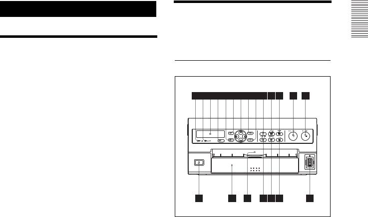
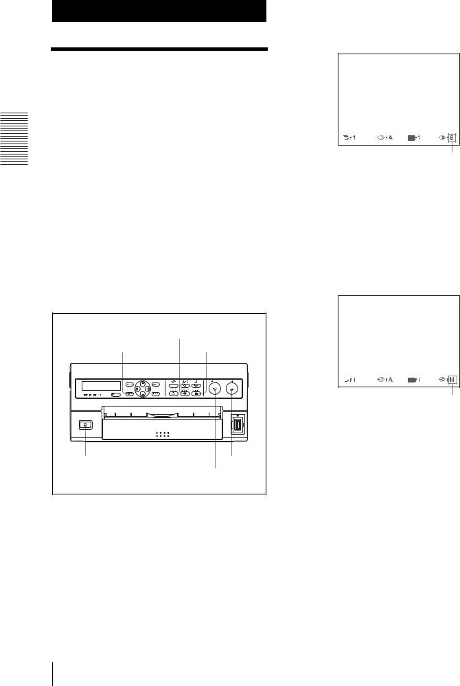
Front Panel
APRINT indicator
Lights while the printer is printing.
BALARM indicator (65)
Lights in orange when the ink ribbon or paper is exhausted, the paper jams, or another problem occurs.
CPrinter window display
Displays messages that also appear along the bottom edge of the monitor screen. The printer window display has a narrower display range and shows only a limited number of characters. Also displays the menu screen line at which the cursor is positioned. If an error occurs, a corresponding error message is displayed.
The contrast of the printer window display can be adjusted on the SYSTEM SETUP menu. (“Adjusting the Brightness of the Printer Window Display” on page 60.)
DRemote sensor (12)
Aim the head of the remote control unit toward this sensor.
EDISPLAY button (22, 41)
When the regular screen is displayed, pressing this button toggles the screen display of messages such as Q1, A, etc., on and off regardless of the setting of
Introduction
System Overview / Location and Function of Parts and Controls |
5 |
|
|

Introduction
the DISPLAY item in the OUTPUT SETUP menu. The setting of DISPLAY in the OUTPUT SETUP menu changes linked with the press of this button. When the menu is displayed, pressing this button temporarily clears the menu display. While this button is held down, the menu display disappears.
FMENU button
Press this button to display or clear the menus.
GF/f/G/g (Cursor) keys
Use to select a desired item from the menu. Also, these keys are used to position the cursor (green pointer) on the regular screen when capturing multiple reduced images.
HCLEAR button (39, 40)
Press this button to clear the images captured in the memory pages. Which images can be cleared with the CLEAR button depends on the setting made with the FUNCTION SETUP menu.
When the clear function of this button is set to OFF, the buzzer sounds if you press the CLEAR button.
IEXEC button
Press this button to execute the values set with the COLOR ADJUST menu or to load a user set in the PRINTER SETUP menu and to register the user set in the SYSTEM SETUP menu. Also, this button is used to enter the characters of a caption in the CAPTION menu.
JLOAD USER button
Press this button to recall a registered user set.
K MULTI PICTURE button (29)
Press this button to select the desired printout type on the regular screen. When you press this button, the currently selected printout type is displayed for a few seconds. Each time you press this button, the type is switched in the following sequence: 1, 2, 4, 8, 1.... The setting of MULTI PIX on the LAYOUT SETUP menu changes linked with the press of this button.
L PRINT QTY (quantity) button (24)
Press this button to set the number of copies on the regular screen. You can set any number up to 10. When you press this button, the currently selected number is displayed for a few seconds. The setting of PRINT QTY on the PRINTER SETUP menu changes linked with the press of this button. You can change the number of copies currently printed even when the printer is printing.
M CAPTURE button
Press this button to capture an image in a memory page.
N PRINT button
Press this button to make a printout.
OUSB host port
Insert the USB flash memory into this port.
Note
Be sure not to insert a USB flash memory manufactured by other manufactures other than Sony Corporation.
PSTOP button (21)
Press this button to stop continuous printing. The printer stops printing after finishing the printing item currently being printed.
Q SOURCE/MEMORY button
Press this button to select which signal is to be output to the monitor.
The memory image and source image are toggled each time you press this button.
R MEMORY PAGE button (26, 29, 40)
Press to select the memory page.
SPaper output slot
Printed pages (printouts) are ejected here. Depending on the curled condition of printouts, the printer may stop printing and display the message “REMOVE PRINTS.” In such a case, remove the printouts accumulated on the paper tray. The printer will start to print the remaining copies automatically.
TPaper tray (9, 15)
Load paper into this tray.
U! POWER switch
Press this switch to turn the printer on or off.
6 Location and Function of Parts and Controls
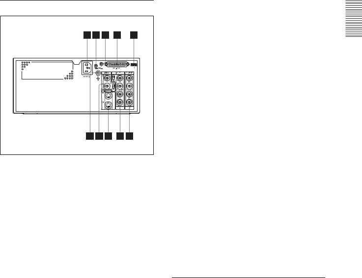
Rear Panel
A- AC IN connector (10, 11, 12)
Use a proper power cord for your local power supply (not supplied).
Refer to “Warning on power connection” on page 3 and “Warning on power connection for medical use” on page 3.
BREMOTE 1 connector (special mini jack) (12)
Used to connect an RM-5500 Remote Control Unit (not supplied) to be used as a wired remote control unit.
C REMOTE 2 connector (stereo mini jack) (12)
Used to connect a RM-91 Remote Control Unit (not supplied).
DRS-232C connector (12)
Used to connect a computer to control the printer. For details, contact your nearest Sony dealer.
EDip switches
Used to set the video signal system to select either NTSC or PAL video system.
When the dip switch 1 is set to the lower position, the NTSC video system is selected.
When the dip switch 1 is set to the upper position, the PAL video system is selected.
FOUTPUT (RGB/YCbCr/SYNC) connectors (10)
Used to connect the video equipment with RGB/ YCbCr input connectors.
GINPUT (RGB/YCbCr/SYNC) connectors/75Ω termination ON/OFF switch (10)
INPUT connector: Used to connect the video equipment with RGB/YCbCr output connectors.
75Ω ON/OFF switch: Normally set this switch to ON. Set it to OFF if the input signal should drop when you connect additional equipment to the video equipment.
HS-VIDEO IN/S-VIDEO OUT (S-video signal input/S-video signal output) connectors (10, 11)
S-VIDEO IN connector: Used to connect to the video equipment with Y/C separated output connector.
S-VIDEO OUT connector: Used to connect to the video equipment with Y/C separated INPUT connector.
IVIDEO IN/VIDEO OUT connectors (Composite
video signal input/composite video signal output)//75Ω termination ON/OFF switch (10,
11)
VIDEO IN connector: Used to connect to the video equipment with a composite video signal output connector.
VIDEO OUT connector: Used to connect to the video equipment with a composite video signal
input connector.
75Ω ON/OFF switch: Normally set this switch to ON. Set it to OFF if the input signal should drop when you connect additional equipment to the video equipment.
J Equipotential ground terminal connector
Used to connect to the equipotential plug to bring the various parts of a system to the same potential. Refer to “Important safeguards/notices for use in the medical environments” on page 2.
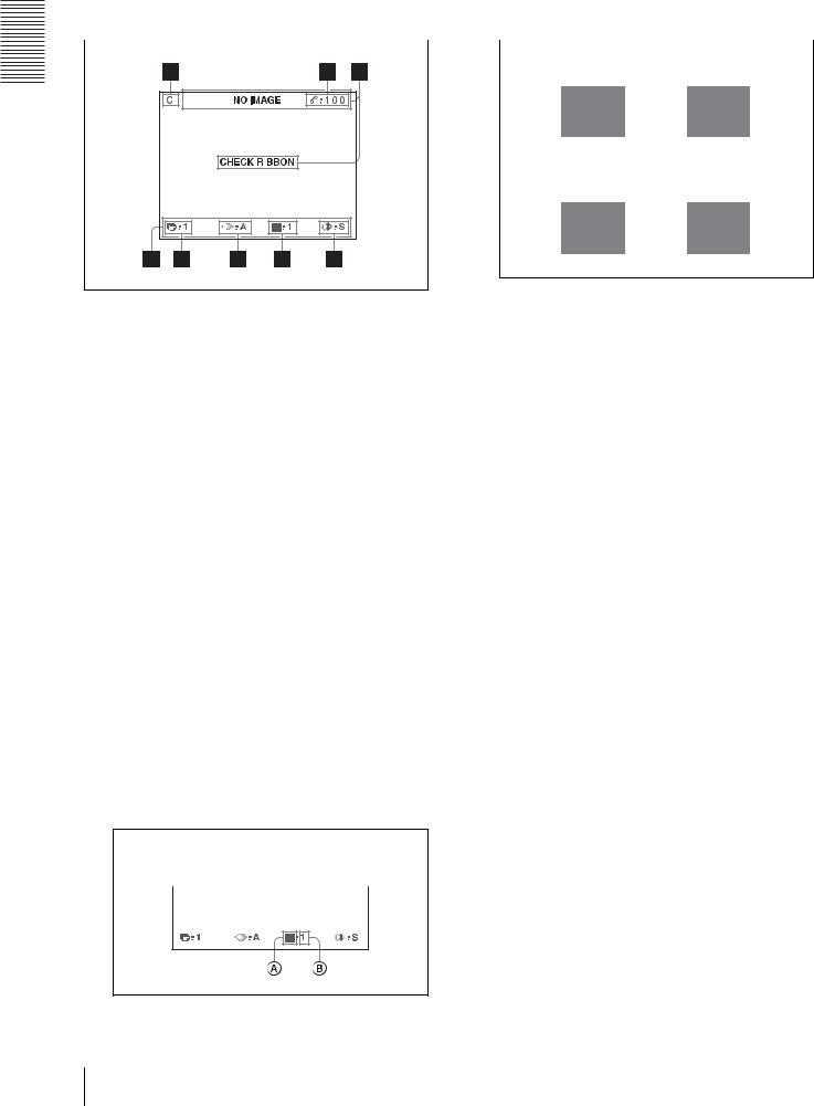
Monitor Display
When the printer is connected to the video monitor and you first turn on the printer, the following regular screen message appears.
When the MENU button is pressed, the menu screen displayed.
Introduction
Location and Function of Parts and Controls |
7 |
|
|
For detailed information on the menu screen, see “Menu |
|
A Type of printout |
|
Tree” on page 46. |
|
Indicates the type of printout. |
|
|
|
|
|
|
|
Full-size image |
Two reduced |
|
|
images |
|
|
|
|
|
Introduction
|
Four reduced |
Eight reduced |
|
||
|
images |
images |
AC (caption)/F (file name) display section
C is displayed when the printer is set to print a caption.
F is displayed when the printer is set to print a file name.
BRemaining amount of ink ribbon display section
Displays the remaining amount of ribbon (indicates the number of printouts that can still be made with the ribbon).
CMessage display section
Messages are displayed.
Usually messages are displayed on the top line of the screen.
Urgent messages are displayed on the center of the screen.
DS or M (image type) display section
Indicates the type of image being displayed on the monitor screen.
S (Source): The image from the input signal source is displayed on the screen.
M (Memory): The image captured in memory is displayed on the screen.
EPrinter operation mode display section
Indicates the printer operation mode (type of printouts such as multiple reduced images).
Position of the cursor:
1st position of four reduced images
When SEPARATE (image with white borders) is set to ON on the LAYOUT SETUP menu, the borders are displayed on the screen.
BPosition of the cursor
Indicates the position where the cursor is currently placed and where an image will be captured.
FMemory page display section
Indicates the currently selected memory page. While the image in the memory page is being printed, the memory page indication blinks. The memory page whose memory image is queued to be printed blinks.
GQ (print quantity) display
Indicates the number of copies to be printed. This item blinks while the printer is busy.
HPrinter setting status display section
The corresponding currently selected status is displayed when either MULTI PICTURE or PRINT QTY button is pressed.
8 Location and Function of Parts and Controls
Preparation
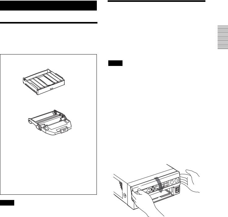
Supplied Accessories
The printer is packed together with the following accessories. Check that nothing is missing from your package.
Paper tray (1)
Ink ribbon holder (1)
Warranty card (1) (for the customers in the U.S.A and Canada only)
CD-ROM (1)
Before Using this Printer (1) Instructions for Use (1)
Notes
•Retain the original carton and packing materials in case you have to transport the unit in the future.
•Remove the ink ribbon cartridge and paper tray when transporting the printer.
Connections
To enable printing, video equipment to act as an input signal source, and a video monitor to display images or menus must be connected.
The following diagrams illustrate how to make the input, output and remote control connections. Use this as a guide when connecting the cables required to transmit signals to and from the equipment to be used for printing.
Notes
•Turn off the power of each device before attempting to make any connections.
•Connect the AC power cord last.
Inserting a battery
You can add a printing date on a printout below the image. Also, when a captured image is stored in a USB flash memory device, a time stamp indicating the time the image was captured is recorded. To make a printout with the correct time and record a correct time stamp, a properly charged lithium battery must be installed in the printer beforehand.
For detailed information on how to set the date and time, see “Setting Date and Time” on page 18 and for the information on how to make a printout with a printing date, see “Making Printouts with a Date” on page 38.
1 Open the front door.
Preparation
Supplied Accessories / Connections |
9 |
|
|
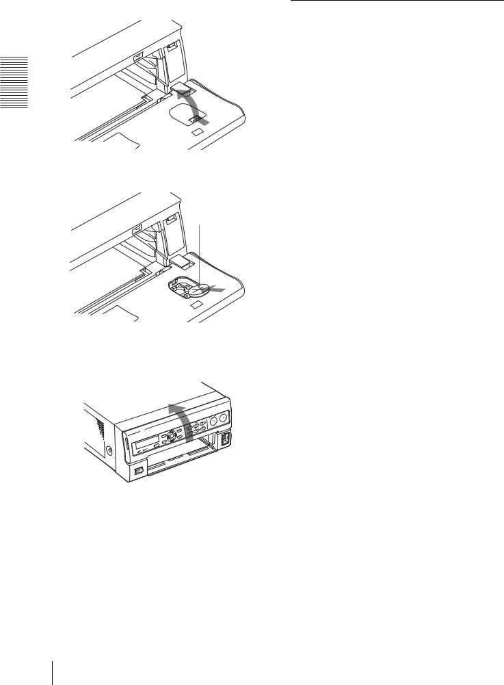
2 Remove the battery cover.
Preparation
3 Install the lithium battery.
Face the + side up.
4 Replace the battery cover as it was, and close the front panel.
Notes on the lithium battery
•A button type lithium battery (CR2025) (not supplied) is required. Do not use batteries other than the CR2025.
•Keep the lithium battery out of the reach of children.
•Should the battery be swallowed, immediately consult a doctor.
Connecting Video Equipment
Connect the video equipment providing the video images to be printed.
Connect the video equipment which will be used in actual printing, using the following diagram as a guide. Before connecting the video equipment, see “Important safeguards/notices for use in the medical environments” on page 2.
10 Connections

to wall outlet |
75-ohm |
|||
termination |
||||
|
|
switch a) |
||
|
|
|
|
|
AC power cord |
|
|
|
|
(not supplied) |
|
|
|
|
|
|
|
|
|
to AC IN
Dip switch b)
to VIDEO |
|
|
INPUT |
|
|
Connecting |
to S |
to RGB/YCbCr/ |
VIDEO |
SYNC c) INPUT |
|
cable (with |
INPUT |
|
DIN 4-pin |
|
|
connectors) |
|
|
75-ohm |
|
75-ohm |
|
coaxial cable |
|
coaxial cable |
|
with BNC |
with BNC |
to S VIDEO |
connectors |
connectors |
output |
|
|
|
|
|
connector |
|
|
|
to RGB/ |
|
|
YCbCr output |
to composite |
|
connectors |
video output connector
Video equipment
a)Two kinds of 75 Ω termination switches are provided, one is for the RGB/YCbCr input and the other is for the composite video signal. Normally set this switch to ON. Set it to OFF if the level of the input signal drops because the signal is divided to additional video equipment other than the printer.
b)Set the dip switches to match your video signal system. Set the switch 1 to the lower position to set the video signal system to NTSC. Set the switch 1 to upper position to set the video signal system to PAL. To switch the video signal system, turn the power off once, then change the setting. Then, turn the power on again. If you change the setting with the power on, this mode will not be switched.
c)When YCbCr signal is input, it is not necessary to connect to the SYNC connector.r.
Connecting the Video Monitor
Connect a video monitor to view captured images and to check those to be printed. Connect a suitable video
monitor which will be used in actual printing, using the following diagram as a guide.
to wall outlet
AC power cord (not supplied)
to AC IN
Dip switch a)
to VIDEO  OUTPUT
|
|
|
|
|
|
|
|
|
|
|
|
|
|
|
|
|
|
|
|
|
|
|
|
|
|
|
|
Connecting |
|
|
|
|
|
|
to S VIDEO |
|
|
to RGB/YCbCr/ |
|||||||||||||||||
|
|
|
|
|
|
||||||||||||||||||||||
cable (with |
|
|
|
|
OUTPUT |
|
|
SYNC OUTPUT b) |
|||||||||||||||||||
DIN 4-pin |
|
|
|
|
|
|
|
|
|
|
|
|
|
|
|
|
|
|
|
|
|
|
|
||||
connectors) |
|
|
|
|
|
|
|
|
|
|
|
|
|
|
|
|
|
|
|
|
|
|
|||||
75-ohm |
|
|
|
|
|
|
|
|
|
|
|
|
|
|
|
|
|
|
|
|
|
|
75-ohm |
||||
|
|
|
|
|
|
|
|
|
|
|
|
|
|
|
|
|
|
|
|
coaxial cable |
|||||||
coaxial cable |
|
|
|
|
to S VIDEO |
|
|
|
|
|
|
|
with BNC |
||||||||||||||
|
|
|
|
|
|
|
|
|
|
||||||||||||||||||
with BNC |
|
|
|
input |
|
|
|
|
|
|
|
connectors |
|||||||||||||||
connectors |
|
|
|
connector |
|
|
|
|
|
|
|
|
|
||||||||||||||
|
|
|
|
|
|
|
|
|
|
|
|
|
|
|
|
|
|
|
|
|
|
|
|
|
|
|
to RGB/YCbCr |
|
|
|
|
|
|
|
|
|
|
|
|
|
|
|
|
|
|
|
|
|
|
|
|
|
|
|
|
|
|
|
|
|
|
|
|
|
|
|
|
|
|
|
|
|
|
|
|
|
|
|
|
|
|
|
|
|
|
|
|
|
|
|
|
|
|
|
|
|
|
|
|
|
|
|
|
|
|
|
|
|
|
|
|
|
|
|
|
|
|
|
|
|
|
|
|
|
|
|
|
|
|
|
|
|
|
|
|
|
|
|
input |
to composite |
|
|
|
|
|
|
|
|
|
|
|
|
|
|
|
|
|
|
|
|
|||||||
|
|
|
|
|
|
|
|
|
|
|
|
|
|
|
|
|
|
|
|
connectors c) |
|||||||
video input |
|
|
|
|
|
|
|
|
|
|
|
|
|
|
|
|
|
|
|
|
|
||||||
connector
Video monitor
a)Set the dip switches to match your video signal system Set the switch 1 to the lower position to set the video signal system to NTSC. Set the switch 1 to upper position to set the video signal system to PAL. To switch the video signal system, turn the power off once, then change the setting. If you change the setting with the power on, this mode will not be switched.
b)When connecting the video monitor only to the RGB/ YCbCr/SYNC OUTPUT connector without connecting to SYNC connector, set OUTPUT SYNC in the OUTPUT SETUP menu to ON.
c)When YCbCr signal is output, it is not necessary to connect to the SYNC connector.
Preparation
Connections 11

Preparation
Making Connections to Enable Remote Control
The printer can be controlled remotely by connecting an RM-5500 Remote Control Unit (not supplied), an RM91 Remote Control Unit (not supplied), or a personal computer.
Computer a)
to wall outlet
AC power
cord (not  RS-232C cable
  supplied)
to AC IN |
to RS-232C |
to REMOTE 1 |
to REMOTE 2 |
Remote control connecting cable (supplied with  the RM-5500)
RM-5500 b) (not supplied) RM-91 (not supplied)
a)When connecting a personal computer, select the appropriate baud rate from the SYSTEM SETUP menu. (See “Setting the Baud Rate” on page 60.)
b)You can also use the remote control unit as a wireless unit. In such a case, aim the head of the remote control unit at the remote sensor on the printer. With fresh batteries, the range of the remote control unit is about 3 meters.
Before Printing
Before printing, but after mounting the paper tray on the printer and making the necessary connections (see “Connections” on page 9), perform the following as preparation.
•Loading an ink ribbon (See below.)
•Loading paper (See page 15.)
•Selecting the input signal (See page 17.)
•Setting the date and time (See page 18.)
Notes
•Use the ink ribbon and paper contained in the same package as a pair. Before attempting to load an ink ribbon or paper, make sure that the combination of the ink ribbon and paper is compatible.
•When either an ink ribbon or paper has been exhausted, replace both the ink ribbon and paper at the same time.
•Use only ink ribbon and paper designed for use with this printer. Failing to do so is likely to result in malfunctions. (See“Ink Ribbon and Paper” on page 63.)
Loading an Ink Ribbon Cartridge
To make printouts, an ink ribbon cartridge (an ink ribbon holder which has been loaded with an ink ribbon) and paper must be loaded. This section describes how to set the ink ribbon into the supplied ink ribbon holder and to load the ink ribbon cartridge in the printer.
When you use the printer for the first time, start the operation to load the ink ribbon cartridge from step 4.
Notes
•When you use the printer for the first time, the thermal head may be out of position. Before attempting to load the ink ribbon cartridge, turn on the power under the condition where the front door is closed so that the thermal head is placed at the correct position.
•If a blank sheet of paper is ejected, and the message “RIBBON END” appears, the ink ribbon has been exhausted. Replace the paper together with the ink ribbon. Do not reuse the ejected blank paper.
•Once an ink ribbon has been completely used up, replace it. An ink ribbon is not reusable.
•Do not rewind the ink ribbon for reuse.
•Do not touch the ink ribbon or place it in a dusty location. Finger prints or dust on the ink ribbon will result in imperfect printing or malfunction of the head.
12 Before Printing
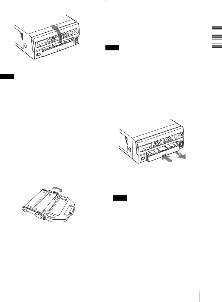
1 Open the front door by pulling the front door toward you.
2 Remove the ink ribbon cartridge.
If you can not remove the ink ribbon cartridge
The thermal head may be out of position.
In such a case, close the front door, and turn the power off, then back on again. After a while, start the operation from step 1 again.
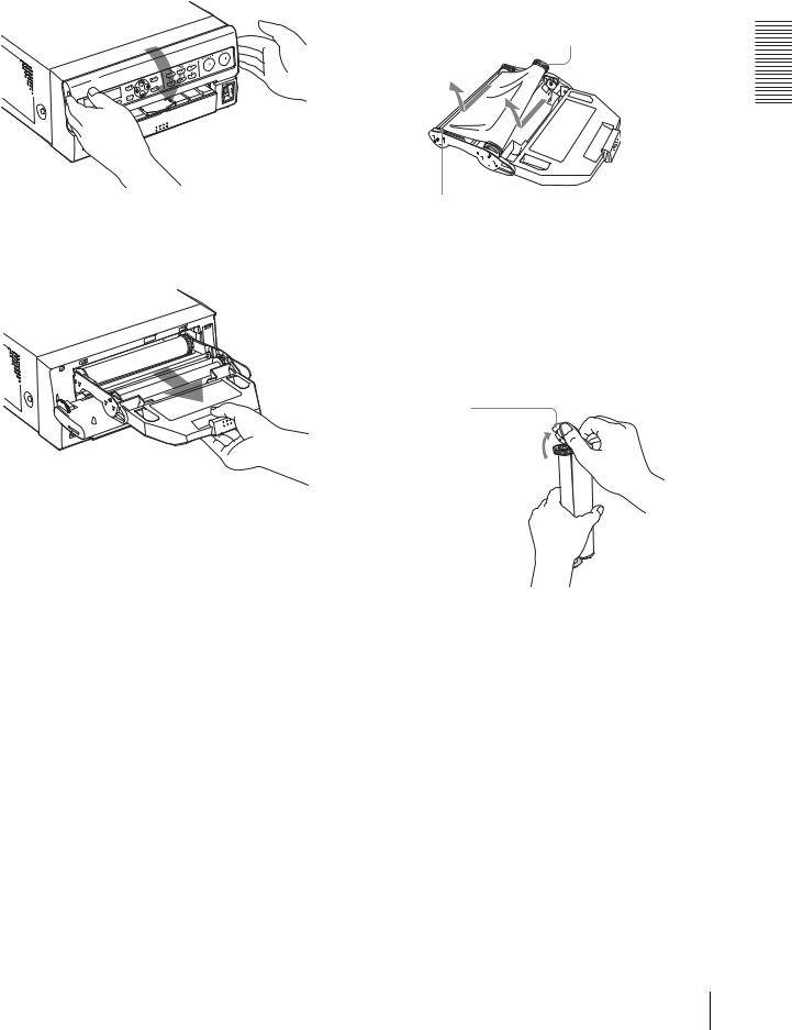
3 Detach the spent ink ribbon from the ink ribbon holder.
Pushing the ink ribbon spool that takes up the ink ribbon in the direction of the arrow, remove the spool from the side with the gray gear.
Preparation
Pushing the ink ribbon spool that sends the ink ribbon in the direction of the arrow, remove the spool from the side with the white gear.
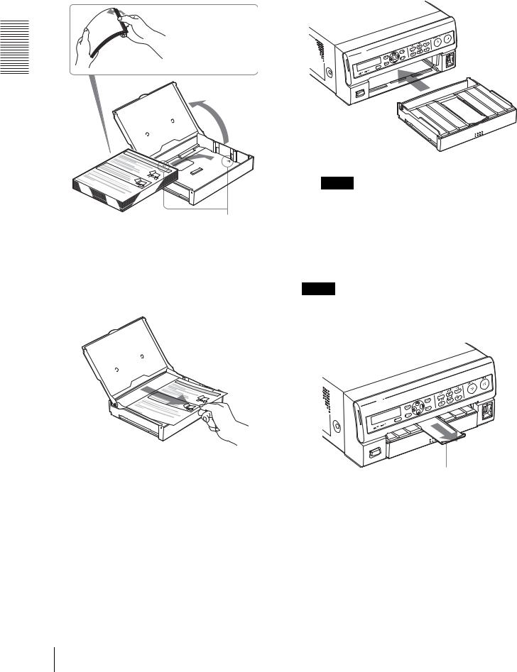
4 Load the new ink ribbon into the ink ribbon holder.
1Holding the ink ribbon firmly, remove the gear cover.
Gear cover
To avoid dropping the ink ribbon, make sure that you hold it firmly.
Before Printing 13
Preparation
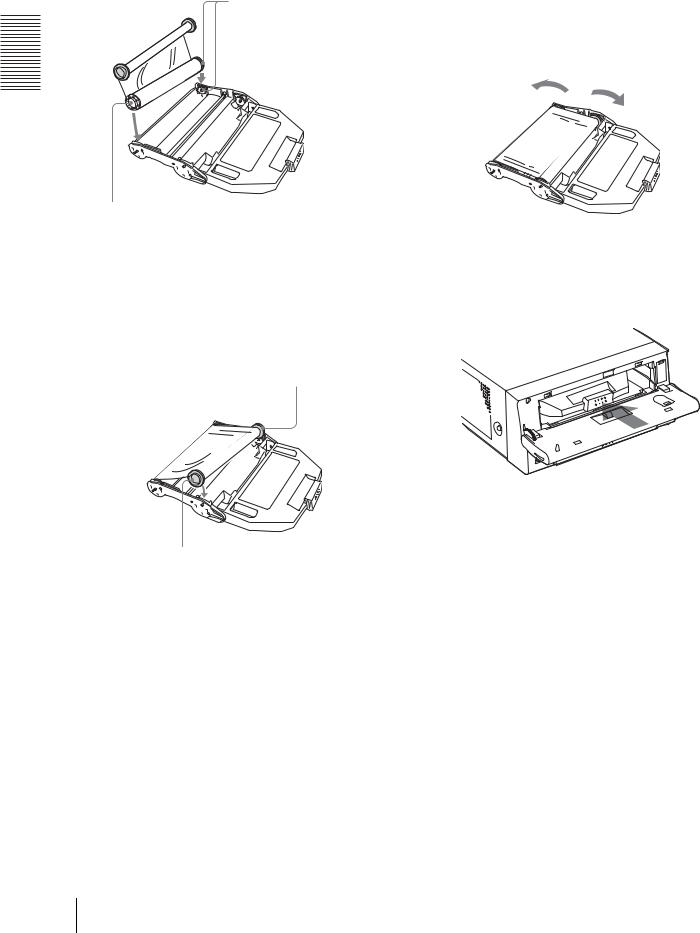
2Place the ink ribbon with the white gear as illustrated.
1 Press the white gear of the ink ribbon.
Match the color of the gear of the ink ribbon spool and the color of the ink ribbon holder.
2Press the other side of the ink ribbon until you hear it click into place.
If the ribbon is left slack, it may be damaged when the ink ribbon cartridge is inserted into the printer.
Turn the gears in the direction of the arrows until any slack is eliminated and the magenta section of the ink ribbon appears.
5 Insert the ink ribbon cartridge until it stops.
3Place the ink ribbon with the gray gear in the same way as explained in step 2.
1Press the gray gear of the ink ribbon.
2Press the other side of the ink ribbon until you hear it click into place.
4Eliminate any slack in the ribbon by turning the gears.
If the ink ribbon cartridge cannot be inserted
In such a case, close the front door, and turn the power off, then back on again. Insert the ink ribbon cartridge again.
14 Before Printing
6 Close the front door.
Notes
When handling the ink ribbon:
•Do not rewind the ink ribbon for reuse.
•When handling the ink ribbon, be careful not to touch the surface of the ink ribbon. Dust or finger prints are likely to cause unsatisfactory printing or malfunction of the head.
When storing ink ribbon:
•Avoid placing the ink ribbon in a location subject to:
–high temperatures
–high humidity
–excessive dust
–direct sunlight
•Store a partially used ink ribbon in its original packaging.
If your ink ribbon should tear
Repair the tear with transparent tape. There should be no problem with using the remaining portion of the ribbon.
Transparent tape
Turn the gray gear of the spool that takes up the ink ribbon in the direction of the arrow to remove any slack until the transparent tape cannot be seen.
Inserting the Paper Tray/Loading
Paper
To load paper in the paper tray and insert the paper tray into the printer, follow the procedure below. Be careful not to touch the printing surface of the paper.
When you use the printer for the first time, start the operation to insert the paper tray from step 2.
Notes
•Use only the paper recommended. Failing to do so is likely to result in malfunctions such as paper jams. (See “Ink Ribbon and Paper” on page 63.)
•When a blank sheet of paper is ejected and the message “RIBBON END” appears, the ink ribbon has been exhausted. Replace the paper together with the ink ribbon. Do not use the ejected blank paper.
•Be careful when removing and inserting the paper tray. If you are not careful, you may drop the printer.
1 Push the paper tray to remove it.
2 Place the paper in the paper tray so that the printing surface faces up with the protection sheet on top.
Notes
•Do not add only the paper. When the paper supply has been exhausted, replace both the ink ribbon and paper at the same time. If you add paper while printing, this may cause the paper jam.
•When handling the paper, do not touch the printing surface. Dust or finger prints are likely to cause unsatisfactory printing or malfunction of the head. Grasp the paper by the printing surface protection sheet.
•Load the paper so that it lays flat in the paper tray. If the paper is curled, it will overflow from the paper tray and paper may not be fed properly. Be sure to riffle the paper along with the
Preparation
Before Printing 15
protection sheets before placing the paper in the paper tray.
4 Slide the paper tray back into the printer until it clicks into place.
Riffle the paper with the protection sheet.
Preparation
Place paper with the arrow pointing in the same direction as in the tray.
3 Remove the protection sheet placed on the top of the paper.
Note
If you cannot insert the paper tray completely, check whether any paper is left inside the printer. If you find a left sheet, slowly pull it straight out.
How to use the paper eject stopper
To keep ejected printouts on the paper tray, pull the paper eject stopper on the paper tray out until it clicks.
Note
Do not leave more than 10 sheets of ejected printouts. Doing so may cause a paper jam.
Pull the paper eject stopper on the paper tray out until it clicks.
When storing the paper
•Avoid storing the paper in a location subject to:
–high temperatures
–high humidity
–excessive dust
–direct sunlight
•Use the original package for storing unused paper.
16 Before Printing

|
4 Select the desired input signal by pressing the G or |
|
Selecting the Input Signal |
||
g button. |
||
|
||
Before printing, select the appropriate input signal (the |
|
|
input connector to which the signal to be printed is being |
Highlight the desired input signal in green |
|
input) VIDEO, S VIDEO, or COMP. |
by pressing the G or g button. The selected |
|
|
input signal turns green and is spelled out. |
2, 5 |
2, 4, 5 |
|
. |
1 |
2, 3 |
|
|
|
|
|
|
|
|
|
|
|
|
|
|
|
|
|
|
|
|
|
|
|
|
|
|
|
|
|
|
|
|
|
|
|
|
|
|
|
|
|
|
|
|
|
|
|
|
|
|
|
|
|
|
|
|
|
|
|
|
|
|
|
|
|
|
|
|
|
|
|
|
|
|
|
|
|
|
|
|
|
|
|
|
|
|
|
|
|
|
|
|
|
|
|
|
|
|
|
|
|
|
|
|
|
|
|
|
|
|
|
|
|
|
|
|
|
|
|
|
|
|
|
|
|
|
|
|
|
|
|
|
|
|
|
|
|
|
|
|
|
|
|
|
|
|
|
|
|
|
|
|
|
|
|
|
|
|
|
|
|
|
|
|
|
|
|
|
|
|
|
|
|
|
|
|
|
|
|
|
|
|
|
|
|
|
|
|
|
|
|
|
|
|
|
Source signal of the |
Video monitor and |
|||||||||||
image to be printed |
printer window display |
|||||||||||
|
|
|
|
|
|
(the selected input |
||||||
|
|
|
|
|
|
signal is spelled out) |
||||||
|
|
|
|
|
|
|
|
|
|
|
|
|
Signal from video |
V tVIDEO |
|||||||||||
equipment connected to the |
|
|
|
|
|
|
|
|||||
VIDEO IN connector |
|
|
|
|
|
|
|
|||||
1 Turn on the video monitor and the printer.
2 Press the MENU button and display the INPUT SETUP menu by pressing the F, f, G or g button.
Highlight IN in green by pressing the F, f, G or g button, then the INPUT SETUP menu appears.
Signal from video |
SV t S-VIDEO |
equipment connected to the |
|
S VIDEO IN connector |
|
|
|
Signal from video |
Ct COMP. |
equipment connected to the |
|
RGB/YCbCr/SYNC |
|
INPUT connectors |
|
|
|
Preparation
When you select COMP.
When you use the RGB/YCbCr INPUT connectors to input the image data, select the appropriate type of the input signal.
1 Select INPUT FORM by pressing the f button.
Highlight INPUT FORM in green by pressing the f button.
3 Select INPUT SEL by pressing the F or f button.
Highlight INPUT SEL in green by pressing the F or f button.
Before Printing 17

2 Select the type of the input signal.
Highlight the desired input signal in green by pressing the G or g button.
Preparation
Signal input to the RGB/ |
Select |
YCbCr/SYNC INPUT |
|
connectors |
|
|
|
RGB input signal |
RGB |
|
|
YCbCr input signal |
YCbCr |
|
|
The format of the component signal output from the RGB/YCbCr/SYNC OUTPUT connector depends on the component signal selected here.
5 Press the MENU button. The normal screen appears.
Setting Date and Time
The printer adds a time stamp when the captured image data is stored on an external USB flash memory device. Also, you can make a printout with the date when the image was printed. To put the correct time stamp or to print the correct printing date on printouts, you have to set the correct date and time.
Note
Be sure to install a lithium battery before attempting to set date and time. If do not do so, the date and time can not be set correctly.
|
2, 7 |
2, 4 |
1 |
2, 3 |
6 |
|
|
4, 5 |
1 Turn on the video monitor and the printer.
2 Press the MENU button and display the LAYOUT SETUP menu by pressing the F, f, G or g button.
Switch LAY to green by pressing the F, f, G or g button, then the LAYOUT SETUP menu appears.
3 Select CLOCK ADJUST by pressing the F or f button.
Highlight CLOCK ADJUST in green by pressing the F or f button.
18 Before Printing
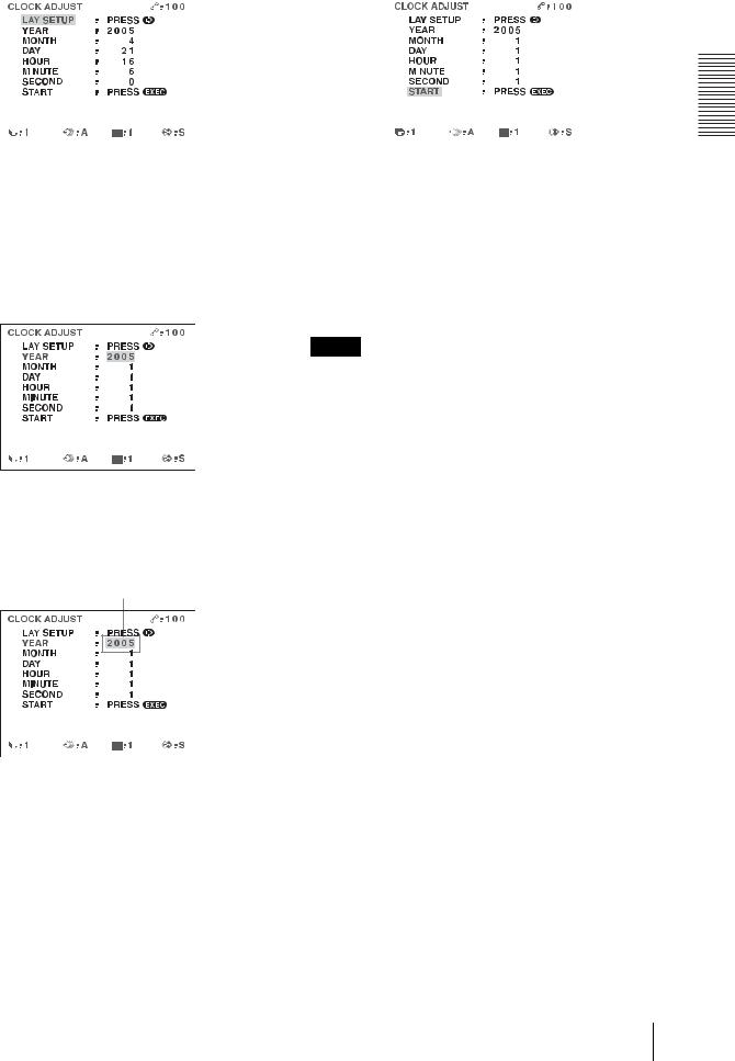
CLOCK ADJUST menu appears. |
5 Highlight START by pressing the f button. |
||||||||
|
|
|
|
|
|
|
|
|
|
|
|
|
|
|
|
|
|
|
|
|
|
|
|
|
|
|
|
|
|
|
|
|
|
|
|
|
|
|
|
|
|
|
|
|
|
|
|
|
|
|
|
|
|
|
|
|
|
|
|
|
|
|
|
|
|
|
|
|
|
4 Set the year, month, day, hour, minute and second respectively.
To set year
1Press the f button.
The YEAR column is highlighted in green.
2Display the desired year by pressing the G or g button.
Press the G or g button until the desired year appears.
3 Highlight MONTH by pressing the f button.
4 Set MONTH, by repeating step 2.
5Set from DAY to SECOND, by repeating steps 1 and 2.
HOUR is a 24-hour display.
Switch START to green.
6 Press the EXEC button. The internal clock starts.
7 Press the MENU button. The normal screen appears.
Note
If a lithium battery has not been inserted beforehand, the time advances while the printer is powered. When it is turned off, the internal clock stops. When it is turned on again, the internal clock starts from the time when the image data was stored in the USB flash memory last time.
For detailed information on how to install a battery, see “Inserting a battery” on page 9.
Preparation
Before Printing 19
2 Start the video source to display the source image Operation on the video monitor.
This operation is done using the controls of the video equipment acting as the source.
Operation
Making Full-Size Image
Printouts
This section explains how to make a full-size image printout. The operations described here constitute the basic procedure for making a printout.
Before making a full-size image printout
•All connections should have already been made. (See page 9.)
•Ensure that the appropriate ink ribbon/paper set is being used and that they are correctly loaded. (See pages 12, 15 and 63.)
•Select the input signal to be used to make a printout. (See page 17.)
•Set the printer to capture one full-size image into memory. (See page 30.)
•Select the appropriate memory page. (See page 28.)
•Confirm the printout color quality (using, for example, the LOAD COLOR number). (See page 51.)
•Insert a lithium battery and set the date and time to progress the built-in clock correctly.
SOURCE MEMORY button |
|
DISPLAY button |
STOP button |
1 |
4 |
|
3 |
1 Turn on the video monitor and the printer.
Shows that an image from the source equipment is currently displayed on the screen.
3 Press the CAPTURE button at the instant the image you want to print appears on the screen.
The image is captured into memory. The memory image is displayed on the screen. Which image appears after this, the source image or the memory image, depends on the setting made with the FUNCTION SETUP facility of the printer. (See page 31.)
Shows that an image captured in memory is displayed on the monitor.
If the captured image is blurred
A quickly moving image may be blurred when captured. Should this occur, change the memory mode setting to FIELD, then print it again. Although the blur should be eliminated, the ultimate print quality will be slightly degraded. Select the FIELD mode on the LAYOUT SETUP menu. (See “Selecting the memory mode” on page 28.)
20 Making Full-Size Image Printouts
Note
Usually, it is recommended that you make printouts in FRAME mode.
You can confirm the memory mode setting on the bottom part of the video monitor screen.
When FRAME mode is selected:
The printing time depends on the print speed settings.
On the video monitor, Q display blinks in the color which is being printed.
The color changes as follows during printing: Start t yellow t magenta t cyan t finish
On the printer window display, the color indication changes as the color printing precedes:
Start t YELLOW t MAGENTA t CYAN t finish
When FIELD mode is selected:
To change the image captured in memory
1To display the source image when the memory image is displayed on the screen, press the SOURCE/MEMORY button.
2Press the CAPTURE button at the instant the image you want to print appears.
The previous image is replaced with the new one.
4 Press the PRINT button.
The printout pops out on the paper tray.
Notes
•Do not turn off the power during printing.
If you do so, paper may not be ejected and may jam in the printer.
•Do not open the front door or not to remove the paper tray during printing. Doing so may cause the paper jamming because paper is not ejected correctly.
•Do not leave more than 10 sheets of printouts on the paper tray. Doing so may cause a paper jam. Even if fewer than 10 sheets of printouts have been accumulated on the paper tray, the printer may stop printing for various reasons and the message “REMOVE PRINTS” appears. In such a case, remove printouts accumulated on the paper tray. The printer will start to print automatically.
•You can not change the printer application mode or settings using the WINDOW SETUP menu during printing.
To stop printing
•When you make one printout, you can not stop printing midway. Wait until a printout pops out on the paper tray.
•When you make multiple copies, press the STOP button. (For detailed information on setting the print quantity, see “Making Multiple Copies of Identical Printouts” on page 24.) The printer stops printing when the page currently printing is completed. Also, any printing job queued are cancelled.
Operation
Making Full-Size Image Printouts |
21 |
|
|
Operation
If the printer does not print
While an error message is displayed on the video monitor screen and printer window display.
Proceed as described in “Error/Warning Messages” on page 65.
To make a printout at high speed
You can select the speed using the PRN SPEED item on the PRINTER SETUP menu.
When you want to |
PRN SPEED |
Make a printout at normal speed. |
NORMAL |
|
|
Make a printout at high speed. |
HIGH |
|
|
For detailed information on how to operate the menu, see “Basic Menu Operations” on page 47.
When you want to see an image that is hidden below a screen message
You can erase screen messages (such as Q1, A and so on) from the video monitor screen by pressing the DISPLAY button. The screen message disappears. To display a screen message, press the DISPLAY button again. (See “Erasing the Screen Display on the Video Monitor” on page 41.) You can also erase the information about ink ribbon and paper. (See “Displaying the Remaining Amount of the Ink Ribbon” on page 60.)
If a black line appears on the printout
Sometimes, a black line appears on the printout, although it does not appear on the video monitor. This black line can be eliminated from the printout. (See “When a Black Frame or Lines Show up on the Printouts” on page 54.)
If the color quality of the printouts is not satisfactory
You can obtain satisfactory color quality of the printouts by compensating for the input signal and/or adjusting the color quality of the printouts. (See “Compensating for the Input Signals” on page 50 and “Adjusting the Printout Color” on page 51.)
When you load a new ink ribbon and paper, the color balance may change due to differences caused by the new pair of ink ribbon and paper in the new printing pack. It is recommended that you adjust the color balance each time you load a new ink ribbon and paper. (“Adjusting the Color Balance” on page 55.)
When storing your printouts:
•Avoid storing the printout in a location subject to high temperatures, high humidity, excessive dust or direct sunlight.
•Do not stick tape on a printout. Also, avoid leaving a plastic eraser on a printout or placing a printout in contact with materials which contain plasticizer (under a desk mat, for example).
•Do not allow alcohol or other volatile organic solvents to come into contact with the printouts.
Making Printouts with the Desired User Set Number
You can register all the printer settings as a user settings. The printer allows you to register three sets of settings as User Set 1, 2 and 3. (See “Registering a User Set” on page 60.) By selecting a desired user set number, the printer functions according to the corresponding settings. You can change a part of the selected user settings and make printouts.
The following two methods are available to select the desired user set number:
•Using the LOAD USER button
•Using the menu
To select the desired user set number by using the LOAD USER button
2 |
3 1, 2 |
4 |
5 |
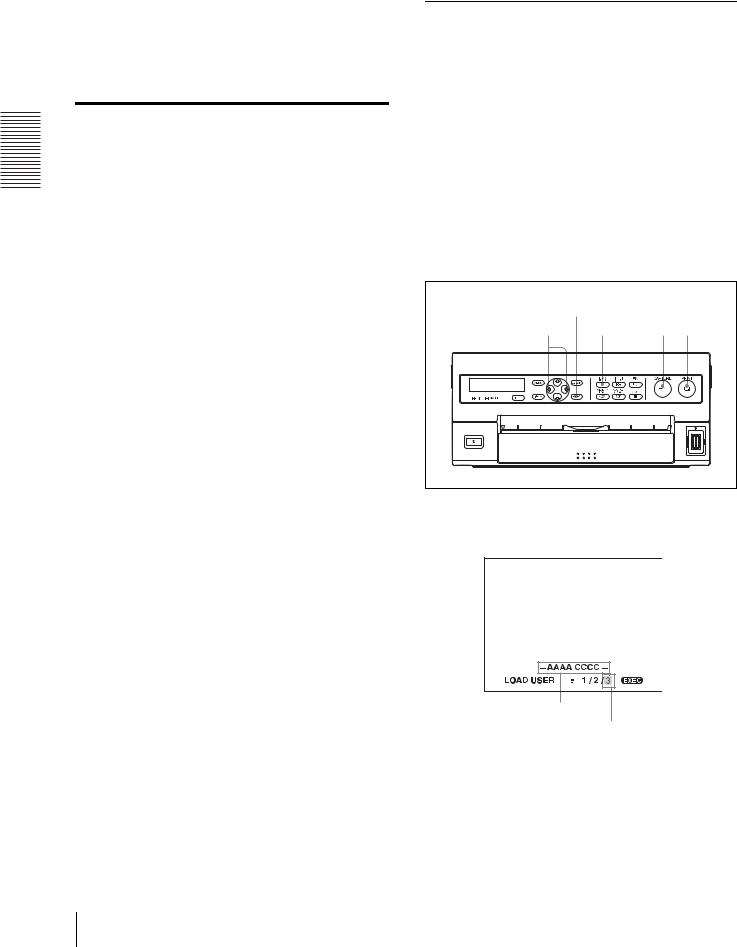
1 Press the LOAD USER button.
The currently selected user set number appears.
User name of the
currently selected
user set number Currently selected user set number is lit in
green.
22 Making Full-Size Image Printouts
Loading...