


4-092-824-07 (1)
Trinitron®
Color Video Monitor
2 _____________________________________ JP
Instructions for Use page 20 _______________________________ GB
Mode d’emploi page 34 ___________________________________ FR
Gebrauchsanweisung seite 50 _____________________________ DE
Manual de instrucciones página 66 __________________________ ES
Instruzioni per l’uso pagina 82 ______________________________ IT
______________________________________ CS

PVM-9L3
PVM-9L2
PVM-14L2
PVM-20L2
© 2002 Sony Corporation
4 6
7
5 1
a
b
c
|
|
|
|
|
|
|
|
|
|
|
|
|
2
|
|
....7 |
|
.............................................. |
7 |
.............................................. |
7 |
........................................... |
7 |
....................................... |
7 |
................................................................................................ |
7 |
................................................................................................ |
8 |
................................... |
8 |
....................................................................... |
9 |
............................................................ |
9 |
......................................................... |
10 |
.............................................. |
11 |
............................................................... |
12 |
........................................................... |
13 |
............................................................. |
13 |
......................................................... |
13 |
..................................... |
13 |
...................... |
14 |
............... |
14 |
............................. |
14 |
..................................... |
15 |
.......................... |
15 |
........................................................... |
16 |
................................................... |
16 |
................................................................ |
16 |
............................................... |
16 |
..................................................................................... |
16 |
........................................................... |
i |
|
|
PVM-9L3/PVM-9L2 ................ |
|
JP
PVM-9L3 9
PVM-9L2 9
PVM-14L2 14
PVM-20L2 20 PVM14L2
A
3

|
|
|
|
|
|
|
|
|
|
|
|
|
|
|
|
|
|
|
|
|
|
||||||
|
|
|
|
|
|
|
|
|
|
|
|
||
|
|
|
|
|
|
|
|
|
|
|
|
||
|
|
|
|
|
|
|
|||||||
|
|
|
|
|
|
|
|||||||
|
|
|
|
|
|
|
|
|
|
|
|
||
|
|
|
|
|
|
|
|
|
|
|
|
||
|
|
|
|
|
|
|
|
|
|
|
DC |
||
|
|
|
|
|
|
|
|
|
|
|
|
|
|
|
|
|
|
|
|
|
|
|
|
|
|
|
|
|
|
|
|
|
|
|
|
|
|
|
|
|
|
|
|
|
|
|
|
|
|
|
|
|
|
|
|
|
|
|
|
|
|
|
|
|
|
|
|
|
|
|
|
|
|
|
|
|
|
||||||
|
|
|
|
|
|
|
|
|
|
|
|
||
|
|
|
|
|
|
|
|
|
|
|
|
||
|
|
|
|
|
|
|
|
|
|
|
|
||
|
|
|
|
|
|
|
|
|
|
|
|
||
|
|
|
|
|
|
|
|
|
|
|
|
||
|
|
|
|
|
|
|
|
|
|
|
|
||
|
|
|
|
|
|
|
|
|
|
|
|
||
|
|
|
|
|
|
|
|
|
|
|
|
||
|
|
|
|
|
|
|
|
|
|
|
|
|
|
|
|
|
|
|
|
|
|
|
|
|
|||
|
|
|
|
|
|
|
|
|
|
|
|
|
|
|
|
|
|
|
|
|
|
|
|
|
|
|
|
|
|
|
|
|
|
|
|
|
|
|
|
|
|
|
|
|
|
|
|
|
|
|
|
|
|
|
|
|
|
|
|
|
|
|
|
|
|
|
|
|
|
|
|
|
|
|
|
|
|
|
|
|
|
|
|
|
|
|
|
|
|
|
|
|
|
|
|
||
|
|
|
|
|
|
|
|
|
|
|
|
||
|
|
|
|
|
|
|
|
|
|
|
|
||
|
|
|
|
|
|
|
|
|
|
|
|
||
|
|
|
|
|
|
|
|||||||
|
|
|
|
|
|
|
|
|
|
|
|
|
|
|
|
|
|
|
|
|
|
|
|
|
|||
|
|
|
|
|
|
|
|
|
|
|
|
|
|
|
|
|
|
|
|
|
|
|
|
|
|
|
|
|
|
|
|
|
|
|
|
|
|
|
|
|
|
|
|
|
|
|
|
|
|
|
|
|
|
|
|
|
|
|
|
|
|
|
|
|
|
|
|
|
2 |
|
|
|
|
|
|
|
|
|
|
|
|
|
|
|
|
|
|
|
|
|
|
|
|
|
|
2 |
|
|
|
|
|
|
|
|
|
|
|
|
|||
|
|
|
|
|
|
|
|
|
|
|
|
|
|
|
|
|
|
|
|
|
|||||||
|
|
|
|
|
|
|
|
|
|
|
|
1 |
|
|
|
|
|
|
|
|
|
|
|
|
|
|
|
|
|
|
|
|
|
|
|
|
|
|
|
|
|
|
|
|
|
|
|
|
|
|
|
|
|
|
|
|
|
|
|
|
|
|
|
|
|
|
|
|
|
|
|
|
|
|
|
|
|
|
|
|
|
|
|
|
|
|
|
|
|
|
|
|
|
|
|
|
|
|
|
|
|
|
|
|
|
|
|
|
|
|
|
|
|
|
|
|
|
|
|
|
|
|
|
|
|
|
|
|
|
|
|
|
|
|
|
|
|
|
|
|
|
|
|
|
|
|
|
|
|
|
|
|
|
|
|
|
|
|
|
|
|
|
|
|
|
|
|
4
えることがあります。


AC/DC
10cm


真夏の、窓を閉め切った自動車内では50
2
21
の上に設置しない。


5

えることがあります。
1 1
PVM-9L3/PVM-9L2
a
b
3 #
6

DEGAUSS
DEGAUSS 9 qf DEGAUSS
5 6
1U
1) 600 PVM-14L2/PVM- 20L2
NTSC
2
NTSC PAL 2
RGB/ PVM-14L2/ PVM-20L2
RGBRGB/COMPONENT
Y/C S
Y C 2
張できます。入力拡張用オプションボードは1 2
操作パネルのEXT SYNC
1)“ ”
/ 7


は、内部的に75Ω
の調整、VTR
16 9
4 3 16 9
/
DEGAUSS
EIA 19
MB-520 PVM- 9L3/PVM-9L2 / MB-502B PVM-14L2SLR-103A PVM-20L2 EIA19
1 /
AC AC IN ACAC
AC IN
 AC
AC
AC
AC
PVM-9L3/PVM-9L2 BP-L60A/BP-L90A BP-M50/BP-M100
8
w;
qg qh qj qk ql |
||||
LINE |
LINE |
RGB/ |
OPTION OPTION |
|
A |
B |
COMPONENT |
A |
B |
|
RESET |
|
|
|
DEGAUSS BLUE |
UNDER |
16 : 9 |
EXT |
|
|
ONLY |
SCAN |
|
SYNC |
qf qd qs qa q; |
||||
a POWER!
b VOLUME
c CONTRAST
d PHASE
PAL
e CHROMA
f BRIGHT
g MENU/EXIT
h ENTER/SELECT
MENU |
CHROMA PHASE CONTRAST |
VOLUME |
POWER |
BRIGHT |
|||
E X I T |
|
|
|
SELECT |
|
|
|
– + |
MIN MAX PUR GRN MIN MAX |
MIN MAX |
|
ENTER |
|
|
|
9 87 6 5 4 3 2 1
k 16 9
16 9
l UNDERSCAN
画面サイズが約5%
m BLUE ONLY RESET
VTR
調整ができるのはNTSC
n DEGAUSS
110
i M/+ / |
|
|
|
|
|||
m/– / |
|||
DEGAUSS |
|||
|
|||
MENU/EXIT |
|||
|
|||
|
|||
|
|||
j EXT SYNC |
o LINE A |
||
|
|||
LINE A |
|||
EXT SYNC |
|||
|
|||
|
|||
|
|
||
9
p LINE B |
s OPTION B |
|
LINE B |
|
|
|
|
|
q RGB/COMPONENT |
2 OPTION |
|
AUDIO INPUT 2 |
||
(PVM-14L2/PVM-20L2 ) |
||
|
||
RGB/COMPONENT |
||
BKM-129X BKM-155DV |
||
|
||
|
||
|
||
r OPTION A |
t |
|
|
||
|
||
|
||
|
||
OPTION |
||
|
||
AUDIO INPUT 1 |
||
18 |
||
|
||
|
||
|
PVM-14L2/PVM-20L2 PVM-9L3/PVM-9L2
1
2 |
3 |
4 |
5 6 7 |
8 |
AC IN |
LINE A |
LINE B |
RGB/COMPONENT |
PARALLEL REMOTE |
OPTION AUDIO INPUT |
|
|
|
|
G/Y |
|
1 |
2 |
IN |
OUT |
IN |
OUT |
IN |
OUT |
IN |
EXT OUT |
|
VIDEO |
|
VIDEO |
|
B/PB |
|
SYNC |
IN |
OUT |
IN |
OUT |
IN |
OUT |
IN |
OUT |
|
AUDIO |
|
AUDIO |
|
R/PR |
|
AUDIO |
1
LINE A |
|
LINE B |
|
– |
+ |
EXT SYNC |
|
OPTION AUDIO INPUT |
|
AC IN |
|
2 q; 9 
|
LINE A |
|
IN |
|
OUT |
IN |
VIDEO |
OUT |
IN |
AUDIO |
OUT |
PARALLEL |
REMOTE |
LINE B
IN  VIDEO
VIDEO  OUT
OUT
IN AUDIO OUT
|
EXT SYNC |
IN |
OUT |
1 |
2 |
OPTION AUDIO INPUT
3
7
4
6
8
a |
Y/C IN/OUT 4 DIN |
|
Y/C VTR |
|
Y/C |
1 |
|
2 |
|
|
VIDEO IN/OUT BNC |
|
VTR |
|
|
|
|
b AC IN |
|
AC |
|
c LINE A
Y/C LINE A Y/C VIDEO Y/C
AUDIO IN/OUT
VTR
d LINE B
操作パネルのLINE B
10
VIDEO IN/OUT BNC
VTR
AUDIO IN/OUT
VTR
eRGB/COMPONENT PVM-14L2/ PVM-20L2
RGB Y PB PR
RGB/COMPONENT
G/Y B/PB R/PR IN/OUT BNC
RGB Y PB PRG/Y
AUDIO IN/OUT
RGBVTR
f EXT SYNC
EXT SYNC
IN/OUT BNC
IN OUT
g PARALLEL REMOTE
◆
18
h OPTION AUDIO INPUT 1 2
る場合、その音声入力に使用する入力端子です。2OPTION AUDIO INPUT 1
2 OPTION A OPTION B
i DC 12V IN XLR PVM-9L3/PVM-9L2
DC 12V
2 DC12V 4.2A
jPVM-9L3/PVM-9L2
PVM-9L3/PVM-9L2BP-L60A/BP-L90ABP-M50/BP-M100
7
ENGLISH DEUTSCH FRANÇAIS ITALIANO ESPAÑOL ENGLISH

|
|
|
|
MENU/EXIT |
|
LINE |
LINE |
RGB/ |
OPTION |
OPTION |
|
A |
B |
COMPONENT |
A |
B |
MENU |
|
|
|
|
|
E X I T |
|
RESET |
|
|
|
SELECT |
DEGAUSS |
BLUE |
UNDER |
16 : 9 |
EXT |
ENTER |
|
ONLY |
SCAN |
|
SYNC |
|
|
|
|
|||
ENTER/SELECT
M/+ m/–
1 MENU/EXITM/+ m/– USER CONFIG ENTER/SELECT
11

2
3
USER CONFIG
U S E R C O N F I G
|
|
|
|
x R G B / C O M P S E L |
|
xxxx |
|
|
|
|
C O M P L E V E L |
|
xxxxx |
|
|
|
|
|
||
|
|
|
|
|
||
|
|
|
|
N T S C S E T U P |
|
x |
|
|
|
|
F O R M A T D I S P |
|
xxxx |
|
|
|
|
L A N G U A G E |
E N G L I S H |
|
|
|
|
|
D E G A U S S D E L A Y |
x |
|
|
|
|
|
|||
|
|
|
|
|
|
|
|
|
|
|
|
|
|
|
|
1 |
|
M/+m/– LANGUAGE |
LINE |
LINE |
RGB/ |
OPTION OPTION |
|
|||||
ENTER/SELECT |
|
|||||||||
A |
B |
COMPONENT |
A |
B |
MENU |
|||||
|
|
|
|
|||||||
|
|
|
|
|
|
E X I T |
||||
U S E R C O N F I G |
|
|
|
RESET |
|
|
|
SELECT |
||
|
|
|
|
|
|
|
|
|||
R G B / C O M P S E L |
|
xxxx |
DEGAUSS BLUE |
UNDER |
16 : 9 |
EXT |
|
|||
C O M P |
L E V E L |
|
xxxxx |
ENTER |
||||||
N T S C |
S E T U P |
|
x |
|
ONLY |
SCAN |
|
SYNC |
|
|
|
|
|
|
|
|
|
||||
F O R M A T D I S P |
|
xxxx |
|
|
|
|
|
2, 3, 4 |
||
x L A N G U A G E |
E N G L I S H |
RESET |
|
|
||||||
D E G A U S S D E L A Y |
x |
|
|
|
|
|
||||
M/+m/– |
1 MENU/EXIT |
|
||||||||
ENTER/SELECT |
|
|
||||||||
|
|
|
|
|
|
|||||
|
|
|||||||||
|
|
|
|
|
|
|||||
|
|
|
|
|
|
|
|
|
||
P E @-A M K N |
x x x x x x x |
|
|
|
|
|
|
|||
|
|
|
x x x x x |
|
|
|
|
x x x x x x x x x |
||
L R Q A |
|
|
x |
|
|
|
||||
|
|
|
|
|
|
x x x x x x x x |
||||
|
|
|
x x x |
|
|
|
|
|||
|
|
|
|
|
|
|
|
x x x |
||
|
|
|
|
|
|
|
|
|||
|
|
|
x |
|
|
|
|
|
x x x x x |
|
|
|
|
|
L R Q A |
|
|
x |
|||
|
|
|
|
|
|
|
||||
|
|
|
|
|
P E @-A M K N |
x x x x x x x |
||||
MENU/EXIT
1
整」13
え」11

2 M/+m/– ENTER/SELECT
P E @-A M K N x x x x x x x x x x x x
L R Q A x x x x
x
3 M/+m/– ENTER/SELECT
M/+m/–
12
4
数値を大きくするときは、M/+m/– ENTER/SELECT
M/+m/– ENTER/ SELECT
MENU/EXIT
1
RESET
/' |
|
||
|
|
|
|
|
|
|
|
-
PE@-AMKN 0'
LRQA
1'
/
0
1
2
4
5
6
2'
2)PVM-14L2/PVM-20L2

|
|
|
|
|
|
|
|
|
|
|
|
|
|
|
|
NTSC |
|
|
|
RGB/COMP |
PVM-14L2/PVM-20L2 |
|
|
|
|
|
|
13

イトバランスの調整には測定器が必要です
D65 D93
示が青色から白色にかわり、調整できるよ うになります。
...
...
M/+ m/–D65 D93

|
|
|
|
|
|
|
|
|
|
|
|
|
|
|
|
|
|
|
/ |
|
SMPTE/EIA |
|
ENTER/SELECT |
|
|
|
MENU/EXIT |
|
|
|
|
|
|
8
|
|
|
|
|
CONTRAST PHASE |
|
CHROMA BRIGHT |
|
|
|
... |
|
|
|
... |
|
|
|
... |
|
... |
|
|
|
|
|
... |
|
|
|
|
|
|
|
... |
|
|
|
|
|
|

RGB
|
|
|
|
RGB/COMP |
RGB/COMPONENT |
PVM-14L2/PVM-
20L2 |
RGB |
|
|
|
|
|
3 |
SMPTE 100/0/100/0
|
|
|
|
BETA 7.5 100/7.5/75/7.5 |
|
|
|
|
|
BETA 0 100/0/75/0 |
|
|
|
|
|
|
|
NTSC |
NTSC |
|
|
0 7.5 |
|
|
|
|
|
7.5 |
|
|
|
|
|
|
|
|
|
|
|
|
|
|
|
|
|
10 |
|
|
|
|
|
|
|
|
|
|
|
7 |
|
|
|
|
|
ENGLISH |
|
|
DEUTSCH |
|
|
FRANÇAIS |
|
|
ITALIANO |
|
|
ESPAÑOL |
|
|
|
|
|
|
|
14
0 99
12 1 2

PARALLEL REMOTE
1 4 6 8
– –
LINE A
LINE B
RGB/COMP PVM-14L2/PVM-20L2
OPTION A
OPTION B
16:9
◆詳しくは18

マ/
BKM-150CP
|
|
|
|
|
|
|
SDTI-CP D1-SDI |
|
|
|
|
|
|
|
D1-SDI |
|
CH1 CH2 CH15 CH16 CH1 |
|
CH16 |
|
SDTI-CP |
|
CH1 CH2 CH7 CH8 CH1 |
|
CH8 |
|
OPTION AUDIO INPUT 1 2 |
|
|
|
|
|
|
|
D1-SDI |
|
VITC RP188 |
|
|
|
SDTI-CP |
|
VITC CP-TC1 CP-TC2 ES- |
|
TC1 ES-TC2 |
|
|
|
|
CP-TC1 : SMPTE 331M System Item USER DATE/TIME STAMP
CP-TC2 : SMPTE 331M System Item CREATION DATE/TIME STAMP
ES-TC1 : SMPTE 328M MPEG ES Editing Information TIME CODE1
ES-TC2 : SMPTE 328M MPEG ES Editing Information TIME CODE2
RP188 : SMPTE RP188 Time Code
VITC : SMPTE 12M VITC SMPTE 266M D-VITC
BKM-155DV
|
|
|
|
|
|
|
CH1 CH2 CH3 CH4 CH1/3 |
|
CH2/4 CH1/3 CH2/4 CH1 CH4 |
|
|
|
OPTION AUDIO INPUT 1 2 |
|
|
|
|
BKM-120D/BKM-129X
BKM-150CP BKM-155DV BKM-xxxxxA B
15

t
RGB/COMPONENT PVM-14L2/PVM-20L2 t
RGB/COMP
BKM-150CP BKM-155DV BKMxxxxx AB t BKM-xxxxx
PVM-9L3/PVM-9L2
CRT |
HR P22 |
|
(PVM-9L3) |
|
P22 |
|
(PVM-9L2) |
|
AC100 240 V 50/60 Hz |
|
|
|
58 W 0.6 0.3 A ( |
|
BKM-150CP |
|
12 V DC 4.2 A 48 W |
|
47 W 0.5 0.25 A |
|
|
|
12 V DC 3.3 A 38 W |
|
|
|
217 × 218 × 373 mm |
|
8.0 kg |
PVM-14L2 |
|
CRT |
P22 |
|
AC100 240 V 50/60 Hz |
|
|
|
85 W 0.9 0.4 A ( |
|
BKM-150CP |
|
75 W 0.8 0.35 A |
|
|
|
|
|
346 × 340 × 430 mm |
|
18.0 kg |
PVM-20L2 |
|
CRT |
P22 |
|
AC100 240 V 50/60 Hz |
|
|
|
108 W 1.1 0.5 A ( |
|
BKM-150CP |
|
98 W 1.0 0.4 A |
|
|
|
|
|
453 × 463 × 529 mm |
|
33.0 kg |
|
|
LINE A |
|
Y/C |
4 DIN 1 |
16 / /

VIDEO BNC 1 1 Vp-p 3 dB6 dB
AUDIO 1 5 dBu 47 kΩ
LINE B
VIDEO BNC 1 1 Vp-p 3 dB6 dB
AUDIO 1 5 dBu 47 kΩ
RGB/ BNC 3 (PVM- 14L2/PVM-20L2 )
RGB 0.7 Vp-p 3 dB 6 dB Sync On Green 0.3 Vp-p
0.7 Vp-p 3 dB 6 dB 75%
AUDIO 1 5 dBu 47 kΩ
BNC 1 0.3 8 Vp-p3 2
AUDIO 2
5 dBu 47 kΩ
モジュラーコネクター8 1
LINE A
Y/C 4 DIN 175 Ω
VIDEO BNC 1 75 Ω
AUDIO 1 LINE B
VIDEO BNC 1 75 Ω
AUDIO 1 RGB/
PVM-14L2/PVM-20L2 RGB
BNC 3 75 Ω
AUDIO 1
BNC 1 75 Ω
0.8 W
PVM-9L3/PVM-9L2
50 Hz 6 MHz (0 dB/ 3 dB) PVM-14L2/PVM-20L2
50 Hz 10 MHz (0 dB/ 3 dB)1)
OFF 0 dB ON 2 6 dB
CRT 6%PVM-9L3/PVM-9L2
CRT 7%PVM-14L2/PVM-20L2
|
CRT 5% |
|
PVM-9L3/PVM-9L2 |
|
H: 4% |
|
V: 4% |
|
PVM-14L2 |
|
H: 4% |
|
V: 4% |
|
PVM-20L2 |
|
H: 5% |
|
V: 5% |
|
D65 D93 |
5000 K 10000 K
PVM-9L3/PVM-9L20.4 mm0.5 mm
PVM-14L20.4 mm0.5 mm
PVM-20L20.5 mm0.7 mm
H:1.0% V: 1.0%
( ) 450TV (PVM-9L3) 250TV (PVM-9L2)
600TV (PVM-14L2/PVM-20L2)
1) RGB
17

|
|
|
|
1 |
|
|
|
|
|
|
|
8 |
|
|
|
|
|
|
|
|
|
|
|
|
|||
|
0 35 |
|
PARALLEL REMOTE |
|
|
|
|
|
|
|
|
|
|
|
|
|
|
|
|
|
|
|
|
||||
|
30 85% ( ) |
|
|
|
|
|
|
|
|
|
|
||
|
700 1060 hPa |
8 |
|
|
|
|
|
|
|
|
|
|
|
|
|
|
|
|
|
|
|
|
|
|
|
|
|
|
|
|
|
|
|||||||||
|
10 40 |
|
|
|
|||||||||
|
|
|
|
|
|
|
|
|
|
|
|
||
1 |
LINE A |
|
|
||||||||||
|
0 90% |
|
|
||||||||||
|
|
|
|
|
|
|
|
|
|
|
|
||
2 |
LINE B |
|
|
||||||||||
|
700 1060 hPa |
|
|
||||||||||
|
|
|
|
|
|
|
|
|
|
|
|
||
3 |
ON/OFF |
|
|
||||||||||
|
|
|
|
||||||||||
|
|
|
|
|
|
|
|
|
|
|
|
|
|
|
|
4 |
|
|
|
||||||||
|
|
|
|
|
|
|
|
|
|
|
|
|
|
|
5 |
GND |
|
|
|||||||||
|
|
|
|
||||||||||
AC (1) |
|
|
|
|
|
|
|
|
|
|
|
|
|
6 |
ON/OFF |
|
|
||||||||||
AC (1) |
|
|
|
|
|
|
|
|
|
|
|
|
|
7 |
16:9 |
|
|
||||||||||
(1) |
|
|
|
|
|
|
|
|
|
|
|
|
|
|
8 |
|
|
|
|||||||||
(1) |
|
|
|
|
|
|
|
|
|
|
|
|
|
|
|
|
|||||||||||
|
|
|
|||||||||||
JIS C 61000-3-2 |
|
|
|
|
|
|
|
|
|
|
|
|
|
|
|
|
|
|
|
||||||||
|
|
5 |
|||||||||||
|
|
|
|
|
|
|
|
|
|
|
|
|
|
|
|
|
|
|
|
|
|
|
|
|
|
||
18

19

Owner’s Record
The model and serial numbers are located at the rear. Record these numbers in the spaces provided below. Refer to these numbers whenever you call upon your Sony dealer regarding this product.
Model No. ____________________
Serial No. ____________________
WARNING
To prevent fire or shock hazard, do not expose the unit to rain or moisture.
Dangerously high voltage are present inside the unit.
Do not open the cabinet. Refer servicing to qualified personnel only.
In the event of a malfunction or when maintenance is necessary, consult an authorized Sony dealer.
For the customers in the U.S.A.
This equipment has been tested and found to comply with the limits for a Class A digital device, pursuant to Part 15 of the FCC Rules. These limits are designed to provide reasonable protection against harmful interference when the equipment is operated in a commercial environment.
This equipment generates, uses, and can radiate radio frequency energy and, if not installed and used in accordance with the instruction manual, may cause harmful interference to radio communications. Operation of this equipment in a residential area is likely to cause harmful interference in which case the user will be required to correct the interference at his own expense.
You are cautioned that any changes or modifications not expressly approved in this manual could void your authority to operate this equipment.
For the customers in Canada
This Class A digital apparatus complies with Canadian ICES-003.
Pour les utilisateurs au Canada
Cet appareil numérique de la classe A est conforme à la norme NMB-003 du Canada.
For the customers in Europe
This product with the CE marking complies with both the EMC Directive (89/336/EEC) and the Low Voltage Directive (73/23/EEC) issued by the Commission of the European Community.
Compliance with these directives implies conformity to the following European standards:
•EN60950: Product Safety
•EN55103-1: Electromagnetic Interference (Emission)
•EN55103-2: Electromagnetic Susceptibility (Immunity)
This product is intended for use in the following Electromagnetic Environment(s):
E1 (residential), E2 (commercial and light industrial),
E3 (urban outdoors) and E4 (controlled EMC environment, ex. TV studio).
These products are designed for operation in the environments E1 to E4. During EMC stress, the performance (evaluated according to ITU/R 562-3 and ITU/R 500-4) may degrade as shown in Table 1. Without the EMC stress, all performance will recover to full function.
Table 1
|
Frequency |
Level |
||
|
|
|
|
|
PVM-14L2 |
210 |
– 340 MHz/ |
3.5 |
|
(14-inch Monitor) |
625 |
– 655 MHz |
||
|
||||
|
|
|
|
|
PVM-20L2 |
259 |
– 346 MHz/ |
3.5 |
|
(20-inch Monitor) |
385 |
– 457 MHz |
||
|
||||
|
|
|
|
|
ATTENTION – When the product is installed in a rack:
a)Elevated operating ambient temperature
If installed in a closed or multi-unit rack assembly, the operating ambient temperature of the rack environment may be greater than room ambient. Therefore, consideration should be given to installing the equipment in an environment compatible with the manufacture’s maximum rated ambient temperature (Tmra: 0°C to 35°C (32°F to 95°F)).
b)Reduced air flow
Installation of the equipment in a rack should be such that the amount of air flow required for safe operation of the equipment is not compromised.
c)Mechanical loading
Mounting of the equipment in the rack should be such that a hazardous condition is not achieved due to uneven mechanical loading.
d)Circuit overloading
Consideration should be given to the connection of the equipment to the supply circuit and the effect that overloading of circuits might have on overcurrent protection and supply wiring.
Appropriate consideration of equipment nameplate ratings should be used when addressing this concern.
e)Reliable earthing
Reliable earthing of rack-mounted equipment should be maintained. Particular attention should be given to supply connections other than direct connections to the branch circuit (e.g., use of power strips).
f)Gap keeping
Upper and lower gap of rack-mounted equipment should be kept 44 mm (1 3/4 inches).
20
Table of Contents |
|
Precaution ............................................................ |
22 |
On Safety .......................................................... |
22 |
On Installation .................................................. |
22 |
On Cleaning of the CRT Surface ...................... |
22 |
On Cleaning ...................................................... |
22 |
On Repacking ................................................... |
22 |
On Mounting on a Rack ................................... |
22 |
Features ................................................................ |
22 |
Connections .......................................................... |
23 |
How to Connect the AC Power Cord ............... |
23 |
Location and Function of Parts and Controls .. 24 |
|
Control Panel .................................................... |
24 |
Rear Panel ........................................................ |
25 |
Selecting the Menu Language ............................ |
26 |
Using the Menu .................................................... |
27 |
Adjustment Using the Menus ............................. |
28 |
Items ................................................................. |
28 |
Adjusting and Changing the Settings ............... |
28 |
STATUS menu ........................................... |
28 |
COLOR TEMP/BAL menu ....................... |
28 |
USER CONTROL menu ............................ |
29 |
USER CONFIG menu ................................ |
29 |
REMOTE menu ......................................... |
30 |
OPTION CONFIG menu ........................... |
30 |
Troubleshooting ................................................... |
30 |
Specifications ........................................................ |
31 |
Dimensions ..................................................... |
i |
How to install the battery (for the PVM-9L3/ |
|
PVM-9L2 only)............................ |
Back cover |
GB
The explanation given in this manual can be applied to the following models unless noted otherwise.
When the explanation differs among models, this is clearly indicated in this manual.
•PVM-9L3 (9-inch monitor)
•PVM-9L2 (9-inch monitor)
•PVM-14L2 (14-inch monitor)
•PVM-20L2 (20-inch monitor)
Unless indicated otherwise, illustrations of the video monitor are of the PVM-14L2.
21

Precaution
On Safety
•Operate the unit only with a power source as specified in the “Specifications” section.
•A nameplate indicating operating voltage, power consumption, etc., is located on the rear panel.
•Should any solid object or liquid fall into the cabinet, unplug the unit and have it checked by qualified personnel before operating it any further.
•Do not drop or place heavy objects on the power cord. If the power cord is damaged, turn off the power immediately. It is dangerous to use the unit with a damaged power cord.
•Unplug the unit from the wall outlet if it is not to be used for several days or more.
•Disconnect the power cord from the AC outlet by grasping the plug, not by pulling the cord.
•The socket-outlet shall be installed near the equipment and shall be easily accessible.
On Installation
•Allow adequate air circulation to prevent internal heat build-up.
Do not place the unit on surfaces (rugs, blankets, etc.) or near materials (curtains, draperies) that may block the ventilation holes.
•Do not install the unit in a location near heat sources such as radiators or air ducts, or in a place subject to direct sunlight, excessive dust, mechanical vibration or shock.
On Repacking
Do not throw away the carton and packing materials. They make an ideal container which to transport the unit. When shipping the unit to another location, repack it as illustrated on the carton.
On Mounting on a Rack
Leave 1U space empty above and below the monitor to ensure adequate air circulation or install a fan to maintain the monitor’s performance.
If you have any questions about this unit, contact your authorized Sony dealer.
Features
Picture
Trinitron1) picture tube
Trinitron tube provides a picture whose horizontal resolution is more than 600 TV lines at the center of the picture (for the PVM-14L2/PVM-20L2 only).
Comb filter
When NTSC video signals are received, a comb filter is activated to enable more accurate Y/C separation. This contributes to less of a decrease in resolution, and less cross color and cross luminance phenomena.
Beam current feedback circuit
The built-in beam current feedback circuit assures stable white balance.
On Cleaning of the CRT Surface |
Two color systems available |
|
• Clean the CRT with a soft cloth. |
The monitor can display both NTSC and PAL signals. |
|
The color system of the input signal is automatically |
||
When the CRT is dirtied with oily hands or |
||
detected. |
||
fingerprints, clean it with a soft cloth moistened with |
||
|
||
a mild detergent solution. |
Input |
|
• Never use abrasive cleansers, alkaline soap, strong |
||
solvents such as alcohol, thinner or benzine, since they |
Analog RGB/component input connectors (for |
|
will damage the surface. |
||
the PVM-14L2/PVM-20L2 only) |
||
• Do not rub the surface of the CRT with a solid object |
||
Analog RGB or component (Y, PB, PR) signals from |
||
or hit it. |
||
|
video equipment can be input through these connectors. |
|
|
Press the RGB/COMPONENT button on the control |
|
On Cleaning |
panel to monitor the signal. |
|
To keep the unit looking brand-new, periodically clean it |
Y/C input connector (S-input connector) |
|
with a mild detergent solution. Never use strong solvents |
A video signal, split into a luminance component (Y) |
|
such as thinner or benzine, or abrasive cleansers since |
and a chrominance component (C), can be input through |
|
they will damage the cabinet. As a safety precaution, |
this connector, eliminating the interference between the |
|
unplug the unit before cleaning it. |
two components, ensuring picture quality. |
|
|
|
1)“Trinitron” is a registered trademark of Sony Corporation.
22 Precaution / Features

Expandable input capability
You can easily expand the input capability by installing an optional board (not supplied) in the option slot on the rear panel. Only one board for expanding the input capability can be installed at a time. If you install two boards, they do not function.
External sync input
Pressing the EXT SYNC button on the control panel once enables the monitor to operate on a sync signal supplied from an external sync generator.
Automatic termination (only for connectors with a  mark)
mark)
The input connector is terminated at 75 ohms internally when nothing has been connected to the output connector. If a cable is connected to the output connector, the internal terminal is automatically released and the signals input to the input connector are output to the output connector (loop-through).
Functions
Auto chroma phase function
The chroma and phase are automatically adjusted.
Blue only mode
In the blue only mode, the blue component of an input signal is displayed. This facilitates adjustments of the color saturation and phase, and observation of VCR noise.
Underscan mode
In the underscan mode, the lines usually scanned outside the normal display area are visible so that you can monitor the entire screen area.
Note
When the monitor is in the underscan mode, dark RGB scanning lines appear on the top edge of the screen. These are caused by an internal test signal.
16:9 mode
You can precisely monitor a signal whose aspect ratio is 16:9, in addition to a 4:3 signal.
Auto/manual degaussing
The monitor is automatically degaussed when the power is turned on. You can manually degauss the monitor by pressing the DEGAUSS button.
Using the menu, you can preset a time to degauss automatically after the power has been turned on for a while.
On-screen menus
You can set color temperature, perform a chroma set up, and make other settings using the on-screen menus.
Options
EIA 19-inch rack mount bracket available
The monitor can be mounted on an EIA-standard 19-inch rack, using the following mounting brackets or slide rails.
For the PVM-9L3/PVM-9L2: MB-520
For the PVM-14L2: MB-502B (In Europe, use the MB502C)
For the PVM-20L2: SLR-103A (In Europe, use the SLR-103C)
For details on mounting the monitor on the rack, refer to the user’s manual of the mounting bracket or slide rail.
Caption Vision (Closed Caption) Decoder available
Installing certain optional parts enables the monitor to decode Closed Caption signals. Using a menu, you can choose whether or not to display captions (subtitles) and can select the style of the caption displayed. For details on these parts, consult your Sony dealer.
Connections
How to Connect the AC Power Cord
To connect the AC power cord
Plug the AC power cord into the AC IN socket. Then, attach the AC plug holder (supplied) to the AC power cord and slide it over the cord until it locks.
AC IN socket
AC power cord
lock levers
AC plug holder
To remove the AC power cord
Pull out the AC plug holder while pressing the lock levers.
For the PVM-9L3/PVM-9L2, you can use a Sony lithium-ion battery, the BP-L60A/BP-L90A, or a Sony nickel metal hydride battery, the BP-M50/BP-M100.
For details on installing the battery, see “How to install the battery” on back cover.
Connections 23
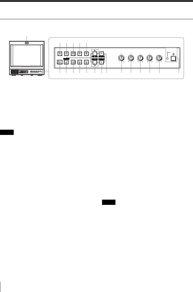
Location and Function of Parts and Controls
Control Panel
w;
qg qh qj qk ql |
|
|
|
|
|
|
||||
LINE |
LINE |
RGB/ |
OPTION OPTION |
|
|
|
|
|
|
|
A |
B |
COMPONENT |
A |
B |
MENU |
BRIGHT |
CHROMA |
PHASE |
CONTRAST VOLUME |
POWER |
|
|
|
|
|
|
|||||
|
|
|
|
|
E X I T |
|
|
|
|
|
|
RESET |
|
|
|
SELECT |
|
|
|
|
|
DEGAUSS BLUE |
UNDER |
16 : 9 |
EXT |
|
– + |
MIN MAX PUR GRN MIN MAX MIN MAX |
|
|||
ENTER |
|
|
|
|
|
|||||
|
ONLY |
SCAN |
|
SYNC |
|
|
|
|
|
|
qf qd qs qa q; 9 87 |
6 |
5 |
4 |
3 2 |
1 |
|||||
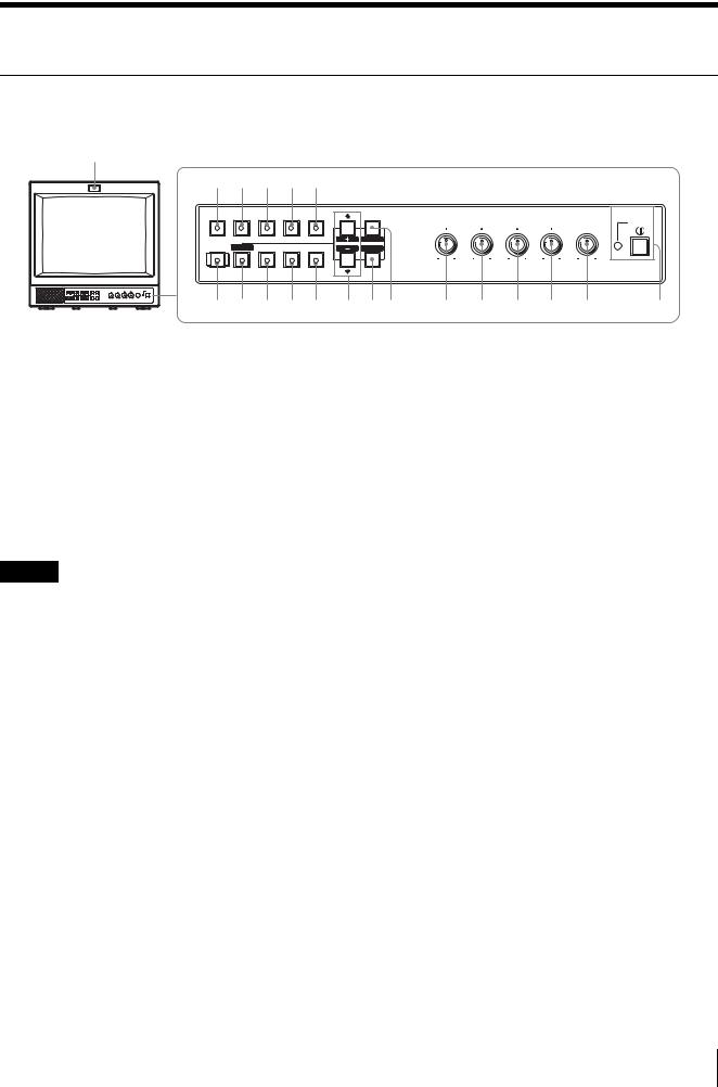
a POWER ! switch
Press this switch to turn on the monitor. The lamp will light up. Press this switch again to turn off the monitor.
b VOLUME control
c CONTRAST control
d PHASE control
k 16:9 button and lamp
Press this button to monitor a signal whose aspect ratio is 16:9.
l UNDERSCAN button and lamp
Press this button for underscanning.
The display size is reduced by approximately 5% so that the four corners of the picture are visible.
m BLUE ONLY/RESET button and lamp
Note
When you use a PAL or component signal, phase cannot be adjusted.
e CHROMA control
f BRIGHT (brightness) control
g MENU/EXIT button
Press this button to show or hide on-screen menus.
h ENTER/SELECT button
Press this button to confirm an item selected on the menu.
iM/+ (move the cursor up/adjust the value) button
m/– (move the cursor down/adjust the value)
button
Press these buttons to move the cursor or adjust an item selected on the menu.
j EXT SYNC (external sync) button and lamp
Press this button to operate the monitor synchronized with an external sync signal input through the EXT SYNC connector.
•As the BLUE ONLY button, press this button to eliminate the red and green component of input signals. Only the blue component of an input signal is displayed on the screen. This facilitates adjustments of chroma and phase, and observation of VCR noise. (Phase adjustment is effective only for NTSC signals.)
•As the RESET button, you can reset the menu item setting to the previous one by pressing this button while the new item is being selected and adjusted.
n DEGAUSS button and lamp
Press this button only once. The screen will be demagnetized. Wait for 10 minutes or more before using this button again.
Note
The DEGAUSS button is disabled when the screen menu is being displayed.
To manually degauss the monitor, first, exit the screen menu by pressing the MENU/EXIT button.
o LINE A button and lamp
Press this button to monitor the signal input through the LINE A connectors.
p LINE B button and lamp
Press this button to monitor the signal input through the LINE B connectors.
24 Location and Function of Parts and Controls

q RGB/COMPONENT button and lamp (for the
PVM-14L2/PVM-20L2 only)
Press this button to monitor the signal input through the RGB/COMPONENT connectors.
r OPTION A button and lamp
This button works when an optional board has been installed in the option slot on the rear panel. Press this button to monitor the video signal input through input 1 of the optional board and the audio signal input through the OPTION AUDIO INPUT 1 jack.
s OPTION B button and lamp
This button works when an optional board has been installed in the option slot on the rear panel. Press this button to monitor the video signal input through input 2 of the optional board and the audio signal input through the OPTION AUDIO INPUT 2 jack.
(This button is disabled if BKM-129X or BKM-155DV is used.)
t Tally lamp
Lights up when a video camera connected to this monitor is selected. For the tally lamp to function properly, certain cabling is required.
For details on this cabling, see page 33.
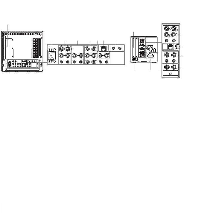
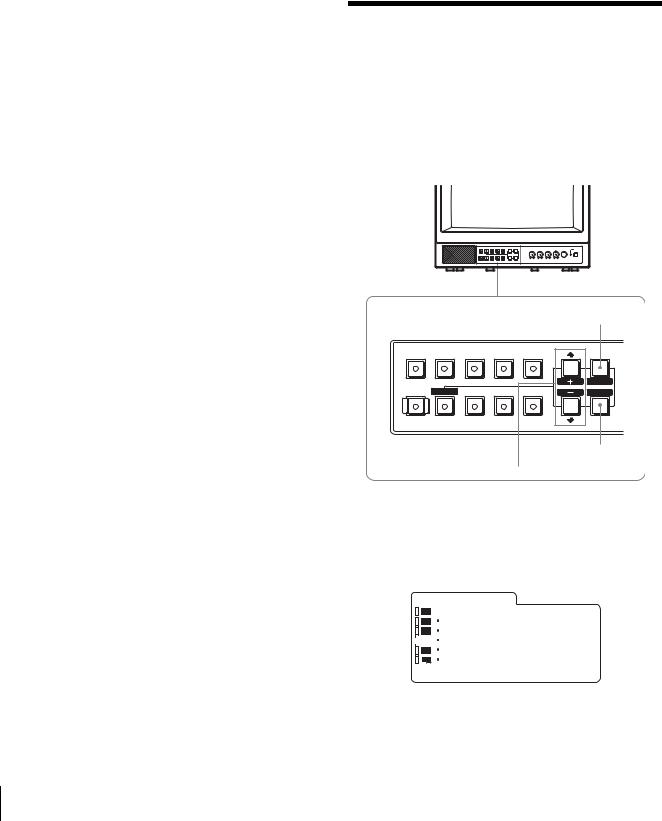
Rear Panel
PVM-14L2/PVM-20L2 |
PVM-9L3/PVM-9L2 |
1
2 3 4
AC IN |
LINE A |
|
|
LINE B |
|
IN |
OUT |
IN |
OUT |
|
VIDEO |
|
|
VIDEO |
1
5 67 8
RGB/COMPONENT |
PARALLEL REMOTE |
OPTION AUDIO INPUT |
|
G/Y |
|
1 |
2 |
IN |
OUT |
IN EXT OUT |
|
B/PB |
SYNC |
IN |
OUT |
IN |
OUT |
IN |
OUT |
IN |
OUT |
AUDIO |
|
|
AUDIO |
|
R/PR |
|
AUDIO |
LINE A |
|
LINE B |
|
– |
+ |
EXT SYNC |
|
OPTION AUDIO INPUT |
|
AC IN |
|
2 q; 9
|
LINE A |
|
IN |
|
OUT |
IN |
VIDEO |
OUT |
IN |
AUDIO |
OUT |
PARALLEL |
REMOTE |
LINE B
IN  VIDEO
VIDEO  OUT
OUT
IN AUDIO OUT
|
EXT SYNC |
IN |
OUT |
1 |
2 |
OPTION AUDIO INPUT
3
7
4
6
8
a Option slot
You can install one optional board for expanding input capability in this option slot. If you install two boards, they do not function.
For details on how to install a board, refer to the user’s manual supplied with the optional board.
b AC IN socket
Connect the supplied AC power cord to this socket and then to a wall outlet.
c LINE A connectors
Line input connectors for Y/C separate, composite video and audio signals and their loop-through output connectors.
Press the LINE A button on the control panel to monitor the input signal through these connectors.
If you input signals to both Y/C IN and VIDEO IN, the signal input to the Y/C IN is selected.
Y/C IN/OUT (4-pin mini-DIN)
These are the input/output connectors for a Y/C separate signal. Connect them to the Y/C separate input/output connectors on equipment such as a VCR, video camera, or another monitor.
VIDEO IN/OUT (BNC)
These are the input/output connectors for a composite video signal. Connect them to the composite video input/output connectors on equipment such as a VCR, video camera, or another monitor.
AUDIO IN/OUT (phono jack)
These are the input/output jacks for an audio signal. Connect them to the audio input/output jacks on equipment such as a VCR.
d LINE B connectors
Line input connectors for composite video and audio signals and their loop-through output connectors. Press the LINE B button on the control panel to monitor the signal input through these connectors.
VIDEO IN/OUT (BNC)
These are the input/output connectors for a composite video signal. Connect them to the composite video input/output connectors on equipment such as a VCR, video camera, or another monitor.
Location and Function of Parts and Controls |
25 |
|
|
AUDIO IN/OUT (phono jack)
These are the input/output jacks for an audio signal. Connect them to the audio input/output jacks on equipment such as a VCR.
eRGB/COMPONENT connectors (for the PVM- 14L2/PVM-20L2 only)
Analog RGB signal or component (Y, PB, PR) signal input connectors and their loop-through output connectors.
Press the RGB/COMPONENT button on the control panel to monitor the signal input through these connectors.
G/Y, B/PB, R/PR IN/OUT (BNC)
These are the input/output connectors for an analog RGB and a component (Y, PB, PR) signal. Unless an external sync signal is input, the monitor is synchronized with the sync signal contained in the G/ Y signal.
AUDIO IN/OUT (phono jack)
When using an analog RGB or a component signal as a video signal, use these jacks for the input/output of an audio signal. Connect them to the audio input/ output jacks on equipment such as a VCR.
f EXT SYNC (external sync) connectors
Press the EXT SYNC button on the control panel to use an external sync signal.
IN/OUT (BNC)
These are the input/output connectors for an external sync signal. Input a reference signal generated by a sync generator to the IN connector. Connect the OUT connector to an external sync signal input connector on equipment which you intend to synchronize with this monitor.
g PARALLEL REMOTE terminal (modular connector)
Forms a parallel switch and controls the monitor externally.
For details on the pin assignment and factory setting function assigned to each pin, see page 33.
h OPTION AUDIO INPUT 1, 2 input connectors
If an optional board has been installed in the option slot, input an audio signal into these connectors. You can connect up to 2 systems. To monitor the audio signals input to OPTION AUDIO INPUT 1 or 2, press either the OPTION A or OPTION B button.
iDC 12V IN connector (XLR) (for the PVM-9L3/ PVM-9L2 only)
Plug the DC 12V power supply to this connector to provide power to the monitor.
This product is intended to be supplied by a Listed Power Unit marked “Class 2” and rated 12 V dc, 4.2 A.
jBattery attachment (for the PVM-9L3/PVM- 9L2 only)
Install the battery here. For the PVM-9L3/PVM-9L2, a Sony lithium-ion battery, the BP-L60A/BP-L90A, or a Sony nickel metal hydride battery, the BP-M50/BP- M100, is applicable.
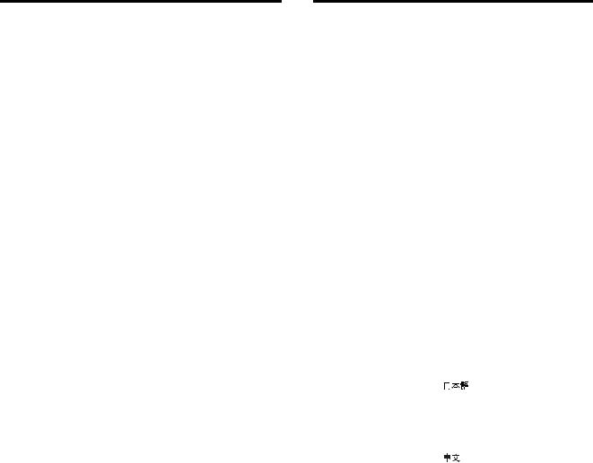
Selecting the Menu
Language
You can select one of seven languages (English, German, French, Italian, Spanish, Japanese, Chinese) for displaying the menus and other on-screen messages. The factory preset language is ENGLISH (English). The current settings are displayed in place of the  marks on the illustrations of the menu screen.
|
|
|
|
|
MENU/EXIT |
|
|
|
|
|
button |
LINE |
LINE |
RGB/ |
OPTION |
OPTION |
|
A |
B |
COMPONENT |
A |
B |
MENU |
|
|
|
|
|
E X I T |
|
RESET |
|
|
|
SELECT |
DEGAUSS |
BLUE |
UNDER |
16 : 9 |
EXT |
ENTER |
|
ONLY |
SCAN |
|
SYNC |
|
|
|
|
ENTER/SELECT
button
M/+, m/– button
1 Press the MENU/EXIT button to display the menu screen, and press the M/+ or m/– button to select  (USER CONFIG), then press the ENTER/ SELECT button.
The USER CONFIG menu appears.
U S E R C O N F I G
|
|
|
|
xR G B / C O M P S E L |
|
xxxx |
|
|
|
|
C O M P L E V E L |
|
xxxxx |
|
|
|
|
|
||
|
|
|
|
|
||
|
|
|
|
N T S C S E T U P |
|
x |
|
|
|
|
F O R M A T D I S P |
|
xxxx |
|
|
|
|
L A N G U A G E |
E N G L I S H |
|
|
|
|
|
D E G A U S S D E L A Y |
x |
|
|
|
|
|
|||
|
|
|
|
|
|
|
2 Press the M/+ or m/– button to select “LANGUAGE,” then press the ENTER/SELECT button.
26 Selecting the Menu Language

The selected item is displayed in yellow.
U S E R C O N F I G
|
|
|
|
R G B / C O M P S E L |
|
xxxx |
|
|
|
|
C O M P L E V E L |
|
xxxxx |
|
|
|
|
|
||
|
|
|
|
|
||
|
|
|
|
N T S C S E T U P |
|
x |
|
|
|
|
F O R M A T D I S P |
|
xxxx |
|
|
|
|
x L A N G U A G E |
E N G L I S H |
|
|
|
|
|
D E G A U S S D E L A Y |
x |
|
|
|
|
|
|||
|
|
|
|
|
|
|
3 Press the M/+ or m/– button to select the desired language, then press the ENTER/SELECT button. The on-screen language changes to the language you have selected.
To clear the menu
Press the MENU/EXIT button.
The menu disappears automatically if a button is not pressed within one minute.
Using the Menu
The monitor is equipped with an on-screen menu for making various adjustments and settings such as picture control, input setting, set setting change, etc.
Follow the instructions below to make adjustments or to change settings.
For details on the menu items, see “Adjustment Using the Menus” on page 28.
You can also change the menu language displayed in the on-screen menu.
To change the menu language, see “Selecting the Menu Language” on page 26.
The current settings are displayed in place of the  marks on the illustrations of the menu screen.
|
|
|
|
|
1 |
LINE |
LINE |
RGB/ |
OPTION |
OPTION |
|
A |
B |
COMPONENT |
A |
B |
MENU |
|
|
|
|
|
E X I T |
|
RESET |
|
|
|
SELECT |
DEGAUSS |
BLUE |
UNDER |
16 : 9 |
EXT |
ENTER |
|
ONLY |
SCAN |
|
SYNC |
|
|
|
|
|||
RESET button |
|
|
2, 3, 4 |
||
1 Press the MENU/EXIT button. The menu appears.
The menu presently selected is indicated by a yellow button.
S T A T U S
|
|
|
|
F O R M A T |
xxxxxxxxx |
|
|
|
|
|
C O L O R T E M P |
|
xxxxxxxx |
|
|
|
|
|
||
|
|
|
|
|
||
|
|
|
|
|
xxx |
|
|
|
|
|
C O M P L E V E L |
|
xxxxx |
|
|
|
|
N T S C S E T U P |
|
x |
|
|
|
|
R G B / C O M P S E L |
xxxx |
|
|
|
|
|
O P T I O N |
|
|
|
|
|
|
|
|
|
2 Press the M/+ or m/– button to select a menu, then press the ENTER/SELECT button.
The menu icon presently selected is shown in yellow and the available setting items are displayed.
Menu |
Setting items |
|
||||||
|
U S E R |
C O N F I G |
|
|
||||
|
|
|
|
|
x R G B / C O M P S E L |
|
xxxx |
|
|
|
|
|
|
C O M P L E V E L |
|
xxxxx |
|
|
|
|
|
|
|
|||
|
|
|
|
|
|
|||
|
|
|
|
|
N T S C S E T U P |
|
x |
|
|
|
|
|
|
F O R M A T D I S P |
|
xxxx |
|
|
|
|
|
|
L A N G U A G E |
E N G L I S H |
||
|
|
|
|
|
D E G A U S S D E L A Y |
x |
||
|
|
|
|
|
||||
|
|
|
|
|
|
|
|
|
3 Use the M/+ or m/– button to select the desired item, then press the ENTER/SELECT button. The item to be changed is displayed in yellow.
Note
If the menu consists of multiple pages, press the M/+ or m/– button to go to the desired menu page.
4 Make the setting or adjustment in an item.
When changing the adjustment level:
To increase the number, press the M/+ button. To decrease the number, press the m/– button.
Press the ENTER/SELECT button to confirm the number, then restore the original screen.
When changing the setting:
Press the M/+ or m/– button to change the setting. Press the ENTER/SELECT button to confirm the setting.
Note
An item displayed in blue cannot be accessed. You can access the item if it is displayed in white.
To clear the menu
Press the MENU/EXIT button.
The menu disappears automatically if a button is not pressed within one minute.
Using the Menu 27

About retaining the settings
The settings are automatically stored in the monitor memory.
To reset items being adjusted
Press the RESET button while the new menu item is being selected and adjusted. Any changes to this new item setting is ignored and the item is reset to the previous setting.
Adjustment Using the
Menus
Items
The screen menu of this monitor consists of the following items.
STATUS1) |
|
||||||
COLOR TEMP/BAL |
|
COLOR TEMP |
|||||
|
|
||||||
USER CONTROL |
|
|
|
MANUAL ADJ |
|||
|
|
|
|||||
|
|
|
AUTO CHROMA/PHASE |
||||
|
|
|
|||||
|
|
|
|
|
|
SUB CONTROL |
|
|
|
|
|
|
|
||
USER CONFIG |
|
|
RGB/COMP SEL2) |
||||
|
|
|
|||||
|
|
|
|
|
|
COMP LEVEL |
|
|
|
|
|
|
|
||
|
|
|
|
|
|
NTSC SETUP |
|
|
|
|
|
|
|
||
|
|
|
|
|
|
FORMAT DISP |
|
|
|
|
|
|
|
||
|
|
|
|
|
|
LANGUAGE |
|
|
|
|
|
|
|
||
|
|
|
|
|
|
DEGAUSS DELAY |
|
|
|
|
|
|
|
||
REMOTE |
|
|
|
|
|
CAPTION3) |
|
|
|
|
|
|
|||
|
|
|
1 PIN |
||||
|
|
|
|||||
|
|
|
|
|
|
2 PIN |
|
|
|
|
|
|
|
||
|
|
|
|
|
|
3 PIN |
|
|
|
|
|
|
|
||
|
|
|
|
|
|
4 PIN |
|
|
|
|
|
|
|
||
|
|
|
|
|
|
6 PIN |
|
|
|
|
|
|
|
||
|
|
|
|
|
|
7 PIN |
|
|
|
|
|
|
|
||
|
|
|
|
|
|
8 PIN |
|
OPTION CONFIG4) |
|||||||
|
|||||||
1)The items on the STATUS menu indicate the current settings.
2)for the PVM-14L2/PVM-20L2 only
3)CAPTION is available only when the Caption Vision (Closed Caption) Decoder has been installed.
4)The items on the OPTION CONFIG menu differ depending on the optional board installed.
Adjusting and Changing the
Settings
 STATUS menu
The STATUS menu is used to display the current status of the monitor.
Submenu |
Setting |
FORMAT |
Display only |
|
|
COLOR TEMP |
Display only |
|
|
COMP LEVEL |
Display only |
|
|
NTSC SETUP |
Display only |
|
|
RGB/COMP SEL |
Display only (for the PVM-14L2/ |
|
PVM-20L2 only) |
|
|
OPTION |
Display only |
|
|
 COLOR TEMP/BAL menu
The COLOR TEMP/BAL menu is used for adjusting the picture white balance.
You need to use a measurement instrument to adjust the white balance.
Submenu |
Setting |
COLOR TEMP |
Select the color temperature from |
|
among D65, D93 and USER |
|
setting. |
|
|
MANUAL ADJ |
If you set COLOR TEMP to USER, |
|
the item displayed is changed from |
|
blue to white, which means you can |
|
adjust the color temperature. |
|
• ADJUST GAIN...: Adjusts the |
|
color balance (GAIN). |
|
• ADJUST BIAS...: Adjusts the |
|
color balance (BIAS). |
|
• COPY FROM: If you select |
|
D65 or D93 with the M/+ or |
|
m/– button, the white |
|
balance data of the selected |
|
color temperature will be |
|
copied to USER. |
|
|
28 Adjustment Using the Menus
 USER CONTROL menu
The USER CONTROL menu is used for adjusting the picture.
Items that cannot be adjusted depending on the input signal are displayed in blue.
Submenu |
Setting |
|
AUTO CHROMA/ |
Adjusts color intensity (CHROMA) |
|
PHASE |
and tones (PHASE). |
|
|
• AUTO ADJ VALUE: Chooses |
|
|
the values to be applied to |
|
|
the chroma and phase from |
|
|
auto adjustment or factory |
|
|
settings. |
|
|
ON: auto adjustment values |
|
|
OFF: factory preset values |
|
|
• START: Displays the color bar |
|
|
signals (Full/SMPTE/EIA) |
|
|
on the screen. To select one, |
|
|
press ENTER/SELECT |
|
|
button. The auto adjustment |
|
|
function starts. After the |
|
|
adjustment has been done |
|
|
correctly, AUTO ADJ |
|
|
VALUE is automatically set |
|
|
to ON. Press the MENU/ |
|
|
EXIT button to exit the |
|
|
adjustment screen. |
|
|
|
|
|
Note |
|
|
If you have selected full color bars, |
|
|
be sure to enter eight color bars. |
|
|
|
|
SUB CONTROL |
You can finely adjust the |
|
|
adjustment range of the following |
|
|
controls on the control panel; the |
|
|
CONTRAST, PHASE, CHROMA |
|
|
and BRIGHT controls. |
|
|
• ADJUST...: adjusts the |
|
|
following items. |
|
|
CONTRAST...: Adjusts the |
|
|
picture contrast. |
|
|
BRIGHT...: Adjusts the picture |
|
|
brightness. |
|
|
CHROMA...: Adjusts the color |
|
|
intensity. The higher the |
|
|
setting, the greater the |
|
|
intensity. |
|
|
The lower the setting, the |
|
|
lower the intensity. |
|
|
PHASE...: Adjusts color tones. |
|
|
The higher the setting, the |
|
|
more greenish the picture |
|
|
becomes. |
|
|
The lower the setting, the |
|
|
more purplish the picture |
|
|
becomes. |
|
|
APERTURE...: Adjusts the |
|
|
picture sharpness. The higher |
|
|
the setting, the sharper the |
|
|
picture. |
|
|
|
|
 USER CONFIG menu
The USER CONFIG menu is used to select a language for the menus and the on-screen messages or to determine the type of video signal acceptable on the RGB/ COMPONENT connectors (Analog RGB or component).
Submenu |
Setting |
RGB/COMP SEL |
According to the type of video |
(for the PVM-14L2/ |
signal which you intend to input to |
PVM-20L2 only) |
the RGB/COMPONENT |
|
connectors, choose between RGB |
|
and COMPONENT. |
|
|
COMP LEVEL |
Select the component level from |
|
among three modes. |
|
SMPTE: 100/0/100/0 signal |
|
BETA 7.5: 100/7.5/75/7.5 signal |
|
BETA 0: 100/0/75/0 signal |
|
|
NTSC SETUP |
Select the NTSC setup level from |
|
two modes. |
|
The 7.5 setup level is used mainly |
|
in North America. The 0 setup level |
|
is used mainly in Japan. |
|
|
FORMAT DISP |
Determines whether the format of a |
|
input signal is displayed on the |
|
screen or not. |
|
ON: The format is always |
|
displayed. |
|
OFF: The format is always |
|
hidden. |
|
AUTO: The format is displayed |
|
for about 10 seconds when the |
|
input of the signal begins. |
|
|
LANGUAGE |
You can select the desired language |
|
for the menus or messages from the |
|
following language options. |
|
: Japanese |
|
ENGLISH: English |
|
DEUTSCH: German |
|
FRANÇAIS: French |
|
ITALIANO: Italian |
|
ESPAÑOL: Spanish |
|
: Chinese |
|
|
DEGAUSS DELAY |
Sets the delay time for auto |
|
degaussing to start working after |
|
the power is turned on. The delay |
|
time can be set within 0 to 99 |
|
seconds. |
|
|
CAPTION |
Selects the caption display mode |
(available only when the |
from among the following options: |
Caption Vision (Closed |
OFF, CAPTION 1, CAPTION 2, |
Caption) Decoder has |
TEXT 1 and TEXT 2. |
been installed.) |
|
|
|
Adjustment Using the Menus |
29 |
|
|

 REMOTE menu
The REMOTE menu is used to assign the functions to the pins of the PARALLEL REMOTE terminal.
Pin 1 to 4 and pin 6 to 8 can be used. The following lists the functions you can assign to the pins.
•– – (No function is assigned.)
•LINE A
•LINE B
•RGB/COMP (for the PVM-14L2/PVM-20L2 only)
•OPTION A
•OPTION B
•TALLY
•UNDERSCAN
•16:9
•EXT SYNC
•BLUE ONLY
•DEGAUSS
Note
If you use the parallel remote function, you need to connect cables.
For more details, see page 33.

 OPTION CONFIG menu
The OPTION CONFIG menu is used to set the optional board installed in the option slot on the rear panel. Depending on the board installed, the screen displayed may differ. If no board is installed, the item settings are not displayed. After assigning the input signal, be sure to adjust the monitor’s AUTO CHROMA/PHASE.
When installing the BKM-150CP optional board:
Submenu |
Setting |
FORMAT |
Sets the signal type. |
|
Select SDTI-CP or D1-SDI. |
|
|
AUDIO |
Selects an audio channel. |
|
D1-SDI |
|
Select from among CH1+CH2 |
|
through CH15+CH16, or CH1 |
|
through CH16. |
|
SDTI-CP |
|
Select from among CH1+CH2 |
|
through CH7+CH8, or CH1 |
|
through CH8. |
|
The audio signal input to the |
|
OPTION AUDIO INPUT 1/2 jack |
|
is ignored. |
|
|
TIME CODE |
Selects the time code display. |
|
D1-SDI |
|
Select VITC, RP188 or OFF. |
|
SDTI-CP |
|
Select VITC, CP-TC1, CP-TC2, |
|
ES-TC1, ES-TC2 or OFF. |
|
|
The following lists the abbreviations in the menu and their full names:
• CP-TC1:
• CP-TC2:
• ES-TC1:
• ES-TC2:
• RP188:
• VITC:
When installing the BKM-155DV optional board:
Submenu |
Setting |
AUDIO |
Selects an audio channel. |
|
Select from among CH1+CH2, |
|
CH3+CH4, CH1/3, CH2/4, CH1/ |
|
3+CH2/4, or CH1 through CH4. |
|
OPTION AUDIO INPUT 1/2 jack |
|
is ignored. |
|
|
When installing the BKM-120D or BKM-129X optional board:
The serial number of the board is displayed on the OPTION CONFIG menu.
If the cooling fan in the BKM-150CP or BKM-155DV is stopped, the screen shows the following message in red “BKM-xxxxx FAN ERROR”. In this case, you cannot select Option A or Option B.
Troubleshooting
This section may help you isolate the cause of a problem and as a result, eliminate the need to contact technical support.
•The display is colored green or purple. t Select the correct input by pressing one of the buttons related to input.
•The signal input through the RGB/COMPONENT input connectors does not appear on the screen (for the PVM-14L2/PVM-20L2 only). t Set RGB/ COMP SEL on the USER CONFIG menu appropriately according to type of input signal.
•The BKM-150CP or BKM-155DV has been installed. The error message “BKM-xxxxx FAN ERROR” is displayed and you cannot select Option A or Option B. t Repair the BKM-xxxxx.
30 Troubleshooting
 Loading...