


UVW-1800P

SONY
Videocassette Recorder
3-757-561-24(2)
Model:
UVW-1800/1800P
Operating Instructions
Before operating the unit, please read this manual thoroughly
and retain it for future reference.
Mode d'emploi
Avant la mise en service de cet apparail, priere de lire
attentivement ce mode d'emloi que I'on conservera pour toute
reference ulterieure.
page-i(F)
pagei(E)
© 1993 by Sony Corporation
Owner's Record
The model and serial numbers are located at the rear.
Record the serial number in the space provided below.
Refer to these numbers whenever you call upon your
Sony dealer regarding this product
Model No. UVW-1800 Serial No. -
WARNING
To prevent fire or shock hazard, do not
expose the unit to rain or moisture.
RISK OF ELECTRIC SHOCK
DO NOT OPEN
CAUTION TO REDUCE THE RISK OF ELECTRIC SHOCK
DO NOT REMOVE COVER (OR BACK)
NO USER-SERVICEABLE PARTS INSIDE
REFER SERVICING TO QUALIFIED SERVICE PERSONNEL
For the customers in USA
This equipment has been tested and found to comply
with the limits for a Class A digital device, pursuant to
Part 15 of the FCC Rules These limits are designed to
provide reasonable protection against harmful
interference when the equipment is operated in a
commercial environment This equipment generates,
uses, and can radiate radio frequency energy and, if not
installed and used in accordance with the instruction
manual, may cause harmful interference to radio
communications Operation of this equipment in a
residential area is likely to cause harmful interference in
which case the user will be required to correct the
interference at his own expense
You are cautioned that any changes or modifications not
expressly approved in this manual could void your
authority to operate this equipment.
The shielded interface cable recommended in this
manual must be used with this equipment in order to
comply with the limits for a digital device pursuant to
Subpart B of Part 15 of FCC Rules.
For the customers in Canada
This apparatus complies with the Class A limits for radio
noise emissions set out in Radio Interference
Regulations.
This symbol is intended to alert the
user to the presence of uninsulated
"dangerous voltage" within the
product's enclosure that may be of
sufficient magnitude to constitute a
risk of electric shock to persons.
This symbol is intended to alert the
user to the presence of important
operating and maintenance
(servicing) instructions in the
literature accompanying the
appliance.
Caution
Television programs, films, video tapes and other
materials may be copyrighted Unauthorized
recording of such material may be contrary to the
provisions of the copyright laws
Pour les utilisateurs au Canada
Cet appareil est conforme aux normes Classe A pour
bruits radioelectnques, specifies dans Ie Reglement sur
Ie brouillage radioelectnque.
For the customers in the United Kingdom
WARNING
THIS APPARATUS MUST BE EARTHED
IMPORTANT
The wires in this mains lead are coloured in
accordance with the following code:
Green-and-yellow Earth
Blue Neutral
Brown: Live
As the colours of the wires in the mains lead of this
apparatus may not correspond with the coloured
markings identifying the terminals in your plug proceed
as follows
The wire which is coloured green-and-yellow must be
connected to the terminal in the plug which is marked
by the letter E or by the safety earth symbol ^ or
coloured green or green-and-yellow
The wire which is coloured blue must be connected to
the terminal which is marked with the letter N or
coloured black
The wire which is coloured brown must be connected
to the terminal which is marked with the letter L or
coloured red.
Precautions ..........................................................................................3 (E)
Features...............................................................................................1-2 (E)
Front Panel ..................................................................................... 2-2 (E)
Rear Panel........................................................................................... 2-5 (E)
Before Use ........................................................................................... 3-2 (E)
Cassettes..............................................................................................3-3 (E)
Cassettes Which Can Be Used ....................................................3-3 (E)
Inserting and Ejecting a Cassette ................................................3-3 (E)
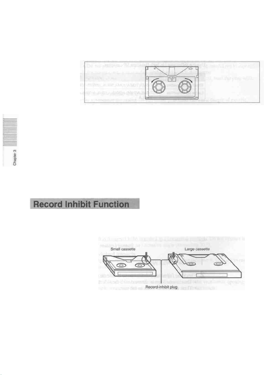
Record Inhibit Function ..............................................................3-4 (E)
Reference Video Signals ....................................................................3-5 (E)
Playback Operation ........................................................................... 4-2 (E)
Preparation for Playback............................................................. 4-2 (E)
Playback Operation .....................................................................4-3 (E)
Recording Operation ......................................................................... 4-4 (E)
Preparation for Recording ...........................................................4-4 (E)
Recording Operation ...................................................................4-6 (E)
Superimposed Text Information.......................................................4-7 (E)
Cut Editing.......................................................................................... 5-2 (E)
A/B Roll Editing .................................................................................5-6 (E)
Phase
Adjustments...........................................................................5-11 (E)
Displaying Time Data ........................................................................6-2 (E)
Settings for Longitudinal Time Code and User Bits .......................6-3 (E)
Synchronizing the Internal Time Code Generator With an
External Time Code Generator ................................................6-6 (E)
Contents
Menu Organization............................................................................7-2 (E)
Hierarchical Structure .................................................................7-2 (E)
Menu Screens..............................................................................7-3 (E)
Menu Operations................................................................................7-8 (E)
Buttons Used to Change the Setting............................................7-8 (E)
Operation Sequence ....................................................................7-9 (E)
Self-Diagnosis Functions.................................................................... 8-2 (E)
Condensation .......................................................................................8-3 (E)
Regular Checks and Maintenance.................................................... 8-4 (E)
Digital Hours Meter ....................................................................8-4 (E)
Head Cleaning............................................................................. 8-5 (E)
Alarm Messages.................................................................................. 9-2 (E)
Trouble-Shooting Chart.................................................................... 9-4 (E)
Specification.......................................................................................A-2(E)
Glossary.............................................................................................. A-6 (E)
Index ....................................................................................................1-1 (E)
2 (E) Contents

To take best advantage of the many features of this unit, note the following
important points.
Usable
Use only metal cassette tapes with this unit. Do not use oxide tapes.
Reference video input (see page 3-5(E))
When recording or playing back videotapes on this unit, always input a composite
video signal synchronized with the video signal to be used to the REF. VIDEO
INPUT connector. Especially when recording and editing, failure to input a
reference video signal to the REF. VIDEO INPUT connector will prevent the builtin time base corrector (TBC) from functioning correctly, causing picture breakup.
Even if you are recording only audio signal or time code, do not fail to input a
reference video signal.
cassette
tapes
(see page 3-3(E))
Input video signal type selection (see page 4-5(E))
For recording, it is important that the VIDEO IN switch on the subsidiary control
panel is correctly set to match the type of video signal input. In particular, when
inputting a component signal, set this switch to the "Y-R,B" position, and set the
component signal input connector selection switch on the rear panel to the
appropriate position. If these switches are not set correctly, not only will recording
not be possible, but the input signal will also not appear on the monitor.
Setting the cassette record-inhibit plug (see page 3-4(E))
Recording on a cassette is impossible when its record-inhibit plug is pushed in. If
the record-inhibit plug is pushed in on the cassette you are going to use, either use
a new tape, or pull out the plug and use the tape after making sure that it contains
no important material.
Controlling tape transport remotely (see page 7-3(E))
The tape transport buttons on this unit are normally disabled when the REMOTE
indicator is lit. However, you can use these buttons if you set the LOCAL
ENABLE menu item to ALL ENABLE. The factory default setting for this item is
STOP & EJECT.
Storing in a rack
When installing this unit in a standard 19-inch rack, you can stack up to three units
in one rack. When stacking four or more units, be sure to leave space equivalent to
one unit height, or 44.45 mm (1 3/4 inches) between units.
Precautions 3 (E)

Chapter 1
Overview________
This chapter overviews the features of the UVW-1800/1800P.
Features......................................................................... 1.2 (E)

The UVW-1800/1800P is a Betacam SP videocassette recorder, capable of
recording and playing back composite video, component video and analog audio
signals. With an external control unit connected, jog and shuttle functions are
available, and the unit can be used as the recorder in an editing system.
Betacam SP format
Excellent video and audio characteristics
Compared with a conventional format, Betacam SP format provides better video
and audio performance, with improved signal-to-noise ratio, frequency
characteristics, and detail reproduction, and greatly enhanced overall video and
audio quality.
Compatibility with other Betacam SP VTRs
A metal tape cassette recorded on this unit can also be played back on other
Betacam SP VTRs. Again, metal tape cassettes recorded on other Betacam SP
VTRs can be played back on the UVW-1800/1800P. The cassette size is detected
automatically.
Full range of recording and playback functions
Built-in time code generator and reader
The built-in time code generator allows the unit to record time codes (LTC or user
bits) simultaneously with the video and audio signals. The built-in time code
reader allows the unit to read time codes (LTC or user bits) from a tape.
Built-in time base corrector (TBC)
The built-in time base corrector allows you to obtain a stable playback picture with
no horizontal jitter or color fluctuation.
Microprocessor servo system
Four microprocessor-controlled DC motors provide direct drive for the drum,
capstan and reels, enabling quick and accurate tape access.
Audio noise reduction
Longitudinal audio tracks 1 and 2 use the same Dolby C-type noise reduction
21
as a
conventional Betacam SP system. These circuits are always operating when
recording or playing back.
1) Because this unit does not record the AFM carrier 2) Dolby noise reduction manufactured under license
wave, noise may be heard when tapes recorded on from Dolby Laboratories Licensing Corporation.
this unit are played back by other VTRs in the BVW "DOLBY" and the double-D symbol DO are
series. If necessary, lower the audio levels of trademarks of Dolby Laboratories Licensing
channels 3 and 4 on the other VTR. Corporation.
-|-2 (E) Chapter 1 Overview

Other features
Compact, power-saving design
The unit is light and simple, and very energy-efficient.
Menu-based set-up system
All the initial settings for system operation conditions and so forth are accessed
through a simple menu system, from the subsidiary control panel.
Remote control function
The unit can be operated from a remote control unit through the RS-422A serial
interface.
It is also possible to use the CONTROL S connector on the front panel to connect a
simple remote control unit (SIRCS type remote control unit such as an SVRM-100)
to carry out search operations.
Digital hours meter
The digital hours meter keeps cumulative totals of four values: the total hours
powered on, the drum rotation time, the tape running time, and the numbering of
threading/unthreading operations. These are displayed as superimposed text on the
video monitor.
Superimposed text output
The VIDEO 2 (SUPER) OUTPUT connector provides a monitor video output
which can have various information (time codes, tape speed, system settings, etc.)
superimposed on it. The superimpose function can be enabled or disabled as
required.
S-Video connectors
With VTRs or other peripheral equipment having S-Video connectors, these
connectors provide a high-grade interface for video signal transfer.
Self-diagnosis functions
If an operating fault occurs, the system attempts to diagnose the problem, and
produces an error code on the time counter display and superimposed video output.
Alarm indications
If an erroneous operation or connection is made, the system superimposes
information on the monitor screen giving nature of the error and actions to be
taken. The cause of the problem is also indicated in the time counter display.
Chapter 1 Overview 1-3 (E)

Chapter 2
Identification of Parts
and
This chapter lists the names of all the controls and other
components used in the operation of the unit
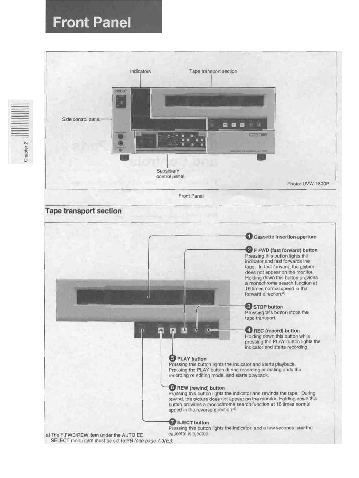
Front Panel ......................................................................2-2 (E)
Rear Panel .......................................................................2-5 (E)
Controls______
2-2 (E) Chapter 2 Identification of Parts and Controls
Tape transport section

Video inputs
Rear Panel
2-5 Chapter 2 Identification of Parts and Controls
Video inputs
Side control panel
Side control pane
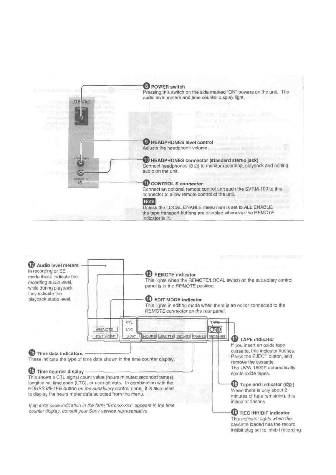
Indicators
Indicators
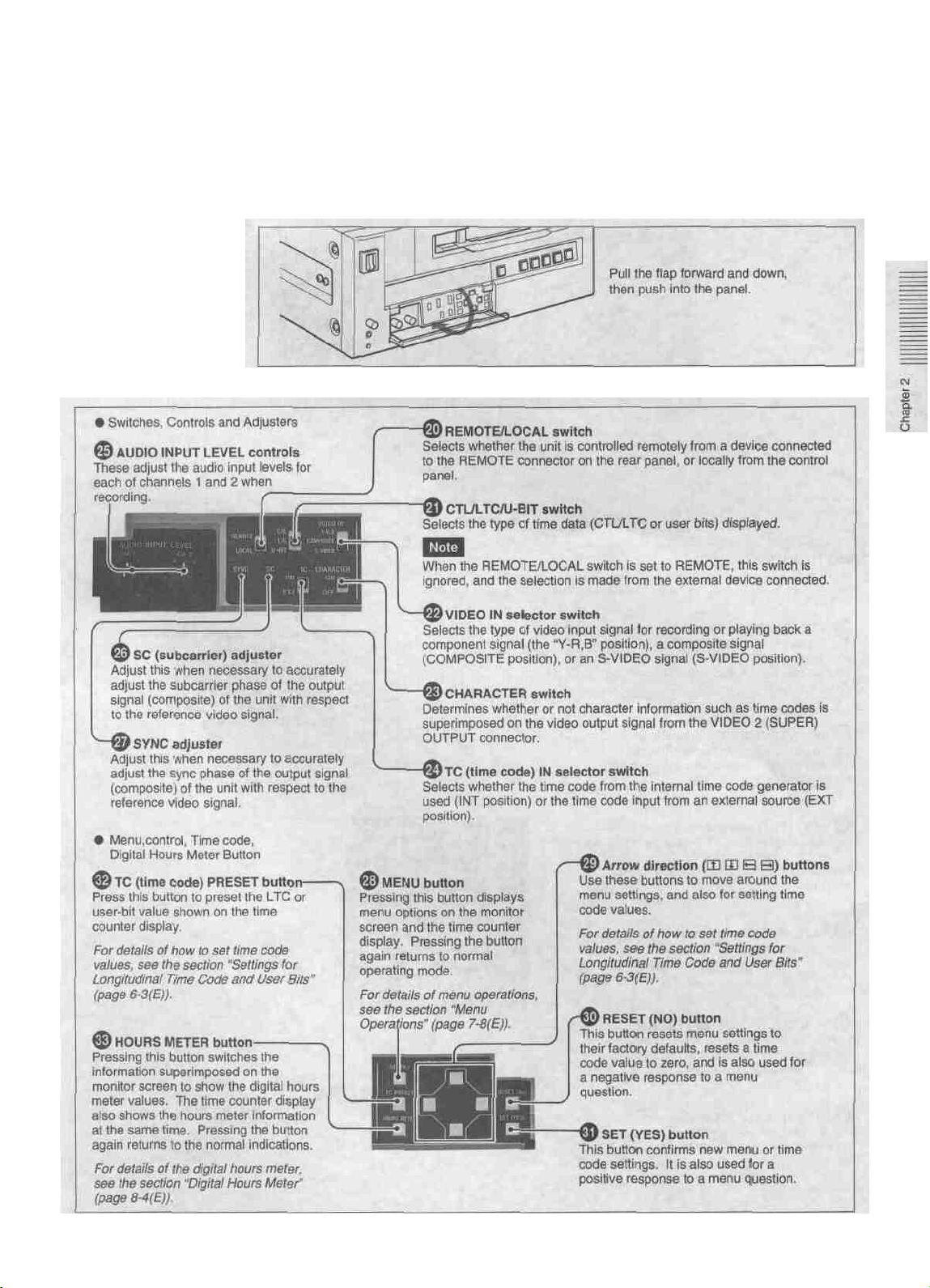
Subsidiary control panel
The subsidiary control panel is behind a flap on the front panel. Open the flap as
shown in the figure.
Accessing the subsidiary control panel
Subsidiary control panel
Chapter 2 Identification of Parts and Controls 2-4

Video outputs
Audio inputs and outputs
Video outputs
Audio inputs and outputs
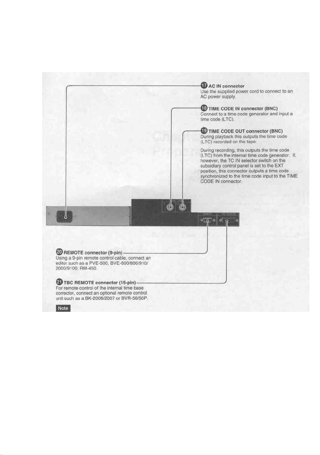
Power, time code and control signals
Always power off the UVW-1800/1800P before
connecting a remote control unit to the TBC
REMOTE connector
(Load current: Max. 300mA)
Power, time code and control signals
Chapter 2 Identification of Parts and Controls 2-7 (E)

Chapter 3
Preparations______
This chapter describes various preparatory aspects of operation
of the UVW-1800/1800P.
Before
Cassettes .......................................................................... 3-3 (E)
Reference Video Signals................................................. 3-5 (E)
Use
........................................................................3-2
Cassettes Which Can Be Used.
Inserting and Ejecting a Cassette................................ 3-3 (E)
Record Inhibit Function............................................... 3-4 (E)
.......
............................3-3
(E)
(E)
Safety notes
Notes on operation
Power supply
• Ensure that the unit is "connected to a power supply of the correct rating.
• Do not place any heavy objects on the power cord, and be careful not to damage
the power cord. Using a damaged power cord is dangerous.
• When disconnecting the power cord, not pull the cord itself, hold the plug while
pulling it out.
Do not dismantle the unit
Do not remove the casing. If you insert your hand there is a danger of electric
shock.
Do not drop foreign objects into the casing
If flammable objects, metal objects, water or other undesirable substances enter the
casing, this can be a cause of malfunction.
In the event of a malfunction
If there should be a strange sound or smell or smoke emanating from the unit,
immediately power off the unit, and disconnect the power supply and all signal
connections, then refer to your supplier or Sony service representative.
Operation and storage locations
Avoid operation or storage in any of the following places.
• Locations subject to extremes of temperature (operating temperature range 5 °C
to 40 °C (41 °Fto 104°F))
• Locations subject to direct sunlight for long periods, or close to heating
appliances (Note that the interior of a car left in summer with the windows
closed can exceed 50 °C (122 °F)).
Operate the unit in a horizontal position
This unit is designed to be operated in a horizontal position. Do not operate it on
its side, or tilted through an excessive angle (exceeding 20 °).
Avoid violent impacts
Dropping the unit, or otherwise imparting a violent shock to it, is likely to cause it
to malfunction.
Do not obstruct ventilation openings
To prevent the unit from overheating, do not obstruct the ventilation openings, by
for example wrapping the unit in a cloth while it is in operation.
Care
If the casing or panel is dirty, wipe it gently with a soft dry cloth. In the event of
extreme dirt, use a cloth steeped in a neutral detergent to remove the dirt, then
wipe with a dry cloth. Applying alcohol, thinners, insecticides, or other volatile
solvents may result in deforming the casing or damaging the finish.
3-2 (E) Chapter3 Preparations
Shipping
• Always remove the cassette before shipping the unit.
• Pack the unit in its original carton or equivalent packing, and take care not to
impart violent shocks in transit.
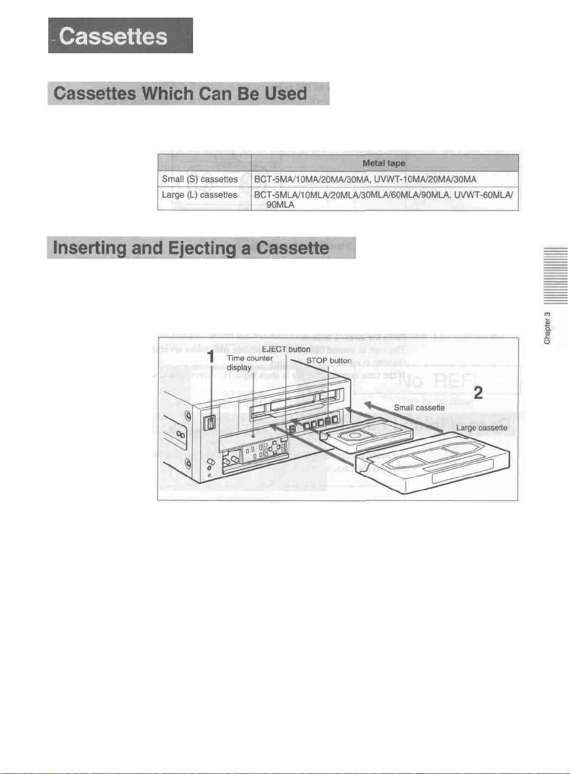
Inserting a cassette
This unit only accepts metal tapes.
Use the following '/2-inch Betacam SP cassettes.
Always check that the unit is powered on before attempting to insert or eject a cassette.
Inserting a cassette
1 Turn the POWER switch on.
2 Check the following points, then insert the cassette.
• The cassette must be inserted with the side that the tape is visible uppermost.
• There must be no slack in the tape.
• There must be no message "HUMID !" in the time counter display.
For details of how to remove slack in the tape, see the section "Removing slack in the
tape " (on the next page ).
If the message "HUMID !" appears in the time counter display, see Section
"Condensation " (page 8-3(E)).
To insert a small cassette, align it with the marks on the cassette compartment.
The cassette is automatically drawn into the unit, and the tape wound round the
head drum. The tape is stationary while the head drum rotates, and the STOP
button lights.
Chapters Preparations 3-3 (E)
Cassettes
Removing slack in the tape
Carefully retote one of the reels with your finger in the direction of the arrows until
it stops.
No double insertion of cassettes
When you insert a cassette, the orange lock-out plate appears in the cassette
compartment to prevent double insertion.
Ejecting the cassette
Removing slack in the tape
Press the EJECT button.
The tape is wound back into the cassette (this takes several seconds), and then the
cassette is ejected from the unit.
If the time counter display is showing CTL values, it is reset.
To protect recorded material which you wish to keep, press in the record-inhibit
plug on the cassette.
3-4 (E) Chapter 3 Preparations
Record-inhibit plug
When you insert a cassette with the record-inhibit plug pushed in into the cassette
compartment, the REC INHIBIT indicator lights, and it is not possible to record.
To re-record on the cassette, return the record-inhibit plug to its original position.
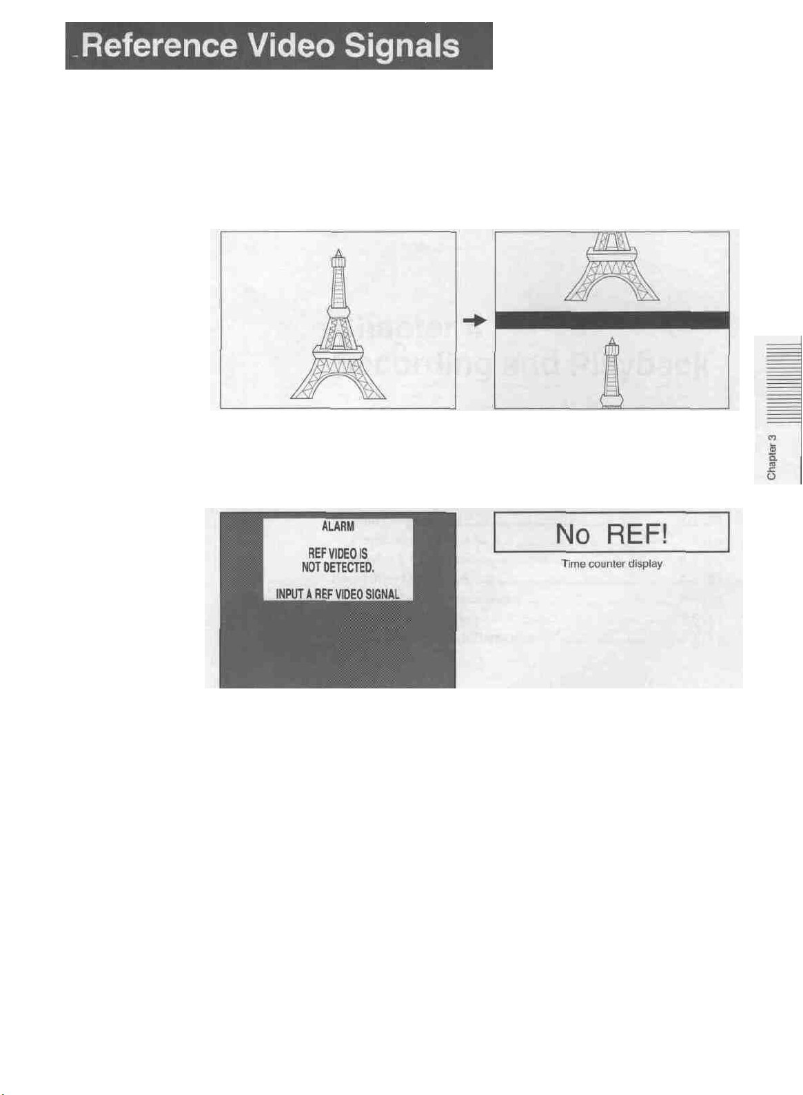
When this unit is being used, a composite video signal, synchronized to the signal
being used must be input to the REF. VIDEO INPUT connector to enable the time
base corrector (TBC) to operate correctly, and ensure stable operation.
If no reference video signal is input, then during recording or editing, or in EE
mode the monitor screen will tend to drift vertically, as shown in the figure below.
With reference video
No reference video
The monitor screen and the time counter display also show alarm messages.
(Example: When the VIDEO 2 (SUPER) OUTPUT connector is used with the
"REF. ALARM" set to ON in the menu.)
Monitor screen
During playback, a monitor picture is normally stable without a reference video
signal input.
For details of changing the menu settings, see the section "Menu Operations" (page 78(E)).
Chapter 3 Preparations 3-5 (E)

Chapter 4
Recording and Playback
This chapter describes the preparation necessary before using
the unit for recording or playback, including connections and
switch settings, and basic operating procedures. It also
describes the text information which can be superimposed on
the monitor screen.
Playback Operation ........................................................4-2 (E)
Preparation for Playback..............................................4-2 (E)
Playback Operation..................................................... 4-3 (E)
Recording Operation...................................................... 4-4 (E)
Preparation for Recording............................................4-4 (E)
Recording Operation.................................................... 4-6 (E)
Superimposed Text Information ...................................4-7 (E)
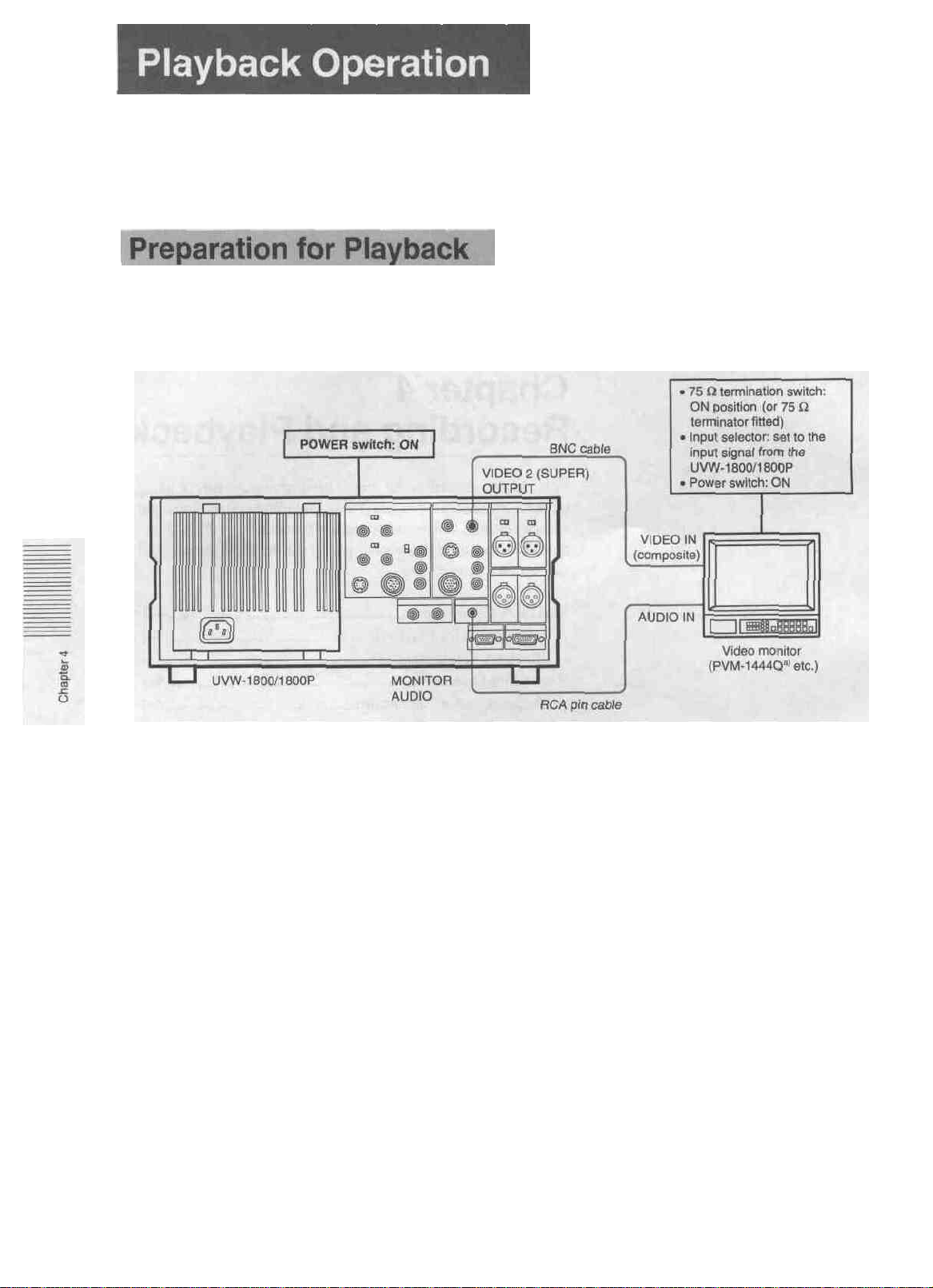
This section describes the connections, switch settings, and basic operating
procedures for playback of both video and audio signals.
Connect the unit to the monitor and make the switch settings as shown in the
following figure.
a) The VIDEO IN connectors of the PVM-1444Q are provided with automatic termination function.
Connections and switch settings
4-2 (E) Chapter 4 Recording and Playback
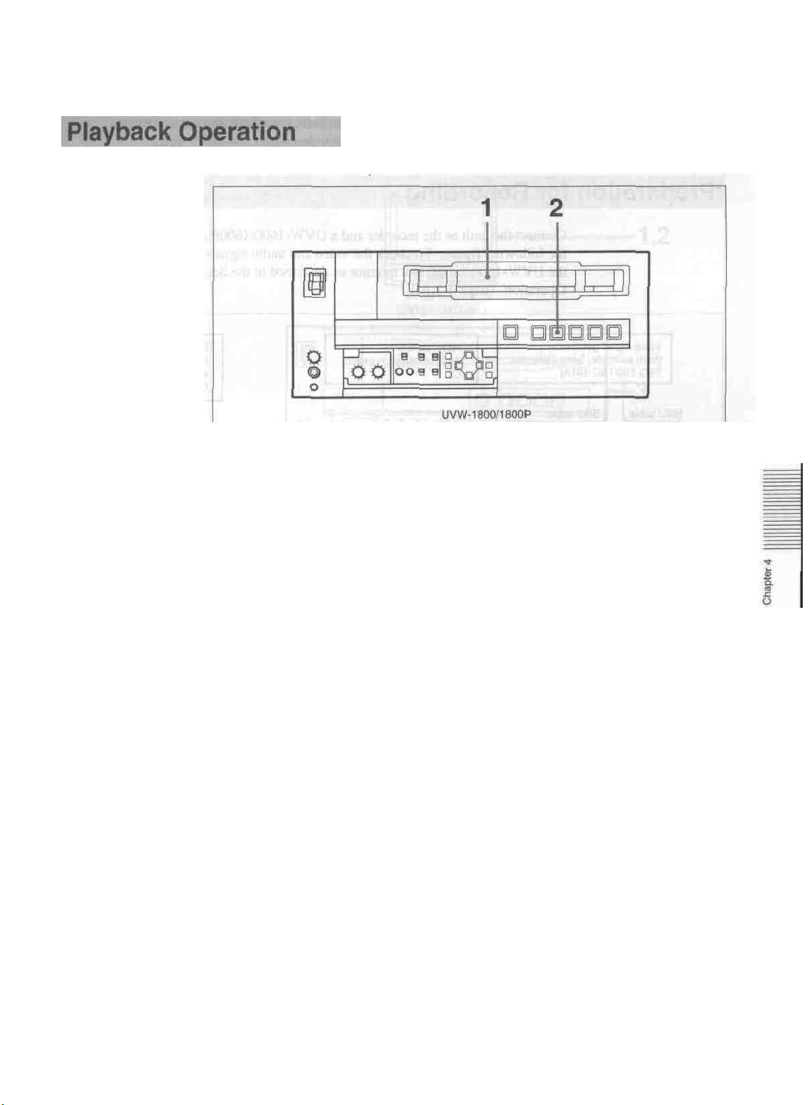
Operation
1 Insert a cassette.
The STOP button lights, then a few seconds later the tape is ready to start
running. At this point a still picture appears on the monitor.
Always be sure to use a metal tape.
2 Press the PLAY button.
Playback begins.
To stop playback
Press the STOP button.
This puts the UVW-1800/1800P into stop mode. This unit automatically enters
standby-off mode if it is left in stop mode for eight minutes.
You can change the time to switch to stand-by off mode in the TAPE
PROTECTION menu. For details, see under "TAPE PROTECTION" (page 76(E)).
If the tape reaches the end during playback
The tape is automatically rewound to the beginning and the unit stops.
You can disable this automatic rewind function using the menu.
For details, see "AUTO REW" (page 7-3 (E)).
Adjusting the audio playback volume
Carry this out on the monitor.
Simple search function
With the F. FWD/REW item in the AUTO EE SELECT of OPERATIONAL
FUNCTION menu set to PB, holding down the F FWD or REW button provides a
monochrome search function at 16 times normal speed in the toward or reverse
direction respectively. Press the PLAY button again to return to normal playback.
Chapter 4 Recording and Playback 4-3 (E)
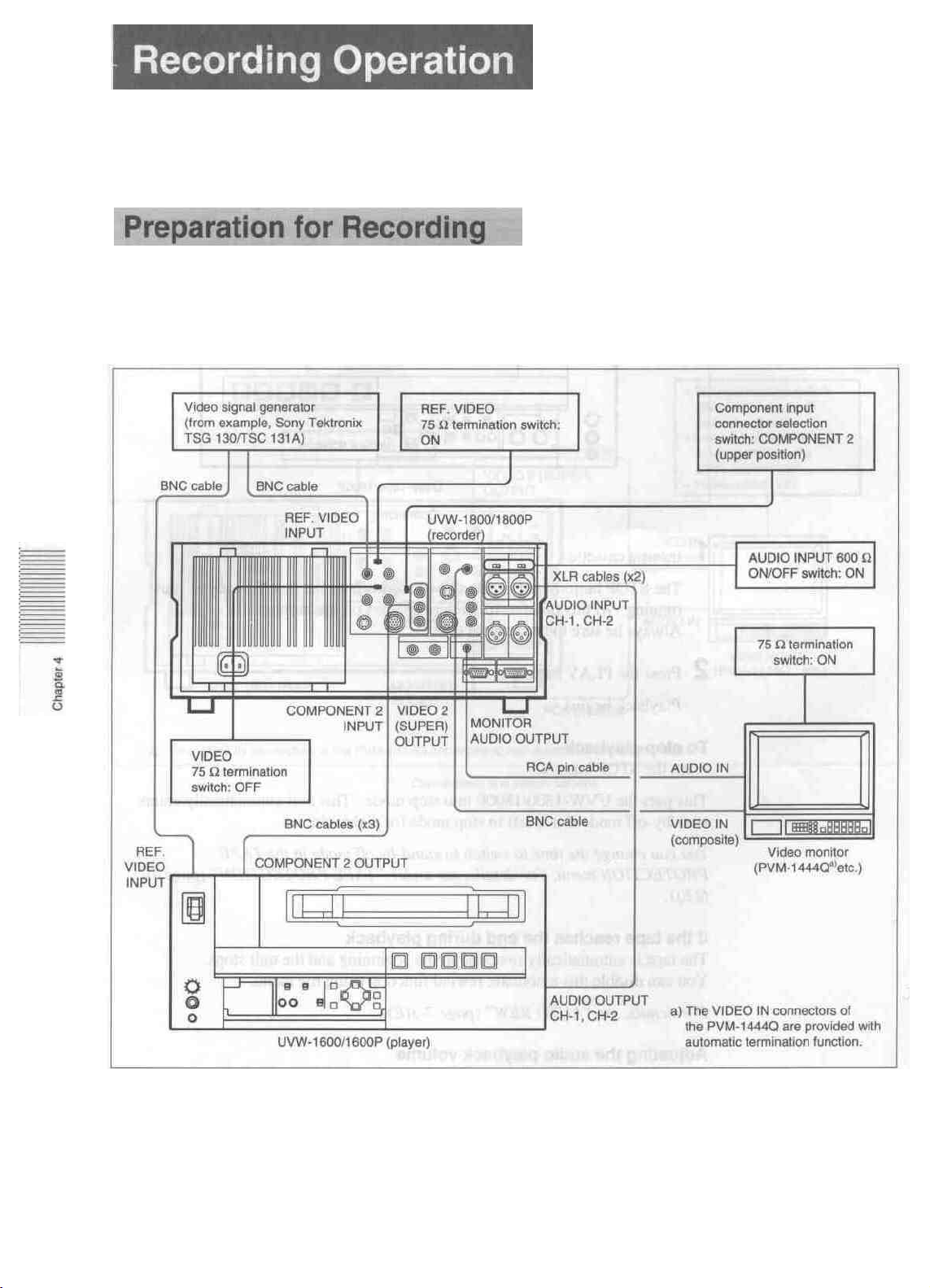
This section describes the connections, switch settings, and basic operating
procedures for recording a component video signal and audio signal.
Connect this unit as the recorder and a UVW-1600/1600P as the player as shown in
the following figure. To check the video and audio signals being recorded, connect
the UVW-1800/1800P to a monitor as described in the Section "Playback
Operation" (page 4-2(E)).
CB3
If you do not input a reference video signal, the monitor picture will be subject to
vertical instability. When carrying out recording, always input a reference video
signal.
For details of reference video signals, see the Section "Reference Video Signals" (page 3-5(E)).
4-4 (E) Chapter 4 Recording and Playback
Connections
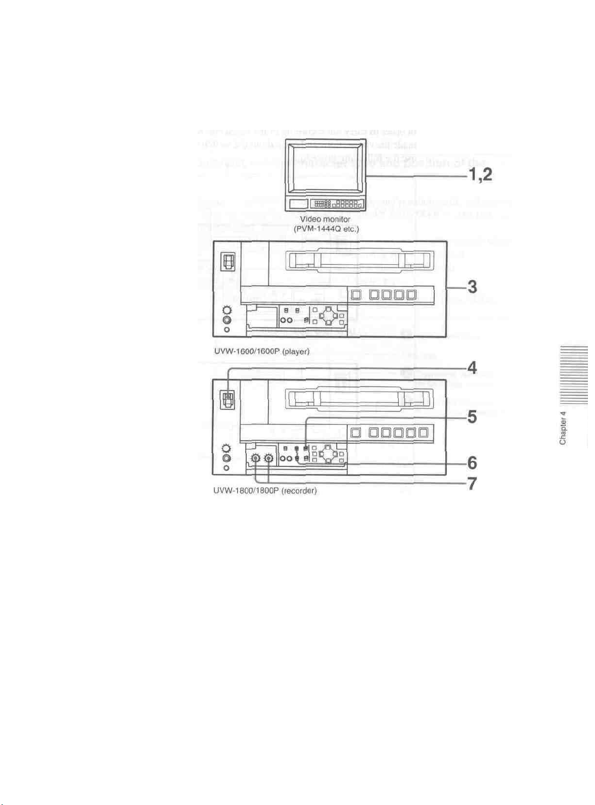
Switch and control settings
After completing the connections, make the switch and control settings as follows.
Switch and control settings
I Power on the video monitor.
2 Set the input selector of the monitor to the input connector connected to the
UVW-1800/1800P.
3 Following the instructions in the appropriate operation manual, and prepare the
player for playback.
4 Power on the UVW-1800/1800P.
5 Set the VIDEO IN selector switch to Y-RJB.
6 Set the time counter display selector switch according to the time data to be
used.
7 Adjust the AUDIO INPUT LEVEL controls so that the audio level meters
indicate around 0 VU when the audio signal is at its maximum.
Chapter 4 Recording and Playback 4-5 (E)
 Loading...