


UWP-D16

Wireless Microphone
4-530-735-12 (1)
Package
Operating Instructions
Before operating the unit, please read this manual thoroughly
and retain it for future reference.
UWP-D11/D12/D16
© 2014 Sony Corporation

Table of Contents
Configuration of the Packages ..................3
UWP-D11 ..................................................... 3
UWP-D12 ..................................................... 4
UWP-D16 ..................................................... 5
Models available separately.......................... 6
Features .......................................................7
UWP-D11 ..................................................... 7
UWP-D12 ..................................................... 7
UWP-D16 ..................................................... 7
Name and Function of Parts.......................8
Body-pack transmitter (UTX-B03)............... 8
Hand-held microphone (UTX-M03)............. 9
Plug-on transmitter (UTX-P03).................. 11
Portable diversity tuner (URX-P03) ........... 12
Power Supply.............................................14
Inserting the batteries.................................. 14
Supplying power from a USB connector.... 15
Charging nickel metal hydride batteries ..... 16
Attaching Accessories..............................16
Attaching accessories to the body-pack
transmitter (UTX-B03)...................... 16
Attaching accessories to the hand-held
microphone (UTX-M03) ................... 17
Attaching accessories to the plug-on
transmitter (UTX-P03) ...................... 17
Attaching accessories to the portable
diversity tuner (URX-P03) ................ 18
Operation ...................................................19
If noise is generated .................................... 19
Tuner Settings ...........................................20
Menu structure and operation ..................... 20
Setting the receive channel ......................... 21
Searching for available channels within a
group (Clear Channel Scan) .............. 21
Searching for active channels within a group
(Active Channel Scan) ...................... 22
Adjusting the monitor audio level .............. 22
Configuration menu.................................... 23
Transmitter Settings .................................25
Menu structure and operation ..................... 25
Setting the transmit channel........................ 26
Configuration menu.................................... 27
System Configuration Examples .............30
Error Messages .........................................31
Troubleshooting........................................32
Important Notes on Use............................34
Usage and storage ....................................... 34
Cleaning...................................................... 34
Specifications............................................34
Transmitter (UTX-B03/M03/P03).............. 34
Tuner........................................................... 36
Table of Contents
2

Configuration of the Packages
This manual is for the UWP-D11/D12/D16 Wireless Microphone Packages. The contents of each package are described
below.
Note
Some of the packages may not be available in certain countries or areas.
For details, consult your Sony dealer.
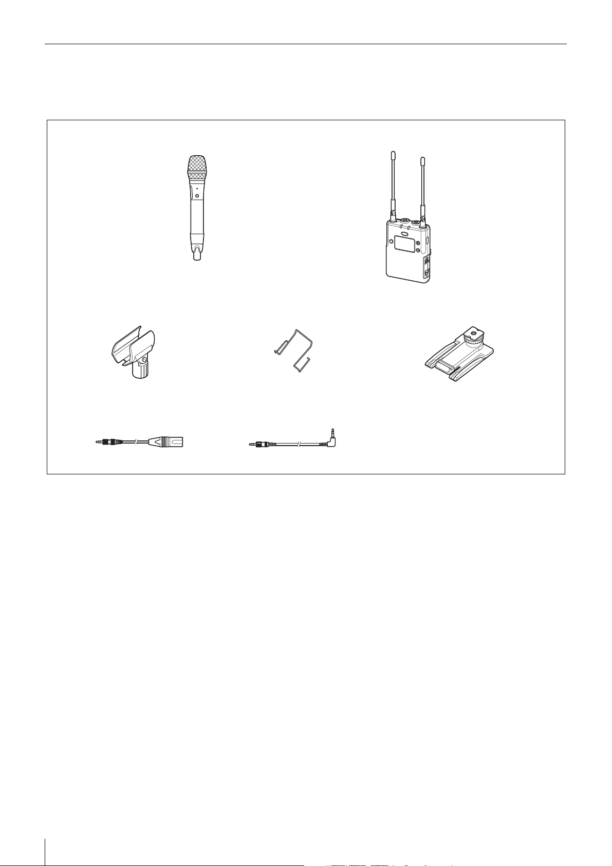
UWP-D11
The package consists of a body-pack transmitter (UTX-B03), a portable diversity tuner (URX-P03), and their accessories.
When used in conjunction with a compact camcorder, a mobile system for ENG (Electronic News Gathering) or EFP
(Electronic Field Production) applications can be constructed.
Body-pack transmitter
(UTX-B03) (1)
Supplied accessories
Portable diversity tuner
(URX-P03) (1)
Wind screen (1)Omni-directional lavalier microphone (1) Holder clip (1)
Shoe mount adapter (1) Belt clip (2)
XLR-BMP conversion output cable
for the URX-P03 (1)
Stereo mini plug-BMP conversion
cable (1)
Battery case (1)
(Chinese model only)
Before Use (1)
Quick Start Guide (1)
CD-ROM (1)
Warranty card (1)
(North American and Korean models only)
Configuration of the Packages
3
UWP-D12
The package consists of a hand-held microphone (UTX-M03), a portable diversity tuner (URX-P03), and their accessories.
When used in conjunction with a compact camcorder, a mobile system for ENG (Electronic News Gathering) or EFP
(Electronic Field Production) applications can be constructed.
Hand-held microphone
(UTX-M03) (1)
Supplied accessories
Microphone holder (1)
XLR-BMP conversion output cable
for the URX-P03 (1)
Stereo mini plug-BMP conversion
cable (1)
Portable diversity tuner
(URX-P03) (1)
Shoe mount adapter (1)Belt clip (1)
Battery case (1)
(Chinese model only)
Before Use (1)
Quick Start Guide (1)
CD-ROM (1)
Warranty card (1)
(North American and Korean models only)
Configuration of the Packages
4
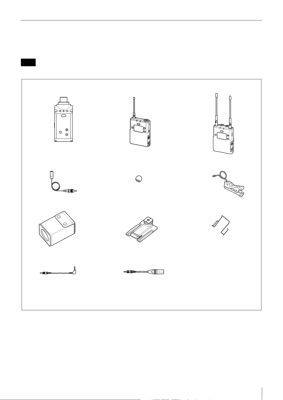
UWP-D16
The UWP-D16 consists of a plug-on transmitter (UTX-P03), a body-pack transmitter (UTX-B03), a portable diversity
tuner (URX-P03), and their accessories. When used in conjunction with a compact camcorder, a mobile system for ENG
(Electronic News Gathering) or EFP (Electronic Field Production) applications can be constructed.
Note
The UWP-D16 model is not available in China.
Plug-on transmitter
(UTX-P03) (1)
Supplied accessories
Omni-directional lavalier microphone (1)
Soft case (1)
Body-pack transmitter
(UTX-B03) (1)
Wind screen (1)
Shoe mount adapter (1)
Portable diversity tuner
(URX-P03) (1)
Holder clip (1)
Belt clip (2)
Stereo mini plug-BMP
conversion cable (1)
Before Use (1)
Quick Start Guide (1)
CD-ROM (1)
Warranty card (1) (North American and Korean models only)
XLR-BMP conversion output cable for the
URX-P03 (1)
Configuration of the Packages
5

Models available separately
The transmitter and tuner in each package are available
for purchase separately. The components provided with
each product are given below.
UTX-B03
• Body-pack transmitter (UTX-B03) (1)
• Omni-directional lavalier microphone (1)
• Wind screen (1)
• Holder clip (1)
• Belt clip (1)
• Battery case (1) (Chinese model only)
• Before Use (1)
•CD-ROM (1)
• Warranty card (1) (North American and Korean models
only)
UTX-M03
• Hand-held microphone (UTX-M03) (1)
• Microphone holder (1)
• Before Use (1)
•CD-ROM (1)
• Warranty card (1) (North American and Korean models
only)
UTX-P03
Note
The UTX-P03 model is not available in China.
• Plug-on transmitter (UTX-P03) (1)
• Soft case (1)
• Before Use (1)
•CD-ROM (1)
• Warranty card (1) (North American and Korean models
only)
URX-P03
• Portable diversity tuner (URX-P03) (1)
• Shoe mount adapter (1)
• Belt clip (1)
• XLR-BMP conversion output cable for the URX-P03
(1)
• Stereo mini plug-BMP conversion cable (1)
• Battery case (1) (Chinese model only)
• Before Use (1)
•CD-ROM (1)
• Warranty card (1) (North American and Korean models
only)
Configuration of the Packages
6

Features
The UWP-D11/D12/D16 (UWP-D series) Wireless
Microphone Packages comprise a transmitter (body-pack
transmitter (UTX-B03), hand-held microphone
(UTX-M03), or plug-on transmitter (UTX-P03)) and a
receiver (portable diversity tuner (URX-P03)). In
combination with a compact camcorder or
interchangeable-lens digital camera, the packages can be
used for various purposes, such as ENG (Electronic News
Gathering), EFP (Electronic Field Production), sports
events, and weddings.
They are equipped with a DSP for transmission of highquality sound using digital compander processing. They
can be used in combination with current Sony analog
wireless microphone systems (UWP series, WRT series,
WRR series, WRU series) by switching the compander
mode.
The frequency and compander mode set on the tuner can
be sent to the transmitter using an infrared
communications link. Used in combination with the Clear
Channel Scan function of the tuner, this greatly reduces
the time required to set channels.
The contents of each package are described below.
UWP-D11
Body-pack transmitter (UTX-B03)
This transmitter is a lightweight, compact transmitter that
employs a crystal-controlled PLL synthesizer. It is
equipped with a muting function and a BMP-type
microphone input connector. The RF power output can be
switched between high and low. It is also equipped with a
MIC/LINE input switching function to support a variety
of input levels.
Portable diversity tuner (URX-P03)
This tuner employs a true diversity method featuring little
signal dropout and an angle-adjustable antenna. It comes
with an adapter for mounting on a compact camcorder
(HXR-NX3, etc.). It also features a Clear Channel Scan
function to search for available channels automatically.
UWP-D12
Hand-held microphone (UTX-M03)
This microphone features a robust, metallic body. It has a
muting function and attenuator adjustment function to
support a wide audio input level range.
It can be used in diverse applications simply by changing
the microphone capsule. It has a built-in antenna.
* Microphone unit mounting dimensions: 31.3 mm
diameter, 1.0 mm pitch
Portable diversity tuner (URX-P03)
This tuner employs a true diversity method featuring little
signal dropout and an angle-adjustable antenna. It comes
with an adapter for mounting on a compact camcorder
(HXR-NX3, etc.). It also features a Clear Channel Scan
function to search for available channels automatically.
UWP-D16
Plug-on transmitter (UTX-P03)
This transmitter is a lightweight, compact plug-on type
transmitter that employs a crystal-controlled PLL
synthesizer. It has a muting function and an XLR-type
microphone input connector that can supply +48 V power
for connecting a wide range of microphones. It is also
equipped with a MIC/LINE switching function to support
a variety of input levels.
Body-pack transmitter (UTX-B03)
This transmitter is a lightweight, compact transmitter that
employs a crystal-controlled PLL synthesizer. It is
equipped with a muting function and a BMP-type
microphone input connector. The RF power output can be
switched between high and low. It is also equipped with a
MIC/LINE input switching function to support a variety
of input levels.
Portable diversity tuner (URX-P03)
This tuner employs a true diversity method featuring little
signal dropout and an angle-adjustable antenna. It comes
with an adapter for mounting on a compact camcorder
(HXR-NX3, etc.). It also features a Clear Channel Scan
function to search for available channels automatically.
Features
7

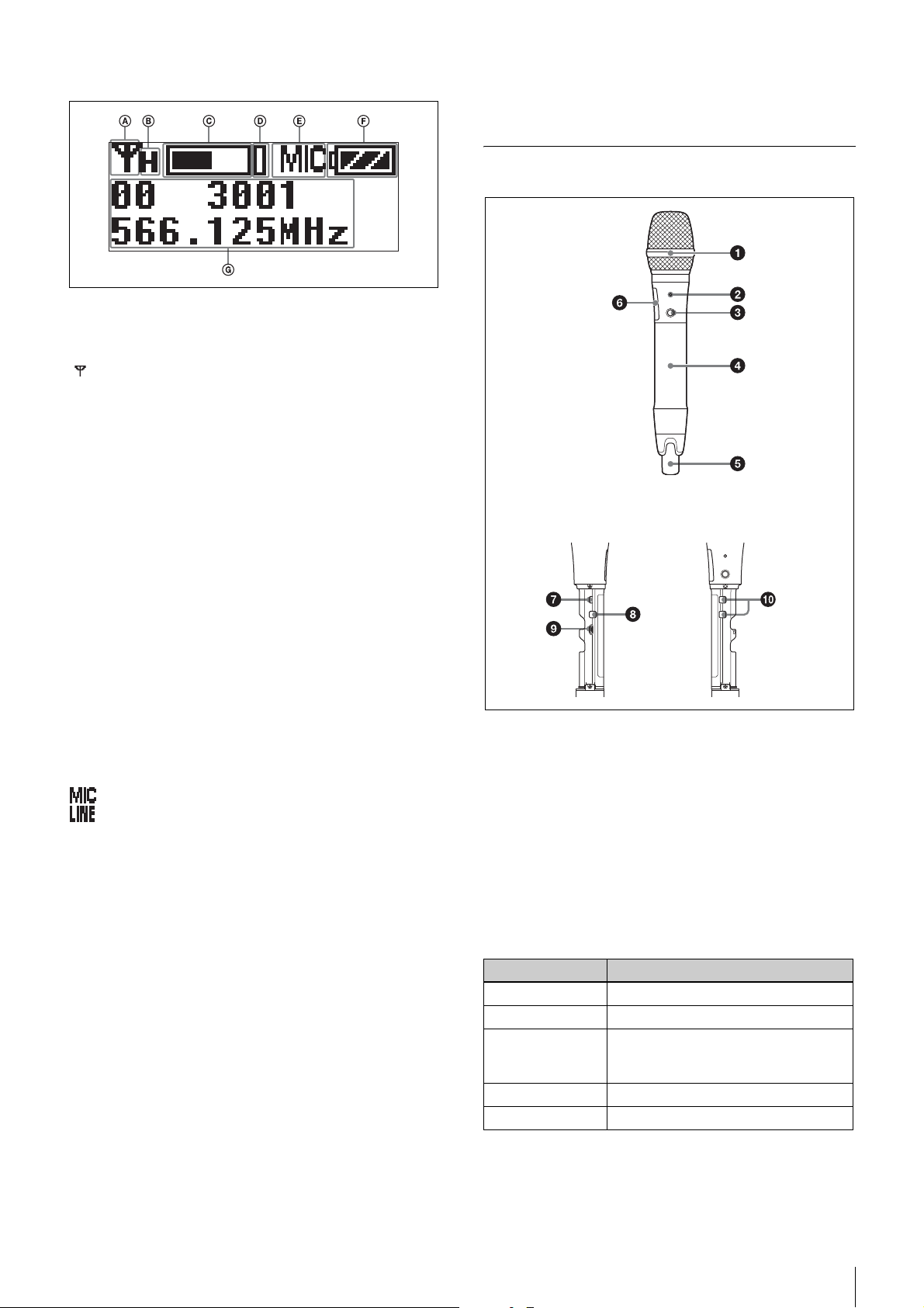
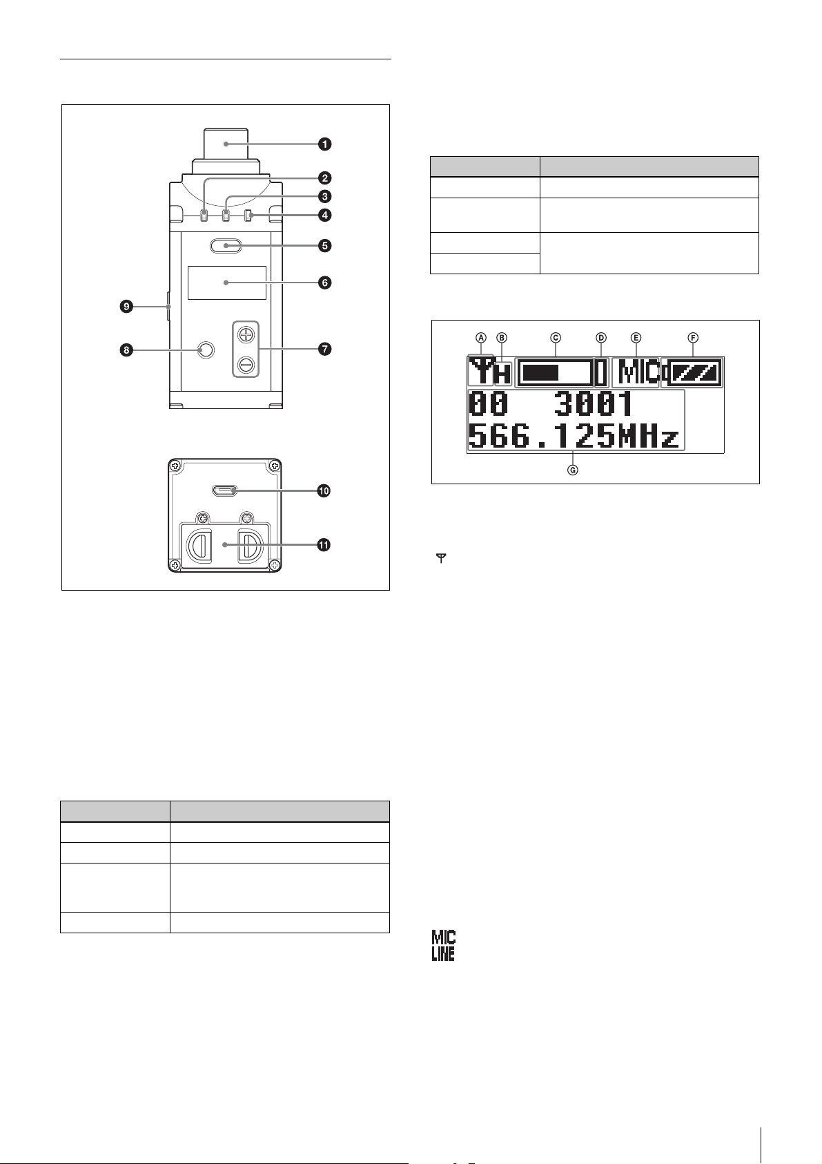
Name and Function of Parts
Body-pack transmitter (UTX-B03)
a Antenna
b POWER indicator
Displays the battery level and charging status.
Notes
• When the audio input level is set to MIC, a voltage for
the lavalier microphone power supply is applied to the
audio input connector. Special electrical wiring is used
inside the audio input connector for this purpose.
• If a lavalier microphone other than the one supplied is
connected, the proper performance may not be
obtained.
e POWER/MUTING button
Turns the power on/off. You also use this button to turn
the muting function on/off.
Function Operation
Supply ON Press button for one second or longer
Supply OFF Press button until the indicator turns
off
Muting ON Press button
Muting OFF
f USB connector (Micro B type)
Connect to a commercially available USB portable power
supply.
When a USB portable power supply is connected while
the power is turned on, the unit automatically operates
with power supplied by the USB portable power supply.
When a USB portable power supply is connected while
nickel metal hydride batteries are inserted and the power
is turned off, the batteries are charged by the USB
portable power supply.
Note
Indicator display Status
On (green) Sufficient battery level
Flashing (green) Battery is getting low
On (orange) Charging (when nickel metal hydride
rechargeable batteries are inserted
and power is turned off)
Off Power is off or battery is empty
c AUDIO (audio input level) indicator
Turns on or off according to the audio input level as
follows.
On (red): Audio input level is too high. If the sound is
distorted, adjust the attenuation level to decrease the
audio input level (page 27).
On (green): Audio input level is appropriate.
Off: There is no audio input or the input level is too low.
Flashing (orange): Audio is muted (i.e., disabled).
d Audio input connector (BMP type)
Connect to the supplied lavalier microphone.
Alkaline batteries and lithium batteries cannot be
recharged.
g Battery compartment
Accepts two AA batteries (alkaline, nickel metal hydride,
or lithium batteries).
For details on how to insert batteries, see “Power
Supply” (page 14).
h + or – button
Selects functions or values shown on the display.
Name and Function of Parts
8
i Display section
A RF transmission indicator
Displays the current transmission status.
: Transmitting
– : Transmission stopped
B RF transmission power indicator
Indicates the current transmission power setting. You can
change the setting with the RF transmission power setting
function.
For details on the RF transmission power setting
function, see “Setting the transmit output level (RF
POWER)” (page 27).
k Infrared detector
Receives the frequency and compander mode set on the
tuner.
Hand-held microphone (UTX-M03)
Inside the grip
C Audio input level meter
Displays the audio input level.
D Peak indicator
Lights up when the signal is 3 dB below the level at which
distortion begins as a warning of excessive input level.
E Input level indicator
Displays the input level status.
: Microphone input
: Line input
F Battery level indicator
Displays the battery level. Displays “EXT” when power
is supplied from the USB connector.
For details, see “Battery level indicator” (page 15).
G Menu display section
Displays various functions. Press the + or – button to
switch functions.
For details, see “Configuration menu” (page 23).
j SET button
Adjusts displayed function settings and enters the
displayed value.
Holding down the SET button while turning on the power
turns the transmitter on without transmitting a signal
(transmission stopped mode).
a Microphone unit
The standard-equipped microphone unit can be
interchanged with another microphone unit having a
diameter of 31.3 mm and a pitch of 1.0 mm.
For details on attaching and removing the microphone
unit, see “Replacing the microphone unit” (page 17).
b POWER indicator
Displays the battery level, charging status, and audio
muting (i.e., audio enabled or disabled) status.
Indicator display Status
On (green) Sufficient battery level
Flashing (green) Battery is getting low
On (orange) Charging (when nickel metal hydride
rechargeable batteries are inserted
and power is turned off)
Off Power is off or battery is empty
Flashing (orange) Audio is muted (i.e., disabled)
Name and Function of Parts
9
c POWER/MUTING button
Turns the power on/off. You also use this button to turn
the muting function on/off.
Function Operation
Supply ON Press button for one second or longer
Supply OFF Press button until the indicator turns
off
Muting ON Press button
Muting OFF
E Battery level indicator
Displays the battery level.
For details, see “Battery level indicator” (page 15).
F Menu display section
Displays various functions. Press the + or – button to
switch functions.
For details, see “Configuration menu” (page 23).
d Battery compartment
Accepts two AA batteries (alkaline, nickel metal hydride,
or lithium batteries).
For details on how to insert batteries, see “Power
Supply” (page 14).
e Antenna section
f Display section
A RF transmission indicator
Displays the current transmission status.
g Infrared detector
Receives the frequency and compander mode set on the
tuner.
h SET button
Adjusts displayed function settings and enters the
displayed value.
Holding down the SET button while turning on the power
turns the transmitter on without transmitting a signal
(transmission stopped mode).
i USB connector (Micro B type)
Connect to a commercially available USB portable power
supply.
When a USB portable power supply is connected while
nickel metal hydride batteries are inserted and the power
is turned off, the batteries are charged by the USB
portable power supply.
Note
Alkaline batteries and lithium batteries cannot be
recharged. Also, power cannot be supplied from a USB
portable power supply.
: Transmitting
– : Transmission stopped
B RF transmission power indicator
Indicates the current transmission power setting. You can
change the setting with the RF transmission power setting
function.
For details on the RF transmission power setting
function, see “Setting the transmit output level (RF
POWER)” (page 27).
C Audio input level meter
Displays the audio input level.
D Peak indicator
Lights up when the signal is 3 dB below the level at which
distortion begins as a warning of excessive input level.
j + or – button
Selects functions or values shown on the display.
Name and Function of Parts
10
Plug-on transmitter (UTX-P03)
Front
Bottom
Flashing (orange): Audio is muted (i.e., disabled).
e POWER/MUTING button
Turns the power on/off. You also use this button to turn
the muting function on/off.
Function Operation
Supply ON Press button for one second or longer
Supply OFF Press button until the indicator turns
off
Muting ON Press button
Muting OFF
f Display section
a Audio input connector (XLR type)
Connect to a microphone or the line output of an audio
mixer or other device.
b +48V (+48 V supply) indicator
Lights up when the unit is set to LINE input and is
supplying power to the connected microphone.
c POWER indicator
Displays the battery level and charging status.
Indicator display Status
On (green) Sufficient battery level
Flashing (green) Battery is getting low
On (orange) Charging (when nickel metal hydride
rechargeable batteries are inserted
and power is turned off)
Off Power is off or battery is empty
d AUDIO (audio input level) indicator
Turns on or off according to the audio input level as
follows.
On (red): Audio input level is too high. If the sound is
distorted, adjust the attenuation level to decrease the
audio input level (page 27).
On (green): Audio input level is appropriate.
Off: There is no audio input or input level is too low.
A RF transmission indicator
Displays the current transmission status.
: Transmitting
– : Transmission stopped
B RF transmission power indicator
Indicates the current transmission power setting. You can
change the setting with the RF transmission power setting
function.
For details on the RF transmission power setting
function, see “Setting the transmit output level (RF
POWER)” (page 27).
C Audio input level meter
Displays the audio input level.
D Peak indicator
Lights up when the signal is 3 dB below the level at which
distortion begins as a warning of excessive input level.
E Input level indicator
Displays the input level status.
: Microphone input
: Line input
F Battery level indicator
Displays the battery level. Displays “EXT” when power
is supplied from the USB connector.
For details, see “Battery level indicator” (page 15).
Name and Function of Parts
11
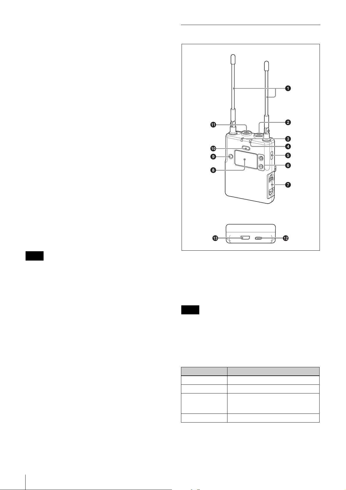
G Menu display section
Displays various functions. Press the + or – button to
switch functions.
For details, see “Configuration menu” (page 23).
g + or – button
Selects functions or values shown on the display.
h SET button
Adjusts displayed function settings and enters the
displayed value.
Holding down the SET button while turning on the power
turns the transmitter on without sending a signal
(transmission stopped mode).
i Infrared detector
Receives the frequency and compander mode set on the
tuner.
j USB connector (Micro B type)
Connect to a commercially available USB portable power
supply.
When a USB portable power supply is connected while
the power is turned on, the unit automatically operates
with power supplied by the USB portable power supply.
When a USB portable power supply is connected while
nickel metal hydride batteries are inserted and the power
is turned off, the batteries are charged by the USB
portable power supply.
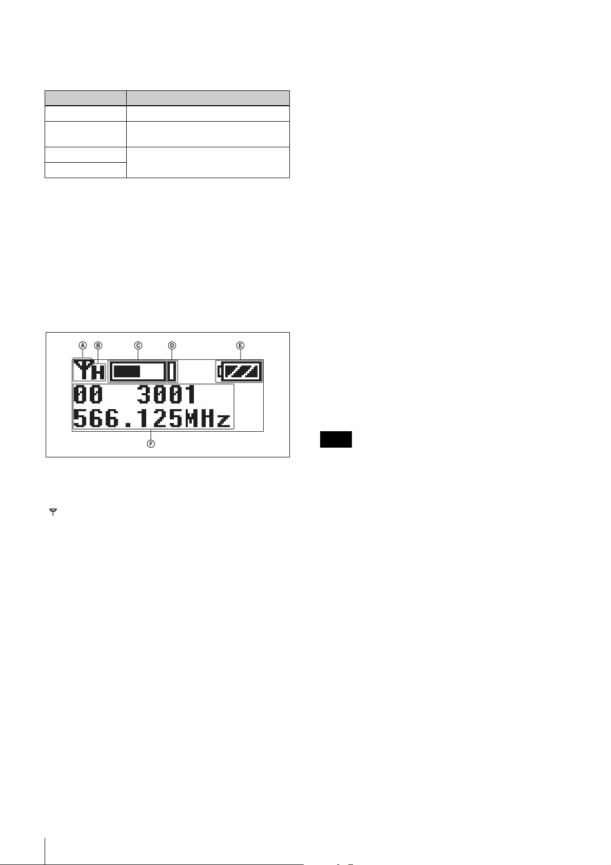
Portable diversity tuner (URX-P03)
Front
Bottom
Note
Alkaline batteries and lithium batteries cannot be
recharged.
k Battery compartment
Accepts two AA batteries (alkaline, nickel metal hydride,
or lithium batteries).
For details on how to insert batteries, see “Power
Supply” (page 14).
a Antenna
b PHONES (monitor) connector (3.5-mm
diameter, stereo mini jack)
Connect to headphones to monitor the audio output.
Note
Do not connect headphones with a monaural mini jack.
This may short-circuit the headphone outputs, resulting in
distorted sound output.
c POWER indicator
Displays the battery level and charging status.
Indicator display Status
On (green) Sufficient battery level
Flashing (green) Battery is getting low
On (orange) Charging (when nickel metal hydride
rechargeable batteries are inserted
and power is turned off)
Off Power is off or battery is empty
Name and Function of Parts
12
 Loading...