


 Loading...
Sony UWP-D26, UWP-D21, UTX-P40, UTX-M40, UWP-D22 User Manual
...5-009-934-11 (1)
Wireless Microphone
Package
Operating Instructions
Before operating the unit, please read this manual thoroughly and retain it for future reference.
UWP-D21/D22/D26
UTX-B40
UTX-M40
UTX-P40
URX-P40
© 2019 Sony Corporation

Table of Contents |
|
Configuration of the Packages .................. |
3 |
UWP-D21 ..................................................... |
3 |
UWP-D22 ..................................................... |
4 |
UWP-D26 ..................................................... |
5 |
Models available separately.......................... |
6 |
Features ....................................................... |
7 |
UWP-D21 ..................................................... |
7 |
UWP-D22 ..................................................... |
7 |
UWP-D26 ..................................................... |
7 |
Name and Function of Parts....................... |
8 |
Body-pack transmitter (UTX-B40)............... |
8 |
Hand-held microphone (UTX-M40)............. |
9 |
Plug-on transmitter (UTX-P40).................. |
11 |
Portable diversity tuner (URX-P40) ........... |
12 |
Power Supply............................................. |
14 |
Inserting the batteries.................................. |
14 |
Supplying power from a USB connector.... |
16 |
Attaching Accessories.............................. |
17 |
Attaching accessories to the body-pack |
|
transmitter (UTX-B40)...................... |
17 |
Attaching accessories to the hand-held |
|
microphone (UTX-M40)................... |
18 |
Attaching accessories to the plug-on |
|
transmitter (UTX-P40) ...................... |
18 |
Attaching accessories to the portable diversity |
|
tuner (URX-P40) ............................... |
18 |
Operation ................................................... |
19 |
If noise is generated .................................... |
20 |
Tuner Settings ........................................... |
20 |
Menu structure and operation ..................... |
20 |
Setting the receive channel ......................... |
21 |
Searching for available channels within a |
|
group (Clear Channel Scan) .............. |
21 |
Searching for active channels within a group |
|
(Active Channel Scan) ...................... |
22 |
Adjusting the monitor audio level .............. |
22 |
Configuration menu .................................... |
23 |
Transmitter Settings ................................. |
26 |
Menu structure and operation ..................... |
26 |
Setting the transmit channel........................ |
27 |
Configuration menu .................................... |
28 |
System Configuration Example ............... |
32 |
Error Messages ......................................... |
33 |
Troubleshooting........................................ |
34 |
Important Notes on Use............................ |
36 |
Usage and storage ....................................... |
36 |
Cleaning...................................................... |
36 |
Specifications............................................ |
37 |
Transmitter (UTX-B40/M40/P40).............. |
37 |
Tuner........................................................... |
39 |
2
Configuration of the Packages
This manual is for the UWP-D21/D22/D26 Wireless Microphone Packages. The contents of each package are described below.
Note
Some of the packages may not be available in certain countries or areas. In addition, the U90 model can only be used in the USA.
The use of U90 transmitters requires a license and is subject to restrictions on frequency selection and channel spacing. For details, consult your Sony dealer.
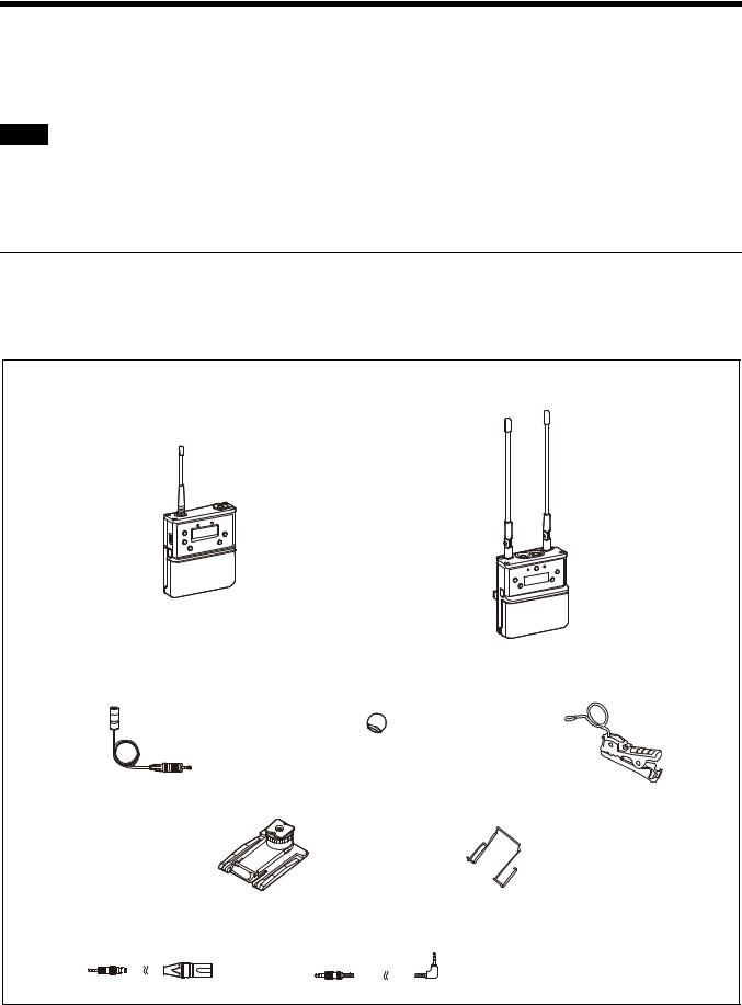
UWP-D21
The package consists of a body-pack transmitter (UTX-B40), a portable diversity tuner (URX-P40), and their accessories. When used in conjunction with a compact camcorder, a mobile system for ENG (Electronic News Gathering) or EFP (Electronic Field Production) applications can be constructed.
Body-pack transmitter |
Portable diversity tuner |
(UTX-B40) (1) |
(URX-P40) (1) |
Supplied accessories
Omni-directional lavalier microphone (1) |
Wind screen (1) |
Holder clip (1) |
Shoe mount adaptor (1) |
Belt clip (2) |
XLR-BMP conversion output |
Stereo mini plug-BMP conversion cable (1) |
||||||||||||
cable for the URX-P40 (1) |
|
|
|
|
|
|
|||||||
|
|
|
|
|
|
|
|
|
|
|
|
|
|
Before Use (1) Quick Start Guide (1) CD-ROM (1)
Warranty card (1) (UC, U, LA, KR models only)
3

UWP-D22
The package consists of a hand-held microphone (UTX-M40), a portable diversity tuner (URX-P40), and their accessories. When used in conjunction with a compact camcorder, a mobile system for ENG (Electronic News Gathering) or EFP (Electronic Field Production) applications can be constructed.
Hand-held microphone |
Portable diversity tuner |
||||||||||
(UTX-M40) (1) |
(URX-P40) (1) |
||||||||||
|
|
|
|
|
|
|
|
|
|
|
|
|
|
|
|
|
|
|
|
|
|
|
|
|
|
|
|
|
|
|
|
|
|
|
|
|
|
|
|
|
|
|
|
|
|
|
|
|
|
|
|
|
|
|
|
|
|
|
|
|
|
|
|
|
|
|
|
|
|
|
|
|
|
|
|
|
|
|
|
|
|
|
|
|
|
|
|
|
|
|
|
|
|
|
|
Supplied accessories
Microphone holder (1) |
Belt clip (1) |
Shoe mount adaptor (1) |
XLR-BMP conversion output |
Stereo mini plug-BMP conversion cable (1) |
Before Use (1) |
cable for the URX-P40 (1) |
|
Quick Start Guide (1) |
|
|
CD-ROM (1) |
|
|
Warranty card (1) (UC, U, LA, KR |
|
|
models only) |
4
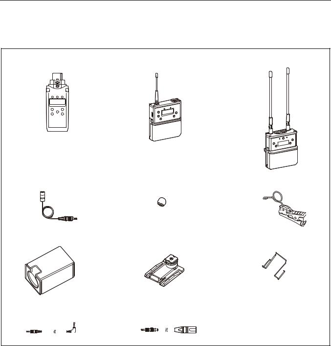
UWP-D26
The UWP-D26 consists of a plug-on transmitter (UTX-P40), a body-pack transmitter (UTX-B40), a portable diversity tuner (URX-P40), and their accessories. When used in conjunction with a compact camcorder, a mobile system for ENG (Electronic News Gathering) or EFP (Electronic Field Production) applications can be constructed.
Plug-on transmitter |
Body-pack transmitter |
Portable diversity tuner |
|||||||||||||||||
(UTX-P40) (1) |
(UTX-B40) (1) |
(URX-P40) (1) |
|||||||||||||||||
|
|
|
|
|
|
|
|
|
|
|
|
|
|
|
|
|
|
|
|
|
|
|
|
|
|
|
|
|
|
|
|
|
|
|
|
|
|
|
|
|
|
|
|
|
|
|
|
|
|
|
|
|
|
|
|
|
|
|
|
|
|
|
|
|
|
|
|
|
|
|
|
|
|
|
|
|
|
|
|
|
|
|
|
|
|
|
|
|
|
|
|
|
|
|
|
|
|
|
|
|
|
|
|
|
|
|
|
|
|
|
|
|
|
|
|
|
|
|
|
|
|
|
|
|
|
|
|
|
|
|
|
|
|
|
|
|
|
|
|
|
|
|
|
|
|
|
|
|
|
|
|
|
|
|
|
|
|
|
|
|
|
|
|
|
|
|
|
|
|
|
|
|
|
|
|
|
|
|
|
|
|
|
|
|
|
|
|
|
|
|
|
|
|
|
|
|
|
|
|
Supplied accessories
Omni-directional lavalier microphone (1) |
Wind screen (1) |
Holder clip (1) |
Soft case (1) |
Shoe mount adaptor (1) |
Belt clip (2) |
Stereo mini plug-BMP |
XLR-BMP conversion output cable for the |
|||||||||
conversion cable (1) |
URX-P40 (1) |
|||||||||
|
|
|
|
|
|
|
|
|
|
|
Before Use (1) Quick Start Guide (1) CD-ROM (1)
Warranty card (1) (UC, U, LA, KR models only)
5

Models available separately
The transmitter and tuner in each package are available for purchase separately. The components provided with each product are given below.
UTX-B40
•Body-pack transmitter (UTX-B40) (1)
•Omni-directional lavalier microphone (1)
•Wind screen (1)
•Holder clip (1)
•Belt clip (1)
•Before Use (1)
•CD-ROM (1)
•Warranty card (1) (UC, U, LA, KR models only)
UTX-M40
•Hand-held microphone (UTX-M40) (1)
•Microphone holder (1)
•Before Use (1)
•CD-ROM (1)
•Warranty card (1) (UC, U, LA, KR models only)
UTX-P40
•Plug-on transmitter (UTX-P40) (1)
•Soft case (1)
•Before Use (1)
•CD-ROM (1)
•Warranty card (1) (UC, U, LA, KR models only)
URX-P40
•Portable diversity tuner (URX-P40) (1)
•Shoe mount adaptor (1)
•Belt clip (1)
•XLR-BMP conversion output cable for the URX-P40
(1)
•Stereo mini plug-BMP conversion cable (1)
•Before Use (1)
•CD-ROM (1)
•Warranty card (1) (UC, U, LA, KR models only)
6

Features
The UWP-D21/D22/D26 (UWP-D series) Wireless Microphone Packages comprise a transmitter (body-pack transmitter (UTX-B40), hand-held microphone (UTX-M40), or plug-on transmitter (UTX-P40)) and a receiver (portable diversity tuner (URX-P40)). In combination with a compact camcorder or interchangeable-lens digital camera, the packages can be used for various purposes, such as ENG (Electronic News Gathering), EFP (Electronic Field Production), sports events, and weddings.
The features of each package are described below.
UWP-D21
•High quality sound with Sony Digital Audio Processing
•“NFC SYNC” function for quick and easy secure channel setting
•True diversity for stable signal reception
•Auto gain mode volume control
•+15 dB gain volume boost mode for off-mic audio
•Line input available
•Channel memory function for fast switching between two receiver frequencies
•Transmitter frequency sent to receiver
•Headphone output for monitoring
•Monitor mode for using a receiver as an ear monitor
•Variable muting function
•Compatibility with Sony WL-800/UWP/UWP-D series
•Output level control for receiver
•High visibility OLED display for indoor/outdoor use
•USB for power supply
•Digital audio interface support using SMAD-P5 multiinterface shoe-mount adaptor (option)*
*For details on cameras that support this function, visit the Sony website.
UWP-D22
•High quality sound with Sony Digital Audio Processing
•“NFC SYNC” function for quick and easy secure channel setting
•True diversity for stable signal reception
•Interchangeable head for wide choice of microphone capsule
•Auto gain mode volume control
•+15 dB gain volume boost mode for off-mic audio
•Channel memory function for fast switching between two receiver frequencies
•Transmitter frequency sent to receiver
•Headphone output for monitoring
•Monitor mode for using a receiver as an ear monitor
•Variable muting function
•Compatibility with Sony WL-800/UWP/UWP-D series
•Output level control for receiver
•High visibility OLED display for indoor/outdoor use
•USB connector for power supply (URX-P40 only)
•Digital audio interface support using SMAD-P5 multiinterface shoe-mount adaptor (option)*
*For details on cameras that support this function, visit the Sony website.
UWP-D26
•High quality sound with Sony Digital Audio Processing
•“NFC SYNC” function for quick and easy secure channel setting
•True diversity for stable signal reception
•Auto gain mode volume control
•+15 dB gain volume boost mode for off-mic audio
•Line input available
•+48V power supply (plug-on transmitter)
•Channel memory function for fast switching between two receiver frequencies
•Transmitter frequency sent to receiver
•Headphone output for monitoring
•Monitor mode for using a receiver as an ear monitor
•Variable muting function
•Compatibility with Sony WL-800/UWP series
•Output level control for receiver
•High visibility OLED display for indoor/outdoor use
•USB for power supply
•Digital audio interface support using SMAD-P5 multiinterface shoe-mount adaptor (option)*
*For details on cameras that support this function, visit the Sony website.
7
Name and Function of
Parts
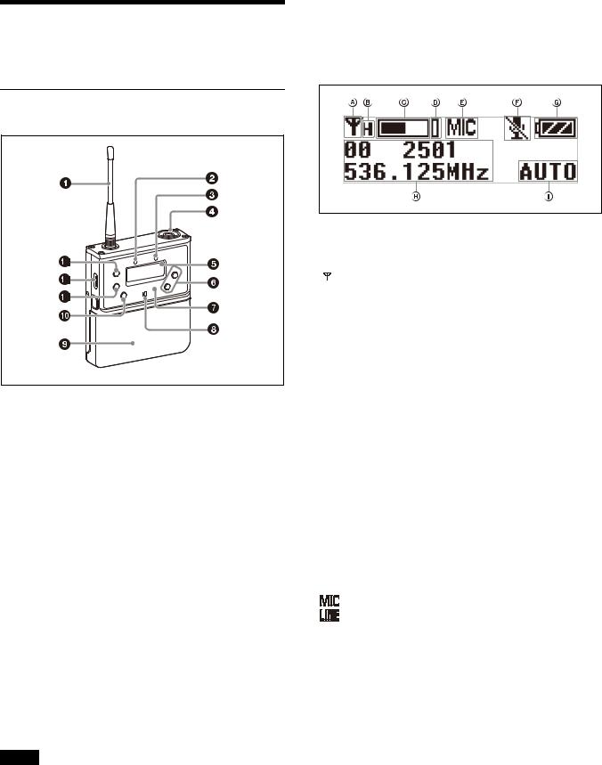
Body-pack transmitter (UTX-B40)
aAntenna
bPOWER indicator
Displays the battery level.
Indicator display |
Status |
On (green) |
Sufficient battery level |
|
|
Flashing (green) |
Battery is getting low |
|
|
Off |
Supply OFF |
|
|
cAUDIO (audio input level) indicator
Turns on or off according to the audio input level as follows.
On (red): Audio input level is too high. If the sound is distorted, adjust the attenuation level to decrease the audio input level (page 28).
On (green): Audio input level is appropriate.
Off: There is no audio input or the input level is too low. Flashing (orange): Audio is muted (i.e., disabled).
dAudio input connector (BMP type)
Connect to the supplied lavalier microphone.
Notes
•When the audio input level is set to MIC, a voltage for the lavalier microphone power supply is applied to the audio input connector. Special electrical wiring is used inside the audio input connector for this purpose.
•If a lavalier microphone other than the one supplied is connected, the proper performance may not be obtained.
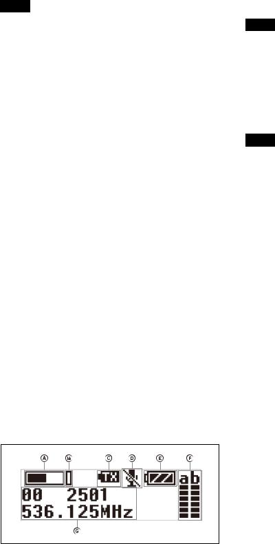
eDisplay section
ARF transmission indicator
Displays the current transmission status.
: Transmitting
– : Transmission stopped
BRF transmission power indicator
Indicates the current transmission power setting. You can change the setting with the RF transmission power setting function.
For details on the RF transmission power setting function, see “Setting the transmit output level (RF POWER)” (page 29).
CAudio input level meter
Displays the audio input level.
DPeak indicator
Lights up when the signal is 3 dB below the level at which distortion begins as a warning of excessive input level.
EInput level indicator
Displays the input level status.


 : Microphone input


 : Line input
FMuting status indicator
Displays an icon when the muting function is on.
For details about the muting function, see “Setting the operation of the audio muting function (MUTE SETTING) (UTX-B40/P40 only)” (page 29).
GBattery level indicator
Displays the battery level. “USB” is displayed when power is supplied from the USB connector.
For details, see “Battery level indicator” (page 16).
HMenu display section
Displays various functions. Press the + or – button to switch functions.
8
For details, see “Configuration menu” (page 23).
IGain mode indicator
Displays the gain mode setting.
For details, see “Setting the audio gain (GAIN MODE)” (page 28).
f+ or – button
Selects functions or values shown on the display.
gInfrared detector
Receives the frequency and compander mode set on the tuner.
hN-Mark
Receives the frequency and compander mode set on the tuner. It also notifies the tuner about the frequency and compander mode set on the transmitter.
iBattery compartment
Accepts two AA batteries (alkaline, nickel metal hydride, or lithium batteries).
For details on how to insert batteries, see “Power Supply” (page 14).
jMUTE button
Turns the muting function on/off. You can change the muting function on/off control method in the configuration menu.
For details about switching the muting function on/off, see “Setting the operation of the audio muting function (MUTE SETTING) (UTX-B40/P40 only)” (page 29).
kSET button
Adjusts displayed function settings and enters the displayed value.
Holding down the SET button while turning on the power turns the transmitter on without transmitting a signal (transmission stopped mode).
lUSB connector (Type C)
Connect to a commercially available USB portable power supply.
When a USB portable power supply is connected while the power is turned on, the unit automatically operates with power supplied by the USB portable power supply.
mPOWER button
Turns the power on/off.
Function |
Operation |
Supply ON |
Press button for one second or |
|
longer |
|
|
Supply OFF |
Press button until the indicator turns |
|
off |
|
|
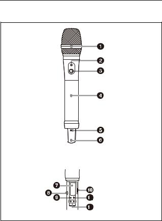
Hand-held microphone (UTX-M40)
Inside the grip
aMicrophone unit
The standard-equipped microphone unit can be interchanged with another microphone unit having a diameter of 31.3 mm and a pitch of 1.0 mm.
For details on attaching and removing the microphone unit, see “Replacing the microphone unit” (page 18).
bPOWER indicator
Displays the battery level and audio muting (i.e., audio enabled or disabled) status.
Indicator display |
Status |
On (green) |
Sufficient battery level |
|
|
Flashing (green) |
Battery is getting low |
|
|
Off |
Supply OFF |
|
|
Flashing (orange) |
Audio is muted (i.e., disabled) |
|
|
cPOWER/MUTE button
Turns the power on/off. You also use this button to turn the muting function on/off.
Function |
Operation |
Supply ON |
Press button for one second or |
|
longer |
|
|
Supply OFF |
Press button until the indicator turns |
|
off |
|
|
Muting ON |
Press button |
|
|
Muting OFF |
|
|
|
9
You can disable the power supply operation of the POWER/MUTE button and change the muting function on/off control method from the configuration menu.
For details, see “Setting the operation of the audio muting function (POWER/MUTE) (UTX-M40 only)” (page 29).
dBattery compartment
Accepts two AA batteries (alkaline, nickel metal hydride, or lithium batteries).
For details on how to insert batteries, see “Power Supply” (page 14).
eN-Mark
Receives the frequency and compander mode set on the tuner. It also notifies the tuner about the frequency and compander mode set on the transmitter.
fAntenna section
gDisplay section
ARF transmission indicator
Displays the current transmission status.
: Transmitting
– : Transmission stopped
BRF transmission power indicator
Indicates the current transmission power setting. You can change the setting with the RF transmission power setting function.
For details on the RF transmission power setting function, see “Setting the transmit output level (RF POWER)” (page 29).
CAudio input level meter
Displays the audio input level.
DPeak indicator
Lights up when the signal is 3 dB below the level at which distortion begins as a warning of excessive input level.
EMuting status indicator
Displays an icon when the muting function is on.
For details about the muting function, see “Setting the operation of the audio muting function (POWER/MUTE) (UTX-M40 only)” (page 29).
FBattery level indicator
Displays the battery level.
For details, see “Battery level indicator” (page 16).
GMenu display section
Displays various functions. Press the + or – button to switch functions.
For details, see “Configuration menu” (page 23).
HGain mode indicator
Displays the gain mode setting.
For details, see “Setting the audio gain (GAIN MODE)” (page 28).
hInfrared detector
Receives the frequency and compander mode set on the tuner.
iSET button
Adjusts displayed function settings and enters the displayed value.
Holding down the SET button while turning on the power turns the transmitter on without transmitting a signal (transmission stopped mode).
jUSB connector (Type C)
For use by service personnel.
kPOWER button
Turns the power on/off.
l+ or – button
Selects functions or values shown on the display.
10

Plug-on transmitter (UTX-P40)
Front
Bottom
aAudio input connector (XLR type)
Connect to a microphone or the line output of an audio mixer or other device.
b+48V (+48 V supply) indicator
Lights up when the unit is set to MIC input and is supplying power to the connected microphone.
cPOWER indicator
Displays the battery level.
Indicator display |
Status |
On (green) |
Sufficient battery level |
|
|
Flashing (green) |
Battery is getting low |
|
|
Off |
Supply OFF |
|
|
dAUDIO (audio input level) indicator
Turns on or off according to the audio input level as follows.
On (red): Audio input level is too high. If the sound is distorted, adjust the attenuation level to decrease the audio input level (page 28).
On (green): Audio input level is appropriate.
Off: There is no audio input or the input level is too low. Flashing (orange): Audio is muted (i.e., disabled).
eDisplay section
ARF transmission indicator
Displays the current transmission status.
: Transmitting
– : Transmission stopped
BRF transmission power indicator
Indicates the current transmission power setting. You can change the setting with the RF transmission power setting function.
For details on the RF transmission power setting function, see “Setting the transmit output level (RF POWER)” (page 29).
CAudio input level meter
Displays the audio input level.
DPeak indicator
Lights up when the signal is 3 dB below the level at which distortion begins as a warning of excessive input level.
EInput level indicator
Displays the input level status.


 : Microphone input


 : Line input
FMuting status indicator
Displays an icon when the muting function is on.
For details about the muting function, see “Setting the operation of the audio muting function (MUTE SETTING) (UTX-B40/P40 only)” (page 29).
GBattery level indicator
Displays the battery level. “USB” is displayed when power is supplied from the USB connector.
For details, see “Battery level indicator” (page 16).
HMenu display section
Displays various functions. Press the + or – button to switch functions.
For details, see “Configuration menu” (page 23).
11
IGain mode indicator
Displays the gain mode setting.
For details, see “Setting the audio gain (GAIN MODE)” (page 28).
f+ or – button
Selects functions or values shown on the display.
gInfrared detector
Receives the frequency and compander mode set on the tuner.
hN-Mark
Receives the frequency and compander mode set on the tuner. It also notifies the tuner about the frequency and compander mode set on the transmitter.
iMUTE button
Turns the muting function on/off. You can change the muting function on/off control method in the configuration menu.
For details about switching the muting function on/off, see “Setting the operation of the audio muting function (MUTE SETTING) (UTX-B40/P40 only)” (page 29).
jSET button
Adjusts displayed function settings and enters the displayed value.
Holding down the SET button while turning on the power turns the transmitter on without transmitting a signal (transmission stopped mode).
kPOWER button
Turns the power on/off.
Function |
Operation |
Supply ON |
Press button for one second or |
|
longer |
|
|
Supply OFF |
Press button until the indicator turns |
|
off |
|
|
lUSB connector (Type C)
Connect to a commercially available USB portable power supply.
When a USB portable power supply is connected while the power is turned on, the unit automatically operates with power supplied by the USB portable power supply.
mBattery compartment
Accepts two AA batteries (alkaline, nickel metal hydride, or lithium batteries).
For details on how to insert batteries, see “Power Supply” (page 14).
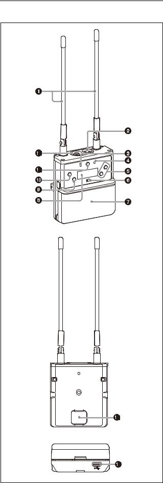
Portable diversity tuner (URX-P40)
Front
Rear
Bottom
12
aAntenna
bPHONES (monitor) connector (3.5 mm diameter, stereo mini jack)
Connect to headphones to monitor the audio output.
Note
Do not connect headphones with a monaural mini jack. This may short-circuit the headphone outputs, resulting in distorted sound output.
cPOWER indicator
Displays the battery level.
Indicator display |
Status |
On (green) |
Sufficient battery level |
|
|
Flashing (green) |
Battery is getting low |
|
|
Off |
Supply OFF |
|
|
dRF (radio frequency input) indicator
Displays the RF input level using the following colors. On (green): Input level is 25 dBµ or more.
On (red): Input level is 15 dBµ to 25 dBµ. Off: Input level is 15 dBµ or lower.
* 0 dBµ = 1 µVEMF
e+ or – button
Selects functions or values shown on the display.
fN-Mark
Sends the set frequency and compander mode to the transmitter. It also detects the tuner about the frequency and compander mode set on the transmitter.
gBattery compartment
Accepts two AA batteries (alkaline, nickel metal hydride, or lithium batteries).
For details on how to insert batteries, see “Power Supply” (page 14).
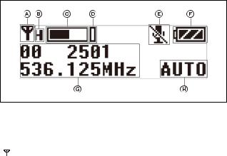
hDisplay section
AAudio input level meter
Displays the audio input level.
BPeak indicator
Lights up when the signal is 3 dB below the level at which distortion begins as a warning of excessive input level.
CTransmitter power warning indicator
Displays an icon when the remaining battery capacity of the transmitter being received is almost discharged.
Notes
•The icon is not displayed if the receive signal level is low.
•This function is enabled only when the transmitter is a UTX-B40/M40/P40.
DTransmitter muting status indicator
Displays an icon when the muting function of the transmitter being received is on.
Notes
•The icon is not displayed if the receive signal level is low.
•This function is enabled only when the transmitter is a UTX-B40/M40/P40.
EBattery level indicator
Displays the battery level. “USB” is displayed when power is supplied from the USB connector. “MI” is displayed when power is supplied from an SMAD-P5 (not supplied).
For details, see “Battery level indicator” (page 16).
FRF level (reception level) indicator
Indicates the current reception level.
GMenu display section
Displays various functions. Press the + or – button to switch functions.
For details, see “Configuration menu” (page 23).
i NFC SYNC (NFC communication) button
Press to start a channel scan and for NFC communication with the transmitter.
For details, see “Operation” (page 19).
jSET button
Adjusts displayed function settings and enters the displayed value.
Holding down the SET button while turning on the power turns the transmitter on without transmitting a signal (transmission stopped mode).
kPOWER button
Turns the power on/off.
13
Loading...