


 Loading...
|
TC-WE435 |
SERVICE MANUAL |
US Model |
Ver 1.1 2001. 05 |
Canadian Model |
|
AEP Model |
|
UK Model |
|
E Model |
|
Australian Model |
|
Chinese Model |
Dolby noise reduction extension manufactured under license from Dolby Laboratories Licensing Corporation.
HX Pro originated by Bang & Olufsen. “DOLBY”, the double-D symbol a and “HX PRO” are trademarks of Dolby Laboratories Licensing Corporation.
Model Name Using Similar Mechanism TC-WE425/WE525/WR681
DECK A TCM-230ASR3/HSR3
Transport Mechanism Type
DECK B TCM-230ASR4/HSR4
SPECIFICATIONS
— Continued on next page —
STEREO CASSETTE DECK
9-928-829 -12 |
Sony Corporation |
2001E0200-1 |
Personal Audio Company |
© 2001.5 |
Shinagawa Tec Service Manual Production Group |
– 1 –

SAFETY CHECK-OUT
After correcting the original service problem, perform the following safety checks before releasing the set to the customer:
Check the antenna terminals, metal trim, “metallized” knobs, screws, and all other exposed metal parts for AC leakage. Check leakage as described below.
LEAKAGE
The AC leakage from any exposed metal part to earth Ground and from all exposed metal parts to any exposed metal part having a return to chassis, must not exceed 0.5 mA (500 microampers). Leakage current can be measured by any one of three methods.
1. A commercial leakage tester, such as the Simpson 229 or RCA WT-540A. Follow the manufacturers’ instructions to use these instruments.
2. A battery-operated AC milliammeter. The Data Precision 245 digital multimeter is suitable for this job.
3. Measuring the voltage drop across a resistor by means of a VOM or battery-operated AC voltmeter. The “limit” indication is 0.75 V, so analog meters must have an accurate low-voltage scale. The Simpson 250 and Sanwa SH-63Trd are examples of a passive VOM that is suitable. Nearly all battery operated digital multimeters that have a 2V AC range are suitable. (See Fig. A)
To Exposed Metal
Parts on Set
AC 0.15µF  1.5kΩ
1.5kΩ  voltmeter
(0.75V)
Earth Ground
Fig. A. Using an AC voltmeter to check AC leakage.
SAFETY-RELATED COMPONENT WARNING!!
COMPONENTS IDENTIFIED BY MARK ! OR DOTTED LINE
WITH MARK ! ON THE SCHEMATIC DIAGRAMS AND IN
THE PARTS LIST ARE CRITICAL TO SAFE OPERATION.
REPLACE THESE COMPONENTS WITH SONY PARTS WHOSE
PART NUMBERS APPEAR AS SHOWN IN THIS MANUAL OR
IN SUPPLEMENTS PUBLISHED BY SONY.
ATTENTION AU COMPOSANT AYANT RAPPORT À LA SÉCURITÉ!!
LES COMPOSANTS IDENTIFIÉS PAR UNE MARQUE !SUR LES
DIAGRAMMES SCHÉMATIQUES ET LA LISTE DES PIÈCES SONT
CRITIQUES POUR LA SÉCURITÉ DE FONCTIONNEMENT. NE
REMPLACER CES COMPOSANTS QUE PAR DES PIÈCES SONY
DONT LES NUMÉROS SONT DONNÉS DANS CE MANUEL OU
DANS LES SUPPLÉMENTS PUBLIÉS PAR SONY.
– 2 –
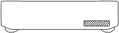
MODEL IDENTIFICATION
–Back panel–
Part No.
PARTS No. |
MODEL |
|
3-032-413-0¹ |
US model |
|
3-032-413-1¹ |
CND model |
|
3-032-413-2¹ |
AEP model |
|
3-032-413-3¹ |
UK model |
|
3-032-413-4¹ |
AUS model |
|
3-032-413-5¹ |
SP, MY model |
|
3-032-413-6¹ |
CH model |
|
• Abbreviation |
|
|
CND |
: Canadian model |
|
SP |
: Singapore model |
|
MY |
: Malaysia model |
|
AUS |
: Australian model |
|
CH |
: Chinese model |
|
TABLE OF CONTENTS |
|
1. GENERAL .......................................................................... |
4 |
2. DISASSEMBLY |
|
2-1. Case ...................................................................................... |
5 |
2-2. Front Panel Assembly ........................................................... |
5 |
2-3. Cassette Lid Assembly (Deck A/B) ...................................... |
6 |
2-4. Mechanism Deck Assembly (Deck A/B) .............................. |
6 |
2-5. Leaf SW (PB) Board (Deck A), |
|
Leaf SW (REC/PB) Board (Deck B) .................................... |
7 |
2-6. Pinch Lever (FWD)/(REV) Assembly (Deck A/B) ............... |
8 |
2-7. Flywheel (FWD)/(REV) Assembly (Deck A/B) ................... |
8 |
2-8. Mechanical Block Assembly (Deck A/B) ............................. |
9 |
2-9. Head Relay (PB) Board (Deck A), |
|
Head Relay (REC/PB) Board (Deck B) ................................ |
9 |
3. SERVICE MODE ............................................................ |
10 |
4. MECHANICAL ADJUSTMENTS ............................... |
11 |
5. ELECTRICAL ADJUSTMENTS ............................... |
11 |
6. DIAGRAMS |
|
6-1. Circuit Boards Location ...................................................... |
15 |
6-2. Printed Wiring Board – Main Section – .............................. |
17 |
6-3. Schematic Diagram – Main Section – (1/4) ........................ |
19 |
6-4. Schematic Diagram – Main Section – (2/4) ........................ |
21 |
6-5. Schematic Diagram – Main Section – (3/4) ........................ |
23 |
6-6. Schematic Diagram – Main Section – (4/4) ........................ |
25 |
6-7. Printed Wiring Board – Deck A Section – .......................... |
27 |
6-8. Schematic Diagram – Deck A Section – ............................. |
27 |
6-9. Printed Wiring Board – Deck B Section – .......................... |
28 |
6-10. Schematic Diagram – Deck B Section – ........................... |
28 |
6-11. Schematic Diagram – Display Section – ........................... |
29 |
6-12. Printed Wiring Board – Display Section – ....................... |
31 |
6-13. Schematic Diagram – Panel Section – .............................. |
33 |
6-14. Printed Wiring Board – Panel Section – ........................... |
35 |
6-15. Schematic Diagram – Power Section – ............................. |
37 |
6-16. Printed Wiring Board – Power Section – ......................... |
39 |
6-17. IC Pin Function ................................................................ |
41 |
7. EXPLODED VIEWS |
|
7-1. Case Section ........................................................................ |
43 |
7-2. Chassis Section ................................................................... |
44 |
7-3. Cassette Holder Section ...................................................... |
45 |
7-4. Front Panel Section ............................................................. |
46 |
7-5. Tape Mechanism Section |
|
(Deck A: TCM-230ASR3/HSR3) |
|
(Deck A: TCM-230ASR4/HSR4) ....................................... |
47 |
8. ELECTRICAL PARTS LIST ........................................ |
48 |
– 3 –
SECTION 1
GENERAL
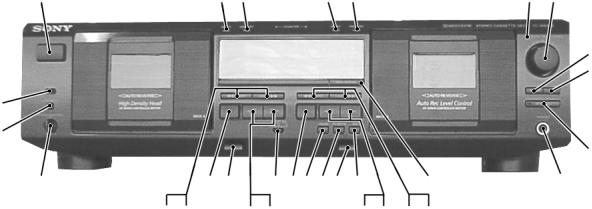
Front Panel
1 |
2 |
3 |
4 |
5 |
6 |
7 |
8
9
31
30
10
|
29 |
26 25 |
22 21201918 17 |
12 |
11 |
|
|
|
28 27 |
24 23 |
16 15 |
14 13 |
|
LOCATION OF PARTS AND CONTROLS |
|
|
|
|
||
1 |
Ubutton |
|
18 |
§(Eject) (Deck B) button |
|
|
2 |
RESET (Deck A) button |
|
19 |
REC MUTING Rbutton |
|
|
3 |
MEMORY (Deck A) button |
|
20 |
PAUSE Pbutton |
|
|
4 |
RESET (Deck B) button |
|
21 |
p(Deck B) button |
|
|
5 |
MEMORY (Deck B) button |
|
22 |
DOLBY NR OFF B/C switch |
|
|
6 |
AUTO REC LEVEL indicator |
|
23 |
·(Deck A) button |
|
|
7 |
REC LEVEL knob |
|
24 |
ª(Deck A) button |
|
|
8 |
FADER button |
|
25 |
§(Eject) (Deck A) button |
|
|
9 |
ARL button |
|
26 |
p(Deck A) button |
|
|
10 |
SYNCHRO button |
|
27 |
(AMS) )(Deck A) button |
|
|
11 |
PHONES jack |
|
28 |
0(AMS) (Deck A) button |
|
|
12 |
HIGH/NOMAL button |
|
29 |
PITCH CONTROL knob |
|
|
13 |
(AMS) )(Deck B) button |
|
30 |
PITCH CONTROL button |
|
|
14 |
0(AMS) (Deck B) button |
|
31 |
DIRECTION switch |
|
|
15 |
·(Deck B) button |
|
• AMS is the abbreviation for Automatic Music Sensor. |
|||
16 |
ª(Deck B) button |
|
||||
17 |
REC rbutton |
|
|
|
|
|
– 4 –
SECTION 2
DISASSEMBLY
Note : Follow the disassembly procedure in the numerical order given.
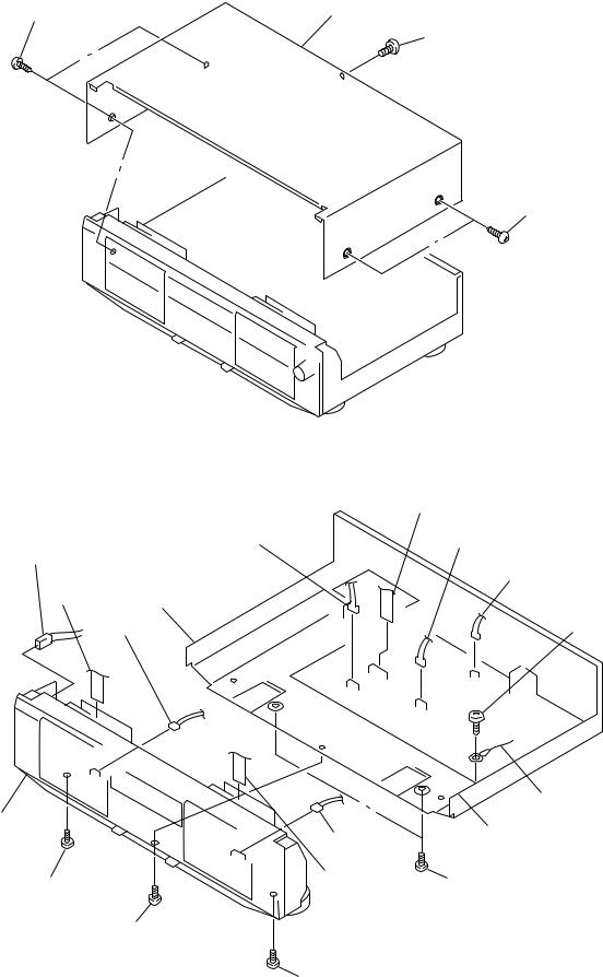
2-1. CASE
3 Two Screws |
4 Case |
|
|
(Case 3 TP2) |
1 Screw |
|
|
|
(BVTT 3x6) |
2 Two Screws
(Case 3 TP2)
2-2. FRONT PANEL ASSEMBLY
|
1 CN5802 |
2 CN807 |
3 CN803 |
!¡ CN002 |
|
|
4 CNA806 |
5 Flat type wire !§ Claw |
|
(Deck A) |
|
9 CN1002 |
7 Screw |
(BVTP 3x8)
8Wire
!• Front panel assy
|
0 CN1003 |
!° Claw |
|
|
|
||
!¢ Screw |
6 Flat type wire |
!¶ Two screws |
|
(Deck B) |
|||
(BVTP 3x8) |
(BVTT 3x6) |
||
|
|||
|
!£ Screw |
|
|
|
(BVTP 3x8) |
|
|
|
!™ Screw |
|
|
|
(BVTP 3x8) |
|
– 5 –

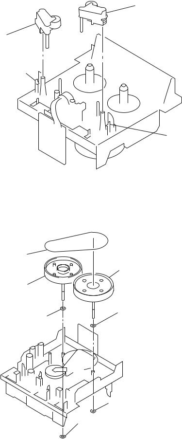
2-3. CASSETTE LID ASSEMBLY (DECK A/B)
1 Push the EJECT button.
3 Cassette lid assy
2 Four claws
2-4. MECHANISM DECK ASSEMBLY (DECK A/B)
3 Mechanism deck assy
1 Two screws (BVTP 2.6x8)
2 Two screws (BVTP 2.6x8)
– 6 –
2-5. LEAF SW (PB) BOARD (DECK A), LEAF SW (REC/PB) BOARD (DECK B)
1 Two screws (PS 2.6x6)
5 Screw |
2 Capstan motor assy |
(BVTT 2x4) |
|
4 Screw |
|
|
|
(BVTT 2x4) |
7 LEAF SW (PB) board |
a |
3 Wires |
(Deck A) |
b |
|
|
|
|
LEAF SW (REC/PB) board |
|
8 Belt (capstan) |
(Deck B) |
|
|
|
When installing, |
|
Claws |
pull the belt (capstan) |
|
put around claws. |
||
|
b a
6 Claws
– 7 –
2-6. PINCH LEVER (FWD)/(REV) ASSEMBLY (DECK A/B)
4 Pinch lever (FWD) assy
2 Pinch lever (REV) assy
1 Claw
3 Claw
2-7. FLYWHEEL (FWD)/(REV) ASSEMBLY (DECK A/B)
1 Belt (FR2)
3 Flywheel (FWD) assy
6 Flywheel (REV) assy
4 Washer
7 Washer
2 Stopper washer
5 Stopper washer
– 8 –
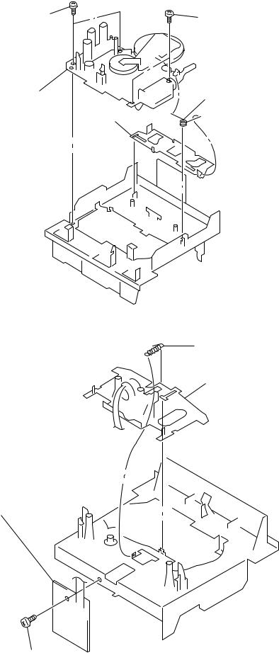
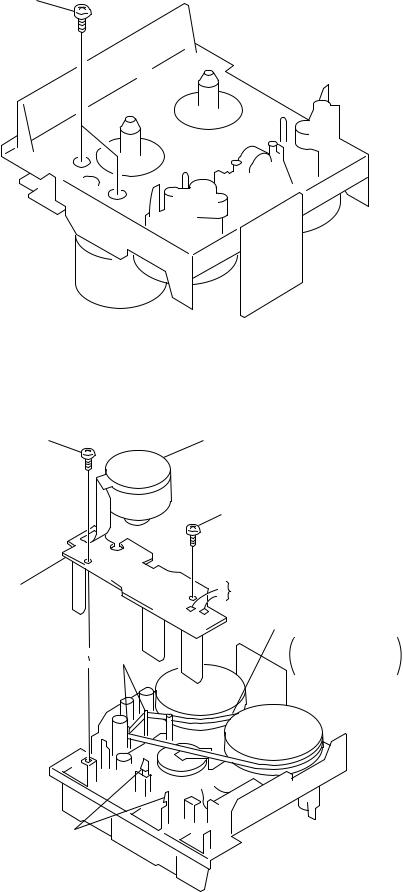
2-8. MECHANICAL BLOCK ASSEMBLY (DECK A/B)
3 Two screws |
2 Two screws |
(BVTT 2x3.5) |
(BVTT 2x3.5) |
4 Mechanical block assy |
1 Torsion spring |
5 Reverse slider
2-9. HEAD RELAY (PB) BOARD (DECK A), HEAD RELAY (REC/PB) BOARD (DECK B)
3 Tension spring (HEAD)
4 Head deck assy
2HEAD RELAY (PB) board
(Deck A)
HEAD RELAY (REC/PB) board
(Deck B)
1Screw (BVTT 2x4)
– 9 –
SECTION 3
SERVICE MODE
KEY CHECK & DISPLAY CHECK MODE
While pressing the ª(A deck) and REC MUTING R buttons with the power off, press the U button to turn on the power. The fluorescent indicator tube displays the number or special message corresponding to the button pressed.
The message displayed differs according to the position of the switch.
|
A deck side |
|
B deck side |
||
|
|
|
|
|
|
Button |
|
Display |
Button |
|
Display |
|
|
|
|
|
|
RESET |
|
0 |
RESET |
|
0 |
|
|
|
|
|
|
MEMORY |
|
1 |
MEMORY |
|
1 |
|
|
|
|
|
|
0(AMS) |
|
2 |
HIGH/NOMAL |
|
2 |
|
|
|
|
|
|
(AMS) ) |
|
3 |
0(AMS) |
|
3 |
|
|
|
|
|
|
p |
|
Grid check display (*1) |
(AMS) ) |
|
4 |
|
|
|
|
|
|
ª |
|
4 |
p |
|
Segment check display (*2) |
|
|
|
|
|
|
· |
|
5 |
ª |
|
5 |
|
|
|
|
|
|
DIRECTION MODE switch |
|
|
· |
|
6 |
|
|
|
|
|
|
A |
|
ª |
PAUSE P |
|
7 |
|
|
|
|
|
|
d |
|
PLAY |
REC MUTING R |
|
8 |
|
|
|
|
|
|
RELAY |
|
· |
REC r |
|
9 |
|
|
|
|
|
|
|
|
|
FADER |
|
A |
|
|
|
|
|
|
|
|
|
ARL |
|
b |
|
|
|
|
|
|
|
|
|
SYNCHRO |
|
All lit |
|
|
|
|
|
|
|
|
|
DOLBY NR switch |
|
|
|
|
|
OFF |
|
ª |
|
|
|
B |
|
PLAY |
|
|
|
C |
|
· |
|
|
|
|
|
|
Grit check display (*1)
RMS
Segment check display (*2)
– 10 –
SECTION 4
MECHANICAL ADJUSTMENTS
PRECAUTION
1. Clean the following parts with a denatured alcohol-moistened
swab : |
|
record/playback/erase head |
pinch roller |
rubber belts |
capstan |
idlers |
|
2.Demagnetize the record/playback head with a head demagnetizer.
3.Do not use a magnetized screwdriver for the adjustment.
4.After the adjustments, apply suitable locking compound to the parts adjusted.
5.The adjustments should be performed with the rated power supply voltage unless otherwise noted.
Torque Measurement
Mode |
Torque meter |
Meter reading |
|
Forward |
CQ-102C |
30 to 65 g • cm |
|
(0.42 to 0.90 oz • inch) |
|||
|
|
||
|
|
|
|
|
|
DECK A : 1 to 6 g • cm |
|
Forward |
|
(0.014 to 0.083 oz • inch) |
|
back |
CQ-102C |
|
|
tension |
|
DECK B : 2 to 9 g • cm |
|
|
|
(0.028 to 0.125 oz • inch) |
|
|
|
|
|
Reverse |
CQ-102RC |
30 to 65 g • cm |
|
(0.42 to 0.90 oz • inch) |
|||
|
|
||
|
|
|
|
Reverse |
|
1 to 6 g • cm |
|
back |
CQ-102RC |
||
(0.014 to 0.083 oz • inch) |
|||
tension |
|
||
|
|
||
|
|
|
|
FF/REW |
CQ-201B |
70 to 120 g • cm |
|
(0.97 to 1.67 oz • inch) |
|||
|
|
||
|
|
|
SECTION 5
ELECTRICAL ADJUSTMENTS
PRECAUTION
1.The adjustment should be performed in the publication. (Be sure to male playback adjustment at first.)
2.The adjustments and measurement should be performed for both L-CH and R-CH.
• Switch position
DOLBY NR switch : OFF DIRECTION MODE switch : A
• Standard record position :
Deliver the standard input signal level to input jack and set the REC LEVEL knob to obtain the standard output signal level as follows.
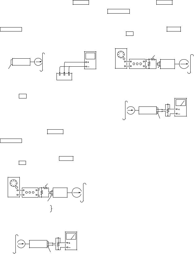
– Record Mode–
AF OSC
|
|
level meter |
attenuator |
10 k½ |
47 k½ |
|
|
+ |
|
|
set |
|
|
– |
|
600 ½ |
|
|
LINE IN |
LINE OUT |
Standard Input Level
Input terminal |
LINE IN |
|
|
source impedance |
10 kΩ |
|
|
input signal level |
0.5 V (–3.8 dB) |
|
|
Standard Output Level
Input terminal |
LINE IN |
|
|
source impedance |
10 kΩ |
|
|
input signal level |
0.5 V (–3.8 dB) |
|
|
Test Tape
Tape |
Contents |
Use |
|
|
|
P-4-A100 |
10 kHz, –10 dB |
Azimuth Adjustment |
|
|
|
WS-48B |
3 kHz, 0 dB |
Tape Speed Adjustment |
|
|
|
P-4-L300 |
315 Hz, 0 dB |
PB Level Adjustment |
|
|
|
0 dB = 0.775 V
Test Mode
1.While pressing the · (DECK A) and REC MUTING R buttons with the power off, press the U button to turn on the power. The fluorescent display tube lights up for about one sec-
ond, and the test mode is set. The test mode performs the following two special functions.
• Playback speed switching function
Pressing the HIGH/NORMAL button switches the playback speed between standard/double speed.
• Counter RESET & MEMORY function
Resets the counter when recording starts. When rewound with the 0(AMS) button after recording, stops at the point where recording started.
2. To release the test mode, turn OFF the power switch.
– 11 –
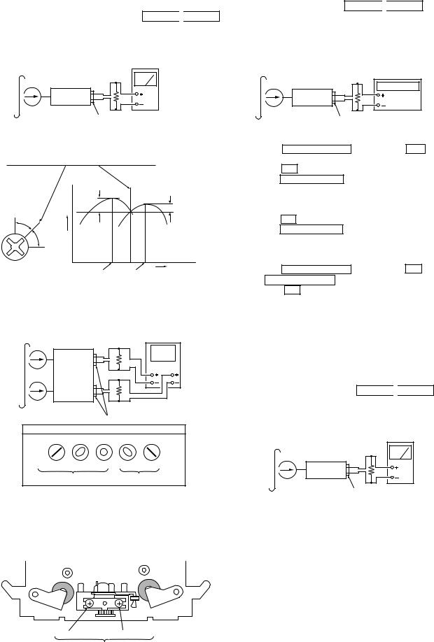
Record/Playback Head Azimuth Adjustment
DECK A 
 DECK B
Procedure:
1. Forward Playback Mode
test tape
P-4-A100 level meter (10 kHz, –10 dB)
47 k½
set
LINE OUT
2.Turn the adjustment screw for the maximum output levels. If these levels do not match, turn the adjustment screw until both of output levels match together within 1 dB.
L-CH |
output |
within |
|
|
within |
level |
1 dB |
|
|
||
peak |
|
|
|
1 dB |
|
|
|
|
|
||
R-CH |
|
|
|
|
|
peak |
|
|
|
|
screw position |
screw |
|
|
L-CH |
R-CH |
|
position |
|
|
|
||
|
|
|
peak |
peak |
|
3. Playback Mode |
|
|
|
|
|
test tape |
|
|
|
|
|
P-4-A100 |
|
|
|
|
|
(10 kHz, –10 dB) |
|
|
oscilloscope |
||
|
L-CH |
|
47 k½ |
|
|
|
set |
|
V |
H |
|
|
|
|
|
||
|
R-CH |
|
47 k½ |
|
|
|
|
|
LINE OUT |
|
|
|
|
Screen Pattern |
|
||
In phase |
45˚ |
90˚ |
135˚ 180˚ |
|
|
|
good |
|
wrong |
|
|
4.Change the reverse playback mode and repeat the steps 1 to 3.
5.After the adjustment, lock the adjustment screws with suitable locking compound.
Adjustment Location: – record/playback head –
reverse side |
forward side |
adjustment screws
Tape speed Adjustment DECK A 
 DECK B
Adjust DECK A first Procedure:
– Forward Playback Mode –
test tape |
|
WS-48B |
|
(3 kHz, 0 dB) |
frequency counter |
|
|
|
47 k½ |
|
set |
LINE OUT
(High speed adjustment)
1.Press the PITCH CONTROL button to set to OFF .
2.Set to test mode. (Refer to page 11.)
3.Press the · button to playback.
4.Press the HIGH/NORMAL button to playback at double speed.
5.Adjust RV316 (DECK A), RV416 (DECK B) so that the frequency counter reading becomes 5,980 ± 180 Hz.
(Normal speed adjustment)
6.Press the · button to playback.
7.Press the HIGH/NORMAL button to playback at normal speed.
8.Adjust RV317 (DECK A), RV417 (DECK B) so that the frequency counter reading becomes 3,000 ± 90 Hz.
(Pitch control adjustment) (DECK A)
9.Press the PITCH CONTROL button to set to ON .
10.Set PITCH CONTROL knob to mechanical center.
11.Press the · button to playback.
12.Adjust RV318 so that the frequency counter reading becomes 2,990 ± 90 Hz.
Adjustment Location: MAIN board (See page 14.)
Sample value of wow and flutter
W.RMS (JIS) less than 0.3% . (test tape : WS-48B)
Playback Level Adjustment DECK A 
 DECK B
Procedure:
– Forward Playback Mode –
test tape
P-4-L300 level meter (315 Hz, 0 dB)
47 k½
set
LINE OUT
Adjust DECK A : RV111 (L-CH), RV211 (R-CH) and
DECK B : RV121 (L-CH), RV221 (R-CH) so the level meter reading becomes the adjustment limits below.
Adjustment Value:
LINE OUT level : –7.7 ± 0.5 dB (0.301 to 0.338 V)
Level difference between channels : within 0.5 dB
Confirm that the LINE OUT level does not change in playback mode while changing the mode from playback to stop several times.
Adjustment Location: MAIN board (See page 14.)
– 12 –
Bias Consumption Current Adjustment DECK B
This adjustment should be performed when replacing the head assy or the bias oscillator transformer (T141, T241).
Setting:
REC LEVEL knob : standard recording position (See page 11.)
Procedure:
digital blank tape voltmeter CS-413
|
set |
|
|
|
LINE IN |
R-CH |
|
|
L-CH |
no signal |
|
|
|
TP441 |
|
1 |
2 |
3 |
|
|
|
1.Connect the digital voltmeter to test point TP441.
2.Set RV141 (L-CH), RV241 (R-CH) to mechanical center.
3.Press the · button to playback.
4.Adjust T141 (L-CH), T241 (R-CH) so that the digital voltmeter reading becomes minimum.
Adjustment Value: Maximum 220 mV
Adjustment Location: MAIN board (See page 14.)
Record Bias Adjustment DECK B
Setting:
REC LEVEL knob : standard record position (See page 11.)
Procedure:
1.Set to test mode (See page 11.)
2.Insert a tape into deck B, press the REC r button and then press the · button to start recording.
3.Record Mode
AF OSC |
|
10 k½ |
blank tape |
CS-123 |
attenuator |
|
|
|
|
|
set |
|
600 ½ |
|
|
|
LINE IN |
|
||
1) 315 |
Hz |
50 mV (–23.8 dB) |
|
2) 10 kHz |
|||
|
|||
4. Playback Mode
recorded |
level meter |
|
portion |
||
|
||
|
47 k½ |
|
|
set |
LINE OUT
5.Confirm playback the signal recorded in step 2 become adjustment level as follows.
If the selevels do not adjustment level, adjust the RV141 (L-CH) and RV241 (R-CH) to repeat steps 3 and 4.
Adjustment level:
The palyback output of 10 kHz level difference against 315 Hz reference should be ± 0.5 dB.
Adjustment Location: MAIN board (See page 14.)
Record Level Adjustment DECK B
Setting:
REC LEVEL knob : standard record position (See page 11.)
Procedure:
1.Set to test mode (See page 11.)
2.Insert a tspe into deck B, press the REC r button and then press the · button to start recording.
3.Record Mode
AF OSC
|
blank tape |
10 k½ |
CS-123 |
|
attenuator
set
600 ½  LINE IN
315 Hz, 50 mV (–23.8 dB)
4. Playback Mode
recorded |
level meter |
|
portion |
||
|
||
|
47 k½ |
|
|
set |
LINE OUT
5.Confirm playback the signal recorded in step 2 become adjustment level as follows.
If the selevels do not adjustment level, adjust the RV101 (L-CH) and RV201 (R-CH) to repeat steps 3 and 4.
Adjustment Value:
LINE OUT level : –23.8 ± 0.5 dB (47.2 to 53.0 mV)
Adjustment Location: MAIN board (See page 14.)
– 13 –
Loading...