


3-100-042-12 (1)
LCD Monitor
Operating Instructions
LMD-2050W
LMD-2450W
© 2007 Sony Corporation

WARNING
To reduce the risk of fire or electric shock, do not expose this apparatus to rain or moisture.
To avoid electrical shock, do not open the cabinet. Refer servicing to qualified personnel only.
WARNING
THIS APPARATUS MUST BE EARTHED.
For the customers in Europe
This product with the CE marking complies with both the EMC Directive and the Low Voltage Directive issued by the Commission of the European Community. Compliance with these directives implies conformity to the following European standards:
•EN60950-1: Product Safety
•EN55103-1: Electromagnetic Interference(Emission)
•EN55103-2: Electromagnetic Susceptibility(Immunity)
This product is intended for use in the following Electromagnetic Environments:
E1 (residential), E2 (commercial and light industrial),
E3 (urban outdoors), E4 (controlled EMCenvironment, ex. TV studio)
For the customers in Europe
The manufacturer of this product is Sony Corporation, 1-7-1 Konan, Minato-ku, Tokyo, Japan.
The Authorized Representative for EMC and product safety is Sony Deutschland GmbH, Hedelfinger Strasse 61, 70327 Stuttgart, Germany.
For any service or guarantee matters please refer to the addresses given in separate service or guarantee documents.
For the customers in the U.S.A.
This equipment has been tested and found to comply with the limits for a Class A digital device, pursuant to Part 15 of the FCC Rules. These limits are designed to provide reasonable protection against harmful interference when the equipment is operated in a commercial environment. This equipment generates, uses, and can radiate radio frequency energy and, if not installed and used in accordance with the instruction manual, may cause harmful interference to radio communications. Operation of this equipment in a residential area is likely to cause harmful interference in which case the user will be required to correct the interference at his own expense.
You are cautioned that any changes or modifications not expressly approved in this manual could void your authority to operate this equipment.
All interface cables used to connect peripherals must be shielded in order to comply with the limits for a digital device pursuant to Subpart B of Part 15 of FCC Rules.
WARNING:
Using this unit at a voltage other than 120 V may require the use of a different line cord or attachment plug, or both. To reduce the risk of fire or electric shock, refer servicing to qualified service personnel.
Attention-when the product is installed in Rack (LMD-2050W) :
1.Prevention against overloading of branch circuit
When this product is installed in a rack and is supplied power from an outlet on the rack, please make sure that the rack does not overload the supply circuit.
2.Providing protective earth
When this product is installed in a rack and is supplied power from an outlet on the rack, please confirm that the outlet is provided with a suitable protective earth connection.
3.Internal air ambient temperature of the rack
When this product is installed in a rack, please make sure that the internal air ambient temperature of the rack is within the specified limit of this product.
4.Prevention against achieving hazardous condition due to uneven mechanical loading
When this product is installed in a rack, please make sure that the rack does not achieve hazardous condition due to uneven mechanical loading.
5.Install the equipment while taking the operating temperature of the equipment into consideration
For the operating temperature of the equipment, refer to the specifications of the Operation Manual.
6.When performing the installation, keep the following space away from walls in order to obtain proper exhaust and radiation of heat.
Lower, Upper : 4.4 cm (1 3/4 inches) or more
WARNING
When installing the unit, incorporate a readily accessible disconnect device in the fixed wiring, or connect the power cord to an easily accessible socketoutlet near the unit. If a fault should occur during operation of the unit, operate the disconnect device to switch the power supply off, or disconnect the power cord.
2

For the customers in the USA
Lamp in this product contains mercury. Disposal of these materials may be regulated due to environmental considerations. For disposal or recycling information, please contact your local authorities or the Electronic Industries Alliance (www.eiae.org).
3

Table of Contents |
|
Precaution .............................................................. |
5 |
On Safety ............................................................ |
5 |
On Installation .................................................... |
5 |
Handling the LCD Screen .................................. |
5 |
About the Fluorescent Tube ............................... |
5 |
On Cleaning ....................................................... |
5 |
On Repacking ..................................................... |
6 |
On Mounting on a Rack ..................................... |
6 |
On Fan Error (LMD-2450W) ............................. |
6 |
Features .................................................................. |
6 |
Location and Function of Parts and Controls .... |
8 |
Front Panel ......................................................... |
8 |
Input signals and adjustable/setting items ........ |
10 |
Rear/Bottom Panel ........................................... |
11 |
Installing to the Rack (LMD-2050W only) ....... |
13 |
Adjusting the Height of the Stand ..................... |
14 |
Connecting the AC Power Cord ......................... |
15 |
Installing the Input Adaptor .............................. |
16 |
Selecting the Default Settings ............................. |
16 |
Selecting the Menu Language ............................ |
18 |
Using the Menu .................................................... |
19 |
Adjustment Using the Menus ............................. |
20 |
Items ................................................................. |
20 |
Adjusting and Changing the Settings ............... |
21 |
STATUS menu............................................. |
21 |
COLOR TEMP/SPACE menu..................... |
22 |
USER CONTROL menu.............................. |
22 |
USER CONFIG menu.................................. |
25 |
REMOTE menu ........................................... |
29 |
KEY INHIBIT menu.................................... |
30 |
Troubleshooting ................................................... |
31 |
Specifications ....................................................... |
32 |
Dimensions ........................................................... |
37 |
4 Table of Contents

Precaution
On Safety
•Operate the unit only with a power source as specified in the “Specifications” section.
•A nameplate indicating operating voltage, etc., is located on the rear panel.
•Should any solid object or liquid fall into the cabinet, unplug the unit and have it checked by qualified personnel before operating it any further.
•Do not drop or place heavy objects on the power cord. If the power cord is damaged, turn off the power immediately. It is dangerous to use the unit with a damaged power cord.
•Unplug the unit from the wall outlet if it is not to be used for several days or more.
•Disconnect the power cord from the AC outlet by grasping the plug, not by pulling the cord.
•The socket-outlet shall be installed near the equipment and shall be easily accessible.
On Installation
•Allow adequate air circulation to prevent internal heat build-up.
Do not place the unit on surfaces (rugs, blankets, etc.) or near materials (curtains, draperies) that may block the ventilation holes.
•Do not install the unit in a location near heat sources such as radiators or air ducts, or in a place subject to direct sunlight, excessive dust, mechanical vibration or shock.
Handling the LCD Screen
•The LCD panel fitted to this unit is manufactured with high precision technology, giving a functioning pixel ratio of at least 99.99%. Thus a very small proportion of pixels may be “stuck”, either always off (black), always on (red, green, or blue), or flashing. In addition, over a long period of use, because of the physical characteristics of the liquid crystal display, such “stuck” pixels may appear spontaneously. These problems are not a malfunction.
•Do not leave the LCD screen facing the sun as it can damage the LCD screen. Take care when you place the unit by a window.
•Do not push or scratch the LCD monitor’s screen. Do not place a heavy object on the LCD monitor’s screen. This may cause the screen to lose uniformity.
•If the unit is used in a cold place, horizontal lines or a residual image may appear on the screen. This is not a malfunction. When the monitor becomes warm, the screen returns to normal.
•If a still picture is displayed for a long time, a residual image may appear. The residual image will eventually disappear.
•The screen and the cabinet become warm during operation. This is not a malfunction.
About the Fluorescent Tube
A specially designed fluorescent tube is installed as the lighting apparatus for this unit. If the LCD screen becomes dark, unstable or does not turn on, consult your Sony dealer.
On Cleaning
Before cleaning
Be sure to disconnect the AC power cord from the AC outlet.
On cleaning the monitor screen
The monitor screen surface is especially treated to reduce reflection of light.
As incorrect maintenance may impair the performance of the monitor, take care with respect to the following:
•Wipe the screen gently with a soft cloth such as a cleaning cloth or glass cleaning cloth.
•Stubborn stains may be removed with a soft cloth such as a cleaning cloth or glass cleaning cloth lightly dampened with water.
•Never use solvent such as alcohol, benzene or thinner, or acid, alkaline or abrasive detergent, or chemical cleaning cloth, as they will damage the screen surface.
On cleaning the cabinet
•Clean the cabinet gently with a soft dry cloth. Stubborn stains may be removed with a cloth lightly dampened with mild detergent solution, followed by wiping with a soft dry cloth.
•Use of alcohol, benzene, thinner or insecticide may damage the finish of the cabinet or remove the indications on the cabinet. Do not use these chemicals.
•If you rub on the cabinet with a stained cloth, the cabinet may be scratched.
•If the cabinet is in contact with a rubber or vinyl resin product for a long period of time, the finish of the cabinet may deteriorate or the coating may come off.
Precaution 5
On Repacking
Do not throw away the carton and packing materials. They make an ideal container which to transport the unit.
On Mounting on a Rack
Leave 1U space empty above and below the monitor to ensure adequate air circulation or install a fan to maintain the monitor’s performance.
If you have any questions about this unit, contact your authorized Sony dealer.
On Fan Error (LMD-2450W)
The fan for cooling the unit is built in. When the fan stops and the RETURN button on the front panel blinks for fan error indication, turn off the power and contact an authorized Sony dealer.
About this manual
The instructions in this manual are for the following two models:
•LMD-2050W
•LMD-2450W
The illustration of LMD-2050W is used for the explanations.
Any differences in specifications are clearly indicated in the text.
Features
The LMD-2450W (24-inch)/LMD-2050W (20-inch) is a multiple format LCD monitor for broadcast or business use featuring a precise image and high performance. It supports both digital or analog main broadcast signal and PC input. It is also equipped with functions to adjust for various objects or use.
High brightness LCD panel
Because of precise image, wide viewing angle technology and high speed response, real color image can be reproduced.
Multi-format
The monitor supports the video, Y/C, RGB, component, SDI (HD/D1, when the optional input adaptor is used.) signals and NTSC/PAL color systems. HD15 (analog) and DVI-D (digital) connectors are equipped for the PC input.
For more information, refer to “Available signal formats” on page 34.
Expandable input capability
The input connector configuration can be easily modified by installing the optional input adaptor into the optional input slot on the bottom of the monitor. Up to two adaptors can be installed.
For more information, refer to “Available signal formats” on page 34.
External remote function
The input signal is selected or various items are adjusted by use of the serial (Ethernet) remote function. Up to 32 monitors and control units (max. 4) can be connected by the Ethernet (10BASE-T/100BASE-TX) connection and controlled remotely on the network. You can control individual monitors or monitor groups simply by entering the monitor ID or group ID number. You can also execute the same operation on all connected monitors, or put all connected monitors into the same setup and adjustment state.
For more information, refer to SERIAL REMOTE of “REMOTE menu” on page 29.
Refer to the Operation Manual of the BKM-15R Monitor Control Unit.
Monitor stand with tilt function
A monitor stand with tilt function is equipped. You can select the height of the monitor by adjusting the height, when it is used on a desk.
For more information, refer to “Adjusting the Height of the Stand” on page 14.
6 Features

Rack mount
The monitor supports the VESA (100 × 100) standard. The LMD-2050W may be mounted on an EIA-standard 19-inch rack (using an optional mounting bracket).
Two-display
Two kinds of input signals are put on the monitor.
For more information, refer to MULTI DISPLAY of “MULTI DISPLAY SETTING” on page 27.
Input signal waveform and audio level display
The waveform of the input signal or the audio level (embedded audio only) is displayed as the sub display.
For more information, refer to SUB INPUT SELECT and WAVE FORM of “MULTI DISPLAY SETTING” on page 27.
Closed caption
The closed caption conforming to the EIA608 standard is displayed.
Auto chroma/phase function
The chroma and phase of the decoder are automatically adjusted with the auto chroma/phase function.
Blue only mode
In the blue only mode, a monochrome display is obtained with all three of the R/G/B picture elements driven with a blue signal. This mode is convenient for chroma and phase adjustments and monitoring of VCR noise.
H/V delay mode
The horizontal and vertical sync signals can be monitored simultaneously.
Selectable marker/scan display
Various items for broadcast use can be displayed. The center marker, safe area marker, aspect marker or display size (scan), etc are displayed by selecting according to use.
For more information, refer to “MARKER SETTING” on page 26 and SCAN of “SYSTEM SETTING” on page 25.
APA (Auto Pixel Alignment) function
For the signal input to the HD15 input connector, you can adjust the picture to the appropriate size simply by pressing the button assigned as the APA function.
Select color temperature mode
You can select the color temperature from among two (9300 K, 6500 K) settings.
Color space feature
You can select one from among three color space settings (SMPTE-C/EBU/ITU-R BT.709).
On-screen menus
You can set the appropriate settings according to the connected system by using the on-screen menus.
Select language display
You can select from seven display languages, English, French, German, Spanish, Italian, Japanese and Chinese.
Key inhibit function
You can inhibit a key function to prevent missing an operation.
Features 7
Location and Function of Parts and Controls
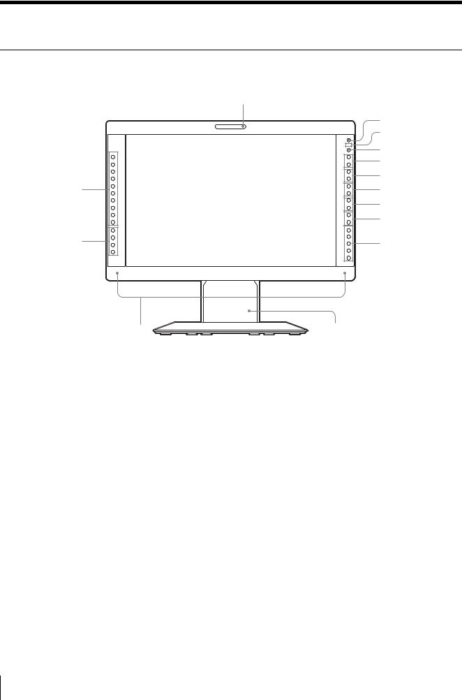
Front Panel
1
|
COMPOSITE |
+ |
|
|
|
|
Y/C |
– |
|
RGB |
+ |
|
COMPONENT |
|
|
|
– |
qa |
A-2 |
+ |
– |
||
|
A-1 |
|
|
B-1 |
+ |
|
B-2 |
– |
|
HD15 |
+ |
|
DVI |
– |
|
F1 |
|
qs |
F2 |
+ |
F3 |
– |
|
|
F4 |
|
2
3
4
5
6
7
8
9
0
qd |
qf |
a Tally lamp
You can check the status of the monitor by the color of the tally lamp.
The tally lamp lights in red, green or amber according to the setting of PARALLEL REMOTE in the REMOTE menu.
b 1 (standby) switch and indicator
When you press the switch to turn on the power in standby mode (the a/? switch on the rear panel is turned on), the indicator lights in green.
When you press this switch again, the monitor is set in standby mode and the indicator lights in red.
c -(key inhibit) indicator
Lights in red when the key inhibit is set to ON.
d CONTROL button
Press to display the buttons on the front panel. Press again to clear the display.
e VOLUME buttons
Press the + button to increase the volume or the – button to decrease it.
f CONTRAST buttons
Adjusts the picture contrast.
Press the + button to make the contrast higher or the – button to make it lower.
g PHASE buttons
Adjusts color tones.
Press the + button to make the skin tones greenish or the
– button to make them purplish.
h CHROMA buttons
Adjusts the color intensity.
Press the + button to increase the color intensity or the – button to decrease it.
i BRIGHT (brightness) buttons
Adjusts the picture brightness.
Press the + button to increase the brightness or the – button to decrease it.
j Menu operation buttons
Displays or sets the on-screen menu.
MENU button
Press to display the on-screen menu. Press again to clear the menu.
8 Location and Function of Parts and Controls
+/– buttons
Press to select the items and setting values.
ENTER button
Press to confirm a selected item on the menu. When the menu is not displayed and the button is
pressed, the distinguished signal format is displayed.
RETURN button
When the menu is displayed and the button is pressed, the value of an item is reset to the previous value. When the menu is not displayed and the button is pressed, the function selected in FUNCTION BUTTON SETTING of the USER CONFIG menu is displayed on the side of the F1 to F4 button. Also, when the fan stops, this button blinks.
k Input select buttons
Press the button to monitor the signal input to each connector.
A-1, A-2, B-1 and B-2 buttons are used when an optional input adaptor has been installed in the option slot.
COMPOSITE button: to monitor the signal through the COMPOSITE IN connector
Y/C button: to monitor the signal through the Y/C IN connector
RGB button: to monitor the RGB signal through the connectors for the R/G/B signal input COMPONENT button: to monitor the component signal through the connectors for Y/PB/PR signal input A-1 button: to monitor the signal from connector 1 (the connectors for the R/G/B signal input in BKM229X) of the input adaptor installed to the option slot A
A-2 button: to monitor the signal from connector 2 (the connectors for Y/PB/PR signal input in BKM229X) of the input adaptor installed to the option slot A
B-1 button: to monitor the signal from connector 1 (the connectors for the R/G/B signal input in BKM229X) of the input adaptor installed to the option slot B
B-2 button: to monitor the signal from connector 2 (the connectors for Y/PB/PR signal input in BKM229X) of the input adaptor installed to the option slot B
HD15 button: to monitor the signal through the HD15 input connector
DVI button: to monitor the signal through the DVI-D input connector
l Function buttons
You can turn the assigned function on or off. The factory setting is as follows;
F1 button: EXT SYNC
F2 button: SCAN
F3 button: ASPECT
F4 button: H/V DELAY
You can assign the function from among SCAN, ASPECT, EXT SYNC, BLUE ONLY, MONO, MARKER, H/V DELAY, MULTI DISPLAY, CLOSED CAPTION and APA in FUNCTION BUTTON SETTING of the USER CONFIG menu (see page 28).
For details of the function assigned to the function button, see page 28.
m Speakers
The audio signal which is selected by the input select button is output.
When BKM-220D or BKM-243HS is not installed, the audio signal which is selected in INPUT SELECT of the USER CONFIG menu is output (see page 29).
When BKM-220D or BKM-243HS is installed, the audio signal of the channel which is selected in OPTION AUDIO SETTING of the USER CONFIG menu is output (see page 29).
The audio signals from the speakers are output from the AUDIO L/R OUT connector on the rear (see page 12).
n Stand
You can adjust the height of the monitor (see page 14).
Location and Function of Parts and Controls |
9 |
|
|

Input signals and adjustable/setting items
|
|
|
|
|
|
Input signal |
|
|
|
|
||
|
|
|
|
|
|
|
|
|
|
|
|
|
Item |
Video*3, |
B & W*3 |
Component*4 |
RGB*4 |
SDI |
Computer |
||||||
|
|
Y/C*3 |
|
|
|
|
|
|
|
|
|
|
|
|
|
SD |
HD |
SD |
HD |
D1*5 |
HD*6 |
DVI |
HD15 |
||
CONTRAST*1 |
a |
a |
a |
a |
a |
a |
a |
a |
a |
a |
||
|
|
|
|
|
|
|
|
|
|
|
||
BRIGHT*1 |
a |
a |
a |
a |
a |
a |
a |
a |
a |
a |
||
|
|
|
|
|
|
|
|
|
|
|
||
CHROMA*1 |
a |
× |
a |
a |
× |
× |
a |
a |
a |
a |
||
|
|
|
|
|
|
|
|
|
|
|
||
PHASE*1 |
a |
× |
× |
× |
× |
× |
× |
× |
a |
a |
||
|
|
(NTSC) |
|
|
|
|
|
|
|
|
|
|
|
|
|
|
|
|
|
|
|
|
|
||
APERTURE |
a |
a |
a |
a |
a |
a |
a |
a |
a |
a |
||
|
|
|
|
|
|
|
|
|
|
|
||
COLOR TEMP |
a |
a |
a |
a |
a |
a |
a |
a |
a |
a |
||
|
|
|
|
|
|
|
|
|
|
|
||
COLOR SPACE |
a |
a |
a |
a |
a |
a |
a |
a |
a |
a |
||
|
|
|
|
|
|
|
|
|
|
|
||
AUTO CHROMA/ |
a |
× |
a |
a |
× |
× |
× |
× |
× |
× |
||
PHASE |
||||||||||||
|
|
|
|
|
|
|
|
|
|
|||
|
|
|
|
|
|
|
|
|
|
|
||
ACC |
a |
× |
× |
× |
× |
× |
× |
× |
× |
× |
||
|
|
|
|
|
|
|
|
|
|
|
||
CTI |
a |
× |
a |
× |
× |
× |
× |
× |
× |
× |
||
|
|
|
|
|
|
|
|
|
|
|
||
V SHARPNESS |
a |
a |
a |
× |
a |
× |
a |
× |
× |
× |
||
|
|
|
|
|
|
|
|
|
|
|
||
MATRIX*2 |
× |
× |
a |
× |
× |
× |
× |
× |
× |
× |
||
|
|
|
|
|
|
|
|
|
|
|
||
COMPONENT LEVEL |
× |
× |
a |
× |
× |
× |
× |
× |
× |
× |
||
|
|
|
|
(480/60I) |
|
|
|
|
|
|
|
|
NTSC SETUP |
a |
a |
× |
× |
× |
× |
× |
× |
× |
× |
||
|
|
(NTSC) |
(480/60I) |
|
|
|
|
|
|
|
|
|
|
|
|
|
|
|
|
|
|
|
|
||
SCAN |
a |
a |
a |
a |
a |
a |
a |
a |
× |
× |
||
|
|
|
|
|
|
|
|
|
|
|
||
ASPECT |
a |
a |
a |
× |
a |
× |
a |
× |
× |
× |
||
|
|
|
|
|
|
|
|
|
|
|
||
MARKER |
a |
a |
a |
a |
a |
a |
a |
a |
× |
× |
||
|
|
|
|
|
|
|
|
|
|
|
||
BLUE ONLY |
a |
× |
a |
a |
a |
a |
a |
a |
× |
× |
||
|
|
|
|
|
|
|
|
|
|
|
||
MONO |
a |
× |
a |
a |
× |
× |
a |
a |
× |
× |
||
|
|
|
|
|
|
|
|
|
|
|
||
H/V DELAY |
a |
a |
a |
a |
a |
a |
a |
a |
× |
× |
||
|
|
|
|
|
|
|
|
|
|
|
||
APA |
× |
× |
× |
× |
× |
× |
× |
× |
× |
a |
||
|
|
|
|
|
|
|
|
|
|
|
||
SIZE |
× |
× |
× |
× |
× |
× |
× |
× |
× |
a |
||
|
|
|
|
|
|
|
|
|
|
|
||
SHIFT |
a |
a |
a |
a |
a |
a |
a |
a |
× |
a |
||
|
|
|
|
|
|
|
|
|
|
|
||
PITCH |
× |
× |
× |
× |
× |
× |
× |
× |
× |
a |
||
|
|
|
|
|
|
|
|
|
|
|
||
DOT PHASE |
× |
× |
× |
× |
× |
× |
× |
× |
× |
a |
||
|
|
|
|
|
|
|
|
|
|
|
||
POWER SAVING |
a |
a |
a |
a |
a |
a |
a |
a |
a |
a |
||
|
|
|
|
|
|
|
|
|
|
|
||
PICTURE DELAY |
a |
a |
a |
a |
a |
a |
a |
a |
× |
× |
||
MIN*7 |
|
|
|
|
|
|
|
|
|
|
||
MULTI DISPLAY |
a |
a |
a |
a |
a |
a |
a |
a |
a |
a |
||
|
|
|
|
|
|
|
|
|
|
|
||
CLOSED CAPTION |
a*8 |
a*8 |
× |
× |
× |
× |
× |
× |
× |
× |
||
a : Adjustable/can be set
× : Not adjustable/cannot be set
*1 Adjustment of SUB CONTROL is the same.
*2 When a component signal (480/60I or 480/60P) is input and the COMPONENT LEVEL is set to SMPTE, this can be switchable.
*3 When a BKM-227W is installed, the number of the
input connector is increased.
*4 When a BKM-229X is installed, the number of the input connector is increased.
*5 When a BKM-220D or BKM-243HS is installed, the signal is input.
*6 When a BKM-243HS is installed, the signal is input. *7 Only the interlace signal is input.
*8 Only an NTSC signal is input.
10 Location and Function of Parts and Controls

Rear/Bottom Panel
1 2 3
4 5 6 7 8 9 0
–
qa qs
qd
qf qg qh |
qj |
qk |
a a/? (power) switch
The power is turned on or off.
The monitor is turned on by pressing side ?.
b AC IN socket
Connect the supplied AC power cord.
c DC 24V IN connector
Plug the DC 24V power supply to this connector to provide power to the monitor.
d AUDIO L/R IN connectors (phono jack)
Connect to the audio outputs of a VCR or to an audio mixer.
e COMPOSITE IN connector (BNC)
Input connector for composite signals.
f Y/C IN connector (4-pin mini-DIN)
Input connector for Y/C signals.
g G/Y IN connector (BNC)
Input connector for G of RGB signals and component Y (luminance) signals.
h B/PB IN connector (BNC)
Input connector for B of RGB signals and PB (blue color difference) of component signals.
i R/PR IN connector (BNC)
Input connector for R of RGB signals and PR (red color difference) of component signals.
jEXT SYNC IN/OUT (external sync) connectors (BNC)
To use the external sync signal, press the function button that EXT SYNC is assigned (F1 button at the factory setting).
IN connector
When this unit operates on an external sync signal, connect the reference signal from a sync generator to this connector.
Note
When inputting a video signal with the jitters, etc. the picture may be disturbed. We recommend using the TBC (time base corrector).
OUT connector
Loop-through output of the IN connector. Connect to the external sync input of video equipment to be synchronized with this unit.
When the cable is connected to this connector, the 75-ohm termination of the input is automatically released, and the signal input to the IN connector is output from this connector.
Location and Function of Parts and Controls |
11 |
|
|

k AUDIO L/R OUT connectors (phono jack)
Outputs the audio signal which is selected by the input select button on the front panel.
When BKM-220D or BKM-243HS is not installed, output the audio signal which is selected in INPUT SELECT of the USER CONFIG menu (see page 29). When BKM-220D or BKM-243HS is installed, output the audio signal of the channel which is selected in OPTION AUDIO SETTING of the USER CONFIG menu (see page 29).
The audio signal from this connector is monitored on the front speakers (see page 9).
l Loop-through output connectors
Outputs the signals input to the input connectors (5 to 9). Connect to the analog input (composite, Y/C, analog component or analog RGB) of equipment, according to the input signal.
m Optional input slot
An optional input adaptor can be installed according to your system configuration (see page 16).
The left side slot is A and the right side slot B. Press the A-1, A-2, B-1 or B-2 button to select the signal.
nPARALLEL REMOTE connector (modular connector, 8-pin)
Forms a parallel switch and controls the monitor externally.
For details on the pin assignment and factory setting function assigned to each pin, see page 33.
CAUTION
For safety, do not connect the connector for peripheral device wiring that might have excessive voltage to this port. Follow the instructions for this port.
o SERIAL REMOTE connector (RJ-45)
Connect to the network or Sony BKM-15R Monitor Control Unit by using a 10BASE-T/100BASE-TX LAN cable (shielded type, optional).
For details, refer to the Interface Manual for Programmers (saved in the supplied CD-ROM, Japanese and English only.)
CAUTION
•When an optional LAN cable is connected, use a shield type cable to prevent miss-operation due to noises.
•For safety, do not connect the connector for peripheral device wiring that might have excessive voltage to this port. Follow the instructions for this port.
•The connection speed may be affected by the network system. This unit does not guarantee the communication speed or quality of 10BASE-T/ 100BASE-TX.
p SERIAL REMOTE RS-232C connector (D-sub
9-pin, female)
Connect to the RS-232C control connector on external equipment connected to the monitor. The monitor can be operated according to control commands sent from external equipment connected to it.
For details on the pin assignment and factory setting function assigned to each pin, see page 33.
For details, refer to the Interface Manual for Programmers (saved in the supplied CD-ROM, Japanese and English only.)
q DVI-D input connector (DVI-D)
Inputs DVI Rev.1.0 applicable digital RGB signal.
To view the signals of the SXGA and higher resolution when the DVI input is selected, use the cable within 3 m (118 1/8 inches) in length.
r HD15 input connector (D-sub 15 pin, female)
Inputs an analog RGB video signal (0.7 Vp-p, positive polarity) and sync signal.
The Plug & Play function corresponds to DDC2B.
12 Location and Function of Parts and Controls
 Loading...