


 Loading...
LCD MONITOR
LMD-2450W LMD-2450MC LMD-2450MD
LMD-2050W
SERVICE MANUAL 1st Edition (Revised 2)

! WARNING
This manual is intended for qualified service personnel only.
To reduce the risk of electric shock, fire or injury, do not perform any servicing other than that contained in the operating instructions unless you are qualified to do so. Refer all servicing to qualified service personnel.
! WARNUNG
Die Anleitung ist nur für qualifiziertes Fachpersonal bestimmt.
Alle Wartungsarbeiten dürfen nur von qualifiziertem Fachpersonal ausgeführt werden. Um die Gefahr eines elektrischen Schlages, Feuergefahr und Verletzungen zu vermeiden, sind bei Wartungsarbeiten strikt die Angaben in der Anleitung zu befolgen. Andere als die angegeben Wartungsarbeiten dürfen nur von Personen ausgeführt werden, die eine spezielle Befähigung dazu besitzen.
! AVERTISSEMENT
Ce manual est destiné uniquement aux personnes compétentes en charge de l’entretien. Afin de réduire les risques de décharge électrique, d’incendie ou de blessure n’effectuer que les réparations indiquées dans le mode d’emploi à moins d’être qualifié pour en effectuer d’autres. Pour toute réparation faire appel à une personne compétente uniquement.
WARNING
This unit has no power switch.
When installing the unit, incorporate a readily accessible disconnect device in the fixed wiring, or connect the power cord to a socket-outlet which must be provided near the unit and easily accessible, so that the user can turn off the power in case a fault should occur.
WARNUNG
Dieses Gerät hat keinen Netzschalter.
Beim Einbau des Geräts ist daher im Festkabel ein leicht zugänglicher Unterbrecher einzufügen, oder das Netzkabel muß mit einer in der Nähe des Geräts befindlichen, leicht zugänglichen Wandsteckdose verbunden werden, damit sich bei einer Funktionsstörung die Stromversorgung zum Gerät jederzeit unterbrechen läß t.
LMD-2450W
Table of Contents
Manual Structure
Purpose of this manual ................................................................. |
3 |
Related manuals ........................................................................... |
3 |
1. |
Service Overview |
|
|
1-1. |
Appearance Figure .......................................................... |
1-1 |
|
1-2. |
Board Location ............................................................... |
1-1 |
|
1-3. |
Disassembly .................................................................... |
1-2 |
|
1-3-1. |
Rear Cover ............................................................. |
1-2 |
|
1-3-2. |
Q Board ................................................................. |
1-3 |
|
1-3-3. |
Connector Plate Assembly/T Board ...................... |
1-4 |
|
1-3-4. |
G1 Board (LMD-2050W/2450W)/G2 Board ........ |
1-5 |
|
1-3-5. |
B Board ................................................................. |
1-6 |
|
1-3-6. |
Inverter Board (LMD-2050W) .............................. |
1-7 |
|
1-3-7. |
HB1 Board/HB2 Board/X Board |
|
|
|
|
(LMD-2050W) ...................................................... |
1-8 |
1-3-8. |
HA1 Board/HA2 Board/X Board |
|
|
|
|
(LMD-2450W/2450MD/2450MC) ....................... |
1-9 |
1-3-9. |
G3 Board/S Board |
|
|
|
|
(LMD-2450W/2450MD/2450MC) ..................... |
1-11 |
1-3-10. |
DC Fan (LMD-2450W/2450MD/2450MC) ........ |
1-12 |
|
1-3-11. |
Speaker (LMD-2050W/2450W) ......................... |
1-13 |
|
1-3-12. |
LCD Panel ........................................................... |
1-14 |
|
1-3-13. |
G1 Board (LMD-2450MD/2450MC) .................. |
1-15 |
|
1-4. |
Unleaded Solder ............................................................ |
1-16 |
|
1-5. |
Warning on Power Connection ..................................... |
1-16 |
|
2. |
Electrical Alignments |
|
2-1. |
Preparation ...................................................................... |
2-1 |
2-2. |
White Balance Adjustment ............................................. |
2-1 |
2-3. |
A/D Adjustment (COMPONENT) ................................. |
2-2 |
2-4. |
A/D Adjustment (RGB) .................................................. |
2-2 |
2-5. |
A/D Adjustment (COMPOSITE) ................................... |
2-3 |
2-6. |
A/D Adjustment (Y/C) ................................................... |
2-3 |
2-7. |
A/D Adjustment (COMPUTER) .................................... |
2-4 |
3. |
Troubleshooting |
|
3-1. |
Backlight does not light .................................................. |
3-1 |
3-2. |
System does not start ...................................................... |
3-2 |
3-3. |
Control operation of this unit is abnormal ...................... |
3-2 |
3-4. |
Image is abnormal ........................................................... |
3-3 |
3-5. |
TALLY lamp is not lit .................................................... |
3-3 |
3-6. |
Fan is abnormal (LMD-2450W/2450MD/2450MC) ...... |
3-4 |
4. |
Spare Parts |
|
4-1. |
Notes on Repair Parts ..................................................... |
4-1 |
4-2. |
Exploded Views .............................................................. |
4-2 |
4-3. |
Packing Materials & Supplied Accessories .................. |
4-18 |
5.Block Diagrams
6.Frame Wiring
LMD-2450W |
1 |

Manual Structure
Purpose of this manual
This manual is the Service Manual of the LCD Monitor LMD-2450W/2450MC/ 2450MD/2050W.
This manual contains the service overview, electrical alignments, troubleshooting, spare parts, block diagrams, and frame wiring.
The service of this unit is basically performed by the replacement of board. Therefore, the schematic diagram, board layout and electrical parts list are not contained.
Related manuals
In addition to this Service Manual the following manual is provided.
.“Instruction Manual” PRINT/CD-ROM (Supplied with this unit)
Part No.: 3-100-040-XX (LMD-2450W/2050W) PRINT 3-100-041-0X (LMD-2450W/2050W) CD-ROM 3-113-888-1X (LMD-2450MC) PRINT 3-113-888-XX (LMD-2450MD) PRINT 3-113-889-0X (LMD-2450MD) CD-ROM
This manual describes the information (basic function and use of this unit) required for the operation of this unit.
.“Semiconductor Pin Assignments” CD-ROM (Available on request)
This “Semiconductor Pin Assignments” CD-ROM allows you to search for semiconductors used in Broadcast and Professional equipment.
Part number: 9-968-546-06
LMD-2450W |
3 |
Section 1
Service Overview
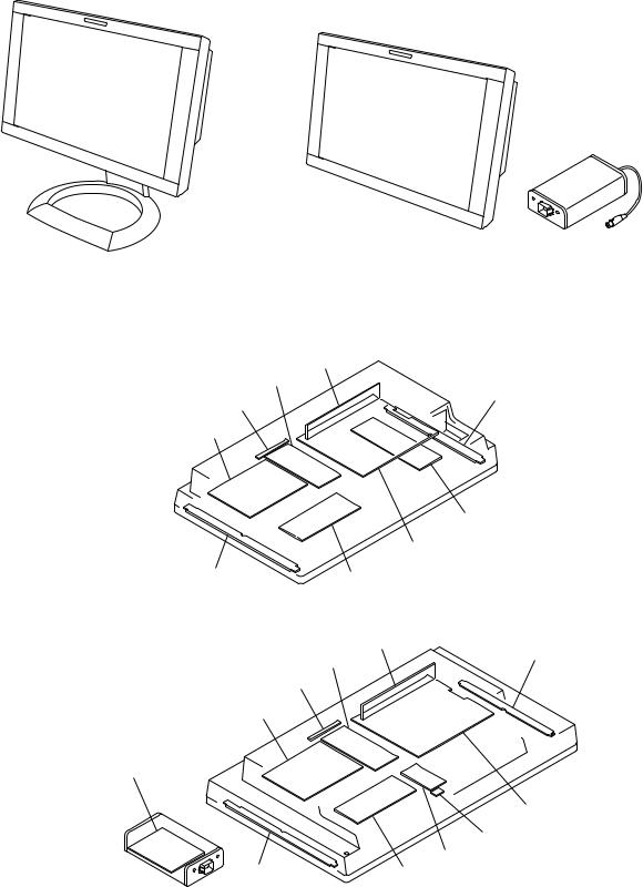
1-1. Appearance Figure
LMD-2050W/LMD-2450W |
LMD-2450MD/2450MC |
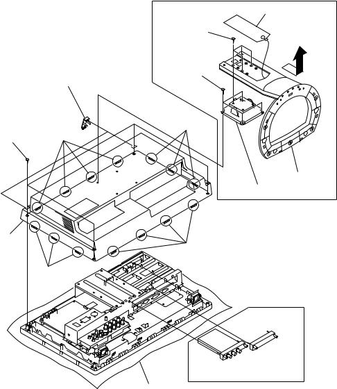
1-2. Board Location
LMD-2050W
T board
G2 board
HB2 board
X board
G1 board
Inverter board
B board
HB1 board |
Q board |
LMD-2450W/2450MD/2450MC
T board
HA2 board
G2 board
X board
G1 board (LMD-2450W)
G1 board (LMD-2450MD/2450MC)
B board
S board
|
G3 board |
HA1 board |
Q board |
LMD-2450W |
1-1 |
1-3. Disassembly
m
. In this section, remove parts in the order of numbers shown in the figure.
. When removing/installing the cabinet and replacing the board, place the unit on the conductive cushion.
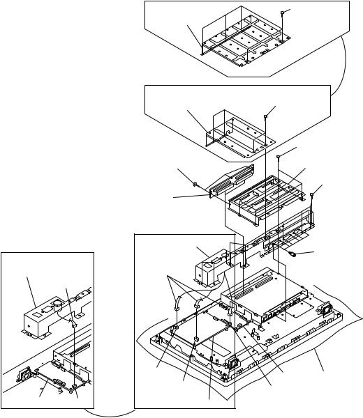
1-3-1. Rear Cover
|
LMD-2050W/2450W |
|
1 Top arm cover |
|
2 Four screws |
|
(B4 x12) |
|
4 Four screws |
|
(B4 x12) |
6 Screw covers |
|
7 Four screws |
!- Three hooks |
|
|
(BVTP 4 x8) 8 Four hooks |
|
|
3 Stand |
|
5 Hinge assembly |
!= Rear cover
!/ Four hooks
9 Three hooks
LMD-2450MD/2450MC
Cushion
1-2 |
LMD-2450W |

1-3-2. Q Board
. Remove the rear cover. (Refer to Section 1-3-1.)
The illustration indicates LMD-2050W.
3 Two harnesses
1 Four screws (PWH3 x6)
2 Q board
J10
J14
Cushion
LMD-2450W |
1-3 |
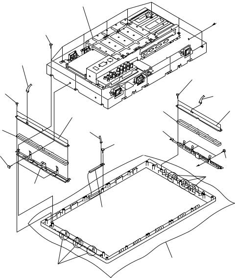
1-3-3. Connector Plate Assembly/T Board
. Remove the rear cover. (Refer to Section 1-3-1.)
. Remove the Q board. (Refer to Section 1-3-2.)
LMD-2450W/2450MD/2450MC
2 Wall mount bracket
LMD-2050W
2 Wall mount bracket
9 Three screws
|
(PWH3 x6) |
|
|
!/ T board |
|
|
LMD-2050W/2450W |
|
LMD-2450MD/2450MC |
6 Connector plate |
|
assembly |
||
|
||
6 Connector plate |
3 Three |
|
assembly |
harnesses |
|
3 Harness |
|
CN602
CN601
G2 board CN751 |
G1 board |
1 Five screws (PWH3 x6)
1Four screws (PWH3 x6)
7Four screws (PWH3 x6)
8 Option case
5 Nine screws (PWH3 x6)
4 Six connector screws
G2 board Cushion
CN752
1-4 |
LMD-2450W |
1-3-4. G1 Board (LMD-2050W/2450W)/G2 Board
.Refer to Section 1-3-13 for how to remove the G1 board of LMD-2450MD/2450MC. The G2 board is removed in common.
. Remove the rear cover. (Refer to Section 1-3-1.)
. Remove the Q board. (Refer to Section 1-3-2.)
. Remove the connector plate assembly and option case. (Refer to Section 1-3-3.)
6 Four screws |
2 Three harnesses |
(PWH3 x6) |
|
3 Four screws |
|
(PWH3 x6) |
|
1 Harness |
|
5 G1 board |
8 G2 board |
|
4 Board holder
7 Board holder |
Cushion |
LMD-2450W |
1-5 |

1-3-5. B Board
. Remove the rear cover. (Refer to Section 1-3-1.)
. Remove the Q board. (Refer to Section 1-3-2.)
. Remove the connector plate assembly and option case. (Refer to Section 1-3-3.)
The illustration indicates LMD-2050W.
1Six screws (PWH3 x6)
2 Main case
4 Five harnesses |
LVDS cable |
5 Two harnesses
6 Five screws (PWH3 x6)
7 B board
3 Two harnesses
Cushion
1-6 |
LMD-2450W |

1-3-6. Inverter Board (LMD-2050W)
. Remove the rear cover. (Refer to Section 1-3-1.)
. Remove the Q board. (Refer to Section 1-3-2.)
. Remove the connector plate assembly and option case. (Refer to Section 1-3-3.)
. Remove the B board. (Refer to Section 1-3-5.)
2 Inverter cover
|
1 Four screws |
|
|
(PWH3 x6) |
|
3 Four screws |
6 Four harnesses |
|
(PWH3 x6) |
||
|
||
4 Inverter board |
|
|
5 Harness |
|
|
Cushion |
|
LMD-2450W |
1-7 |

1-3-7. HB1 Board/HB2 Board/X Board (LMD-2050W)
. Remove the rear cover. (Refer to Section 1-3-1.)
7 Main frame assembly
1 Fourteen screws (PWH M3 x8)
4 Harness
8 Two screws (PWH3 x6)
!= Keypad |
|
|
(R) |
!- HB1 board |
!' Ground plate (L) |
|
6 Harness
2 Two screws (PWH3 x6)
![ Screw (PWH3 x6)
!/ Ground plate (R)
!] X board
Cushion
9 Six hooks
A
!\ Two screws (PWH3 x6)
5 Harness
!, HB2 board
!. Keypad (L)
|
3 Two screws |
A |
(PWH3 x6) |
|
!; Six hooks |
1-8 |
LMD-2450W |
1-3-8. HA1 Board/HA2 Board/X Board (LMD-2450W/2450MD/2450MC)
. Remove the rear cover. (Refer to Section 1-3-1.)
LMD-2450W
|
7 Main frame assembly |
|
|
1 Fourteen screws |
|
|
(PWH M3 x8) |
|
4 Harness |
|
|
8 Two screws |
|
|
(PWH3 x6) |
|
|
|
!- HA1 board |
!. Keypad (L) |
|
|
|
!= Keypad |
|
!' Ground |
(R) |
6 Harness |
|
|
plate (L) |
|
|
|
![ Screw |
2 Two screws |
|
(PWH3 x6) |
(PWH3 x6) |
|
|
0 Ground plate (R)
A
!\ Two screws (PWH3 x6)
5 Harness
!, HA2 board
|
3 Three screws |
A |
(PWH3 x6) |
|
!; Six hooks |
!] X board
Cushion
9 Six hooks
LMD-2450W |
1-9 |

LMD-2450MD/2450MC
7 Main frame assembly |
|
1 Fourteen screws |
D |
(PWH M3 x8) |
8 Protection plate
C
9Two screws (PWH3 x6)
![ Keypad (R)
2Two screws (PWH3 x6)
!- Ground plate (R)
|
|
!; Two screws |
|
|
(PWH3 x6) |
4 Harness |
|
5 Harness |
|
!. HA2 board |
|
|
|
|
C |
|
|
!= HA1 board |
|
@/ Keypad (L) |
|
|
|
!\ X board 6 Harness |
|
|
!] Screw |
|
|
(PWH3 x6) |
D |
3 Three screws |
|
|
|
|
|
(PWH3 x6) |
|
|
!, Ground plate (L) |
|
|
!' Six hooks |
0 Six hooks |
Cushion |
1-10 |
LMD-2450W |

1-3-9. G3 Board/S Board (LMD-2450W/2450MD/2450MC)
. Remove the rear cover. (Refer to Section 1-3-1.)
The illustration indicates LMD-2450W.
3 Two screws (PWH3 x6)
2 Three harnesses
5 S board
1 Two harnesses
4 G3 board
Cushion
LMD-2450W |
1-11 |
Loading...