


LKRA-009
Table of contents
 Loading...
Sony LKRA-009, LKRL-Z511, LKRL-Z514, LKRL-519, LKRM-U330 Installation Manual
...
DIGITAL CINEMA DUAL SYSTEM
DIGITAL CINEMA PROJECTOR PACKAGE
SRX-R515P
DIGITAL CINEMA PROJECTOR
SRX-R515
HDD UPGRADE KIT
LKRA-009
DUAL SYSTEM ACCESSORY KIT
LKRA-010
3D FILTER AND HOLDER
LKRA-011
PROJECTOR AUTO CALIBRATION BOX
LKRA-PCAB1
2D PROJECTION LENS
LKRL-Z511
LKRL-Z514
LKRL-Z519
PROJECTION LAMP
LKRM-U330
LKRM-U331
LKRM-U450
INSTALLATION MANUAL
1st Edition

!警告
このマニュアルは,サービス専用です。
お客様が,このマニュアルに記載された設置や保守,点検,修理などを行うと感電や火災,
人身事故につながることがあります。
危険をさけるため,サービストレーニングを受けた技術者のみご使用ください。
! WARNING
This manual is intended for qualifi ed service personnel only.
To reduce the risk of electric shock, fi re or injury, do not perform any servicing other than that
contained in the operating instructions unless you are qualifi ed to do so. Refer all servicing to
qualifi ed service personnel.
! WARNUNG
Die Anleitung ist nur für qualifi ziertes Fachpersonal bestimmt.
Alle Wartungsarbeiten dürfen nur von qualifi ziertem Fachpersonal ausgeführt werden. Um die
Gefahr eines elektrischen Schlages, Feuergefahr und Verletzungen zu vermeiden, sind bei
Wartungsarbeiten strikt die Angaben in der Anleitung zu befolgen. Andere als die angegeben
Wartungsarbeiten dürfen nur von Personen ausgeführt werden, die eine spezielle Befähigung
dazu besitzen.
! AVERTISSEMENT
Ce manual est destiné uniquement aux personnes compétentes en charge de l’entretien. Afi n
de réduire les risques de décharge électrique, d’incendie ou de blessure n’effectuer que les
réparations indiquées dans le mode d’emploi à moins d’être qualifi é pour en effectuer d’autres.
Pour toute réparation faire appel à une personne compétente uniquement.
For SRX-R515/XCT-S10
安全のために,周辺機器を接続する際は,過大電圧を持
つ可能性があるコネクターを以下のポートに接続しない
でください。
: NETWORK コネクター
上記のポートについては本書の指示に従ってください。
For safety, do not connect the connector for peripheral device wiring that might have excessive voltage to the following port.
: NETWORK connector
Follow the instructions for the above port.
For kundene i Norge
Dette utstyret kan kobles til et IT-strømfordelingssystem.
Digital Cinema Dual System

For XCT-S10
警告
本機は電源スイッチを備えていません。
万一,異常が起きた際に,お客様が電源を切ることが
できるように,設置の際には,機器近くの固定配線内
に専用遮断装置を設けるか,機器使用中に,容易に抜
き差しできるコンセントに電源プラグを接続してくだ
さい。
WARNING
This unit has no power switch.
When installing the unit, incorporate a readily accessible
disconnect device in the fi xed wiring, or connect the
power cord to a socket-outlet which must be provided
near the unit and easily accessible, so that the user can
turn off the power in case a fault should occur.
WARNUNG
Dieses Gerät hat keinen Netzschalter.
Beim Einbau des Geräts ist daher im Festkabel
ein leicht zugänglicher Unterbrecher einzufügen,
oder das Netzkabel muß mit einer in der Nähe
des Geräts befi ndlichen, leicht zugänglichen
Wandsteckdose verbunden werden, damit sich bei
einer Funktionsstörung die Stromversorgung zum Gerät
jederzeit unterbrechen läßt.
5. Install the equipment while taking the operating
temperature of the equipment into consideration
For the operating temperature of the equipment, refer
to the specifi cations of the Operating Instructions
.
6. When performing the installation, keep the following space away from walls in order to obtain
proper exhaust and radiation of heat.
Front: 4 cm (1.6 inches) or more
Rear: 10 cm (4 inches) or more
本機をラックに設置するとき
熱の適切な排気・発散を得るために,ラックと本機の
間には,以下の空間を確保してください。
.前面 4cm 以上
.後面 10cm 以上
Attention-when the product is installed in Rack:
1. Prevention against overloading of branch circuit
When this product is installed in a rack and is
supplied power from an outlet on the rack, please
make sure that the rack does not overload the supply
circuit.
2. Providing protective earth
When this product is installed in a rack and is
supplied power from an outlet on the rack, please
confi rm that the outlet is provided with a suitable
protective earth connection.
3. Internal air ambient temperature of the rack
When this product is installed in a rack, please make
sure that the internal air ambient temperature of the
rack is within the specifi ed limit of this product.
4. Prevention against achieving hazardous
condition due to uneven mechanical loading
When this product is installed in a rack, please
make sure that the rack does not achieve hazardous
condition due to uneven mechanical loading.
Digital Cinema Dual System
1 (P)


Table of Contents
Manual Structure
Purpose of this manual ............................................................ 3 (E)
Related manuals ...................................................................... 3 (E)
Trademarks .............................................................................. 3 (E)
1. Installation Outline
1-1. System Confi guration Example ................................. 1-1 (E)
1-2. Accessories ................................................................1-2 (E)
1-3. Required Equipment/Tools ........................................1-3 (E)
1-4. External Dimensions .................................................1-5 (E)
1-4-1. Projector ...........................................................1-5 (E)
1-4-2. Server ............................................................... 1-7 (E)
1-5. Installation Flow ........................................................ 1-8 (E)
1-6. Installation of Carrying Handle ................................. 1-9 (E)
2. Installation of Projector
3. Installation of Server
3-1. Installation of Server .................................................3-1 (E)
3-1-1. Rack Mounting ................................................3-1 (E)
3-1-2. Placing the Server on the Pedestal ...................3-3 (E)
3-2. Connection with Projector ......................................... 3-4 (E)
3-3. Power Connection .....................................................3-5 (E)
3-4. Power Cord ................................................................ 3-6 (E)
3-5. Installation of CRU DATAPORT Carrier .................. 3-6 (E)
4. Connection with External Equipment
4-1. Projector ....................................................................4-1 (E)
4-1-1. Connection Diagram ........................................ 4-1 (E)
4-1-2. Connector Input/Output Signal ........................4-2 (E)
4-2. Server ........................................................................ 4-3 (E)
4-2-1. Connection Diagram ........................................ 4-3 (E)
4-2-2. Connector Input/Output Signal ........................4-4 (E)
2-1. Installation of Duct .................................................... 2-1 (E)
2-2. Installation of Lens .................................................... 2-2 (E)
2-3. Installation of Lamp ..................................................2-4 (E)
2-4. Installation of Touch Panel Monitor .......................... 2-6 (E)
2-5. Connection of Power Cord ......................................2-10 (E)
2-6. Adjustment of Projector Tilt ....................................2-12 (E)
2-7. Installation of Dual System Accessory Kit
(LKRA-010) ............................................................ 2-13 (E)
2-8. Installation of 3D Filter and Holder
(LKRA-011) ............................................................2-23 (E)
2-8-1. Component Parts ............................................ 2-23 (E)
2-8-2. Installation of 3D Filter Bracket Assembly ... 2-24 (E)
2-8-3. Installation of 3D Filter Assembly .................2-27 (E)
2-8-4. Adjustment .....................................................2-30 (E)
5. Setting and Adjustment after Connection
5-1. Update to Dual System Software ..............................5-1 (E)
5-1-1. Startup and Login.............................................5-2 (E)
5-1-2. Checking the Software Version ........................ 5-3 (E)
5-1-3. Checking the Projector.....................................5-3 (E)
5-1-4. Update ..............................................................5-4 (E)
5-2. System Startup and Login .........................................5-5 (E)
5-2-1. Startup ..............................................................5-5 (E)
5-2-2. Login ................................................................5-6 (E)
5-3. About the GUI Screen ............................................... 5-8 (E)
5-4. Initial Setting ........................................................... 5-10 (E)
5-4-1. TPC Calibration Setting ................................. 5-10 (E)
5-4-2. Language Setting ...........................................5-12 (E)
5-4-3. Owner Information Setting ............................ 5-13 (E)
5-4-4. Date/Time Setting .......................................... 5-14 (E)
5-4-5. High Altitude Mode Setting
(Cooling Setting) ...........................................5-15 (E)
5-5. Performing the Marriage ......................................... 5-16 (E)
5-6. Projector Startup ...................................................... 5-17 (E)
5-7. Screen Positioning Procedure..................................5-18 (E)
Digital Cinema Dual System
1 (E)

5-8. Image Adjustment ...................................................5-23 (E)
5-8-1. Zoom/Focus Adjustment ................................5-23 (E)
5-8-2. Position Adjustment .......................................5-24 (E)
5-8-3. Position Adjustment (Electric Shift by
Touch Panel) .................................................. 5-27 (E)
5-8-4. Position Adjustment (Adjusting the
Projector Tilt and Direction) .......................... 5-28 (E)
5-8-5. Overlaying the Images of Two Projectors .....5-29 (E)
5-8-6. Setting the Lighting Pattern (2D)...................5-33 (E)
5-8-7. Brightness Adjustment ...................................5-35 (E)
5-8-8. Registration of Adjustment Result
(FUNCTION MEMORY Function) ............... 5-36 (E)
5-8-9. Calling the Registered Image Information
(FUNCTION MEMORY Function) ............... 5-37 (E)
5-9. Color Space Conversion (CSC) Adjustment ...........5-38 (E)
5-10. Check of Video Signal and Audio Output ...............5-40 (E)
5-11. Network Setting.......................................................5-41 (E)
5-12. Folder Setting .......................................................... 5-43 (E)
5-13. Setting of External Equipment ................................ 5-45 (E)
5-13-1. Change in ini File ........................................... 5-45 (E)
5-13-2. Registration of UPS .......................................5-47 (E)
5-13-3. Registration of Audio Processor .................... 5-47 (E)
5-13-4. Setting of GPIO .............................................5-48 (E)
5-13-5. License Registration ......................................5-52 (E)
5-14. Other Settings ..........................................................5-55 (E)
5-14-1. Termination Processing During Generation
of a Fire Alarm or During Occurrence of a
Serious Error in a Projector ...........................5-55 (E)
5-14-2. Periodic Automatic Deletion of File in
External Folder ..............................................5-57 (E)
5-14-3. Setting of Shortcut .........................................5-58 (E)
5-14-4. Log Output Setting ........................................5-59 (E)
5-14-5. Import and Export of Setting Data ................. 5-61 (E)
5-14-6. Audio Output Setting ..................................... 5-62 (E)
5-14-7. Creation of KDM Hot Folder.........................5-63 (E)
5-14-8. Retrieving the Certifi cate ............................... 5-64 (E)
5-14-9. Alignment of the Screen Position of Each
Image (R, G and B) ........................................ 5-65 (E)
5-14-10. Turning Off the Lamps Individually .............. 5-66 (E)
5-14-11. Input Channel Setting ....................................5-67 (E)
5-15. Operating This System Using a Personal Computer
(PC) .........................................................................5-69 (E)
5-15-1. Connection and Startup of PC .......................5-69 (E)
5-15-2. Changing the Setting of Firefox.....................5-71 (E)
5-16. Shutdown .................................................................5-75 (E)
6. Installation and Calibration of Calibration
Camera (LKRA-PCAB1)
6-1. Installation and Connection of Calibration
Camera ......................................................................6-1 (E)
6-1-1. Precautions for Installation .............................. 6-1 (E)
6-1-2. Connection of Projectors .................................6-2 (E)
6-1-3. LCD Panel Display .......................................... 6-4 (E)
6-2. Adjustment of Screen ................................................ 6-6 (E)
6-2-1. Preparation ....................................................... 6-6 (E)
6-2-2. Performing the Calibration ..............................6-6 (E)
6-2-3. Disconnecting the Calibration Camera .......... 6-11 (E)
7. 4D System
7-1. Outline ....................................................................... 7-1 (E)
7-2. LTC Output................................................................7-1 (E)
7-3. Installation ................................................................. 7-2 (E)
7-3-1. Required Items ................................................. 7-2 (E)
7-3-2. Connection ....................................................... 7-2 (E)
7-4. Settings ...................................................................... 7-3 (E)
7-4-1. Network ...........................................................7-3 (E)
7-4-2. Server Settings .................................................7-3 (E)
7-4-3. Precautions .......................................................7-9 (E)
2 (E)
Digital Cinema Dual System

Purpose of this manual
Related manuals
Manual Structure
This manual is the installation manual of Digital Cinema Dual System.
This manual is intended for use by trained system and service engineers, and describes the information for installation of the system.
The following manuals are prepared for the system.
. Safety Regulations (supplied with this system)
This manual describes the information required to safely use this system.
. Operating Instructions (available on request)
This manual is necessary for application and operation of this system.
. Service Manual (available on request)
This manual describes the information about the models and parts exclusive to this
system that is required for the block level service.
For the information about the models and parts common with the Digital Cinema
Projector Package SRX-R515P/R510P, see the Service Manual of SRX-R515P/
R510P.
Trademarks
Maintenance Manual
See the Maintenance Manual of the Digital Cinema Projector Package SRX-R515P/
R510P. It describes the information about the system maintenance (periodic check,
cleaning, etc.)
Trademarks and registered trademarks used in this manual are follows.
. The terms HDMI and HDMI High-Defi nition Multimedia Interface, and the HDMI
Logo are trademarks or registered trademarks of HDMI Licensing LLC in the
United States and other countries.
. Windows is a registered trademark of Microsoft Corporation in the United States
and Other countries.
Other system names, product names, and company names appearing in this manual
are trademarks or registered trademarks of their respective holders.
Digital Cinema Dual System
3 (E)

Installation Outline
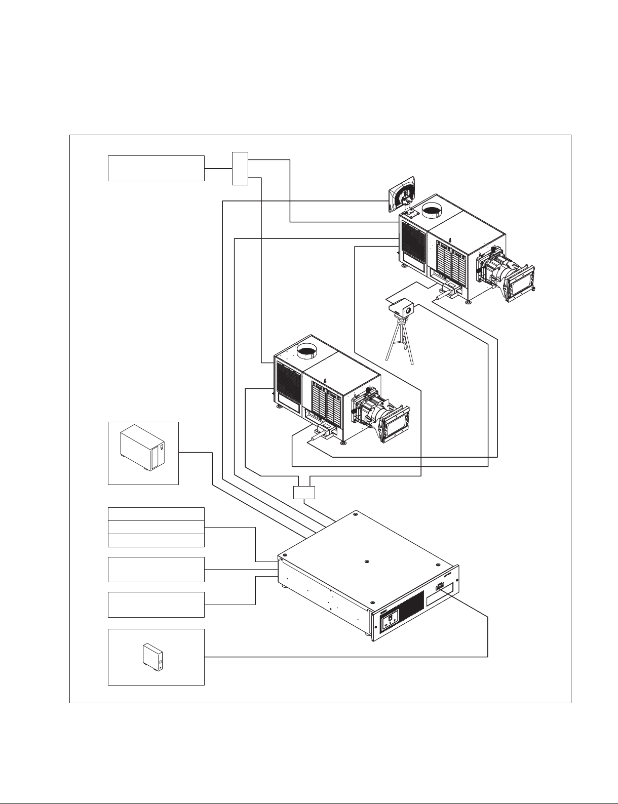
1-1. System Configuration Example
Section 1
Device with external video
(HDMI)
HDMI distributor
USB 2.0
HDMI
Sub-projector
RS-232C
D-sub 9 pin
CTRL1
VGA,USB 2.0
Touch panel monitor
Main projector
RS-232C
D-sub 9 pin
CTRL2
Projector auto
calibration box
(hereafter referred
to as “Calibration
camera”)
Conduit
UPS
Automation system
Lighting controller
Curtain controller
Audio processor
Theater network (LAN)
Video signal, audio data
USB HDD
GPIO
RS-232C
D-sub 9 pin
LAN
USB 2.0/3.0
HUB
Digital cinema server
(hereafter referred to as “Server”)
Digital Cinema Dual System
1-1 (E)

System configuration of dual system
SRX-R515P is used as the main projector and SRX-R515 is used as the sub-projector. When viewed from
the back side (touch panel monitor side), the projector that has the AUDIO OUTPUT terminal at the
connection on the right side is SRX-R515P and the projector that does not have the AUDIO OUTPUT
terminal is SRX-R515.
In the 3D projection, the main projector displays the image of the left eye, and the sub-projector displays
the image of the right eye respectively.
The conduit consists of the conduit box and conduit cable.
n
. Dual system cannot work properly in one projector. In this system, the two projectors are supposed to
always operate simultaneously.
In the 2D projection, the same image is output from the two projectors. In the 3D projection, the image for
the left eye is output from one projector and the image for the right eye is output from the other projector.
. Be sure to use the lens of the same model for the two projectors.
. Attach the 3D filter for the left eye to the main projector and the 3D filter for the right eye to the sub-
projector.
. The image distortion correction data is saved in the function memory.
Therefore, perform the image distortion correction adjustments as many as the number of the registered
function memory.
1-2. Accessories
The following accessories are supplied with this system.
[Digital Cinema Projector SRX-R515]
. Key for removing panels (5) . TPC arm (1 set)
. Safety regulations (1) . Cable clamper (2)
[Digital Cinema Server XCT-S10]
. Feet (1 set) . Ethernet cable (2 m) (1)
. PCI express cable (2 m) (1)
[Touch Panel Monitor LKRA-007]
. AC adaptor (1) . VGA cable (1)
. USB cable (1)
[Dual System Accessory Kit LKRA-010]
. Tamper harness (3)
. Conduit box mounting screw (K2.6 x 5) (4)
. Conduit support mounting screw (bolt 8 x 12) (4)
[3D filter and Holder LKRA-011]
. Filter bracket mounting screw M8 (8) . Hexagonal spacer (8)
. Filter mounting screw M4 (8) . Washer (8)
. Spring washer (8)
[Projector Auto Calibration Box LKRA-PCAB1]
. AC adaptor (1) . Connecting cable (2)
1-2 (E)
Digital Cinema Dual System

1-3. Required Equipment/Tools
The equipment and tools required for this system are as follows.
Equipment/tools Description
Projection lens Prepare the necessary lens(es) in accordance with the installation
environment.
. LKRL-Z511
. LKRL-Z514
. LKRL-Z519
t
. Be sure to use the lens of the same model for the two projectors.
. Regarding the selection of lens, contact your local Sony Sales Office/Service Center.
Lamp Prepare one of the following lamps in accordance with the installation environment.
. LKRM-U450 (6 pcs, 450 W)
. LKRM-U331 (6 pcs, 330 W)
. LKRM-U330 (6 pcs, 330 W)
n
. If all of the above number of lamps are not inserted, the projector does not operate.
. Do not mix two different lamp types (i.e., 330 W and 450 W) in a projector.
If you do so, an error will occur and the projector will not start up.
Insert the lamps of the same number and the same model in the main projector
and sub-projector.
. Regarding the selection of lamp, contact your local Sony Sales Office/Service Center.
Dual system accessory kit LKRA-010
Required to configure the dual system.
3D filter and holder LKRA-011
Required to project the 3D images.
For attaching the 3D filter and holder, the following tools are also required.
. Long screwdriver (Phillips-head)
. Socket wrench (subtense: 13 mm)
Calibration camera LKRA-PCAB1
Corrects the misalignment of convergence between the two projectors.
An alignment DCP is also required. (Refer to Section 6.)
Update package Prepare all of the following software modules to configure the dual system.
. Unified Update Manager (UUM)
. Module to make the system to be recognized as the dual system
. Module to update the software to the latest version
Hub Cisco 2960CG-8TC-L or the equivalent
To prevent an instantaneous breakdown, the switching hub should obtain power from
UPS in the same way as XCT-S10.
Pedestal _
UPS For the server
Power cable Prepare the cable that matches the plug on the installation site.
Exhaust system Connect the duct to the duct connecting portion on the rear top panel for exhausting
the heat inside the projector. In the case of using the 8-inch duct, the following exhaust
air volume is required.
The exhaust air volume of 450-550 ft
External connection cable Refer to Section 4.
Tool Screwdriver (for installing the lamp and server)
Carrying handle Handle arm (part number: 4-164-849-02)
Pipe (short) (part number: 4-164-850-02)
Pipe (long) (part number: 4-164-851-02)
Luminance meter CL-200 or the equivalent
Colorimeter PR-650 or the equivalent
3
/min (12.7 to 15.6 m3/min) should be secured.
Digital Cinema Dual System
1-3 (E)

Equipment/tools Description
Tripod For the colorimeter and illuminometer
Hexagonal wrench For the lens shift adjustment: subtense: 5.0 mm
Spanner Subtense: 8 mm (supplied with the lens)
Subtense: 24 mm (for flexible leveler)
Subtense: 30 mm (for nut (M20))
USB mouse, USB keyboard For the connection setting with the external equipment such as audio processor and
UPS
LTC cable Required only when configuring the 4D system. (Refer to Section 7.)
LTC converter Prepare the LTC converter and Ethernet cable as required.
Ethernet cable
1-4 (E)
Digital Cinema Dual System
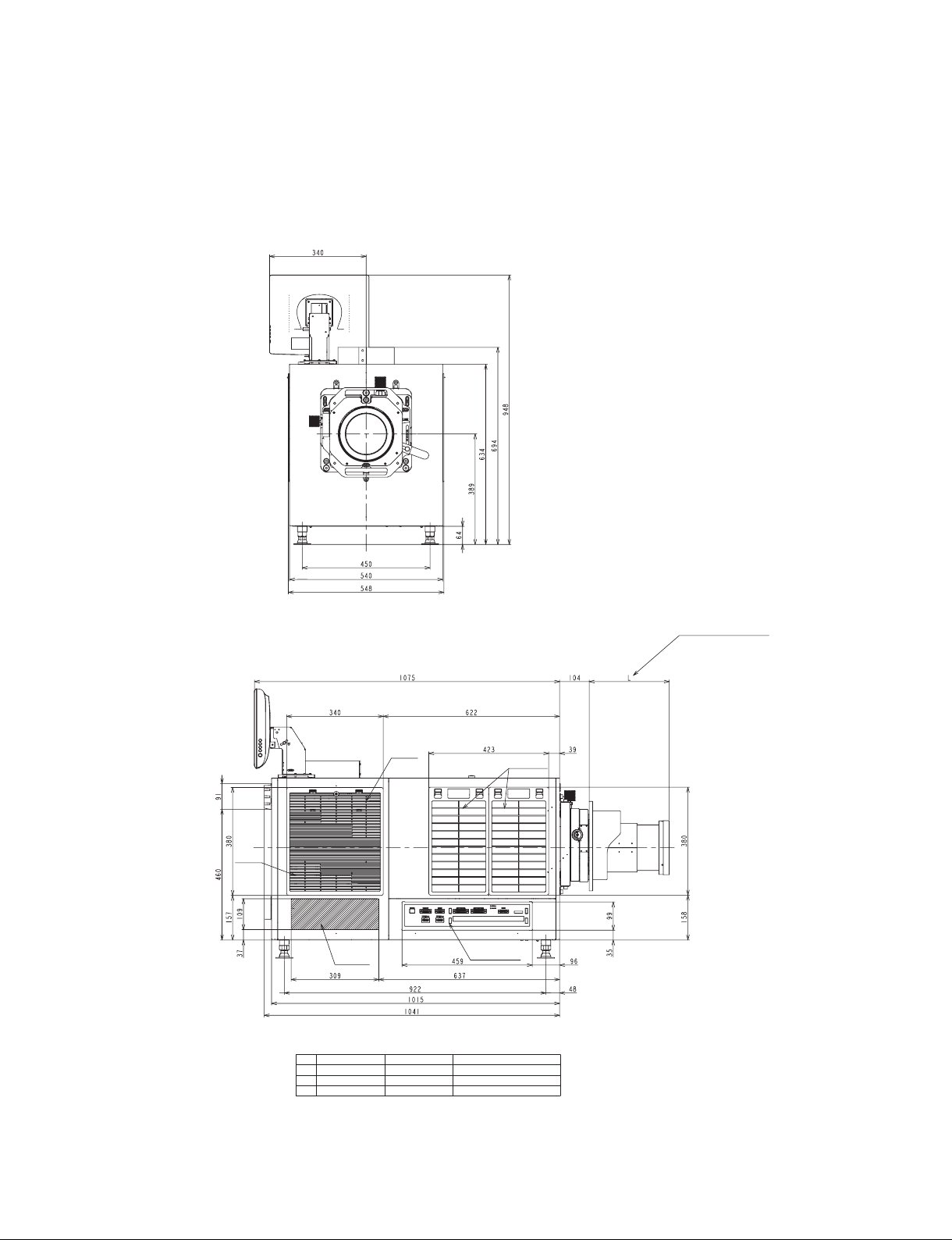
1-4. External Dimensions
1-4-1. Projector
Front view
Left side view
Air
Intake
Air
Intake
Heat
exhaust
Input/output
terminal
*
LKRL LIST
No. LKRL L REMARKS
1 Z511 258-297
2 Z514 230-283
3 Z519 244
*
(Refer to the optional
lens list.)
Air Intake
Digital Cinema Dual System
1-5 (E)
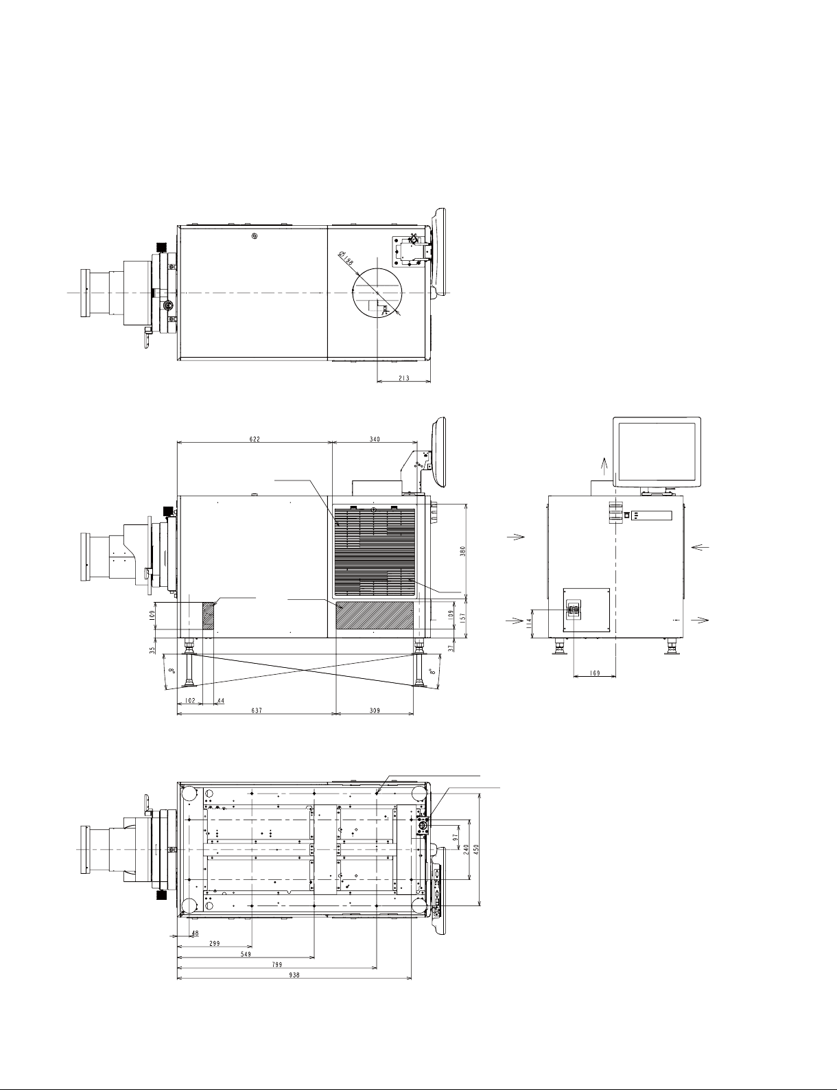
Top view
Right side view Rear view
Bottom view
Air Intake
Air Intake
Air Intake
Air
Intake
10-M8 (for fixing the projector)
AC power cable
Air Intake
Air Intake
Heat exhaust
Air Intake
Heat exhaust
1-6 (E)
Unit: mm
Digital Cinema Dual System
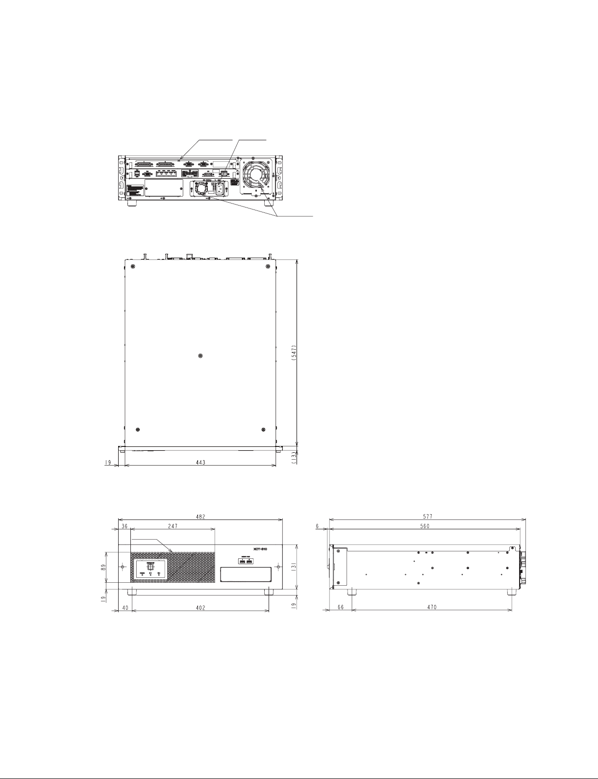
1-4-2. Server
Rear view
Top view
Input/output
terminal
AC power
cable
Heat exhaust
Front view
Air Intake
Digital Cinema Dual System
Right side view
Unit: mm
1-7 (E)
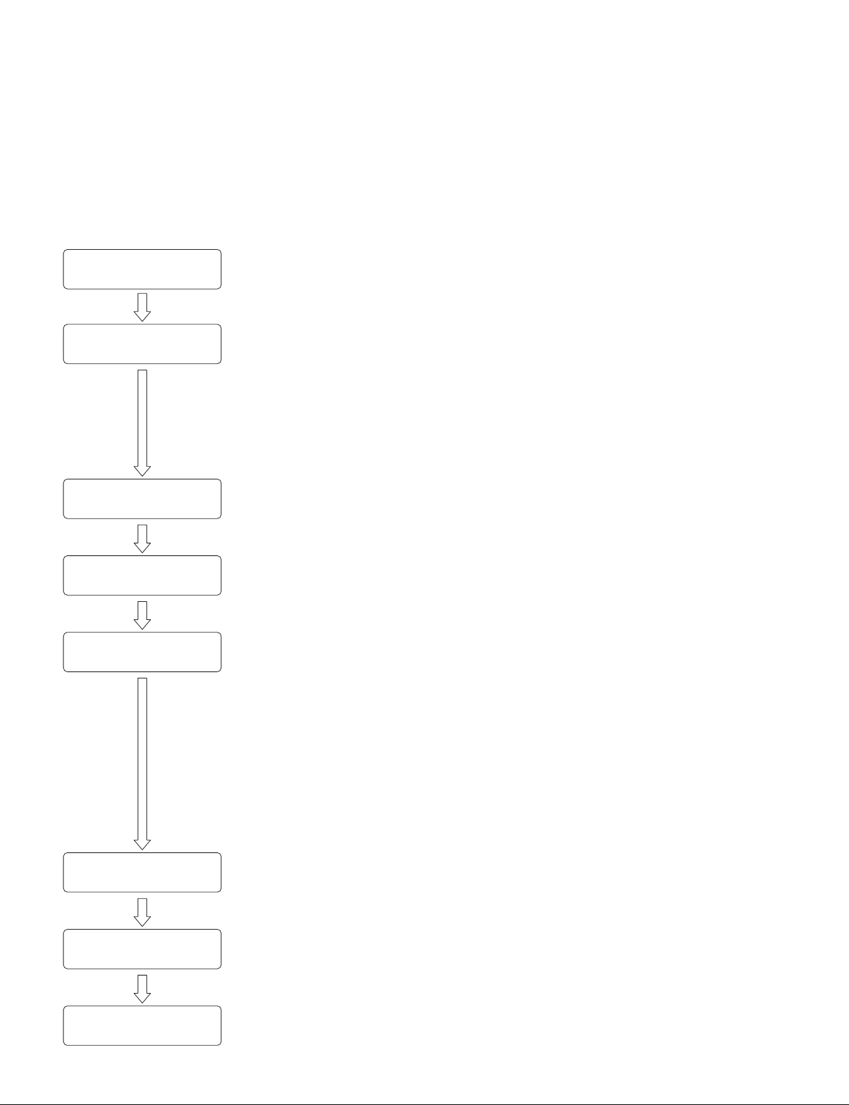
1-5. Installation Flow
The installation procedure for this system is shown in the flow chart.
For the details of each flow, refer to the corresponding item.
n
Basically there is no problem even if Sections 2-1 to 2-4 are not performed in sequential order. However,
do not connect the power cord in Section 2-5 before Sections 2-1 to 2-4 are completed.
Start the installation.
Install the projector.
(Refer to Section 2.)
Install the server.
(Refer to Section 3.)
Connect the external equipment.
(Refer to Section 4.)
Setting and adjustment
after the connection.
(Refer to Section 5.)
Installation/Adjustment of the
LKRA-PCAB1
(
Refer to Section 6.)
. 2-1. Installation of Duct
. 2-2. Installation of Lens
. 2-3. Installation of Lamp
. 2-4. Installation of Touch Panel Monitor
. 2-5. Connection of Power Cord
. 2-6. Adjustment of Projector Tilt
. 2-7. Installation of Dual System Accessory Kit (LKRA-010)
. 2-8. Installation of 3D Filter and Holder (LKRA-011)
. 3-1. Installation of Server
. 3-2. Connection with Projector
. 3-3. Power Connection
. 3-5. Installation of CRU DATAPORT Carrier
. 5-1. Update to Dual System Software
. 5-2. System Startup and Login
. 5-4. Initial Setting
. 5-5. Performing the Marriage
. 5-6. Projector Startup
. 5-7. Image Adjustment Flow
. 2-8-4. Check/Adjustment of 3D Filter Position
. 5-8. Image Adjustment
. 5-9. Color Space Conversion (CSC) Adjustment
. 5-10. Check of Video Signal and Audio Output
. 5-11. Network Setting
. 5-12. Folder Setting
. 5-13. Setting of External Equipment
. 5-14. Other Settings
. 5-15. Operating This System Using a Personal Computer (PC)
. 5-16. Shutdown
Connect with the 4D system.
(Only when it is required)
(Refer to Section 7.)
The installation is completed.
1-8 (E)
Digital Cinema Dual System
1-6. Installation of Carrying Handle
When moving the projector to the pedestal after unpacking, attach the carrying handles as required for
transporting it.
n
The carrying handles cannot be attached to both back/forth and right/left at the same time.
Parts information
. Handle arm: 4-164-849-02: 4 pcs
. Pipe (short): 4-164-850-02: 2 pcs
. Pipe (long): 4-164-851-02: 2 pcs
. M8 bolt: 2-590-262-02 or -11: 4 pcs
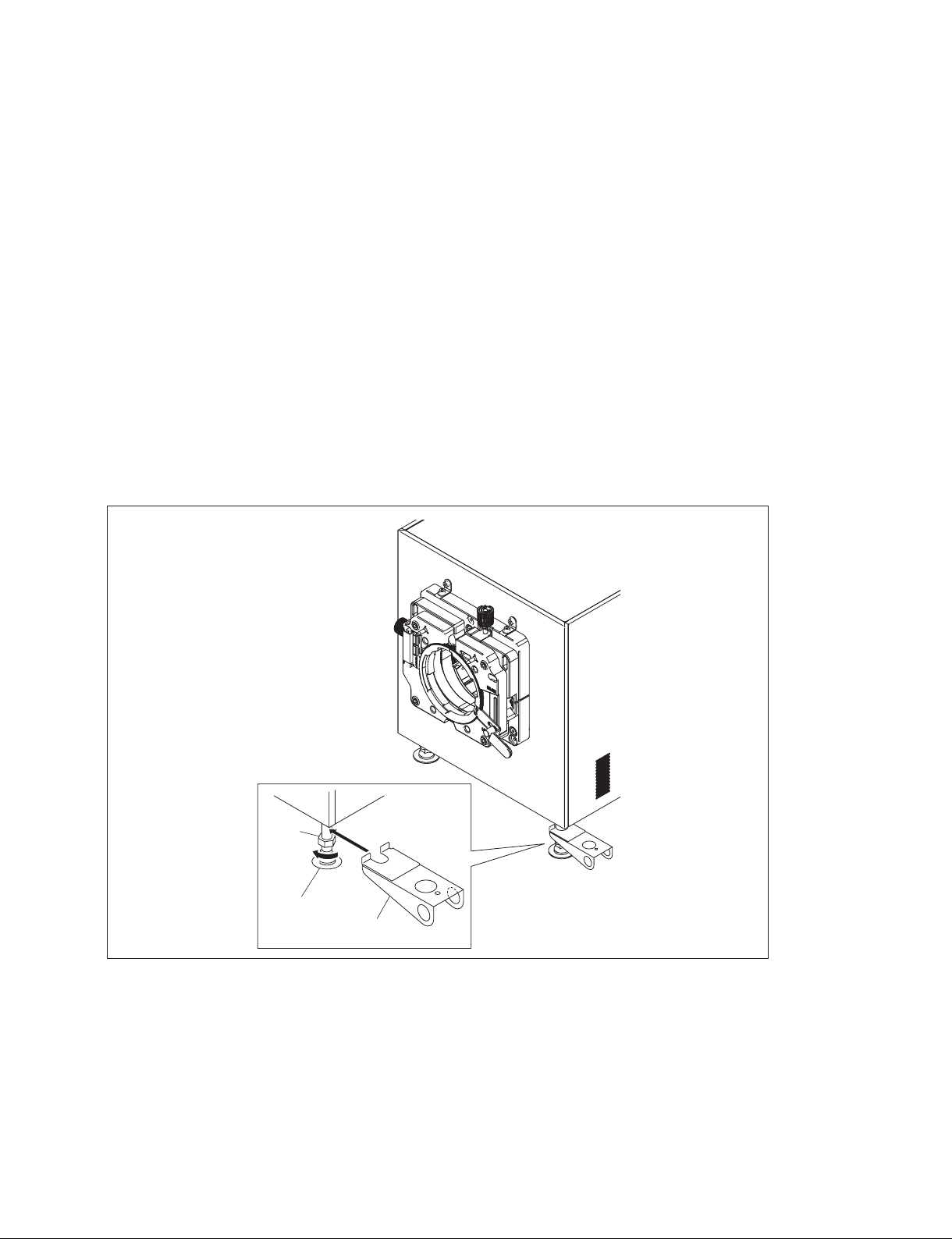
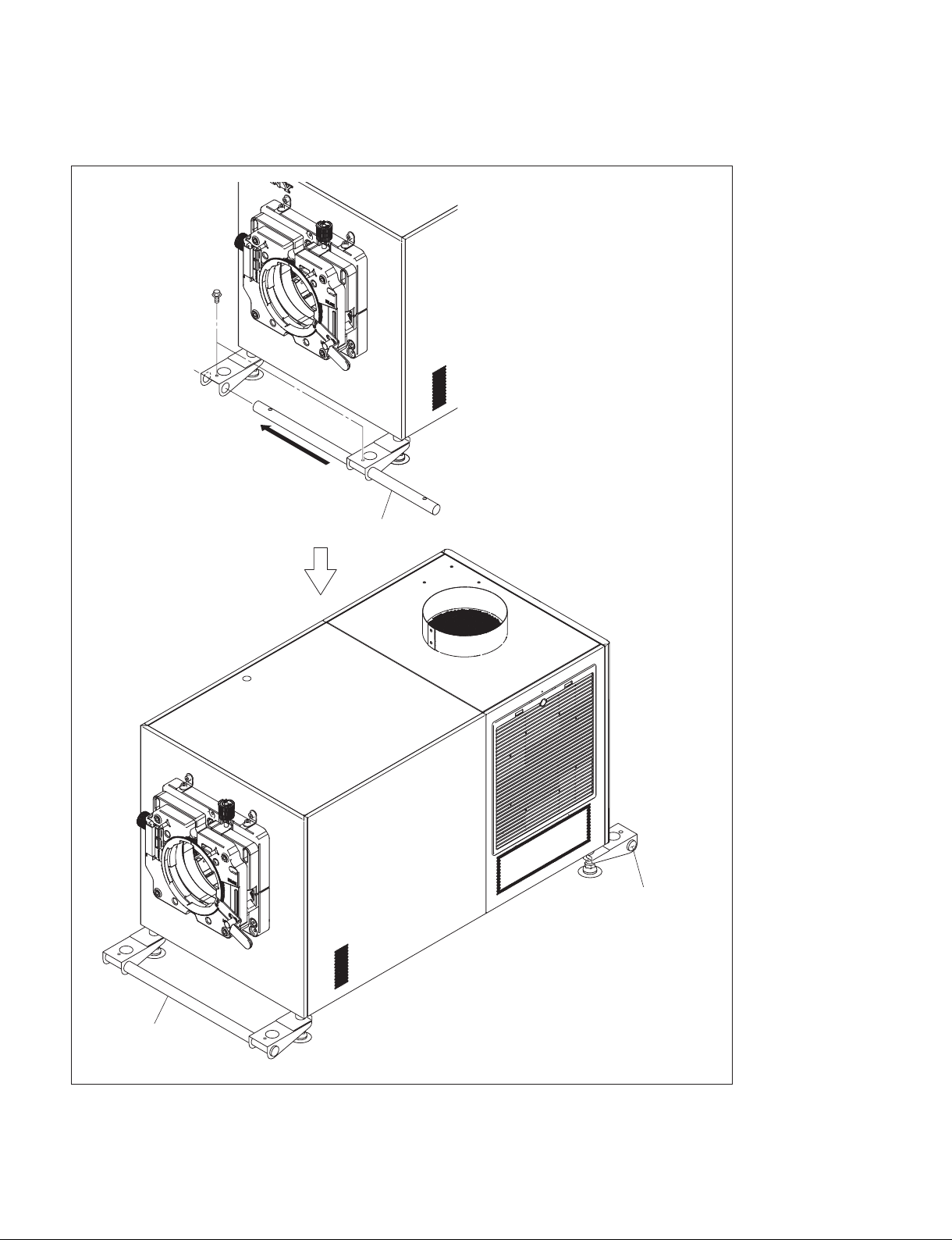
In the case of attaching the pipe (long) to the right and left side of projector
1. Loosen the nut in the direction of the arrow A, then insert the handle arm in the direction of the
arrow B.
2. Tighten the nut to fix the handle arm.
3. Attach the handle arm to the adjuster of other three portions by repeating steps 1 and 2.
Digital Cinema Dual System
Nut
A
Adjuster
B
Handle arm
1-9 (E)
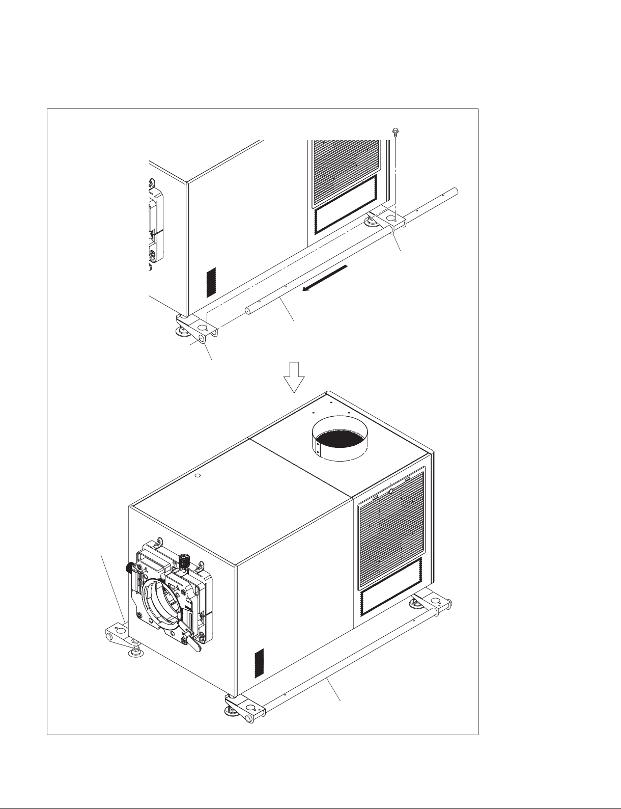
4. Insert the pipe (long) into the handle arms, then fix the pipe with the two M8 bolts.
5. Attach the pipe (long) on the other side in the same way.
M8 bolts
Handle arm
Pipe (long)
Handle arm
Pipe (long)
1-10 (E)
Pipe (long)
Digital Cinema Dual System
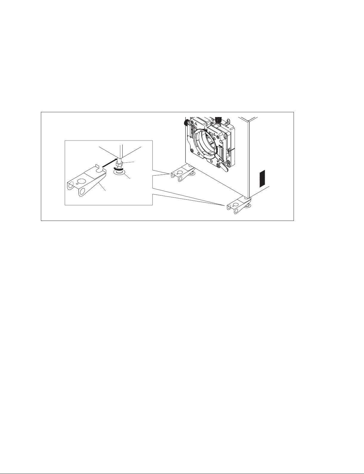
In the case of attaching the pipe (short) to the back and forth of projector
t
The procedure is the same as the pipe (long).
1. Loosen the nut in the direction of the arrow A, then insert the handle arm in the direction of the
arrow B.
2. Tighten the nut to fix the handle arm.
3. Attach the handle arm to the adjuster of other three portions by repeating steps 1 and 2.
B
Handle arm
Nut
A
Adjuster
Digital Cinema Dual System
1-11 (E)
4. Insert the pipe (short) into the handle arms, then fix the pipe with the two M8 bolts.
5. Attach the pipe (short) on the other side in the same way.
M8 bolts
Pipe (short)
1-12 (E)
Pipe (short)
Pipe (short)
Digital Cinema Dual System
Section 2
Installation of Projector
n
Basically there is no problem even if Sections 2-1 to 2-4 are not performed in sequential order. However,
do not connect the power cord in Section 2-5 before Sections 2-1 to 2-4 are completed.
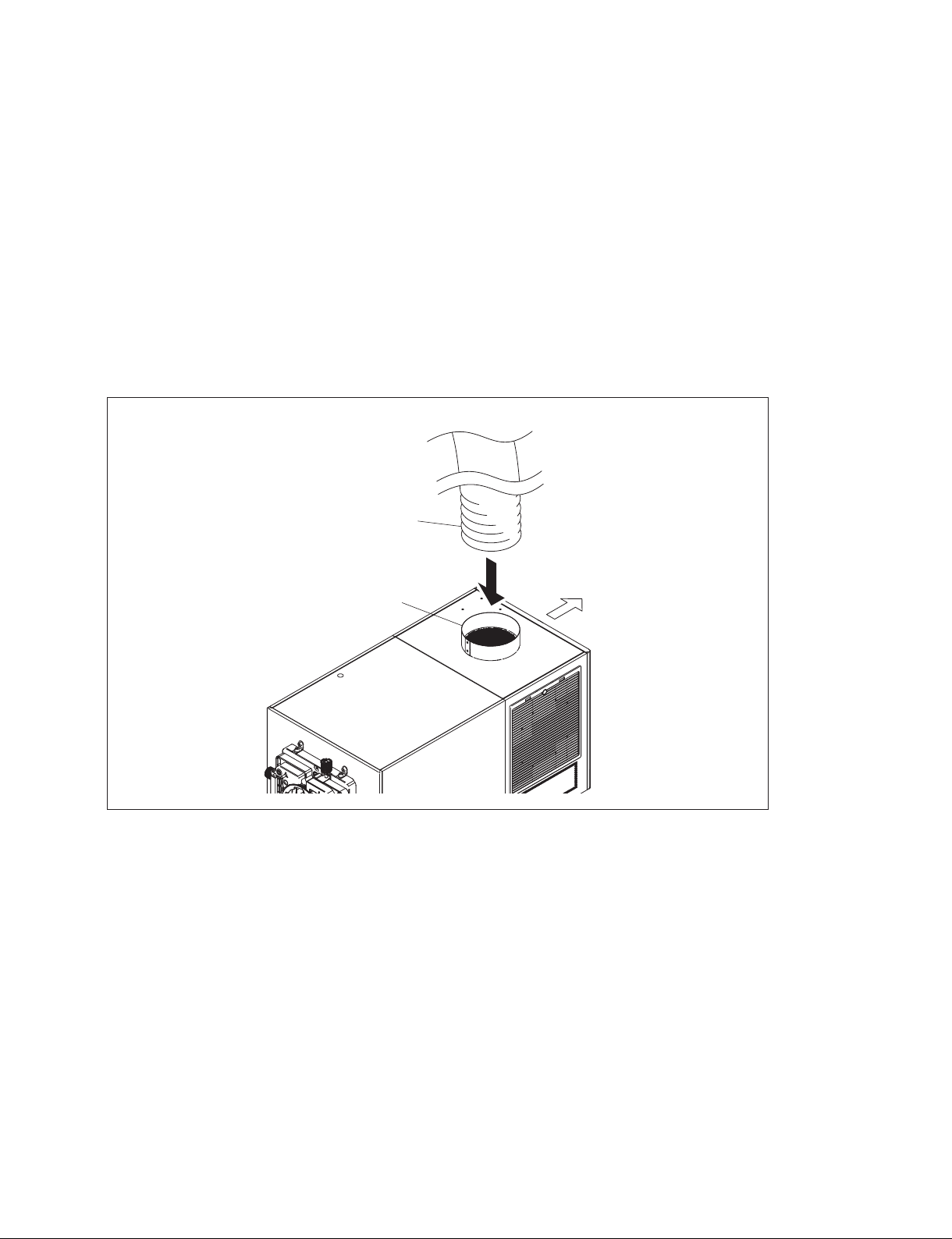
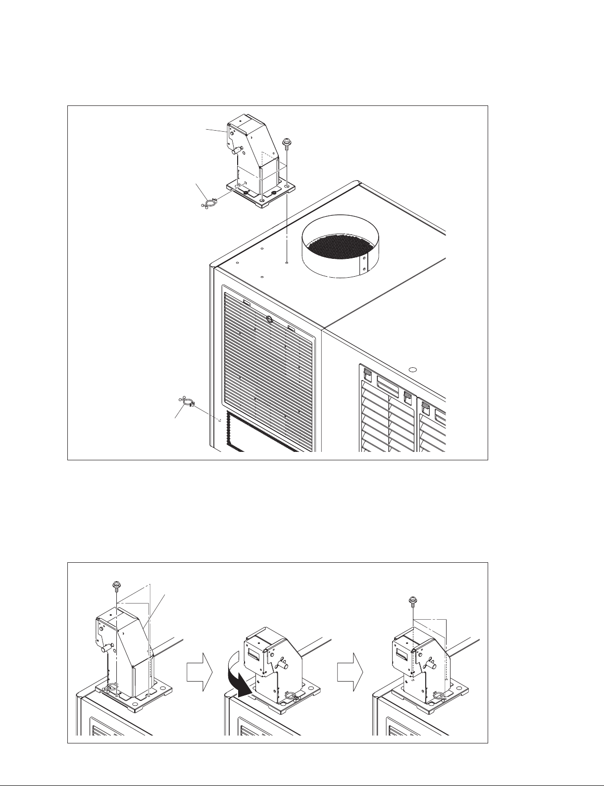
2-1. Installation of Duct
Attach the 8-inch duct to the duct connecting portion on the rear side of the projector top portion.
n
. When attaching the duct, be careful not to bend the duct for exhausting the air smoothly.
. For the required exhaust air volume, refer to “1-3. Required Equipment/Tools”.
8-inch duct
Duct connecting portion
Rear side
Digital Cinema Dual System
2-1 (E)
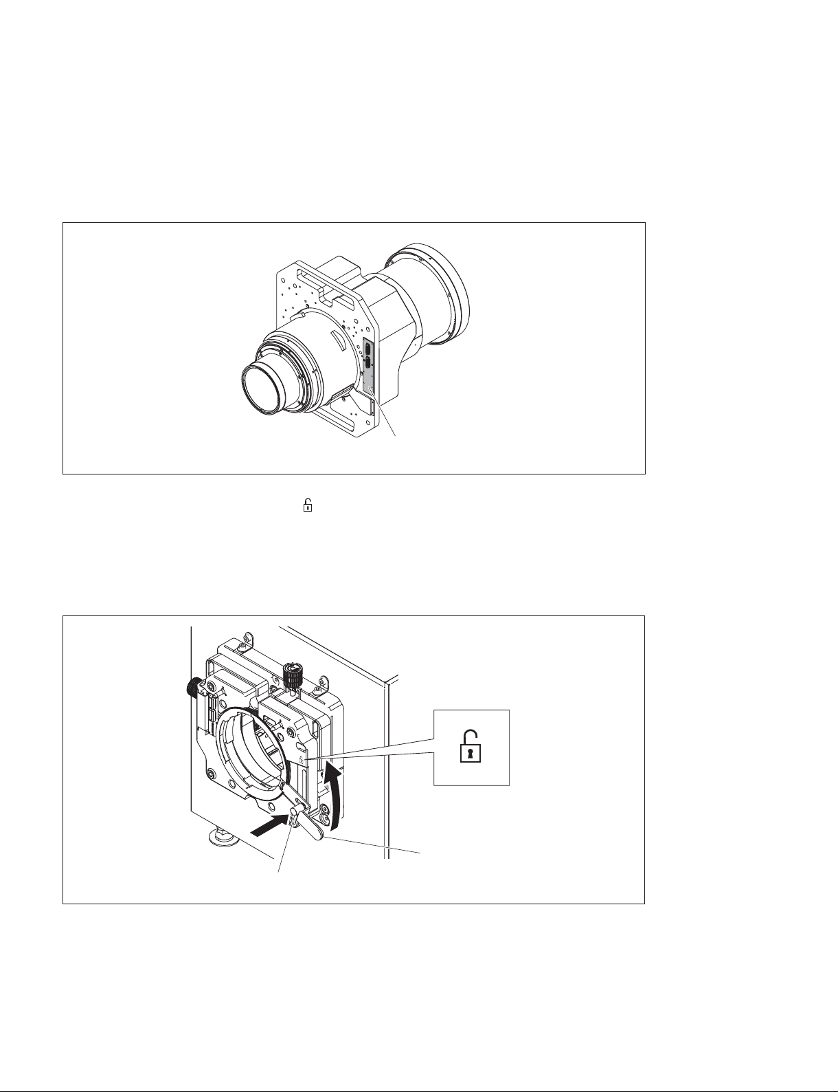
2-2. Installation of Lens
n
. When performing the installation/removal of lens, be sure to shut down the system, then turn off the
power switch on the rearof the projector.
. When performing the installation/removal of lens, be careful not to touch the lens board.
Board
1. Raise the lens fixing lever toward the “ ” side with the lock button pushed all the way in (lock
released).
n
If you raise the lens fixing lever without pushing the lock button, the lock button and lens fixing lever
will be damaged. Be sure to push the lock button and check that the lock is released before raising the
lever.
2-2 (E)
Lens fixing lever
Lock button
Digital Cinema Dual System
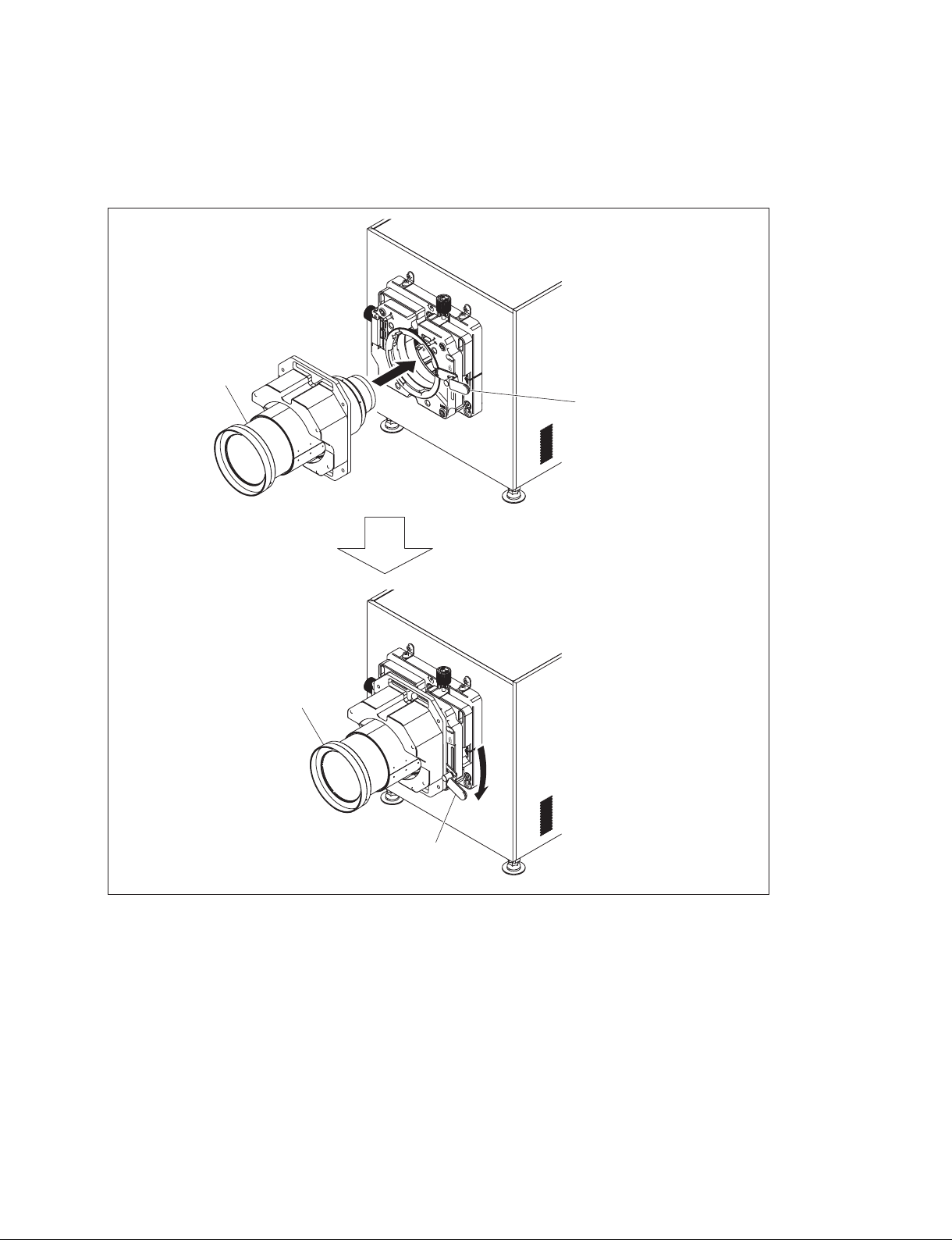
2. Attach the lens to the projector while firmly holding the lens not to drop it and aligning the position.
n
When attaching the lens to the projector, insert it straight.
3. Lower the lens fixing lever to fix the lens.
Lens
Lens fixing lever
Lens
Lens fixing lever
Digital Cinema Dual System
2-3 (E)
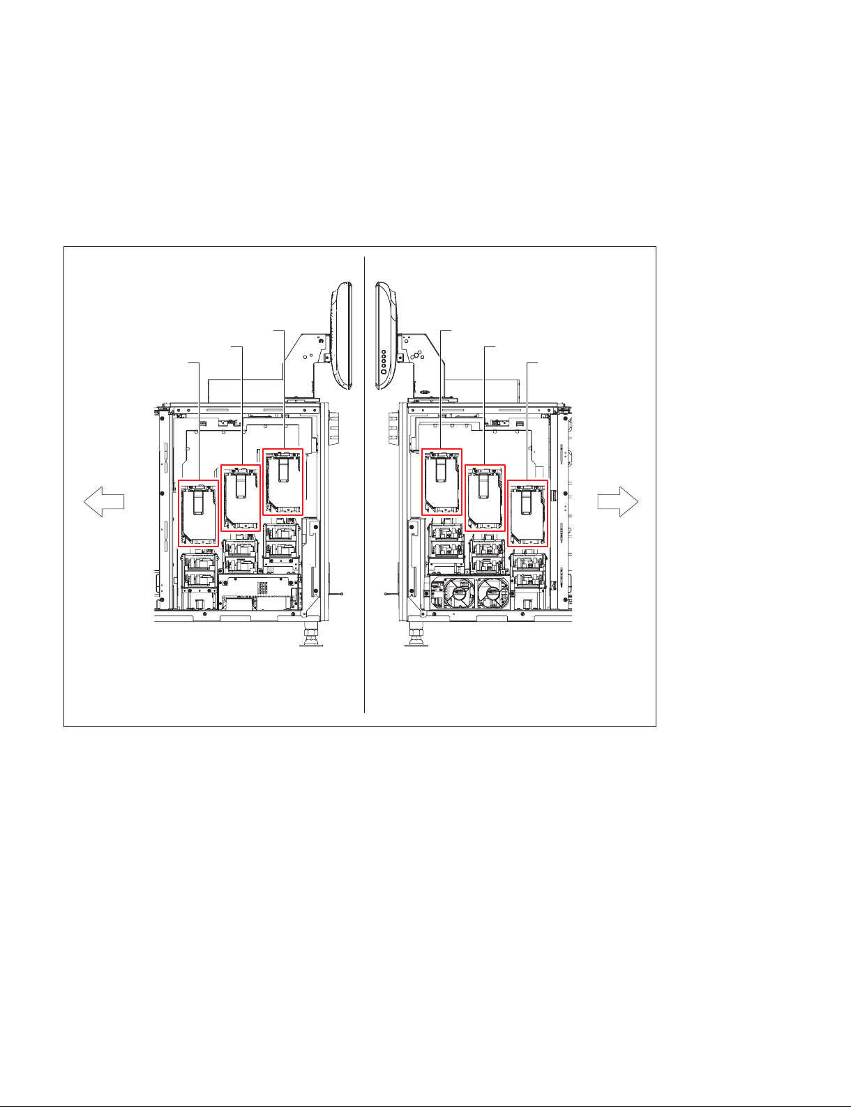
2-3. Installation of Lamp
n
. For safety, always wear gloves when performing installation.
. Install the six lamps on SRX-R515P/R515.
. Do not mix two different lamp types (i.e., 330 W and 450 W) in a projector. If you do so, an error will
occur and the projector will not start up.
Left side of projectorRight side of projector
Front side of
projector
A1 lamp
A2 lamp
A3 lamp
B3 lamp
B2 lamp
B1 lamp
Front side of
projector
2-4 (E)
Digital Cinema Dual System
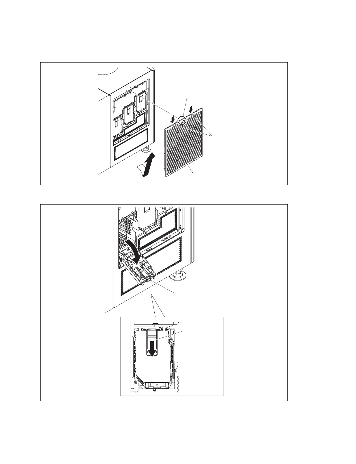
1. Loosen the screw (with drop-safe), lower the two hooks, and then remove the intake grille (A) in the
direction of the arrow A.
Screw (with drop-safe)
Hooks
A
2. Lower the lamp door latch to open the lamp door.
Intake grille (A)
Lamp door
Lamp door latch
Digital Cinema Dual System
2-5 (E)
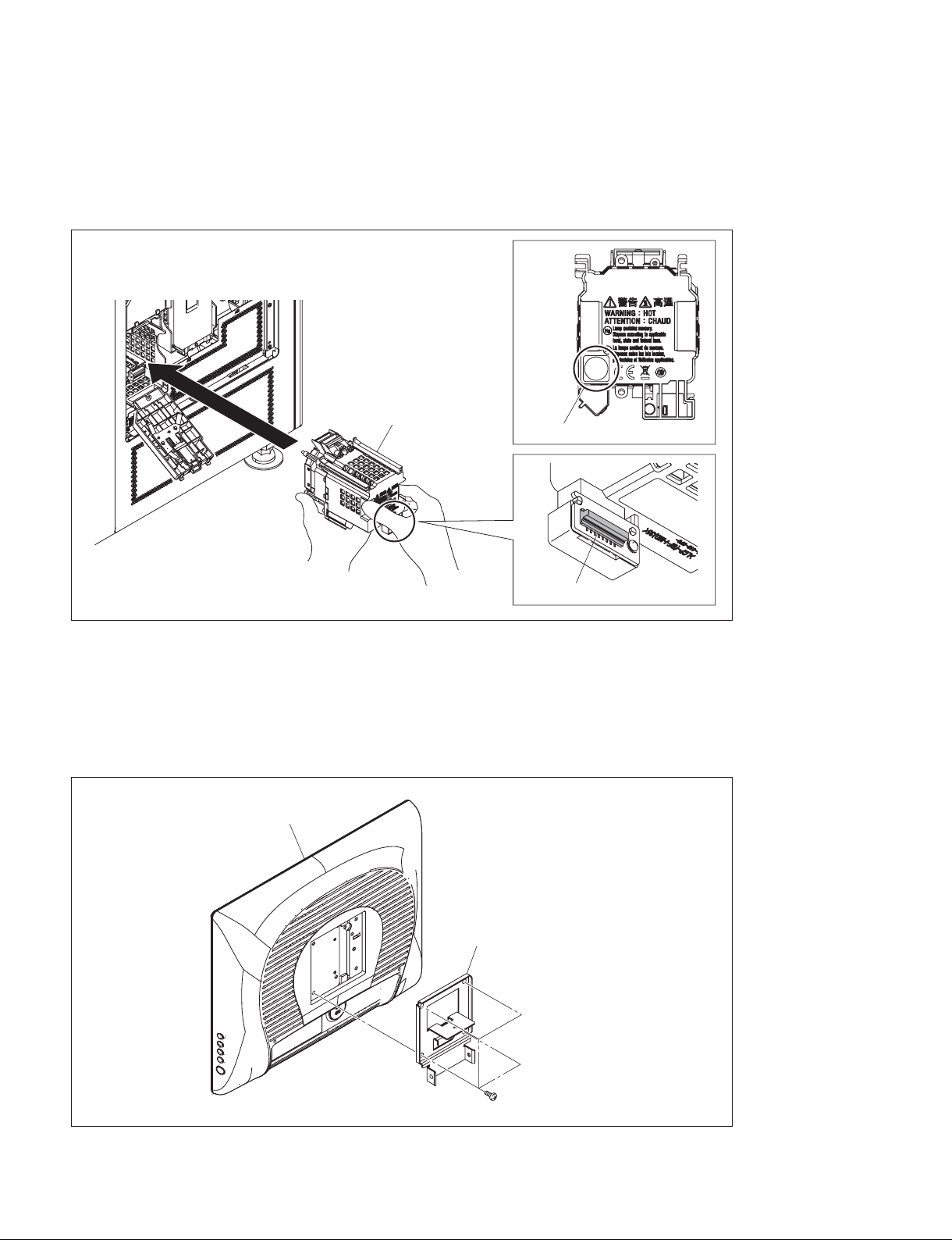
3. Insert the lamp and close the lamp door.
n
. When holding the lamp, be careful not to touch the connector contact portion.
. Push near the PUSH mark of the lamp to insert it securely.
4. Attach the remaining lamps by repeating steps 2 and 3.
PUSH
Lamp
5. To install the intake grille (A), reverse the removal procedure.
2-4. Installation of Touch Panel Monitor
1. Attach the TPC mounting plate with the four screws.
Touch panel monitor
PUSH mark
Connector contact portion
2-6 (E)
TPC mounting plate
Screws
Digital Cinema Dual System
2. Attach the TPC arm block assembly with the four screws.
3. Attach the two cable clampers.
TPC arm block assembly
PSW4 x 10
Cable clamper
Cable clamper
t
The direction of the touch panel monitor can be changed by rotating the TPC arm block assembly.
(1) Remove the three screws.
(2) Rotate the TPC arm block assembly in the direction of the arrow.
(3) Fix the TPC arm block assembly with the three screws.
PSW4 x 10
TPC arm block assembly
PSW4 x 10
Digital Cinema Dual System
2-7 (E)
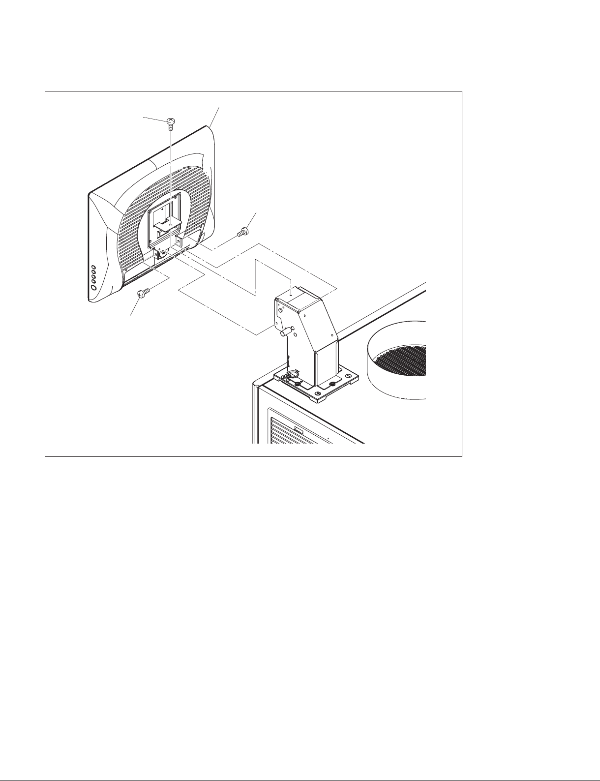
4. Attach the touch panel monitor with the three screws.
Touch panel monitor
Screw
Screw
Screw
2-8 (E)
Digital Cinema Dual System
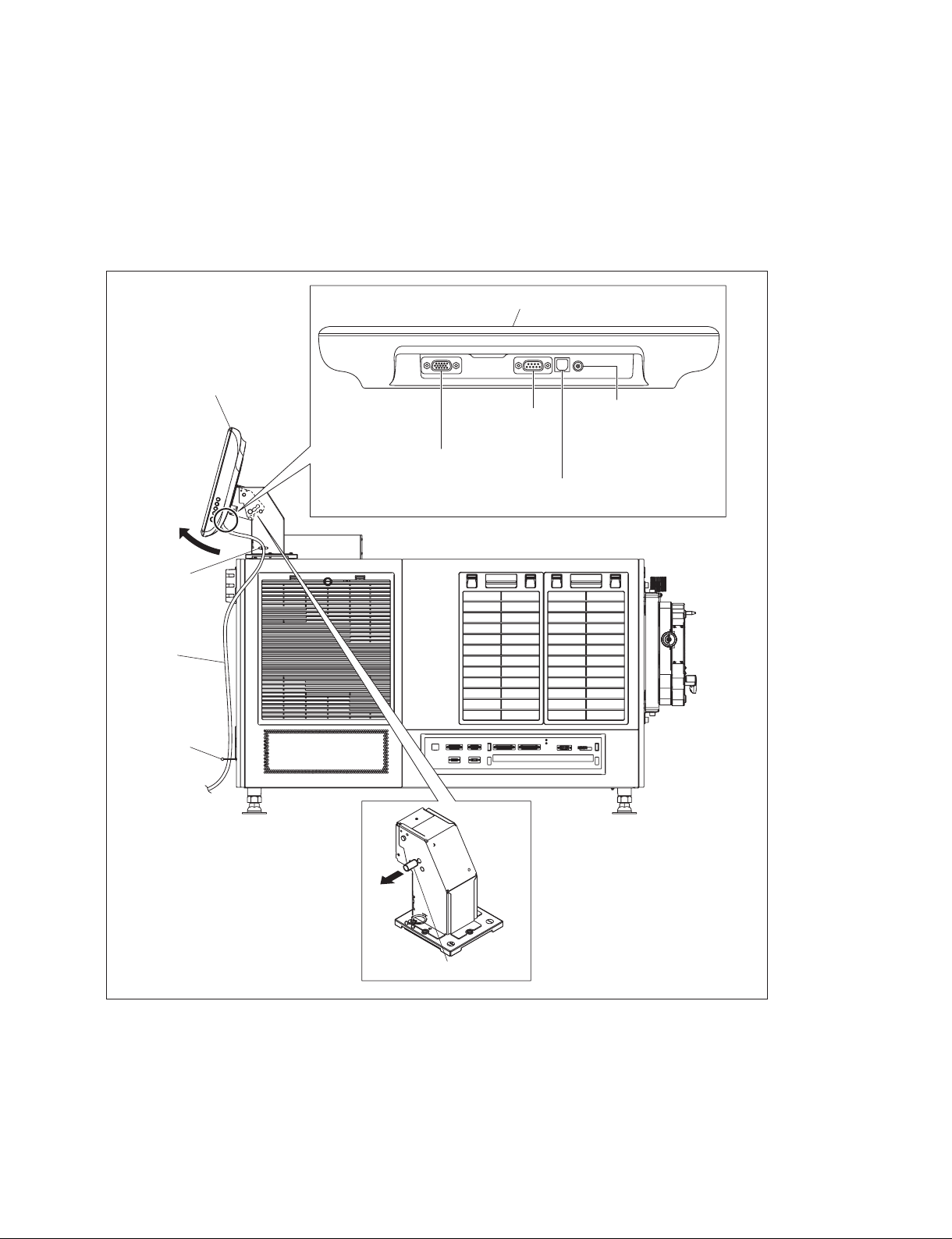
5. Pull the knob and tilt the touch panel monitor in the direction of the arrow.
t
When you pull the knob, the touch panel monitor can be moved, and when you release the knob, the
touch panel monitor is fixed.
6. Connect each cable to the connector on the bottom of the touch panel monitor.
7. Fix the cable with the two cable clampers.
8. Pull the knob and return the tilt of the touch panel monitor to the original position.
Touch panel monitor
Touch panel monitor
RS-232C terminal
(for service)
VGA terminal: VGA cable (accessory)
(To the VGA terminal of the server)
TPC terminal: USB cable (accessory)
(To the TPC terminal of the server)
Cable clamper
Power input terminal:
AC adaptor cable
(accessory)
(To the AC adaptor)
Cable
Cable clamper
Knob
Digital Cinema Dual System
2-9 (E)
2-5. Connection of Power Cord
Use the 3-core power cord that satisfies AWG 8, 250 V rated and 40 A rated or more.
Connect the power cord to the AC IN terminal block on the rear side of the projector in the following
procedure.
w
. Connection of the main power and the electric wiring work should be done by qualified electricians only.
. Do not plug the power cord into the power supply before completing all of the following connecting
operations.
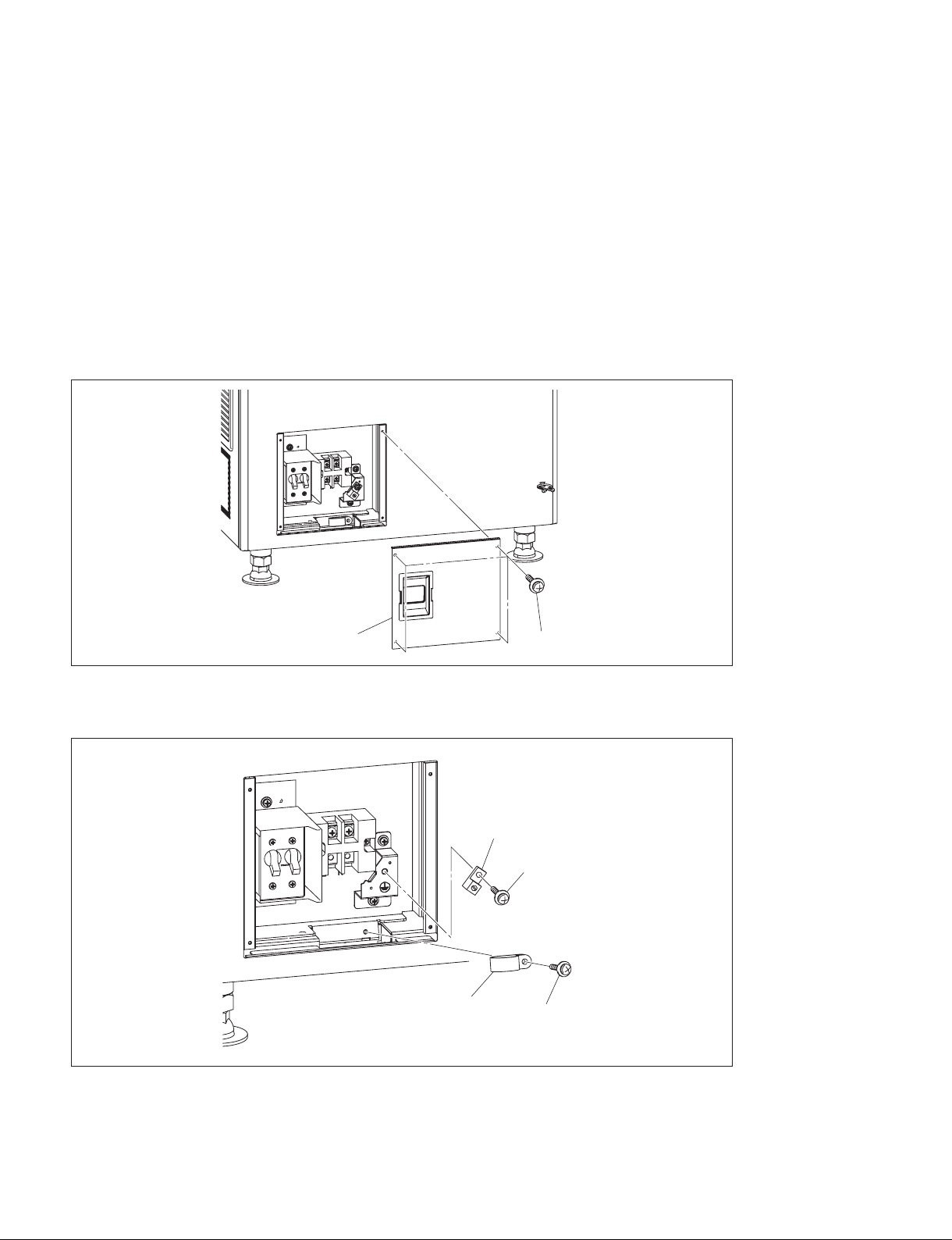
1. Remove the four screws, then remove the terminal block cover.
Terminal block cover
2. Remove the screw, then remove the cable clamp.
3. Remove the screw, then remove the ground terminal.
Ground terminal
Cable clamp
Screws
Screw
Screw
2-10 (E)
Digital Cinema Dual System
Loading...