


LMD-440

4-095-793-02 (1)
LCD Monitor
© 2003 Sony Corporation
LMD-440
LMD-530
LMD-720W
取扱説明書 _____________________________________________
JP
Operating Instructions ____________________________________
GB
Mode d’emploi __________________________________________
FR
Bedienungsanleitung _____________________________________
DE
Manual de instrucciones ___________________________________
ES
Istruzioni per l’uso ________________________________________
IT
_____________________________________________
CS
お買い上げいただきありがとうございます。
電気製品は安全のための注意事項を守らないと、
火災や人身事故になることがあります。
この取扱説明書には、事故を防ぐための重要な注意事項と製品の取り扱いかたを示してあり
ます。この取扱説明書をよくお読みのうえ、製品を安全にお使いください。お読みになった
あとは、いつでも見られるところに必ず保管してください。
JP
2
安全のために
ソニーのモニターは正しく使用すれば事故が起きないよ
うに、安全には十分配慮して設計されています。しかし、
内部に非常に高い電圧を使用しているので、まちがった
使いかたをすると、火災や感電などにより死亡や大けが
など人身事故につながることがあり、危険です。
事故を防ぐために次のことを必ずお守りください。
安全のための注意事項を守る
4 〜 5 ページの注意事項をよくお読みください。製品全
般の安全上の注意事項が記されています。
6 ページの「使用上のご注意」も併せてお読みください。
定期点検をする
5 年に 1 度は、内部の点検を、お買い上げ店またはソ
ニーのご相談窓口にご依頼ください(有料)。
故障したら使わない
すぐに、お買い上げ店またはソニーのご相談窓口にご連
絡ください。
万一、異常が起きたら
a 電源を切ります。
b 電源コードや接続ケーブルを抜きます。
c お買い上げ店またはソニーのご相談窓口までご相談く
ださい。
・ 煙が出たら
・ 異常な音、においがしたら
・ 内部に水、異物が入ったら
・ 製品を落としたり、キャビネットを破損したと
きは
この装置は、情報処理装置等電波障害自主規制協議会
(VCCI) の基準に基づくクラス A 情報技術装置です。
この装置を家庭環境で使用すると電波障害を引き起こ
すことがあります。この場合には使用者が適切な対策
を講ずるよう要求されることがあります。
警告表示の意味
この取扱説明書および製品では、次のような表示
をしています。表示の内容をよく理解してから本
文をお読みください。
この表示の注意事項を守らないと、火災や感電な
どにより死亡や大けがなど人身事故につながるこ
とがあります。
この表示の注意事項を守らないと、感電やその他
の事故によりけがをしたり周辺の物品に損害を与
えたりすることがあります。
注意を促す記号
行為を禁止する記号
行為を指示する記号
3
JP
JP
目次
警告.........................................................................................4
注意.........................................................................................5
設置 ................................................................................................6
使用・設置場所について .......................................6
設置に関する注意とお願い ...................................6
ラックに取り付けるには .......................................6
使用上のご注意 ...........................................................................6
液晶画面について..................................................6
輝点・滅点について ..............................................6
お手入れのしかた..................................................6
電源接続について..................................................7
廃棄するときは .....................................................7
主な特長.......... ..............................................................................7
各部の名称と働き....................................................... ................8
前面.. ................... .................. ................... .............8
裏面.. ................... .................. ................... .......... 10
電源について ............................................................................11
保証書とアフターサービス...................................................12
保証書 ................................................................ 12
アフターサービス............................................... 12
主な仕様.......... ...........................................................................12
この取扱説明書について
本書では以下の機種について説明しています。
・LMD‑440(4型 )
・LMD‑530(5.6型 )
・LMD‑720W(7型 )
細かい違いについては本文中の説明をご覧ください。
JP
4
下記の注意を守らないと、火災や感電により死亡や大けがにつながること
があります。
キャビネットをはずさない、改造し
ない
内部には電圧の高い部分があり、キャビ
ネットや裏ぶたなどをはずしたり、改造し
たりすると、火災や感電の原因となります。
内部の調整や設定、点検、修理は、お買い
上げ店またはソニーのご相談窓口にご依頼
ください。
内部に水や異物を入れない
水や異物が入ると火災や感電の原因となり
ます。
万一、水や異物が入ったときは、すぐに電
源を切り、電源コードや接続ケーブルを抜
いて、お買い上げ店またはソニーのご相談
窓口にご相談ください。
電源コードを傷つけない
電源コードを傷つけると、火災や感電の原
因となります。
・ 設置時に、製品と壁やラック、棚などの
間に、はさみ込まない。
・ 電源コードを加工したり、傷つけたりし
ない。
・ 重いものをのせたり、引っ張ったりしな
い。
・ 熱器具に近づけたり、加熱したりしない。
・ 電源コードを抜くときは、必ずプラグを
持って抜く。
万一、電源コードが傷んだら、お買い上げ
店またはソニーのご相談窓口に交換をご依
頼ください。
規定の電源電圧で使う
この取扱説明書に記されている電源電圧で
お使いください(交流 100V)。
規定外の電源電圧での使用は、火災や感電
の原因となります。
油煙、湯気、湿気、ほこりの多い場所
では設置
•
使用しない
上記のような場所に設置すると、火災や感
電の原因となります。
この取扱説明書に記されている仕様条件以
外の環境での使用は、火災や感電の原因と
なることがあります。
3P‑2P 変換アダプターを使用しな
い
3P の電源プラグを 2P に変換するアダプ
ターは確実な設置・接続ができないため、
感電の原因となることがあります。
指定された方法でラックマウントす
る
ラックの取扱説明書に記載された方法以外
で本機をラックに取り付けると、落下して
故障やけがの原因となることがあります。
高温下では使用しない
高温の場所で本機を使用すると、発火、発
煙の原因となることがあります。
周囲温度が 35 ℃を超える場所や、直射日
光のあたる場所では使用しないでください。
6 ページの設置に関する注意とお願いの項
を合わせてお読みください。
5
JP
下記の注意を守らないと、けがをしたり周辺の物品に損害を与えることがあります。
接続の際は電源を切る
電源コードや接続ケーブルを接続するとき
は、電源を切ってください。感電や故障の
原因となることがあります。
指定された電源コード、接続ケーブ
ルを使う
付属の、あるいは取扱説明書に記されてい
る電源コード、接続ケーブルを使わないと、
感電や故障の原因となることがあります。
他の電源コードや接続ケーブルを使用する
場合は、お買い上げ店またはソニーのご相
談窓口にご相談ください。
水のある場所に設置しない
水が入ったり、ぬれたりすると、火災や感
電の原因となることがあります。雨天や降
雪中、海岸や水辺での使用は特にご注意く
ださい。
不安定な場所に設置しない
ぐらついた台の上や傾いたところなどに設
置すると、モニターが落ちたり、倒れたり
して、けがの原因となることがあります。
また、設置・取り付け場所の強度を充分に
お確かめください。
直射日光の当たる場所や熱器具の近
くに設置・保管しない
内部の温度が上がり、火災や故障の原因と
なることがあります。
真夏の、窓を閉め切った自動車内では 50
℃を越えることがありますので、ご注意く
ださい。
お手入れの際は、電源を切って電源
プラグを抜く
電源を接続したままお手入れをすると、感
電の原因となることがあります。
転倒、移動防止の処置をする
モニターをラックに取り付け・取りはずし
をするときは、転倒・移動防止の処置をし
ないと、倒れたり、動いたりして、けがの
原因となることがあります。安定した姿勢
で注意深く作業してください。
また、ラックの設置状況、強度を充分にお
確かめください。
ぬれた手で電源プラグに触らない
ぬれた手で電源プラグの抜き差しをすると、
感電の原因となることがあります。
移動させるときは電源コード、接続
ケーブルを抜く
接続したまま移動させると、電源コードや
接続ケーブルが傷つき、火災や感電の原因
となることがあります。
定期的に内部の掃除を依頼する
長い間掃除をしないと内部にホコリがたま
り、火災や感電の原因となることがありま
す。1 年に 1 度は、内部の掃除をお買い上
げ店またはソニーのご相談窓口にご依頼く
ださい(有料)。
特に、湿気の多くなる梅雨の前に掃除をす
ると、より効果的です。
入力アダプターを取り付ける際には
電源を切って電源プラグを抜く
入力アダプターを取り付ける際はモニター
の電源を切り、電源プラグを抜いてくださ
い。モニターに電源を接続したまま各種入
力アダプターを取り付けると感電の原因と
なることがあります。
電源プラグは突きあたるまで差し込
む
まっすぐに突きあたるまで差し込まないと、
火災や感電の原因となります。
DCIN 端子に規格以外の入力電圧
をかけない
DCIN 端子に規格以外の入力電圧をかける
と火災や感電の原因となることがあります。
設置/使用上のご注意
JP
6
設置
使用・設置場所について
次のような場所での使用・設置はお避けください。
・ 異常に高温になる場所
炎天下や夏場の窓を閉め切った自動車内はとくに高温に
なり、放置すると変形したり、故障したりすることがあ
ります。
・ 直射日光の当たる場所、熱器具の近く
変形したり、故障したりすることがあります。
・ 激しい振動のある場所
・ 強力な磁気のある場所
・ 砂地、砂浜などの砂ぼこりの多い場所
海辺や砂地、あるいは砂ぼこりが起こる場所などでは、
砂がかからないようにしてください。故障の原因になる
ばかりか、修理できなくなることがあります。
設置に関する注意とお願い
下記の注意事項を守らないと発火、発
煙の原因となるほか、製品寿命を低下
させる原因ともなります。
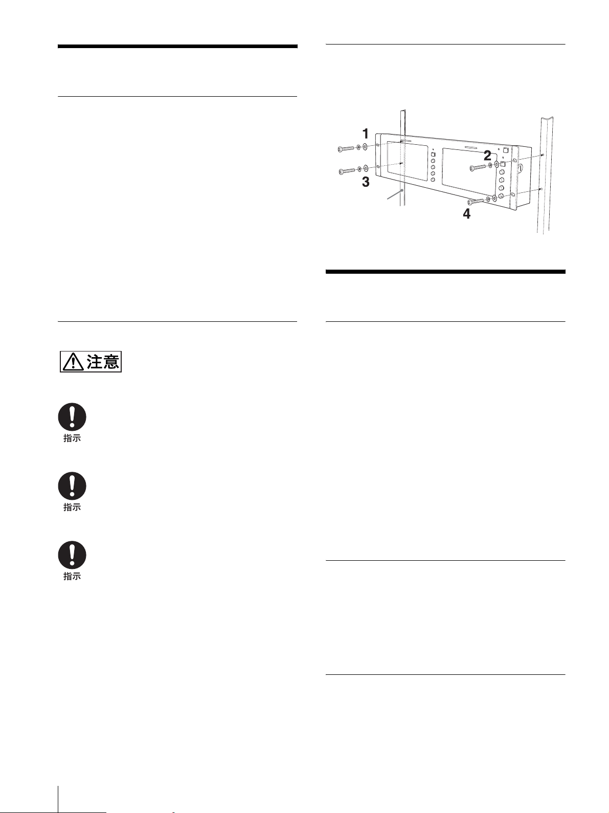
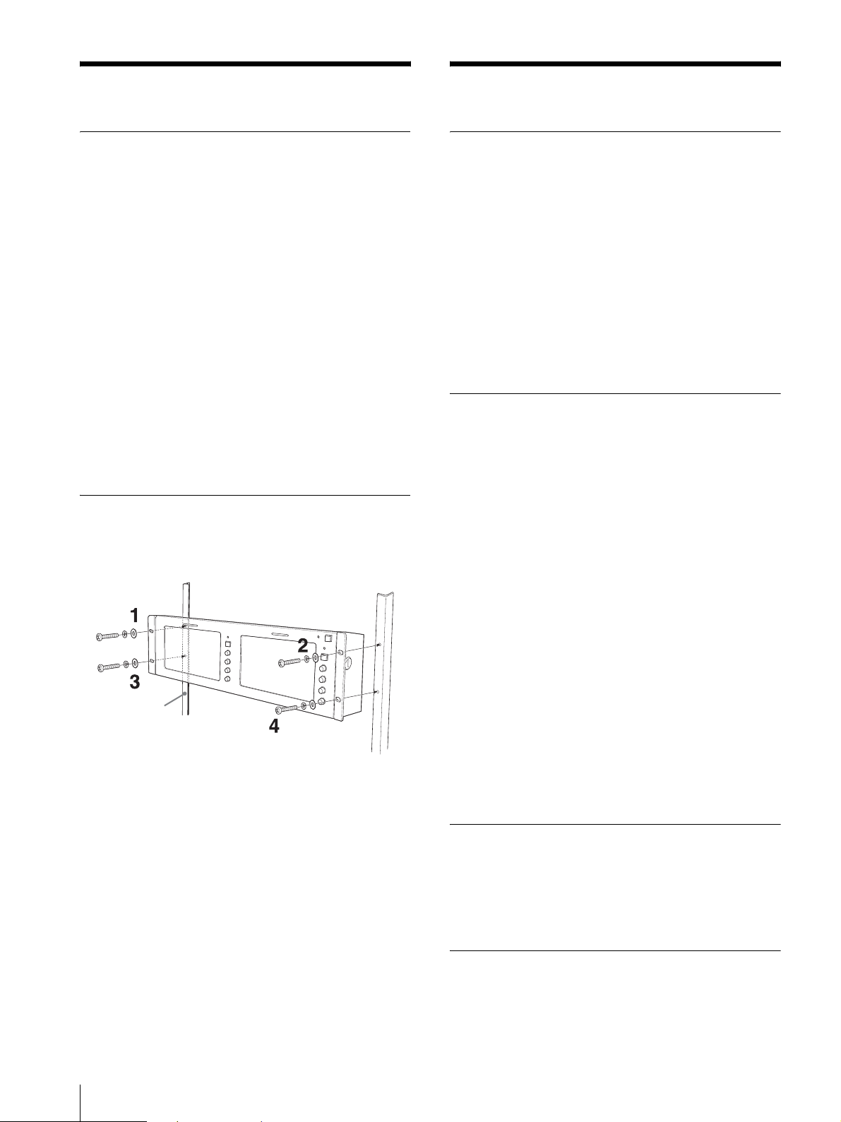
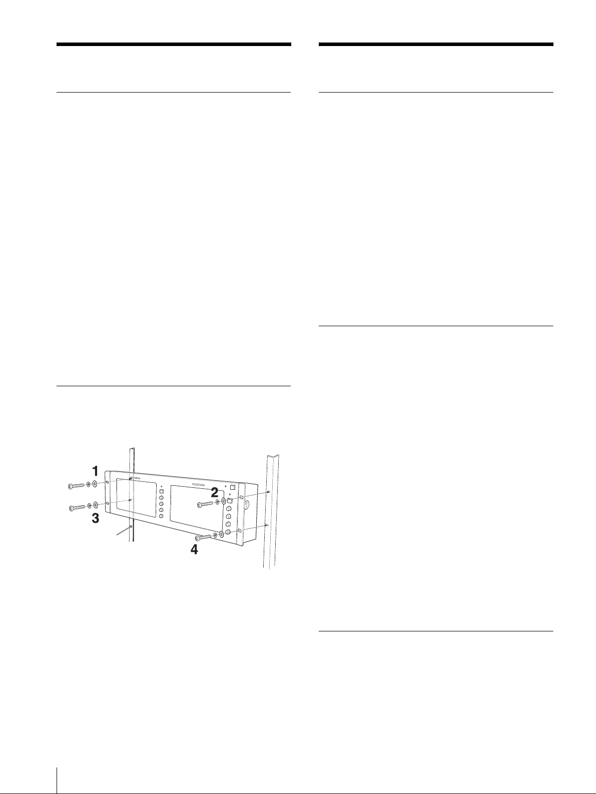
ラックに取り付けるには
ブラケット固定用のネジは図のように、先に上側のネジ
を取り付けてから下側のネジを取り付けてください。
使用上のご注意
液晶画面について
・ 液晶画面を太陽にむけたままにすると、液晶画面を痛め
てしまいます。窓際や室外に置くときなどはご注意くだ
さい。
・ 液晶画面を強く押したり、ひっかいたり、上にものを置
いたりしないでください。画面にムラが出たり、液晶パ
ネルの故障の原因になります。
・ 寒い所でご使用になると、横縞が見えたり、画像が尾を
引いて見えたり、画面が暗く見えたりすることがありま
すが、故障ではありません。温度が上がると元に戻りま
す。
・ 静止画を継続的に表示した場合、残像を生じることがあ
りますが、時間の経過とともに元に戻ります。
・ 使用中に画面やキャビネットがあたたかくなることがあ
りますが、故障ではありません。
輝点・滅点について
画面上に常時点灯している輝点(赤、青、緑など)や滅
点がある場合があります。
液晶パネルは非常に精密な技術で作られており、99.99
%以上の有効画素がありますが、ごくわずかの画素欠け
や常時点灯する画素があります。
お手入れのしかた
・ お手入れをする前に、必ず電源プラグをコンセントから
抜いてください。
・ モニターの画面は特殊加工がされていますので、なるべ
く画面にふれないようにしてください。また画面の汚れ
本機は動作温度条件 0 ℃〜 35 ℃を想定して設
計されています。
設置にあたってはこの温度を超えないことをお
確かめください。
本機をラックやモニター棚に収納した際に、動
作温度条件を超える場合は、セットの上、下お
よび周辺機器との隙間を充分にあけ、条件内に
おさまるように配慮してください。
密封されるようなラックまたはコンソールにマ
ウントする場合は、ファンによる強制冷却が必
要になる場合があります。
ラック

主な特長
7
JP
を拭きとるときは、乾いた柔らかい布で拭き取ってくだ
さい。
・ シンナー、ベンジンなどは使わないでください。変質す
ることがあります。
・ 化学ぞうきんをご使用の際は、その注意書きに従ってく
ださい。
・ 殺虫剤のような揮発性のものをかけたり、ゴムやビニー
ル製品に長時間接触させると、変質することがありま
す。
電源接続について
付属の AC アダプターをお使いください。
廃棄するときは
・ 一般の廃棄物と一緒にしないでください。
ごみ廃棄場で処分されるごみの中にモニターを捨てない
でください。
・ 本機の蛍光管の中には水銀が含まれています。破棄の際
は、地方自治体の条例または規則に従ってください。
主な特長
LCD モニター LMD‑720W は EIA19 インチラックに搭
載できる 7 型ワイド 2 連モニター、LMD‑530 は 5.6 型
3 連モニター、LMD‑440 は 4 型 4 連モニターです。
高輝度 LCD パネル
高輝度、高コントラストな LCD パネルの採用により、
様々な照明環境で鮮明に映像を再現できます。
チルト機構付ラックマウント機能
LMD‑720W、LMD‑530 は 3U サイズ、LMD‑440 は
2U サイズと EIA19 インチラックマウントに標準で搭載
でき、チルト機構が付いています。放送中継車など限ら
れた設置環境に、より多くの機器を搭載可能にした省ス
ペース設計です。
操作性、デザイン性を重視した操作部縦型
配列
操作部を縦型に配列し、下方向にチルトしたときの操作
性が損なわれません。
軽量薄型と AC パワーアダプター搭載機能
軽量薄型設計のため放送中継車への重量負荷が軽減され、
より広い作業空間が得られます。また、AC パワーアダプ
ターをモニター背面に搭載できるなど、実際のシステム
運用に細かく配慮した設計を施しています。
2 カラー方式に対応
NTSC、PAL の 2 カラー方式に対応しており、切り換え
は自動です。
SDI オプション入力機能
別売りのインプットアダプター (BKM‑320D) を取り付け
ると SDI 信号も入力することができます。アダプターは
各画面ごとに接続できます。
省電力設計
LMD‑720W は約 22W、LMD‑530 は約 22W、LMD‑
440 は約 18W と消費電力が少なく、車載などの際も発
電容量を抑えることができます。
外部リモート機能
オプション入力(BKM‑320D 取り付け時)とビデオ入力
の切り換え、タリーランプ、アスペクト(LMD‑720W
のみ)を外部機器を使って操作できます。
3 色タリーランプ
赤、緑、アンバーと 3 色表示できるタリーランプを搭載。
放送中かどうかなど各入力画像のモニタリング状態を瞬
時に把握できます。
アスペクト切り換え機能(LMD‑720W の
み)
ビデオ信号入力時に応じて 16:9 と 4:3 の画角を切り
換えることが可能です。
各部の名称と働き
JP
8
各部の名称と働き
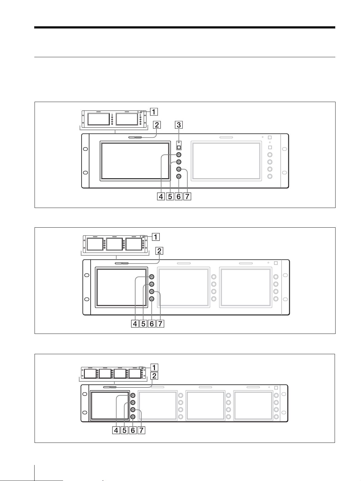
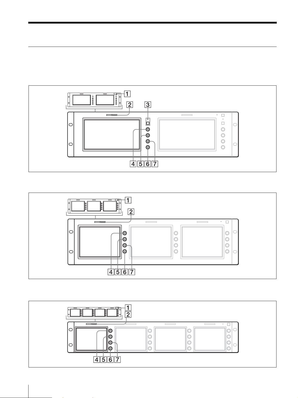
前面
POWER スイッチとインジケーター以外は各画面ごとに付いています。
LMD‑720W
LMD‑530
LMD‑440

各部の名称と働き
9
JP
A POWER(電源)スイッチとインジケーター
押すたびにモニターの電源を入/切します。電源が入る
とインジケーターが緑色に点灯します。
B タリーランプ
入力画面のモニター状態を色によって管理することがで
きます。
本機の REMOTE 端子に接続されている機器から赤 , 緑
のランプを点灯させることができ、赤と緑を同時に点灯
するとアンバーになります。
タリーランプを点灯させるには、タリー制御の配線が必
要です。
詳しくは 10 ページをご覧ください。
C アスペクトボタンとインジケーター(LMD‑720W
のみ)
画面のアスペクト(縦横比)を選びます。
このボタンを押すと画面のアスペクトが 4:3 に切り換
わり、インジケーターが点灯します。
D CONTRAST(コントラスト)調整つまみ
右に回すとコントラストが強くなり、左に回すと弱くな
ります。
E PHASE(色相)調整つまみ
この調整つまみは、NTSC カラ−方式の信号にだけ働
きます。
右へ回すと、肌色が緑がかります。
左へ回すと、肌色が紫がかります。
F BRIGHT(明るさ)調整つまみ
右へ回すと、画面が明るくなります。
左へ回すと、画面が暗くなります。
モニターの視野角を決めて画像が見にくい場合、明るさ
を調節すると画像が補正されて見やすくなる場合があり
ます。
G CHROMA(色の濃さ)調整つまみ
右へ回すと、色が濃くなります。
左へ回すと、色が薄くなります。
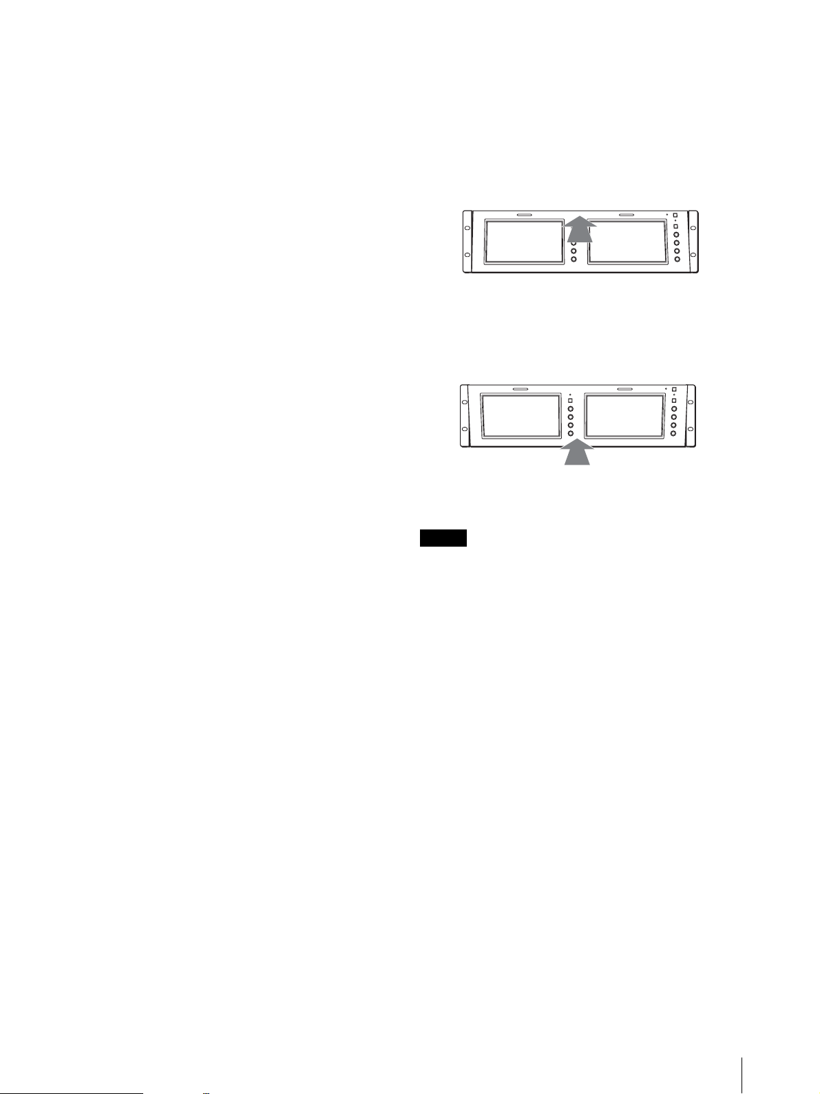
モニターの角度を調整するには
モニターは上または下に 10 度まで傾けてお使いいただけ
ます。
上に向けたいとき
下に向けたいとき
ご注意
アダプターを取り付けた状態でモニターを傾け、上下に
設置した機器とぶつかる場合は、AC アダプターホルダー
を取りはずしてください。
上部のまん中を押す。
下部のまん中を押す。
各部の名称と働き
JP
10
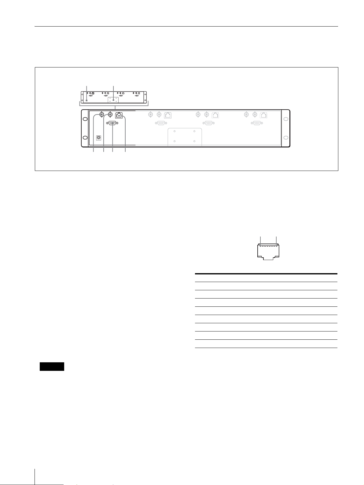
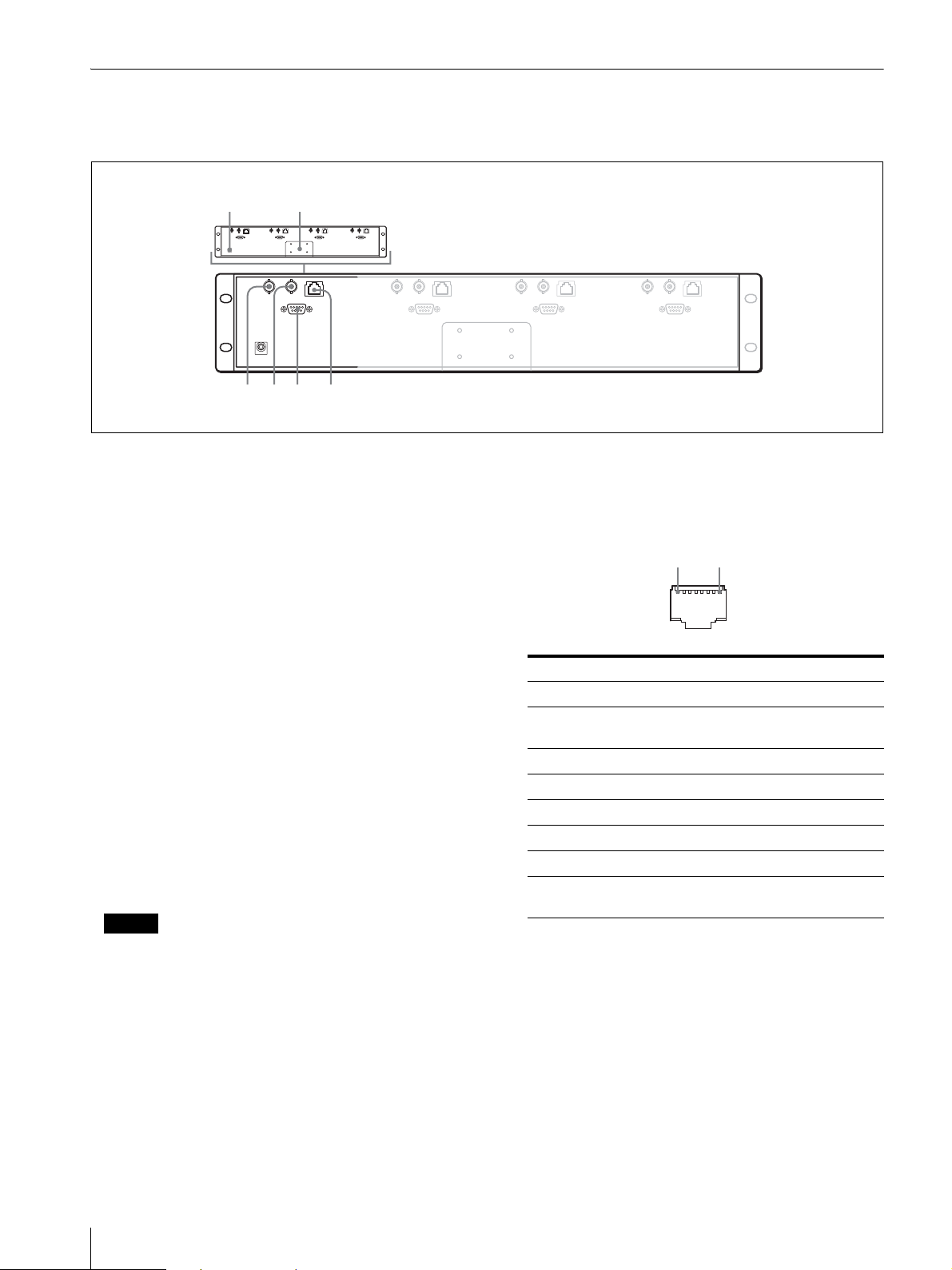
裏面
図は LMD‑440 です。
DCIN ジャックと AC アダプター取り付け部以外は各画面ごとに端子が付いています。
A DCIN ジャック
付属の AC アダプターを接続します。
B AC アダプタ−取り付け部
付属の AC アダプターを取り付けます。
C VIDEOIN(映像入力)端子(BNC 型)
ビデオデッキなどの映像出力端子と接続します。
OPTIONIN 端子にインプットアダプター BKM‑320D
を取り付けると、この端子は働かなくなります。
REMOTE 端子を使うとオプション入力(OPTION)
とビデオ入力(VIDEO)を切り換えることができます。
D VIDEOOUT(映像出力)端子(BNC 型)
VIDEOIN 端子に入力されている映像をル−プスル−
出力します。
75Ω に自動的に終端されます。
E OPTIONIN(インプットアダプタ−入力)端子(D‑
sub9 ピン、メス)
別売りのソニーインプットアダプター BKM‑320D を
取り付けると SDI 信号を入力できます。
ご注意
BKM‑320D 以外の機器を取り付けないでください。取
り付けると故障の原因になります。
F REMOTE(リモート)端子(モジュラーコネク
ター)
パラレルコントロールスイッチを構成してモニターを外
部操作します。
ピン配列と機能の割り付けは以下のとおりです。
*BKM‑320D 装着時に機能する。両方のピンをショート
させているときは OPTIONIN(SDI) が VIDEOIN に優
先します。
**LMD‑720W のみ
LMD‑530/440:未接続
以下のようにピンの設定を変えて、各機能を切り換えま
す。
High:各ピンをオープンにする。
Low:各ピンと 5 ピンをショートさせる。
12
345 6
ピン番号 機能 (HighyLow)
1 VIDEOIN (OFFyON)*
2 OPTIONIN (OFFyON)*
3タリー赤(OFFyON)
4タリー緑(OFFyON)
5接地
6未接続
7未接続
8 16:9/4:3 切換 (16:9y 4:3)**
1 8
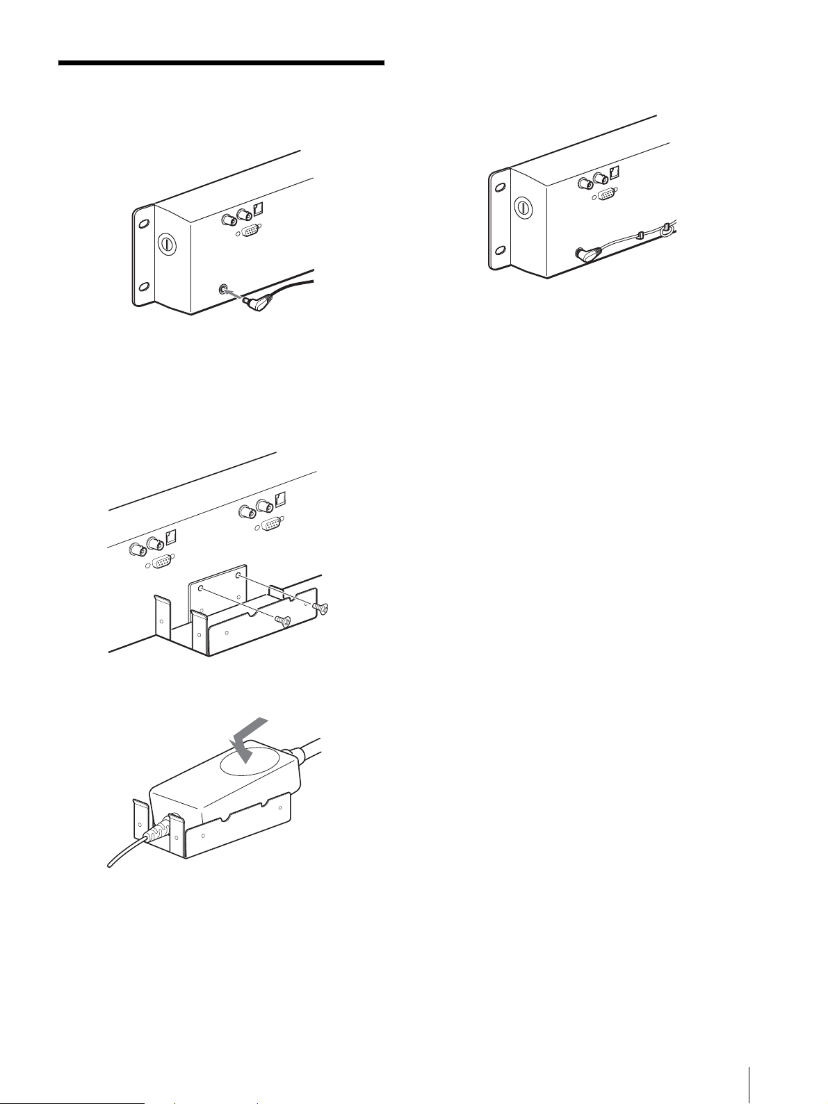
電源について
11
JP
電源について
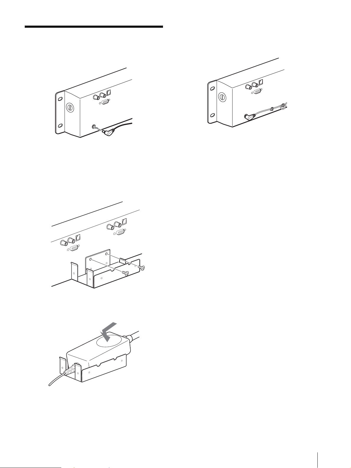
AC アダプターを接続します。
AC アダプターをモニターに取り付けると
き
1
付属の取り付け金具をモニター裏面に取り付ける。
2
AC アダプターを取り付ける。
AC アダプターのコードについて
次のようにまとめてください。

保証書とアフターサービス/主な仕様
JP
12
保証書とアフターサービ
ス
保証書
・ この製品には保証書が添付されていますので、お買い上
げの際お受け取りください。
・ 所定事項の記載内容をお確かめのうえ、大切に保存して
ください。
アフターサービス
調子が悪いときはまずチェックを
この説明書をもう一度ご覧になってお調べください。
それでも具合の悪いときはサービスへ
お買い上げ店、または添付の「ソニー業務用製品ご相談
窓口のご案内」にあるソニーサービス窓口にご相談くだ
さい。
保証期間中の修理は
保証書の記載内容に基づいて修理させていただきます。
詳しくは保証書をご覧ください。
保証期間経過後の修理は
修理によって機能が維持できる場合は、ご要望により有
料修理をさせていただきます。
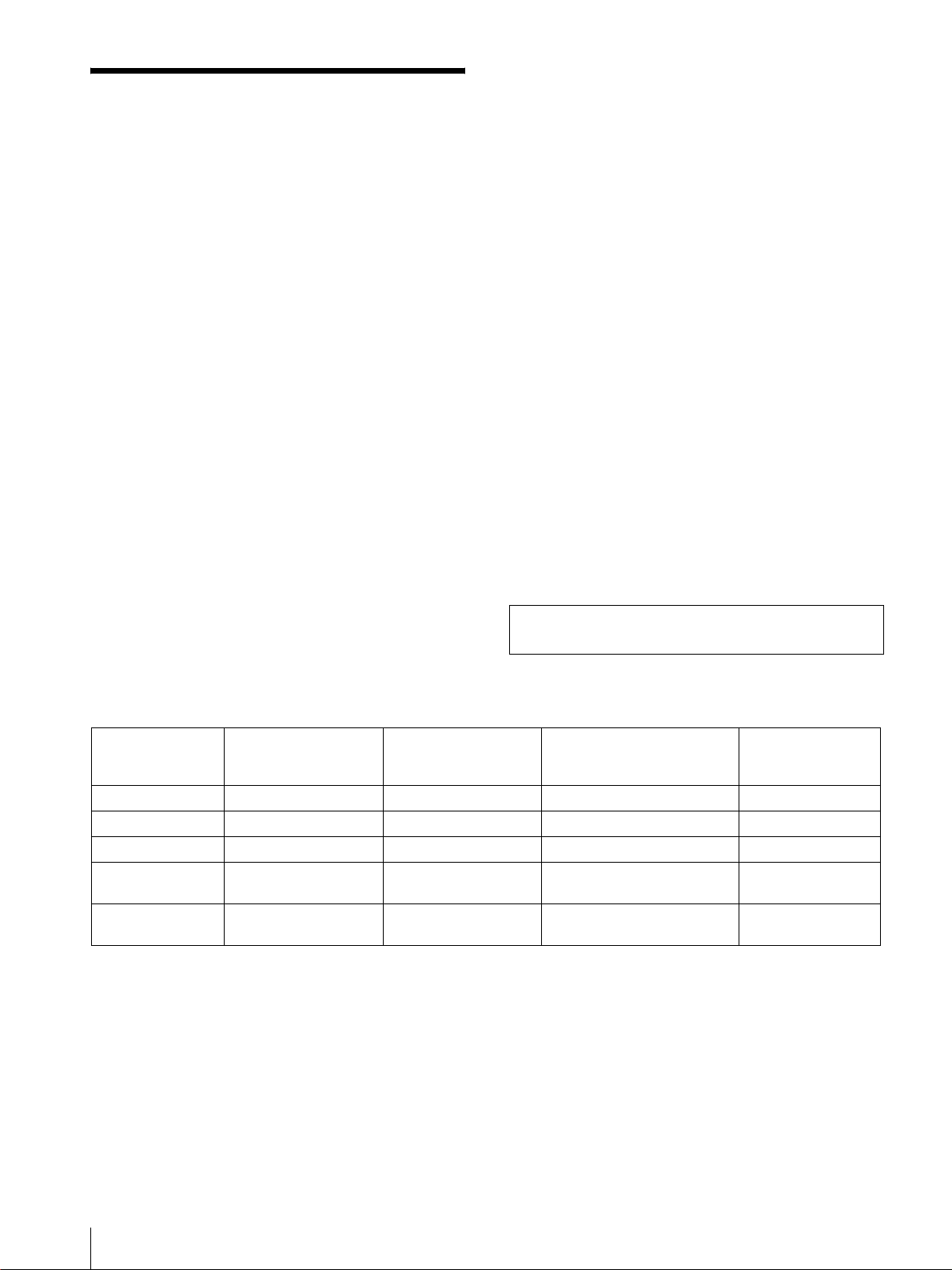
主な仕様
画像系
LMD‑720W
LCD パネル a‑SiTFT アクティブマトリックス
画面サイズ 7 型
154 × 87 × 177.8mm
(幅×高さ×対角)
解像度 480 × 234ドット
有効画素率 99.99%
視野角 30°/60°/60°/60° (typical)
(上 / 下 / 左 / 右コントラスト 10:1)
アスペクト 16:9
表示色 フルカラー
LMD‑530
LCD パネル a‑SiTFT アクティブマトリックス
画面サイズ 5.6 型
113 × 85 × 142.24mm
(幅×高さ×対角)
解像度 320 × 234 ドット
有効画素率 99.99%
視野角 30°/10°/45°/45° (typical)
(上 / 下 / 左 / 右コントラスト 10:1)
アスペクト 4:3
表示色 フルカラー
LMD‑440
LCD パネル a‑SiTFT アクティブマトリックス
画面サイズ 4 型
82.1 × 61.8 × 101mm
(幅×高さ×対角)
解像度 480 × 234ドット
有効画素率 99.99%
視野角 30°/10°/45°/45° (typical)
(上 / 下 / 左 / 右コントラスト 10:1)
アスペクト 4:3
表示色 フルカラー
入/出力
LMD‑720W
VIDEO IN:BNC 型× 2、コンポジット 1V
P‑P
± 2dB、同期負(75Ω 終端)
OUT:ループスルー BNC 型× 2、
VIDEOIN 端子のル−プスル−出力
(75Ω 自動終端)

主な仕様
13
JP
OPTIONIN 端子
D‑sub9 ピン× 2
REMOTE 端子 モジュラーコネクター 8 ピン× 2(ピン
配列については 10 ページ参照)
LMD‑530
VIDEO IN:BNC 型× 3、コンポジット 1V
P‑P
± 2dB、同期負(75Ω 終端)
OUT:ループスルー BNC 型× 3、
VIDEOIN 端子のル−プスル−出力
(75Ω 自動終端)
OPTIONIN 端子
D‑sub9 ピン× 3
REMOTE 端子 モジュラーコネクター 8 ピン× 3(ピン
配列については 10 ページ参照)
LMD‑440
VIDEO IN:BNC 型× 4、コンポジット 1V
P‑P
± 2dB、同期負(75Ω 終端)
OUT:ループスルー BNC 型× 4、
VIDEOIN 端子のル−プスル−出力
(75Ω 自動終端)
OPTIONIN 端子
D‑sub9 ピン× 4
REMOTE 端子 モジュラーコネクター 8 ピン× 4(ピン
配列については 10 ページ参照)
一般
消費電力 LMD‑720W
最大:約 26W(BKM‑320Dを 2 個取
り付け)
標準:約 22W(入力アダプター取り付
け無し)
LMD‑530
最大:約 28W(BKM‑320Dを 3 個取
り付け)
標準:約 22W(入力アダプター取り付
け無し)
LMD‑440
最大:約 26W(BKM‑320D を 4 個取
り付け)
標準:約 18W(入力アダプター取り付
け無し)
電源 DC12V(付属の AC アダプター使用)
動作条件 温度 0
〜+35℃
湿度 30 〜 85%(結露のないこと)
気圧 700
〜 1,060hPa
保存/輸送条件 温度
−10 〜+40℃
湿度 0 〜 90%
気圧 700
〜 1,060hPa
最大外形寸法 LMD‑720W:約483 × 131 × 47
mm(幅×高さ×奥行き)
LMD‑530:約483 × 131 × 47mm
(幅×高さ×奥行き)
LMD‑440:約483 × 88.1 × 47mm
(幅×高さ×奥行き)
質量 LMD‑720W:約2.3kg
LMD‑530:約2.3kg
LMD‑440:約1.9kg
付属品 AC アダプター(1)
AC アダプターホルダー (1)
アダプター取り付けねじ (2)
AC コード
保証書(1)
取扱説明書(1)
ソニー業務用製品ご相談窓口のご案内
(1)
別売りアクセサリー
インプットアダプター BKM‑320D
本機の仕様および外観は、改良のため予告なく変更する
ことがありますが、ご了承ください。
電源接続時のご注意
それぞれの地域に合った電源コードをお使いください。
1)プラグに関しては各国規制に適合し、使用に適した定格のものを使用してください。
アメリカ合衆国、カナダ ヨーロッパ諸国 イギリス、アイルランド、
オーストラリア、ニュージーランド
日本
プラグ型名 VM0233 COX‑07/636
1)
YP332
コネクタ型名 VM0089 COX‑02/VM0310B VM0303B YC‑13
コード型名 SVT H05VV‑F CEE(13)53rd(O.C) VCTF
定格電圧・電流 10A/125V 10A/250V 10A/250V 7A/125V
安全規格 UL/CSA VDE VDE 電安
GB
2
WARNING
Owner's Record
The model and serial numbers are located at the rear.
Record these number in the space provided below.
Refer to these numbers whenever you call upon your
Sony dealer regarding this product.
Model No. ____________________
Serial No. ____________________
T o prevent f ire or shock hazard, do not expose the unit to
rain or moisture.
Dangerously high voltages are present inside the unit.
Do not open the cabinet. Refer servicing to qualified
personnel only.
In the event of a malfunction or when maintenance is
necessary, consult an authorized Sony dealer.
This unit contains substances which can pollute the
environment if disposed carelessly. Please contact our
nearest representative off ice or your local environmental
office in case of disposal of this unit.
Power S wit ch
The power switch is a functional switch only.
To isolate the set from the mains supply remove the
mains plug from the wall socket.
CAUTION
Danger of explosion if battery is incorrectly replaced.
Replace only with the same or equivalent type
recommended by the manufacturer.
Dispose of used batteries according to the
manufacturer’s instructions.
For customers in Canada
This Class A digital apparatus complies with Canadian
ICES-003.
For the customers in Europe
This product with the CE marking complies with the
EMC Directive (89/336/EEC) issued by the
Commission of the European Community.
Compliance with this directive implies conformity to the
following European standards:
• EN55103-1: Electromagnetic Interference (Emission)
• EN55103-2: Electromagnetic Susceptibility
(Immunity)
This product is intended for use in the following
Electromagnetic Environment(s):
E1 (residential), E2 (commercial and light industrial),
E3 (urban outdoors) and E4 (controlled EMC
environment, ex. TV studio).
For the Customers in the USA
This equipment has been tested and found to comply
with the limits for a Class A digital device, pursuant to
Part 15 of the FCC Rules. These limits are designed to
provide reasonable protection against harmful
interference when the equipment is operated in a
commercial environment. This equipment generates,
uses, and can radiate radio frequency energy and, if not
installed and used in accordance with the instruction
manual, may cause harmful interference to radio
communications. Operation of this equipment in a
residential area is likely to cause harmful interference in
which case the user will be required to correct the
interference at his own expense.
This device complies with Part 15 of the FCC Rules.
Operation is subject to the following two conditions: (1)
This device may not cause harmful interference, and (2)
this device must accept any interference received,
including interference that may cause undesired
operation.
Y o u are cautioned that any changes o r modificati ons not
expressly approved in this manual could void your
authority to operate this equipment.
This product contains mercury. Disposal of this product
may be regulated if sold in the United States. For
disposal or recycling information, please contact your
local authorities or the Electronics Industries Alliance
(www.eiae.org http://www.eiae.org).
Be sure to connect the AC power cord to a grounded
outlet.
Warning on power connection
Use a proper power cord for your local power supply
1) Use an appropriate rating plug which is applied to local regulations.
The United States,
Canada
Continental Europe UK, Ireland, Australia,
New Zealand
Japan
Plug type VM0233 COX-07/636
_ 1)
YP332
Female end VM0089 COX-02/VM0310B VM0303B YC-13
Cord type SVT H05VV-F CEE(13)53rd (O, C) VCTF
Rated Voltage &
Current
10A/125V 10A/250V 10A/250V 7A/125V
Safety approval UL/CSA VDE VDE DENAN
GB
3
GB
Table of Contents
Installation ..............................................................4
Cautions ..............................................................4
Installing to the rack ...........................................4
Precautions .............................................................4
On safety .............................................................4
Handling the LCD screen ...................................4
About the fluorescent tube ..................................4
Maintenance ........................................................4
Disposal of the unit .............................................5
Features ...................................................................5
Location and Function of Parts and Controls .....6
Front Panel ..........................................................6
Rear .....................................................................8
Power Sources .......... ...............................................9
Specifications ........................................................10
About this manual
The instructions in this man ual are for the following
three models:
• LMD-440 (4 type)
• LMD-530 (5.6 type)
• LMD-720W (7 type)
Any differences in operation are clearly indicated in
the text.
Installation / Precautio ns
GB
4
Installation
Cautions
• Prevent internal heat build-up allowing adequate air
circulation.
Do not place the unit on surfaces (rugs, bl ankets, etc.)
or near materials (curtains, draperies) that may block
the ventilation holes.
• Do not install the unit near heat sources such as
radiators or air ducts, or in a place subject to direct
sunlight, excessive dust, mechanical vibration or
shock.
• Do not place the monitor near equipment which
generates magnetism, such as a transformer or high
voltage power lines.
• Use the unit unde r an operati ng temperature of 0°C to
35°C (32°F to 95°F).
• When the unit is installed on the rack or on a shelf,
leave the space above and beneath the unit and
between the unit and other equipment.
• Use a fan to cool the unit if the spaces are small.
Installing to the rack
First secure the upper screws and then the lo wer ones, as
illustrated below.
Precautions
On safety
• Operate the unit on 100 - 240 V AC only.
• The nameplate indicating operating voltage, power
consumption, etc. is located on the rear.
• Should an y sol id obj ect or li qu id fall into the cabinet ,
unplug the unit and have it checked by qualified
personnel before operating it any further.
• Unplug the unit from the wal l outlet if it is not to be
used for several days or more.
• To disconnect the AC power cord, pull it out by
grasping the plug. Never pull the cord itself.
• The socket-outlet shal l be installed near the equipment
and shall be easily accessible.
Handling the LCD screen
• Bright or dark points of lights (r ed, blue or green) may
appear on the LCD screen. This is not a malfunction.
The LCD screen is made with high-precision
technology and more than 99.99 % of the picture
element is intact. However, some of the picture
element may not appear or some of the p icture element
may appear constantly.
• Do not leave the LCD screen facing the sun as it can
damage the LCD screen. Take care when you place
the unit by a window.
• Do not push or scratch the LCD monitor’s screen. Do
not place a heavy object on the LCD monit or’ s screen.
This may cause the screen to lose uniformity.
• If the unit is used in a cold place, the horizontal lines
or a residual image may appear on the screen. T his is
not a malfunction. When the monitor becomes warm,
the screen returns to normal.
• If a still pic ture is di splayed for a long t ime, a residual
image may appear . The residual i mage will ev entually
disappear.
• The screen and the cabinet become warm during
operation. This is not a malfunction.
About the fluorescent tube
A specially designed fluorescent tube is installed as the
lighting apparatus for this unit. If the LCD screen
becomes dark, unstable or does not turn on, consult your
Sony dealer.
Maintenance
• Clean the cabinet, panel and controls with a soft cloth
lightly moistened with a mild detergent solution. Do
Rack

Features
5
GB
not use any type of abrasive pad, scouring powder or
solvent, such as benzine.
• Do not rub, touch, or tap the surface of th e screen with
sharp or abrasive items such as a ball-point pen or
screwdriver. This type of contact may result in a
scratched picture panel.
• Clean the screen with a soft cloth. If you use a glass
cleaning liquid, do not use any type of cleaner
containing an antistatic solution or similar additive as
this may scratch the screen’s coating.
Disposal of the unit
• Do not dispose of the unit wit h general w aste. Do not
include the monitor with household waste.
• The fluorescent tube includes mercury . Disp ose of the
monitor in accordance with the regulations of your
local sanitation a uthority.
If you have any questions about this unit, contact your
authorized Sony dealer.
Features
Two 7-type wide LCD panels are mounted for LMD-
720W, three 5.6-type LCD panels are mounted for
LMD-530 and four 4-type LCD panels are mounted fo r
LMD-440.
High brightness LCD panel
Because the monitor uses high brightness and high
contrast technology, it can be used under various
lighting conditions.
Rack mount monitors with tilt function
LMD-720W and LMD-530 are mounted to a 3U size
rack and LMD-440 is mounted to a 2U size rack. All the
monitors are equipped with tilt function. They can be
installed to a 19-inch standard rack. They are essential
when space is at a premium in crowded OB vehicles.
Vertical arrangement of controls for easy
operation and unitary layout
The controls of thre e models are laid out vertica lly and
have a unitary design. When the monitor is tilted
downward, it is easy to operate.
Lightweight, thin design/AC power
adaptor mount function
The lightweight, thi n design redu ces the load f or an OB
vehicle and the space needed for the equipment. Also,
an AC power adaptor can be installed to the rear of the
monitor for easy use.
Two color system available
The monitor can display NTSC and PAL signals. The
appropriate color system is selected automatically.
SDI optional input function
SDI signals can be available when input adaptor BKM-
320D (optional) is attached. The adaptor can be
attached to each monitor.
Energy-saving design
Because of the low power consumption LMD-720W
22W, LMD-530 22W and LMD-440 18W electric
power, the generation in an OB vehicle is reduced.
Remote function
The switching of a n optional inp ut (when BKM-32 0D is
connected) and video input, tally lamp and aspect ratio
(LMD-720W only) can be controlled by an external
equipment.
3-color tally lamp
The tally lamp lights in red, green or amber to monitor
each input picture and check the on-air mode. The tally
function can be operated with the remote function.
Aspect setting (LMD-720W only)
You can set the monitor to 16:9 or 4:3 when a video
signal is input.
Location and Function of Parts and Controls
GB
6
Location and Function of Parts and Controls
Front Panel
Each panel is equipped with buttons and controls other than the POWER switch and indicator.
LMD-720W
LMD-530
LMD-440
Location and Function of Parts and Controls
7
GB
A POWE R swit ch and in di cat or
Each time you press the switch, the power is turned on
or off. When the power is turned on, the indicator
lights in green.
B Tally lamp
Y o u can check the status of the monitor that the signal
is input by the color.
The lamp lights in red or green by signals from the
equipment connected to the REMOTE connector.
When red and green signals ar e input, the lamp lights
in amber.
The pins on the REMOTE connector are used to
control the tally lamp.
For details, see page 8.
C Aspect select button and indi cator (LMD-720W
only)
Sets the aspect ratio of the picture. When the button is
pressed, the aspect ratio of the picture is set to 4
:3 and
the indicator lights.
D CONTRAST control
Turn this control clockwise to make the co ntrast
higher or counterclockwise to make it lower.
E PHASE control
This control is effective only for the NTSC color
system.
Turn it clockwise to make the skin tones greenish or
counterclockwise to make them purplish.
F BRIGHT (brightness) control
Turn this con trol cl ock w ise to increase t he b rig htness
or counterclockwise to decrease it.
Indistinctness of the pictur e when the viewing angle of
the monitor is adjusted may be compensated by
adjusting the brightness.
G CHROMA control
Turn this control clockwise to increase the c olor
intensity or counte rc lockwise to decrease it.
Adjusting the viewing angle
Y ou can adjust the vie wing angle of the monitor up t o 10
degrees upward or downward.
Adjusting upward
Adjusting downward
NOTE
When the AC adaptor is at tache d to the monitor and the
angle is adjusted, the AC adapto r may be touched to the
equipment set to upper or lower. Remove the AC
adaptor holder from the monitor.
Press the center top.
Press the center bottom.
Location and Function of Parts and Controls
GB
8
Rear
The illustration refers to LMD-440.
Each panel is equipped with connectors other than the DC IN jack and AC adaptor attachment.
A DC IN jack
Connect the supplied AC adaptor.
B AC adaptor attachment
Attach the supplied AC adaptor.
C VIDEO IN connector (BNC)
Connect to the video output connector of the VCR,
etc.
When input adaptor BKM-320D is connected to the
OPTION IN connector, this connector does not
function.
An optional input (OPTION) and video input
(VIDEO) can be switched by using the REMOTE
connector.
D VIDEO OUT connector (BNC)
Loop-through output of the VIDEO IN connector.
The connector is automatically terminat ed at 75 ohms.
E OPTION IN connector (D-sub 9 pin, female)
When optional Sony input adaptor BKM-320D is
connected, SDI signals are input.
NOTE
Do not install the other equipment t han BKM-3 20D.
It causes to damage the unit or the equipment.
F REMOTE connector (modular)
Forms a parallel switch and controls the monitor
externally. The pin assignment and factory setting
function assigned to each pin are given below.
*Functions when BKM-320D is connected. When
both pins are shorted, OPTION IN (SDI) is prior to
VIDEO IN.
**LMD-720W only
LMD-530/440: N.C
T o switch each function between high and lo w , change
pin connections in the following way.
High: Leave each pin open.
Low: Short each pin and 5-pin at the same time.
12
345 6
Pin number Function (High y Low)
1 VIDEO IN (OFF y ON)*
2 OPTION IN
(SDI)
(OFF y ON)*
3 Tally Red (OFF y ON)
4 Tally Green (OFF y ON)
5Ground
6N.C
7N.C
8 16:9/4:3
Selectable
(16:9 y 4:3)**
1 8
Power Sources
9
GB
Power Sources
Connect the AC adaptor.
When attaching the AC adaptor to the
monitor
1
Install the supplied bracket to the rear of the
monitor.
2
Attach the AC adaptor.
About the AC adapto r cord
Clamp the cord as illustrated.

Specifications
GB
10
Specifications
Picture performance
LMD-720W
LCD Panel a-Si TFT Active Matrix
Picture size 7 type
154
× 87 × 177.8 mm (W/H/
Diagonal)
(6
× 3
3
/7 × 7 inches)
Resolution 480
× 234 dots
Pixel efficiency 99.99 %
Viewing angle 30°/60°/60°/60° (typical)
(up/down/left/right contrast 10:1)
Aspect ratio 16:9
Colors Full color
LMD-530
LCD Panel a-Si TFT Active Matrix
Picture size 5.6 type
113
× 85 × 142.24 mm (W/H/
Diagonal)
(4
4
/9 × 3
1
/3 × 5
3
/5 inches)
Resolution 320
× 234 dots
Pixel efficiency 99.99 %
Viewing angle 30°/10°/45°/45° (typical)
(up/down/left/right contrast 10:1)
Aspect ratio 4:3
Colors Full color
LMD-440
LCD Panel a-Si TFT Active Matrix
Picture size 4 type
82.1
× 61.8 × 101 mm (W/H/
Diagonal)
(3
1
/4 × 2
3
/7 × 4 inches)
Resolution 480
× 234 dots
Pixel efficiency 99.99 %
Viewing angle 30°/10°/45°/45° (typical)
(up/down/left/right contrast 10:1)
Aspect ratio 4:3
Colors Full color
Input/output
LMD-720W
VIDEO IN: BNC connectors (2), composite 1
Vp-p
± 2 dB, sync negative (75
ohms terminated)
OUT: BNC connectors (2), loop-
through (75 ohms terminated
automatically)
OPTION IN
D-sub 9-pin connectors (2)
REMOTE Modular connectors 8-pin (2) (See the
pin assignment on page 8.)
LMD-530
VIDEO IN: BNC connectors (3), composite 1
Vp-p
± 2 dB, sync negative (75
ohms terminated)
OUT: BNC connectors (3), loop-
through (75 ohms terminated
automatically)
OPTION IN
D-sub 9-pin connectors (3)
REMOTE Modular connectors 8-pin (3) (See the
See the pin assignment on page 8
LMD-440
VIDEO IN: BNC connectors (4), composite 1
Vp-p
± 2 dB, sync negative (75
ohms terminated)
OUT: BNC connectors (4), loop-
through (75 ohms terminated
automatically)
OPTION IN
D-sub 9-pin connectors (4)
REMOTE Modular connectors 8-pin (4) (See the
pin assignment on page 8.)
General
Power consumption
LMD-720W
Maximum: Approx. 26W (with
2
×B KM-320D)
Standard: Approx. 22W (without
optional input adaptor)
LMD-530
Maximum: Approx. 28W (with
3
×B KM-320D)
Standard: Approx. 22W (without
optional input adaptor)
LMD-440
Maximum: Approx. 26W (with
4
×B KM-320D)
Standard: Approx. 18W (without
optional input adaptor)
Power requirement
12 V DC (with the supplied AC
adaptor)
When this product is operated by AC adaptor:

Specifications
11
GB
Peak inrush current
LMD-720W
(1) Power ON, current probe method: 57 A (230V)
(2) Hot switching inrush current, measured in
accordance with European standard EN55103-1:
8 A (230 V)
LMD-530
(1) Power ON, current probe method: 55 A (230V)
(2) Hot switching inrush current, measured in
accordance with European standard EN55103-1:
8 A (230 V)
LMD-440
(1) Power ON, current probe method: 53 A (230V)
(2) Hot switching inrush current, measured in
accordance with European standard EN55103-1:
8 A (230 V)
Operating conditions
Temperature: 0 to 35
°C (32 to 95°F)
Humidity: 30 to 85 % (No
condensation)
Pressure: 700 to 1,060 hPa
Transport and storage conditions
Temperature: –10 to 40
°C (14 to
104
°F)
Humidity: 0 to 90 %
Pressure: 700 to 1,060 hPa
Dimensions (w/h/d)
LMD-720W: Approx . 483
× 131 × 47
mm (19
× 5
1
/6 × 1
6
/7 inches)
LMD-530: Approx. 483
× 131 ×47
mm (19
× 5
1
/6 × 1
6
/7 inches)
LMD-440: Approx. 483
× 88.1 ×47
mm (19
× 3
1
/2 × 1
6
/7 inches)
Mass LMD-720W: Approx. 2.3 kg (5 l b 1 oz)
LMD-530: Approx. 2.3 kg (5 lb 1 oz)
LMD-440: Approx. 1.9 kg (4 lb 3 oz)
Accessories supplied
AC adaptor (1)
AC adaptor holder (1)
Screws for AC adaptor holder (2)
AC cord (1)
Warranty Card (1)
Operating Instructions (1)
Optional accessory
Input adaptor BKM-320D
Design and specificati ons are subj ect to change with out
notice
FR
2
AVERTISSEMENT
Afin d’éviter tout risque d’incendie ou d’électrocution,
ne pas exposer cet appareil à la pluie ou à l’humidité.
Des courants de hautes tensions dangereuses sont
présents à l’intérieur de cet appareil. Ne pas ouvrir le
coffret. Se reporter à un personal qualifié uniquement.
Dans le cas d’une défaillance ou de si un entretien est
nécessaire, consulter un revendeur Sony autorisé.
Cet appareil contient des substances susceptibles de
polluer l’environ nement si elles ne sont pas éliminées de
façon conforme. Consultez votre bureau local de
préservation de l’environnement pour savoir comment
vous débarrasser de cet appareil.
Interrupteur général
L’interrupteur général est un interrupteur de
fonctionnement uniquement.
Pour isoler le système de l’alimentation secteur, retirez
la fiche d’alimentation de la prise murale.
ATTENTION
Il y a un risque d’explosion en cas de remplacement
incorrent de la batterie.
Remplacer uniquement par une batterie de même type
ou de type équivalent recommandée par le constructeur.
Mettre les batteries usagées au reb ut conformémen t aux
instructions du fabricant.
Pour les utilisat eurs du Canada
Cet appareil numérique de la classe A est conforme à la
norme NMB-003 du Canada.
Pour les clients européens
Ce produit portant la marque CE est conforme à la
Directive sur la compatabilité élect romagnétique (EMC)
(89/336/CEE) émise par la Commission de la
Communauté européene.
La conformité à cette directive implique la conformité
aux normes européenes suivantes :
• EN55103-1 : Interférences électromagnétiques
(émission)
• EN55103-2 : Sensibilité électromagnétiq ue
(immunité)
Ce produit est prévu pour être utilisé dans les
environnements électromagnétiques suivants:
E1 (résidentiel), E2, (commercial et industrie légère),
E3 (urbain extérieur) et E4 (environnement EMC
contrôlé ex. studio de télévision).
Raccordez le cordon d’alimentat ion à une prise murale
mise à la terre.
Avertissement sur le raccordement de l’alimentation
Utilisez un cordon d’alimentation approprié à la tension secteur locale
1) Utilisez une prise correspondant à la réglementation en vigueur dans votre région.
États-Unis, Canada Europa
continentale
Royaume-Uni,
Irlande, Australie,
Nouvelle-Zélande
Japon
Type de fiche VM0233 COX-07/636
_ 1)
YP332
Extrémité femell e VM0089 COX-02/VM0310B VM0303B YC-13
Type de cordon SVT H05VV-F CEE(13)53rd (O, C) VCTF
Tension et courant
nominaux
10A/125V 10A/250V 10A/250V 7A/125V
Agréation de
sécurité
UL/CSA VDE VDE DENAN
3
FR
FR
Table de matières
Installation ..............................................................4
Précautions ..........................................................4
Installation sur le rack .........................................4
Précautions .............................................................4
Sécurité ...............................................................4
Manipulation de l’écran LCD .............................4
Tube fluorescent ..................................................4
Entretien ..............................................................5
Mise au rebut du moniteur ..................................5
Caractéristiques .....................................................5
Emplacement et fonction des composants et
commandes .............................................................7
Panneau avant .....................................................7
Arrière .................................................................9
Sources d’alimentation ........................................10
Spécifications ........................................................11
A propos de ce manuel
Les instructions contenue s dans ce manuel concernent
les 3 modèles suivants :
• LMD-440 (Type 4)
• LMD-530 (Type 5,6)
• LMD-720W (Type 7)
Toutes les différences de fonctionnement sont
indiquées clairement dans le texte.
Installation / Précautions
FR
4
Installation
Précautions
• Afin d’éviter toute surchauffe interne, assurez une
circulation d’air adéquate.
Ne placez pas l’appareil sur des surfaces textiles
(tapis, couvertures, etc.) ni à proximité de rideaux ou
de draperies susceptibles d’obstruer les orifices de
ventilation.
• N’installez pas l’appareil près d’une source de
chaleur, comme un radiateur ou une bouche d’air
chaud, ou dans un endroit exposé directement au
soleil, à de la poussière excessive, des vibrations ou
des chocs mécaniques.
• Ne placez pas le moniteur près d’un équipement
source de magnétisme tel qu’u n transformateur ou de s
lignes haute tension.
• Utilisez l’appareil à une température de
fonctionnement de 0 à 35°C (32 à 95°F).
• Lorsque l’appareil est monté sur le rack ou une
étagère, laissez un espace au-dessus et au-dessous de
l’appareil et entre l’appareil et un autre équipement.
• Utilisez un ventilateur pour refroidir l’appareil si les
dégagements sont réduits.
Installation sur le rack
Fixez d’abord les vis supérieu res, puis les vis inférieures
comme illustré ci-dessous.
Précautions
Sécurité
• Raccorder l’appareil à une prise secteur 100-240 V
uniquement.
• La plaquette signalétique indiquant la tension de
fonctionnement, la puissance consommée, etc., est
située à l’arrière de l’appareil.
• Si du liquide ou un obj et quelconque v enait à pénétrer
dans le châssis, débranchez l’appareil et faites-le
vérifier par un techni cien qualif i é a v ant de le remettre
en service.
• Débranchez l’appare il de la prise murale si vous
n’avez pas l’intention de l’utiliser pendant plusieurs
jours.
• Pour débrancher le cordon, saisissez-le par la fiche.
Ne jamais tirer sur le câble propre m ent dit.
• La prise secteur doit se trouver à proximité de
l’appareil et être facile d’accès.
Manipulation de l’écran LCD
• Des points lumineux ou sombres (rouges, bleus ou
verts) peuve nt appa raîtr e sur l’écran LCD. Il ne s’agit
pas d’une anomalie. L’écran LCD est conçu selon une
technologie de fabrication de haute précision et plus
de 99,99% des pixels sont intacts. Cependant, une
partie des pixels peut ne pas s’afficher ou s’afficher
constamment.
• Ne laissez pas l’écran LCD exposé au soleil. Faites
attention si vous le placez près d’une fenêtre.
• Ne poussez ou ne rayez pas l’écran LCD du moniteur.
Ne posez pas d’objets lourds sur l’écran. Il risquerait
de ne plus être uniforme.
• Si le moniteur est utilisé dan s un endroit frais, les
lignes horizontales ou une image résiduelle peuvent
apparaître sur l’écr an. Il ne s’agi t pas d’ une anomali e.
Lorsque le moniteur chauffe, l’écran redevient
normal.
• Si une image fixe est affichée pendant un certain
temps, une image résiduelle peut apparaître. Cette
image résiduelle dispara ît par la suite.
• L ’écran et le châssis chauffent pendant l’utilisation du
moniteur. Il ne s’agit pas d’une anomalie.
Tube fluorescent
Un tube fluorescent conçu spécialement est installé
comme dispositif lumineux d u moniteur . Si l’écran L CD
s’assombrit, devient instable ou ne s’allume pas,
consultez votre revendeur Sony.
Rack
 Loading...