


LDI-50BE (SYL)/ D50BE (SYL)
SERVICEMANUAL
PAL Model
LDI-50BE (SYL) /D50BE (SYL) LDI-50E (SYL) /D50E (SYL)LDI-50E (SYL) /D50E (SYL)LDI-50E (SYL) /D50E (SYL)9-928-125-2X
Model LDI-50BE (SYL) /D50BE (SYL) are almost the same as LDI-50E (SYL) /D50E (SYL). This manual contains only the points which differ from LDI-50E (SYL) /D50E (SYL).
For the information not contained in this manual, please refer to LDI-50E (SYL) /D50E (SYL) service manual (9-928-125-2X) previously issued.
Note: |
LDI-50BE (SYL) |
LDI-D50BE (SYL) |
|
RG-46P (E) Board |
RG-46P (F) Board |
|
SA-52P (E) Board |
SA-52P (F) Board |
|
SW-312 (E) Board |
SW-312 (F) Board |
|
YM-11P (E) Board |
YM-11P (F) Board |
|
|
|
LCD
PERSONAL LCD DISPLAY
9-928-131-21
項を表示しています。これらの注意書き及び取扱説明書 等の注意事項を必ずお守り下さい。
!
確保されていることを確認して下さい。
∙270
取扱いして下さい。フラットパッケージIC
Notes on chip component replacement
•Never reuse a disconnected chip component.
•Notice that the minus side of a tantalum capacitor may be damaged by heat.
Flexible Circuit Board Repairing
•Keep the temperature of the soldering iron around 270 ˚C during repairing.
•Do not touch the soldering iron on the same conductor of the circuit board (within 3 times).
•Be careful not to apply force on the conductor when soldering or unsoldering.
SAFETY-RELATED COMPONENT WARNING!!
COMPONENTS IDENTIFIED BY MARK ! OR DOTTED LINE WITH MARK ! ON THE SCHEMATIC DIAGRAMS
AND IN THE PARTS LIST ARE CRITICAL TO SAFE OPERATION. REPLACE THESE COMPONENTS WITH SONY PARTS WHOSE PART NUMBERS APPEAR AS SHOWN IN THIS MANUAL OR IN SUPPLEMENTS PUBLISHED BY SONY.
ATTENTION AU COMPOSANT AYANT RAPPORT
À LA SÉCURITÉ!
LES COMPOSANTS IDENTIFIÉS PAR UNE MARQUE !
SUR LES DIAGRAMMES SCHÉMATIQUES ET LA LISTE DES PIÈCES SONT CRITIQUES POUR LA SÉCURITÉ DE FONCTIONNEMENT. NE REMPLACER CES COMPOSANTS QUE PAR DES PIÈCES SONY DONT LES NUMÉROS SONT DONNÉS DANS CE MANUEL OU DANS LES SUPPLÉMENTS PUBLIÉS PAR SONY.
– 2 –

GENERAL (Addition)
11-1-1E

ELECTRICAL ADJUSTMENTS (Addition of the Power supply Block Adjustments)
|
IF BOX |
|
|
|
|
S702 |
S703 |
|
|
|
|
S701 |
|
|
|
|
SA-52P |
|
|
Pattern |
|
(E)/(F) |
|
|
SW-312 |
|
|
|
|
Generator |
|
|
||
(E)/(F) |
|
|
||
|
|
|
|
|
|
|
FFC |
CN406 |
CN404 |
|
|
DC 9.0V
|
CN902 |
|
CN903 |
|
CN401 |
RG-46P |
|
|
|
|
CN405 (E)/(F) |
||
|
|
|
FP-29 |
|
||
J101 |
|
|
|
|
|
|
J301 |
CN301 |
|
YM-11P |
LCD |
|
LCD |
|
|
|
||||
|
|
CN102 |
(E)/(F) |
|
|
|
|
|
|
|
|
|
|
|
|
|
|
|
||
|
|
|
|
|
||
|
|
|
|
|
L R 16Ω×2 |
|
2-1.
2-1
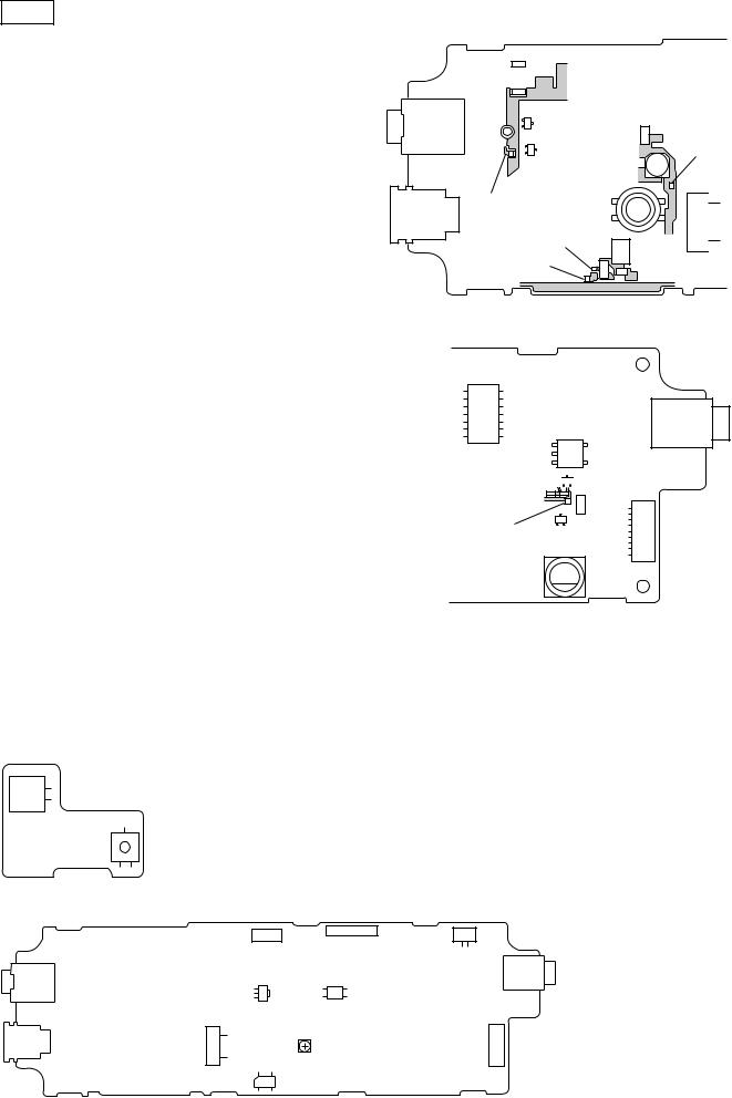
YM-11P E / F
1.ON LED
2.YM-11P E / F CL
J1011 GND
|
|
|
|
V 5.0V |
|
|
CL305 |
|
4.85±0.1V |
D 5.0V |
|
|
CL307 |
|
4.95±0.1V |
13.5V |
|
|
CL306 |
|
13.50±0.1V |
AU 2.0V |
|
|
CL308 |
|
1.85±0.1V |
BL 7.0V |
|
|
CL310 |
|
7.00±0.01V |
3.SW-312 E / F S705
又はYM-11P E / F CN9031 2
LED
4.YM-11P E / F CN3011 8.4 ±0.1V
5.3
SW-312 E / F
CN702
S705
YM-11P E / F
J101 |
LND305 |
Q391 |
|
||
|
|
|
|
|
Q392 |
CL308
|
L310 |
|
CL307 |
L307 |
|
CL306 |
||
|
FL252

 Q254
Q254
CL305
Q261
L601
YM-11P E / F
CN903
1 2
CN301
5
1
CL310
CN301
2-2
 Loading...