


4-745-630-11 (1)
Color Camera
Operating Instructions
Before operating the unit, please read this manual thoroughly and retain it for future reference.
HDC3500
© 2018 Sony Corporation

Table of Contents |
|
Overview..................................................................... |
3 |
Supported Formats .......................................................... |
3 |
System Configuration....................................................... |
4 |
Locations and Functions of Parts............................ |
6 |
Accessory Attachments.................................................... |
6 |
Controls and Connectors ................................................. |
6 |
Preparations............................................................. |
12 |
Attaching a Lens ............................................................ |
12 |
Adjusting the Flange Focal Length................................. |
12 |
Attaching a Viewfinder ................................................... |
12 |
Attaching the Cable Clamp Belt (Supplied).................... |
13 |
Adjusting the Shoulder Pad Position.............................. |
14 |
Mounting the Camera to a Tripod .................................. |
14 |
Adjustments and Settings for Shooting................ |
15 |
Adjusting the Black Balance and White Balance ........... |
15 |
Setting the Electronic Shutter......................................... |
17 |
Setting the Focus Assist Functions ................................ |
18 |
Setting the Focus Position Meter Function .................... |
19 |
Setting the Camera Outputs ................................... |
21 |
Viewfinder Screen Status Display.......................... |
22 |
Menu Operations ..................................................... |
23 |
Starting Menu Operations .............................................. |
23 |
Selecting Pages ............................................................. |
24 |
Setting the Menu Items .................................................. |
24 |
Editing the USER Menu ................................................. |
25 |
Menu List.................................................................. |
28 |
Menu Tree...................................................................... |
28 |
OPERATION Menu ........................................................ |
33 |
PAINT Menu................................................................... |
44 |
MAINTENANCE Menu ................................................... |
47 |
FILE Menu...................................................................... |
51 |
DIAGNOSIS Menu ......................................................... |
53 |
Appendix .................................................................. |
55 |
Precautions .................................................................... |
55 |
Digital Triax Transmission (when HKC-TR37 is |
|
attached)..................................................................... |
55 |
Error Messages.............................................................. |
56 |
Using a USB Drive ................................................... |
57 |
Specifications .......................................................... |
58 |
HDC3500 ....................................................................... |
58 |
Optional Accessories/Related Equipment...................... |
58 |
HKC-FB30...................................................................... |
59 |
HKC-TR37...................................................................... |
59 |
HKC-CN50 ..................................................................... |
59 |
Dimensions .................................................................... |
60 |
2
Overview
The HDC3500 is a color camera equipped with a newly developed 2/3 inch CMOS sensor with global shutter for F10 (1080/ 59.94P)/F11 (1080/50P) high sensitivity and high signal-to-noise ratio.
Operation as a studio camera is supported when connected with an HDCU3100 a) or HDCU2000-series b) Camera Control Unit (CCU) using fiber cables. Triax cable connection between the unit and HDCU3170 Camera Control Unit is also supported by replacing the transmission adaptor side panel with an HKC-TR37 Triax Transmission Adaptor c) (option).
a)Use HDCU3100 software version 2.00 or later.
b)Use HDCU2000-series software version 3.30 or later.
c)The HKC-CN50 Side Panel Attachment Kit (option) is required in order to use the HKC-TR37 Triax Transmission Adaptor.
Note
Before starting system operation, check that the software version and ROM version of the unit and system devices meet the version requirements.
Supported Formats
The unit supports 1080-59.94i, 1080-50i, 720-59.94P, and 720-50P formats as standard.
(When an HKC-TR37 is attached to the unit, 1080-59.94P and 1080-50P formats are supported as standard.) You can extend the formats that are supported by installing the following camera operating software (option).
For details, contact a Sony service or sales representative.
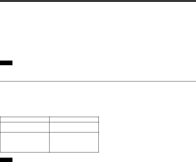
Camera operating software |
Extended formats |
|
|
HZC-PRV50/PRV50M/PRV50W 1080-59.94P 1080-50P
HZC-PSF50/PSF50M/PSF50W 1080-24PsF 1080-23.98PsF 1080-25PsF 1080-29.97PsF
Notes
•HZC-PRV50M/PSF50M are 30-day software licenses.
•HZC-PRV50W/PSF50W are 7-day software licenses.
•When an HKC-TR37 is attached to the unit, HZC-PSF50/PSF50M/PSF50W cannot be installed.
3
System Configuration
Note
Production of some of the peripherals and related devices shown in the figures has been discontinued. For advice on choosing devices, please contact your Sony dealer or a Sony sales representative.
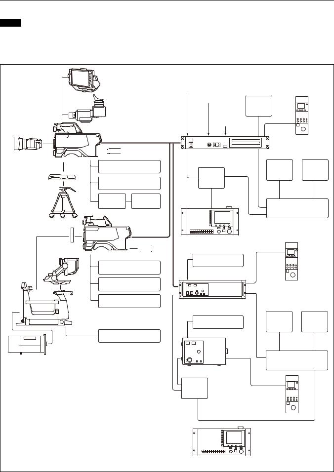
Connection example (optical fiber transmission)
HDVF-EL75/L750/L770
Viewfinder
HDVF-EL20
HDVF-EL30
Viewfinder
Lens |
HDC3500 |
(for ENG/EFP) |
|
Optical fiber cable b)


 USB drive
CAC-6
VCT-14 Tripod Return Video Selector
Attachment
|
Intercom headset |
|
Tripod |
CAC-12 |
Microphone |
|
Microphone |
|
|
Holder |
|
HDC3500
Camera hangers a)
HDVF-EL70 |
|
Viewfinder |
USB drive |
|
CAC-6 |
|
Return Video Selector |
|
Intercom headset |
|
Microphone |
|
HDLA1500-series |
|
Large Lens Adaptor |
|
cableLAN |
|
BKP-7911 |
|
Script Holder |
Lens
(for studio camera use)
a)Supplied with HDLA1500 series (Part No.: A-1128-405-A)
b)Signal transfer up to a maximum of 2 km is possible. However, the actual transfer distance may vary depending on the system configuration of the cameras and the type of optical fiber cables used.
c)Set the signal transmission rate for the camera to connect using the following menu item on the camera control unit.
SYSTEM CONFIG t <CAMERA I/F> t FIBER TRANSMIT RATE For details, refer to the operation manual of the camera control unit.
d)To use the HDCU3170, install the HKCU-FB30 Optical Fiber Connector Kit.
Sync signal input |
|
|
|
||
|
Return video input |
2K video |
|
|
|
|
|
|
|
||
|
Intercom |
monitor |
|
|
|
|
|
|
|
||
|
microphone |
|
CCA-5 |
|
|
|
input |
BNC |
|
||
|
|
|
|||
|
|
|
|
||
|
|
|
RCP-1500/1000 series |
||
|
|
|
Remote Control Panel |
||
cable |
HDCU3100, HDCU3170 d) |
|
|
|
|
Camera Control Unit c) |
|
|
|
||
|
|
|
|
||
LAN |
|
BNC |
Video |
Waveform |
|
Hub |
monitor |
monitor |
|||
|
|
||||
|
|
|
|
||
|
LAN cable |
|
|
|
|
|
|
|
Video router |
||
MSU-1000 series
Master Setup Unit
HKCU1001/1003/ |
|
CCA-5 |
|
|
|
|
|
||
2007/2040 |
|
|
|
|
|
|
RCP-1500/1000 series |
||
|
|
Remote Control Panel |
||
HDCU2000 |
|
|
|
|
Camera Control Unit |
|
|
|
|
HKCU1001/1003/ |
BNC |
Video |
Waveform |
|
2007/2040 |
monitor |
monitor |
||
|
||||
CCA-5
HDCU2500
Camera Control Unit
Hub
LAN cable
Video router
RCP-1500/1000 series
Remote Control Panel
MSU-1000 series Master Setup Unit
4
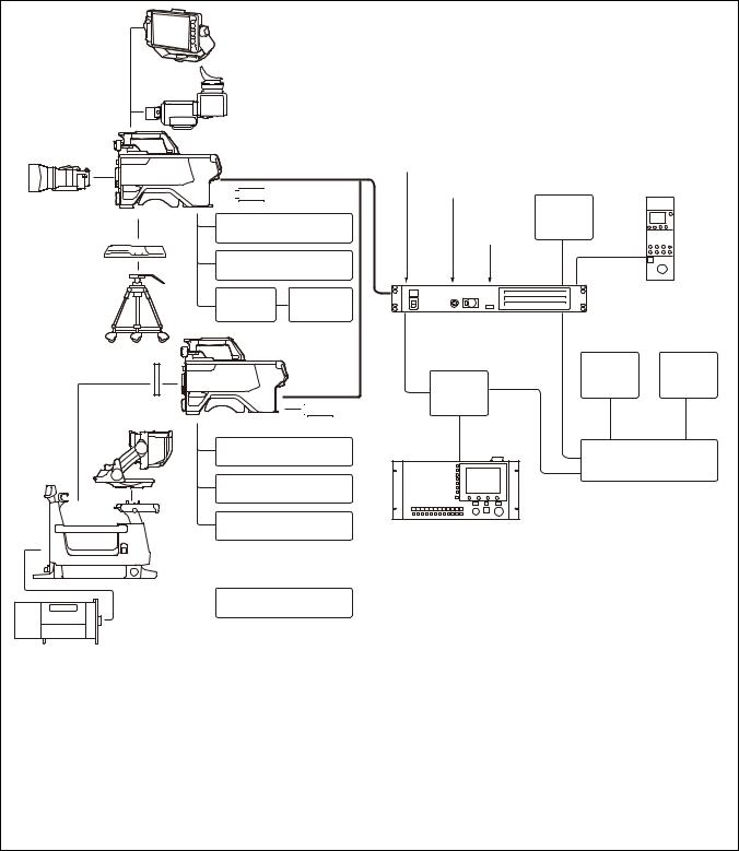
Connection example (digital triax)
HDVF-EL75/L750/L770
Viewfinder
HDVF-EL20
HDVF-EL30
Viewfinder
Lens |
HDC3500 b) |
(for ENG/EFP) |
|
Triax cable c)


 USB drive
CAC-6 Return Video
VCT-14 Tripod Selector
Attachment
|
Intercom headset |
Tripod |
CAC-12 |
|
Microphone Microphone |
|
Holder |
|
HDC3500 b) d) |
Camera hangers a) |
|
HDVF-EL70 |
|
Viewfinder |
USB drive |
|
CAC-6 Return Video |
|
Selector |
|
Intercom headset |
|
Microphone |
HDLA1500-series
Large Lens Adaptor
 BKP-7911
Script Holder
Lens
(for studio camera use)
Sync signal input |
|
||
|
Return video input |
|
|
|
Intercom |
2K video |
|
|
microphone |
monitor |
|
|
input |
|
|
|
|
BNC |
|
cableLAN |
HDCU3170 e) |
BNC |
|
Camera Control Unit |
|||
|
|
||
|
Hub |
|
|
|
LAN cable |
|
|
MSU-1000 series
Master Setup Unit
CCA-5
RCP-1500/1000 series Remote Control Panel
Video |
Waveform |
monitor |
monitor |
Video router
a)Supplied with HDLA1500 series (Part No.: A-1128-405-A)
b)Attach the HKC-TR37 Triax Transmission Adaptor and HKC-CN50 Side Panel Attachment Kit (option).
c)Signal transfer up to a maximum of 1.8 km is possible. However, the actual transfer distance may vary depending on the system configuration of the cameras and the type of triax cables used.
For details, see page 55.
d)When using the HDLA1500 series, external DC power supply is not available.
e)Set the signal protocol using the following menu item on the camera control unit. SYSTEM CONFIG t <CAMERA I/F> t TRIAX TRANSMIT
For details, refer to the operation manual of the camera control unit.
5
Locations and Functions of Parts
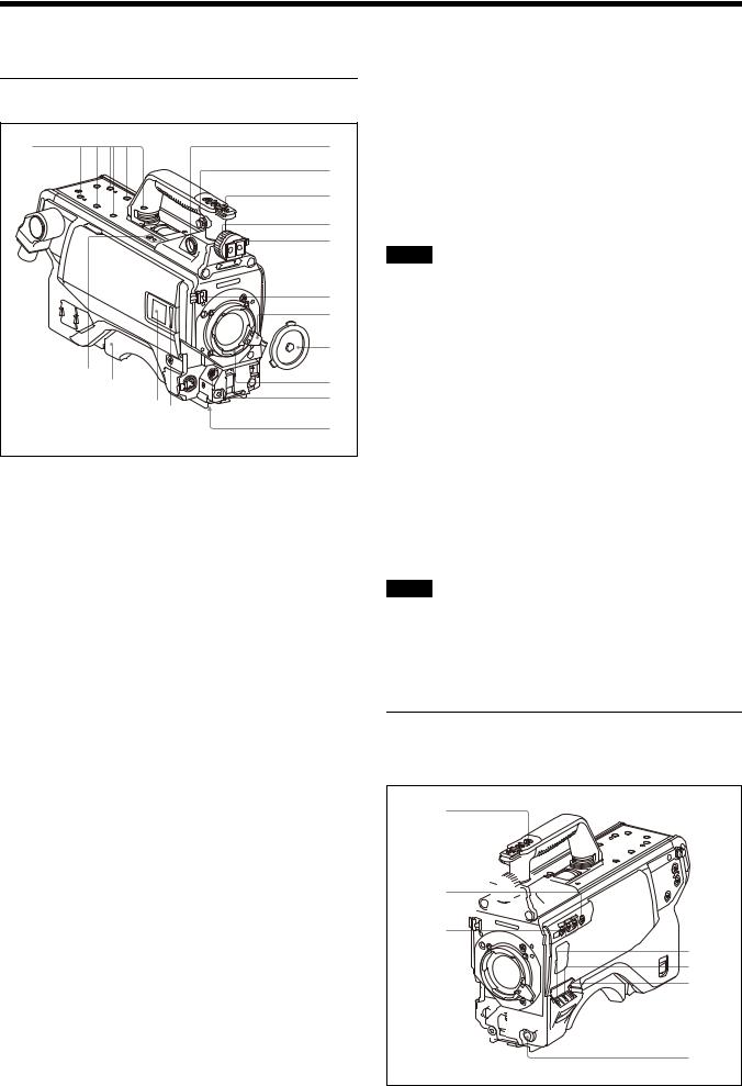
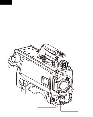
Accessory Attachments
p |
a |
|
b |
|
c |
|
d |
|
e |
|
f |
|
g |
|
h |
o |
i |
n |
|
|
j |
|
ml |
|
k |
a VF (viewfinder) connector (20-pin)
Connect the cable of the viewfinder (not supplied).
b Shoulder strap fitting post
Attach one end of a shoulder strap (not supplied) to this fitting post, and the other end to the fitting post on the other side of the camera.
c Accessory shoe
To attach an accessory using a 1/4-inch screw.
d Viewfinder left-right positioning ring
Loosen this ring to adjust the viewfinder position towards the left or right.
e Viewfinder front-rear positioning lever
Unlock the front-rear positioning lever to adjust the viewfinder position towards the front or rear, then lock in the desired position.
For details on adjusting the viewfinder position, see “Attaching a Viewfinder” on page 12.
f Lens cable clamp
To secure the cable of the lens (not supplied).
g Lens fixing lever
To secure the lens in the lens mount.
h Lens mount cap
The cover can be removed by moving the lens fixing lever upwards. Always keep the lens mount covered with this cap when a lens is not attached.
i Lens mount
To attach a lens.
j LENS connector (12-pin)
Connect the lens cable. The camera can control the lens functions through this cable.
k Tripod mount
Attach the VCT-14 Tripod Attachment when mounting the camera on a tripod.
l LED lamp
Use as a tally. You can switch the function using the menu.
m Camera number
The unit uses electronic paper (e-ink) type camera numbers. You can set the camera number using the menu.
Note
The operating temperature range of the camera number setting is 0 °C to 45 °C (32 °F to 113 °F). The setting may not be configurable if the temperature range is exceeded. Check the temperature when configuring.
n Shoulder pad
You can adjust the position so that you can get the best balance for shooting with the camera on your shoulder.
For details, see “Adjusting the Shoulder Pad Position” on page 14.
o Microphone holder attachment
Use to attach a CAC-12 Microphone Holder.
For details, refer to the microphone holder operation manual.
p V-wedge shoe attachment points
Attach a V-wedge shoe here to mount an HDVF-EL75/L750/ L770 Viewfinder.
Note
Select either the front or rear V-wedge shoe attachment points to attach the V-wedge shoe. If the front position is used, it may restrict the tilt/pan angle available for the viewfinder.
For details about attachment, refer to the operation manual of the viewfinder.
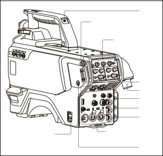
Controls and Connectors
Front right
a b
c 


 d
d

e
g
h
i


 j f
j f


 k
k
l
6
a INCOM1 (intercom 1) button
The intercom 1 microphone is turned ON while this button is held pressed.
You can also assign other functions to this button, using the menu displayed on the viewfinder screen.
b RET 1 (return video 1) button
The return video 1 signal from the camera control unit is monitored on the viewfinder screen while this button is pressed. It function the same as the RET 1 button on the side (page 8) and RET/ASSIGNABLE button A on the operation panel on the rear of the camera (page 9 or 10).
You can also assign other functions to this button, using the menu displayed on the viewfinder screen.
c Assignable switch
You can assign a function using the menu displayed on the viewfinder screen.
You can also display the assigned function name by attaching the corresponding label (supplied) for the assigned function.
d Filter select buttons
You can switch the built-in ND and CC (color temperature conversion) filters by pressing the selectors while holding the FILTER LOCAL button depressed.
Pressing the left button selects the available ND filters (CLEAR, 1/4ND, 1/8ND, 1/16ND,1/64ND) in sequence. Pressing the right button selects the available CC filters (cross, 3200K, 4300K, 6300K) in sequence.
e FILTER LOCAL button
While holding this button depressed, press either of the filter select buttons to select the built-in optical filters.
f AUTO W/B BAL (white and black balance automatic adjustment) switch
To automatically adjust white and black balance when the camera is used in standalone status without connecting to the camera control unit.
WHT: Automatically adjust white balance. BLK: Automatically adjust black balance.
g GAIN switch
To select the gain of the video amplifier based on lighting conditions when the camera is used in standalone status without connecting a camera control unit.
When shipped from the factory, the values set are L = 0 dB, M = 6 dB, and H = 12 dB.
h OUTPUT (output signal selection)/AUTO KNEE switch
To select the signal (color bar signal or camera’s video signal) to be used as output to the viewfinder or a video monitor when the camera is used in standalone status without connecting a camera control unit.
When the camera’s video signal is being used as output, the auto knee function may be used.
The relationship between the switch setting and the output signal and auto knee function is shown in the table below.
OUTPUT |
AUTO KNEE |
Function |
BARS |
OFF |
Output is a color bar signal. |
|
|
|
CAM |
OFF |
Output is the camera’s video signal. |
|
|
The auto knee circuit is disabled. |
|
|
|
CAM |
ON |
Output is the camera’s video signal. |
|
|
The auto knee circuit is enabled. |
|
|
|
i WHITE BAL (white balance memory selection) switch
To select the white balance adjustment method or the memory used to store the adjusted value when the camera is used in standalone status without connecting a camera control unit.
PRST (preset): White balance is adjusted to a preset value corresponding to a color temperature of 3200K.
A or B: Selects memory A or B.
j DISPLAY switch
The functions of the DISPLAY switch are as follows: DISPLAY: Characters and messages showing the camera
settings and operating status may be displayed on the viewfinder screen.
OFF: Status messages will not appear on the viewfinder screen.
MENU: Menus for camera settings will be displayed on the viewfinder screen.
k STATUS/CANCEL switch
STATUS: When no menu is displayed on the viewfinder screen, the status information of this camera is displayed.
CANCEL: When a menu is displayed on the viewfinder screen, you can cancel any changed settings or return the display to the previous menu.
lMENU SEL (menu select) knob/ENTER button (rotary encoder)
To select settings from menus displayed on the viewfinder screen (by rotating the knob) and to confirm settings (by pushing the button).
You can change the ECS frequency by pushing the ENTER button when no menu is displayed on the viewfinder screen. Make sure that the camera is used in standalone status without connecting a camera control unit, and the shutter mode is set to ECS. When the camera is used in standalone status and the shutter mode is set to other than ECS, the VF DETAIL function can be adjusted.
Note
When a camera control unit or a remote control device, such as an MSU or RCP-series Remote Control Panel, is connected, the functions of 6 to 9 are controlled from the external control device and the controls on the camera are disabled.
Front left
ab |
c |
f |
|
||
|
|
|
|
d |
|
|
e |
g |
|
|
h |
7
aNETWORK TRUNK connector (RJ-45 8-pin) (common to HKC-FB30)
Connects a device connected to the CCU’s NETWORK TRUNK connector to the network.
b DC power supply out connector (2-pin) (common to
HKC-TR37/HKC-FB30)
Supplies power to an external device up to 2.5 A.
c RET 1 (return video 1) button
The return video 1 signal from the camera control unit is monitored on the viewfinder screen while this button is pressed. It function the same as the RET 1 button on the handle (page 7) and RET/ASSIGNABLE button A on the operation panel on the rear of the camera (page 9 or 10). You can also assign other functions to this button, using the menu displayed on the viewfinder screen.
d MIC 1 IN (microphone 1 input) connector (XLR 3-pin)
Connect a microphone.
This connector and the AUDIO IN CH-1 connector (page 11) on the operation panel on the rear of the camera are alternately activated with the CH1 audio input select switch (page 11).
e MIC (microphone) power switch
+48V: To supply a power of +48 V to the connected microphone.
OFF: Not to supply a power to the connected microphone.
f SHUTTER switch
For setting the electronic shutter functions when the camera is used in standalone status without connecting a camera control unit.
OFF: The electronic shutter does not function. ON: The electronic shutter is activated.
SEL: The shutter speed and shutter mode change each time the switch is set to this position.
For details, see “Setting the Electronic Shutter” on page 17.
g INTERCOM LEVEL control
To adjust the intercom/earphone volume level. The intercom level adjustment is enabled when the
INTERCOM 1 and 2 LEVEL/MIC switches (on the UCJ model operation panel, page 9) or the LEVEL switch (on the
CE model operation panel, page 10) on the rear of the camera are set to “FRONT.”
h RET 2 (return video 2) button
When this button is pressed, the picture on the viewfinder screen changes to the return video signal selected using RET/ ASSIGNABLE button A, B, or C on the operation panel on the rear of the camera or using the menu.
You can also assign other functions to this button, using the menu displayed on the viewfinder screen.
Rear |
|
|
|
b |
|
|
Shoulder strap fitting |
|
|
post (page 6) |
|
|
Operation panel |
|
|
(page 9) |
|
|
c |
|
|
d |
|
|
e |
|
|
f |
|
|
g |
|
a |
Connector panel |
|
(page 10) |
||
|
||
|
h |
|
a CAMERA POWER switch |
|
CCU: Power is supplied from the camera control unit. EXT: Power is supplied through the DC IN connector.
b Tally lamp and switch
ON: The tally lamp lights when a tally signal is input to the connected camera control unit or a call signal is generated in response to pressing of a CALL button.
OFF: The tally lamp is prevented from lighting.
c RET 1/2 (return video 1/2) buttons
When pressed, the picture on the viewfinder screen changes to the return video signal selected using the operation panel on the rear of the camera or using the menu.
d CCU (camera control unit) connector HDC3500/HKC-FB30: Connect a camera control unit using
an optical electrical multi cable.
When HKC-TR37 is attached: Connect a camera control unit using a triax cable.
e SDI 1 (serial digital interface 1) connector (BNC-type)
(common to HKC-FB30)
For 3G SDI, HD SDI or HD PROMPTER signal output.
For details on the output signals, see “Setting the Camera Outputs” (page 21).
fSDI 2 (serial digital interface 2) connector (BNC-type) (common to HKC-FB30)
For 3G SDI or HD SDI signal output, or HD TRUNK signal input.
During stand-alone operation, also used for inputting an HD SDI return signal. When RET (return) is set to 1, this is displayed in the viewfinder.
g-1 PROMPTER2 connector (BNC-type) HDC3500/HKC-FB30: For prompter 2 signal output. Available
only when connecting a camera control unit with a prompter 2 input connector.
g-2 SDI (serial digital interface) connector (BNC-type) When HKC-TR37 is attached: 3G SDI signal or HD TRUNK
signal input.
8
h CALL button
When this button is pressed, the red tally lamp of the RCP-1500/1000 series Remote Control Panel or the MSU-1000-series Master Setup Unit will light. Use to call the operator of the RCP or MSU.
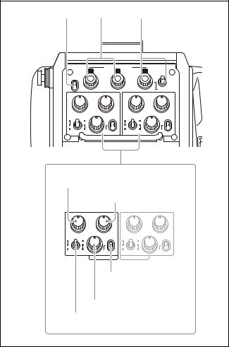
Operation panel
UCJ model: For USA, Canada, East Asia and other
countries |
|
|
|
|
|
|
b |
|
c |
|
d |
|
|
|
|
RET/ASSIGNABLE |
|
|
|
|
|
A |
B |
|
C |
|
|
LIGHT |
|
|
|
DISP |
|
|
ON |
|
|
|
|
|
|
|
OFF |
|
|
|
MENU |
|
PGM1 |
PGM2 |
PGM1 |
PGM2 |
|||
LEVEL |
MIC |
INCOM PROD |
LEVEL |
MIC |
INCOM |
PROD |
REAR |
ON |
|
REAR |
ON |
|
|
FRONT |
OFF |
MIX |
FRONT OFF |
MIX |
|
|
ENG |
|
ENG |
||||
|
|
|
|
|
||
a |
|
|
|
|
|
|
PGM1 control |
|
|
|
|
||
|
|
PGM2 control |
|
|
||
LEVEL |
MIC |
INCOM PROD |
LEVEL |
MIC |
INCOM |
PROD |
REAR |
ON |
|
REAR |
ON |
|
|
FRONT |
OFF |
MIX |
FRONT |
OFF |
MIX |
|
ENG |
|
ENG |
||||
|
|
|
|
|
||
|
INTERCOM 1 |
INTERCOM 2 |
|
|
||
|
|
Line select / Receive |
||||
|
|
MIX select switch |
||||
|
INCOM level control |
|
||||
LEVEL/MIC switch |
|
|
|
|||
a INTERCOM 1 and INTERCOM 2 controls and switches
There are separate PGM1 and PGM2 controls, line select/ receive MIX select switch, LEVEL/MIC switch, and INCOM level control for both intercom line 1 and intercom line 2.
PGM1 (program 1) control
Adjust the audio listening level of program 1.
PGM2 (program 2) control
Adjust the audio listening level of program 2.
LEVEL/MIC switch
REAR/ON: The intercom headset microphone is turned on. The intercom audio listening level is adjusted with the INCOM level control.
REAR/OFF: The intercom headset microphone is turned off. The intercom audio listening level is adjusted with the INCOM level control.
FRONT/OFF: The intercom headset microphone is turned off. The intercom audio listening level is adjusted with the INCOM level control and the INTERCOM LEVEL control on the front of the camera (page 8).
INCOM level control
Adjust the intercom audio listening level.
Line select / Receive MIX select switch
Select the intercom line. PROD: Producer line ENG: Engineer line
MIX: Receive mixed PROD/ENG audio. Select the intercom talk line from the menu.
The default intercom line setting is ENG.
b LIGHT switch
Set to ON to illuminate the operation panel.
c RET/ASSIGNABLE button A, B
Press the button to switch the function assigned to the button on the <REAR FUNCTION ASSIGN> page on/off. When the return function is assigned, press the button to display the return video signal on the viewfinder screen while the button is pressed.
Turn the button to change the assigned function setting. When the return function is assigned, you can change the return signal channel.
d RET/ASSIGNABLE button C / DISP/MENU switch
Press the button to switch the function assigned to the button on the <REAR FUNCTION ASSIGN> page on/off. When the return function is assigned, press the button to display the return video signal on the viewfinder screen while the button is pressed.
Turn the button to change the assigned function setting. When the return function is assigned, you can change the return signal channel.
When the DISP/MENU switch is set to the MENU position to display the MENU screen, you can perform menu operations using RET/ASSIGNABLE button C.
9
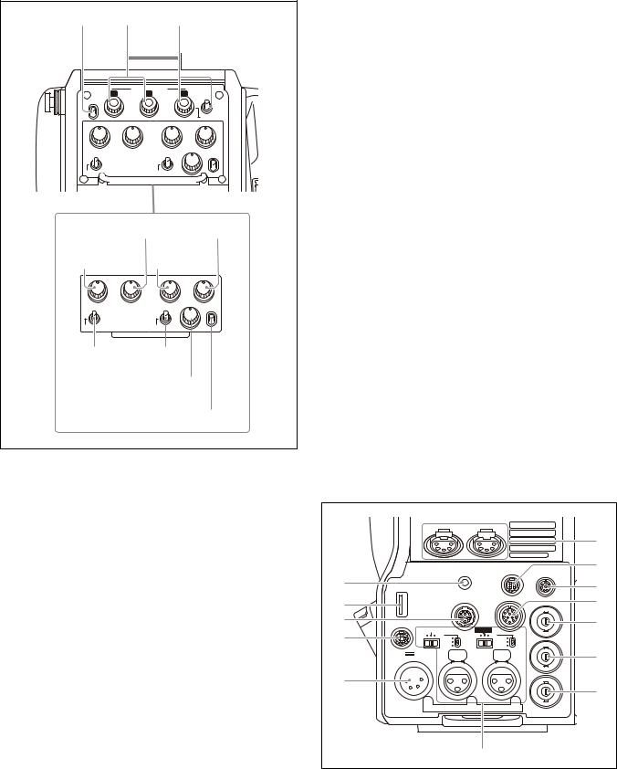
CE model: For Europe and South Asia
b |
|
c |
d |
|
|
|
RET/ASSIGNABLE |
|
|
|
A |
B |
C |
|
LIGHT |
|
|
DISP |
|
|
ON |
|
|
|
|
OFF |
|
|
MENU |
|
ENG |
PROD |
PGM1 |
PGM2 |
MIC |
PROD |
MIC |
PROD |
TRACKER LEVEL |
LINE1 |
LINE2 |
REAR |
||
OFF |
ENG |
OFF |
ENG |
FRT |
a |
|
|
|
|
|
PROD control |
PGM2 control |
||
ENG |
|
PGM1 |
|
|
control |
control |
|
||
|
ENG |
PROD |
PGM1 |
PGM2 |
MIC |
PROD |
MIC |
PROD |
TRACKERLEVEL |
LINE1 |
LINE2 |
REAR |
||
OFF |
ENG |
OFF |
ENG |
FRT |
|
INTERCOM 1 INTERCOM 2 |
|
||
MIC LINE1 |
MIC LINE2 |
|
||
switch |
switch |
|
|
|
|
|
TRACKER |
||
|
|
control |
|
|
|
|
LEVEL switch |
||
a INTERCOM 1 and INTERCOM 2 controls and switches
The reception level controls are common to intercom 1 and intercom 2. The talk lines can be set independently for intercom 1 and intercom 2.
ENG (engineer line) control:
Adjust the intercom audio listening level of the engineer line.
PROD (producer line) control
Adjust the intercom audio listening level of the producer line.
PGM1 (program 1) control
Adjust the audio listening level of program 1.
PGM2 (program 2) control
Adjust the audio listening level of program 2.
MIC LINE1 (intercom microphone line 1) switch
Select the talk line for intercom 1. PROD: To talk over the producer line
OFF: To turn off the headset microphone for intercom line 1.
ENG: To talk over the engineer line
MIC LINE2 (intercom microphone line 2) switch
Select the talk line for intercom 2. PROD: To talk over the producer line
OFF: To turn off the headset microphone for intercom line 2.
ENG: To talk over the engineer line
TRACKER control
Adjust the intercom audio listening level at the TRACKER connector (page 11) on the connector panel when using the connector for intercom.
LEVEL switch
REAR: The intercom audio listening level is adjusted with the controls on this panel.
FRT: The intercom audio listening level is adjusted with the INTERCOM LEVEL control on the front of the camera.
b LIGHT switch
Set to ON to illuminate the operation panel.
c RET/ASSIGNABLE button A, B
Press the button to switch the function assigned to the button on the <ROTARY ENCODER ASSIGN> page on/off. When the return function is assigned, press the button to display the return video signal on the viewfinder screen while the button is pressed.
Turn the button to change the assigned function setting. When the return function is assigned, you can change the return signal channel.
d RET/ASSIGNABLE button C / DISP/MENU switch
Press the button to switch the function assigned to the button on the <ROTARY ENCODER ASSIGN> page on/off. When the return function is assigned, press the button to display the return video signal on the viewfinder screen while the button is pressed.
Turn the button to change the assigned function setting. When the return function is assigned, you can change the return signal channel.
When the DISP/MENU switch is set to the MENU position to display the MENU screen, you can perform menu operations using RET/ASSIGNABLE button C.
Connector panel
|
|
|
|
|
|
f |
|
|
|
|
DC OUT |
REMOTE |
g |
|
|
|
EARPHONE |
|
||
|
|
|
|
|
||
a |
|
|
|
|
|
h |
|
|
|
|
|
|
|
b |
|
|
TRACKER |
CRANE |
|
i |
|
|
|
|
|||
|
|
|
|
PROMPTER |
||
|
|
|
|
/GEN |
|
|
c |
|
|
|
|
LOCK |
|
RET CTRL |
|
|
|
|
j |
|
d |
FRONT MIC |
AES/EBU |
|
|
||
LINE |
MIC |
LINE |
MIC |
TEST |
|
|
|
+48V |
|
+48V |
|
||
|
|
OFF |
|
OFF |
OUT |
|
|
DC IN 10.5-17V |
AUDIO IN |
|
|
k |
|
|
CH1 |
CH2 |
|
|||
|
|
|
|
|
||
e |
|
|
|
|
SDI |
|
|
|
|
|
MONI |
|
|
|
|
|
|
|
l |
|
|
|
|
|
|
|
|
|
|
|
m |
|
|
|
a EARPHONE jack (4-pole mini jack)
Connect to a headset, or earphones with microphone (3-pole/ 4-pole earphones), to input/output the intercom audio signal. For 4-pole earphones, the intercom line is linked to the INTERCOM1 setting.
Turn the microphone function on/off using HEADSET MIC (page 42) in the OPERATION menu. The default setting is OFF.
10
b USB connector (for connecting a USB drive)
Connect a USB drive to save or load the settings data file.
For details, see “Using a USB drive” (page 57).
c TRACKER connector (12-pin)
For external interface, such as intercom and tally.
d RET CTRL (return control) connector (6-pin)
For connection to a CAC-6 Return Video Selector.
e DC IN (DC power supply input) connector (XLR 4-pin)
Used for connection to the AC-DN10 AC Adaptor to supply power to the camera.
f INTERCOM1 and 2 (intercom 1 and 2) connectors (XLR
5-pin)
Used for input and output of intercom audio signals if an XLR 5-pin headset is connected.
The INTERCOM 1 connector can be used for communication over the engineer line even when the power is off, as long as the power LED is lit in red.
g DC OUT (DC power supply output) connector (4-pin)
To supply power to devices such as a wireless receiver (optional) (max. 0.5 A).
h REMOTE connector (8-pin)
For connection to an RCP-1500/1000 series Remote Control Panel, or MSU-1000/1500 Master Setup Unit.
Note
When the camera is connected to a CCU, do not connect any remote control device, such as RCP and MSU, to this connector.
i CRANE connector (12-pin)
For external interface, such as viewfinder and external data.
jPROMPTER/GENLOCK (prompter 1 signal output/ external gen-lock signal input) connector (BNC-type)
The PROMPTER function is enabled when a camera control unit is connected. The GENLOCK IN function is enabled when a camera control unit is not connected.
GENLOCK IN: For input of an external gen-lock signal (VBS or 3-level sync) during stand-alone operation.
PROMPTER: For output of the prompter 1 signal (valid only when a camera control unit is connected). When a camera control unit having two prompter inputs is connected, the signal of input 1 is output from this connector.
k TEST OUT connector (BNC-type)
To output the analog signal.
This can also output a VBS signal, HD-SYNC signal, or SD-SYNC signal, whichever is selected in the menu.
For details on the output signals, see “Setting the Camera Outputs” (page 21).
lSDI MONI (serial digital interface) connector (BNCtype)
For HD-SDI or SD-SDI signal output.
For details on the output signals, see “Setting the Camera Outputs” (page 21).
mAUDIO IN CH1 and CH2 connectors (XLR 3-pin) and switches
Connect audio signals. An input select switch and microphone power switch are provided for each channel.
CH1 audio input select switch
Microphone power switches
CH2 audio input select switch
FRONT MIC |
AES/EBU |
||
LINE |
MIC |
LINE |
MIC |
|
+48V |
|
+48V |
|
OFF |
|
OFF |
|
|
AUDIO IN |
|
|
|
CH1 |
CH2 |
AUDIO IN CH1 connector |
AUDIO IN CH2 connector |
CH1 audio input select switch
Set to the appropriate position according to the equipment connected to the AUDIO IN CH1 connector.
LINE: When a line-level (0 dBu) signal source is connected
FRONT MIC: When using the microphone connected to the MIC 1 IN connector
MIC: When an external microphone is connected
CH2 audio input select switch
Set to the appropriate position according to the equipment connected to the AUDIO IN CH2 connector.
LINE: When a line-level (0 dBu) signal source is connected
AES/EBU: When a digital audio signal is connected (The signal must be in synchronization with the camera output).
MIC: When an external microphone is connected
Microphone power switches
When a microphone is connected to the corresponding AUDIO IN connector, set whether or not to supply a power to the microphone.
+48V: To supply a power of +48 V OFF: Not to supply a power
(No function has been assigned to the lowermost position. No power is supplied to the microphone.)
Note
To supply +12 V power, contact a Sony sales representative or Sony service representative.
11
Preparations
Attaching a Lens
For information on handling lenses, refer to the lens’ operation manual.
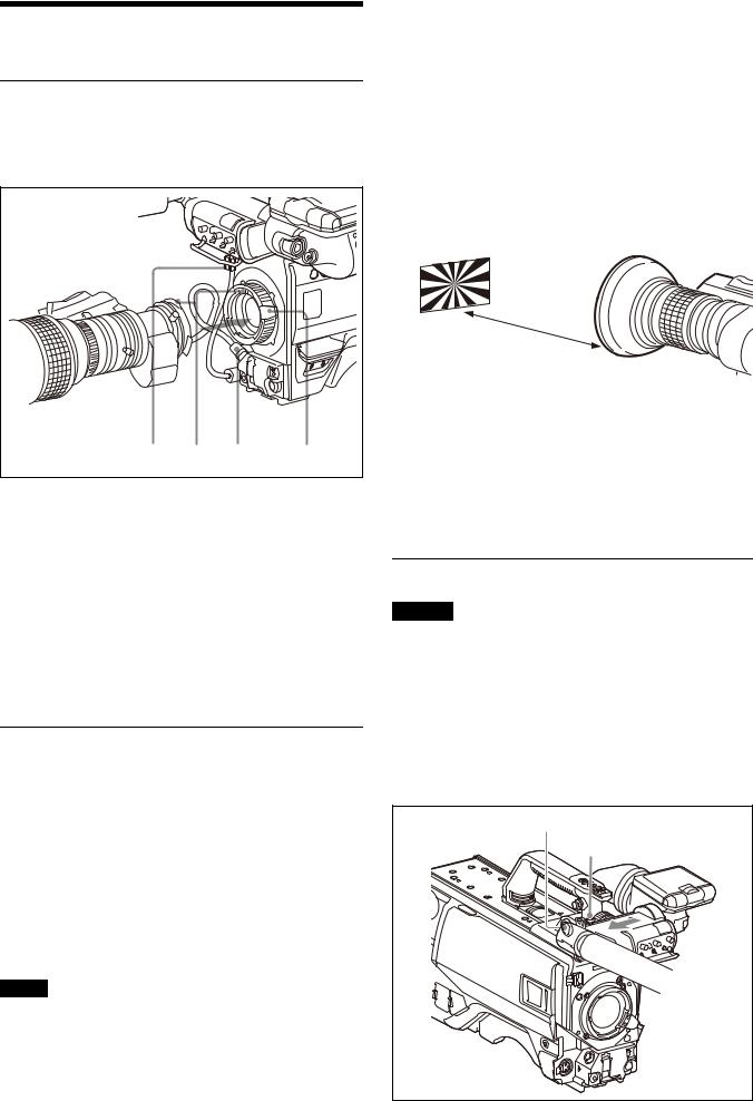
Attaching procedure
5 |
2 |
4 |
1,3 |
1 Push the lens fixing lever upwards and remove the lens mount cap from the lens mount.
2 Align the lens’ alignment pin with the notch in the upper part of the lens mount and insert the lens into the mount.
3 While supporting the lens, push the lens fixing lever downwards to secure the lens.
4 Connect the lens cable to the LENS connector.
5 Secure the lens cable with the cable clamp.
Adjusting the Flange Focal Length
Adjustment of the flange focal length (the distance between the lens mount attachment plane and the imaging plane) is necessary in the following situations:
•The first time a lens is attached
•When changing lenses
•If the focus is not sharp at both telephoto and wide angle when zooming
The flange focal length can be more precisely adjusted by using the focus assist indicators.
See “Displaying the focus assist indicators” on page 19 for the focus assist indicators.
Note
The various parts of the lens used in adjusting the flange focal length are in different positions on different lenses. Refer to the operation manual for the particular lens.
Adjusting procedure
1 Set the iris control to manual, and open the iris fully.
2 Place a flange focal length adjustment chart approximately 3 meters from the camera and adjust the lighting to get an appropriate video output level.
3 Loosen the Ff (flange focal length) ring lock screw.
4 With either manual or power zoom, set the zoom ring to telephoto.
5 Aim at the flange focal length adjustment chart and turn the focus ring to focus the image.
About 3 meters (10 ft)
6 Set the zoom ring to wide angle.
7 Turn the Ff ring to bring the chart into focus. Take care not to move the distance ring.
8 Repeat steps 4 through 7 until the image is in focus at both telephoto and wide angle.
9 Tighten the Ff ring lock screw.
Attaching a Viewfinder
Caution
When the viewfinder is attached, do not leave the camera with the eyepiece facing the sun. Direct sunlight can enter through the eyepiece, be focused in the viewfinder and cause fire.
Attaching a viewfinder
This section describes using a HDVF-20A/200/EL20/EL30 (the HDVF-EL30 is shown in the diagrams).
For details on the viewfinder, refer to the operation manual of the viewfinder.
VF connector |
Viewfinder stopper |
12
1 Slide the viewfinder in the direction of the arrow.
The viewfinder stopper automatically pops down.
2 Loosen the viewfinder left-right positioning ring, slide the viewfinder side to side to the most convenient position and tighten the ring. (See “To adjust the position to the left or right” below.)
3 Connect the viewfinder cable to the VF connector of the camera.
Adjusting the viewfinder position
The viewfinder position may be adjusted towards the front and rear and to the left and right to make it easy to see into it.
To adjust the position to the left or right
Viewfinder left-right positioning ring
1 Loosen the viewfinder left-right positioning ring.
2 Slide the viewfinder left or right to move it into a good viewing position.
3 Tighten the viewfinder left-right positioning ring.
To adjust the position forward or backward
Viewfinder front-rear positioning lever
1 Set the viewfinder front-rear positioning lever to the unlocked position.
2 Slide the viewfinder towards the front or rear of the camera to move it into a good viewing position.
3 Set the viewfinder front-rear positioning lever to the lock position to secure the viewfinder.
Detaching the viewfinder
Loosen the viewfinder left-right positioning ring, pull the viewfinder stopper, then pull out the viewfinder by sliding it in the direction opposite to that when attached.
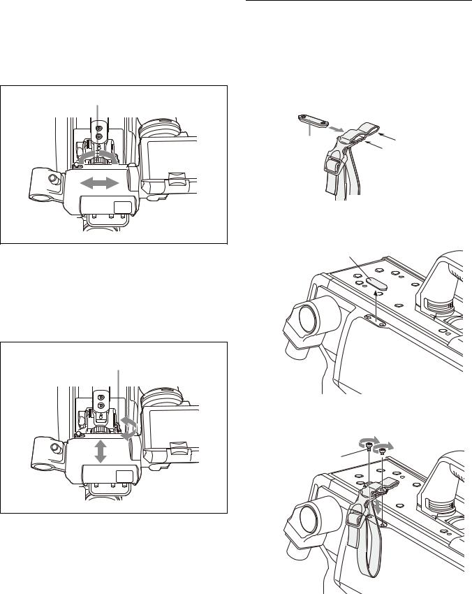
Attaching the Cable Clamp Belt (Supplied)
You can secure the optical/electrical multi cable or triax cable, connected to the CCU connector, to the side of the camera by attaching the supplied cable clamp belt.
1 Insert the belt bracket into hole A or B of the cable clamp belt.
Belt bracket |
B |
A
2 Peel off the cover seal from the camera as shown in the following diagram.
Cover seal
3 Secure the cable clamp belt to the camera, using the two supplied +B3×8 screws.
+B3×8 screws 

13

4 1 Release the buckle, 2 bundle the cable with the belt, 3 then lock the buckle again.
1
 3
3

2
Optical/electrical multi cable or triax cable
5 Adjust the length by pulling down the end of the belt.
Adjusting the Shoulder Pad Position
You can shift the shoulder pad from its center position (factory setting) backward by up to 10 mm (3/8 inch) or forward by up to 25 mm (1 inch). This adjustment helps you get the best balance for shooting with the camera on your shoulder.
Adjusting procedure
Shoulder pad lock lever |
||
|
1,3 |
|
Bottom of the camera |
2 |
Shoulder pad |
1 Raise the lever in the center of the shoulder pad to unlock the shoulder pad.
2 Slide the shoulder pad backward or forward until it is in the most convenient position.
3 Move the lever down to lock the shoulder pad in the selected position.
Mounting the Camera to a Tripod
Mount the camera to a tripod using a VCT-14 Tripod Attachment.
Caution
•Select an appropriate hole from among those at the bottom of the tripod attachment considering the balance of the weight of the camera and the tripod attachment. If an inappropriate hole is selected, the camera may fall over.
•Check that the size of the selected hole matches that of the screw of the tripod. If they do not match, the tripod attachment cannot be attached to the tripod securely.
Mounting procedure
1 Attach the tripod attachment to the tripod and secure it with the screw.
Tripod attachment
Platform of the tripod
14
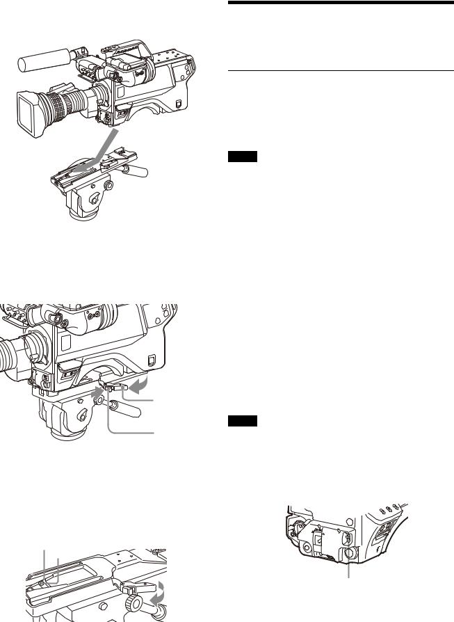
2 Place the camera on the tripod attachment, and slide forward it along the groove of the tripod attachment until it clicks.
3 Make sure that the camera is securely attached by moving it back and forth.
To remove the camera from the tripod attachment
Hold down the red button and pull the lever in the direction of the arrow.
Lever
Red button
If the pin of the tripod attachment does not return to its original position
After removing the camera, if the pin of the tripod attachment does not return to its original position, hold down the red button and move the lever in the direction of the arrow to return the pin to its original position. It is not possible to mount a camera with the pin not seated.
Original position
Pin
Adjustments and Settings for Shooting
Adjusting the Black Balance and White
Balance
In order to maintain high picture quality, it is necessary to set the black balance and white balance appropriately for the conditions.
Note
When a camera control unit or a remote control device-such as the MSU or RCP series-is connected, control is performed from the RCP/MSU, and the switches on the camera are disabled.
Black balance adjustment
The black balance needs adjustment in situations like the following:
•The first time the camera is used
•When the camera is used after a long period of disuse
•When the surrounding temperature changes greatly
•When the gain value is changed using the setup menus Normally, there is no need to adjust the black balance every time the camera is turned on.
White balance adjustment
Always readjust the white balance when lighting conditions change.
About the viewfinder screen
After the process of adjusting the black balance or white balance begins, messages about the progress and results of the adjustment will be displayed on the viewfinder screen.
Note
Adjusted values set through automatic adjustment, and other settings, are stored in the camera’s memory and preserved even when the camera power is turned off.
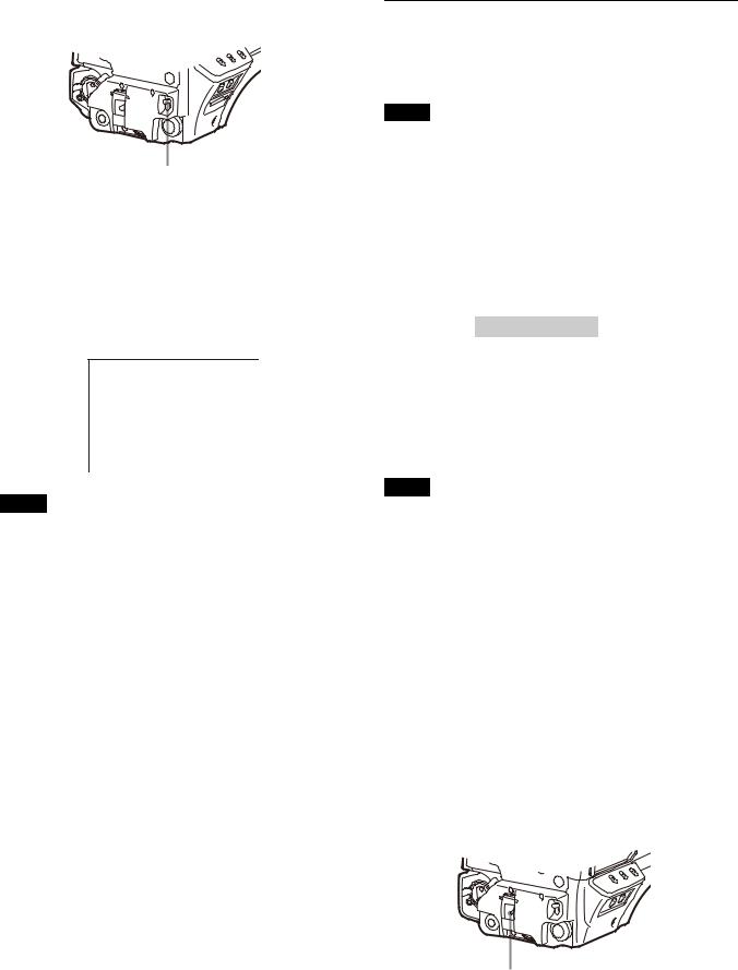
Adjusting the black balance
Push the AUTO W/B BAL switch toward BLK (downward).
AUTO W/B BAL switch
Automatic adjustment of black balance begins.
In automatic adjustment of black balance, both the black set and black balance are adjusted.
15
During adjustment, a message like the one in the figure below will be displayed on the viewfinder screen.
ABB:EXECUTING
When the adjustment process is completed, the message “ABB: OK” will be displayed. The adjusted value is automatically stored in memory.
Notes
•During black balance adjustment, the iris will be automatically closed.
•During black balance adjustment, the gain switching circuit will work automatically, and the viewfinder screen will flicker several times. This is not a malfunction.
When automatic black balance adjustment fails
If the automatic black balance adjustment process does not end successfully, the error message “ABB: NG” will be displayed on the viewfinder screen for approximately three seconds.
If this error message is displayed, try black balance adjustment again.
If the error message continues to be displayed after several attempts, the camera requires internal inspection.
About black balance memory
The black balance values stored in memory will be preserved even when the camera power is turned off.
Adjusting the white balance
1 Set the WHITE BAL switch to A or B.
WHITE BAL switch
|
|
|
CC filter select |
|
|
|
button |
|
|
|
ND filter select |
|
|
|
button |
|
|
|
FILTER LOCAL |
|
|
|
button |
ND filter |
Color temperature |
||
|
|
conversion filter |
|
1 |
CLEAR |
A |
cross filter |
2 |
1/4 ND |
B |
3200K (clear) |
3 |
1/8 ND |
C |
4300K |
4 |
1/16 ND |
D |
6300K |
5 |
1/64 ND |
|
|
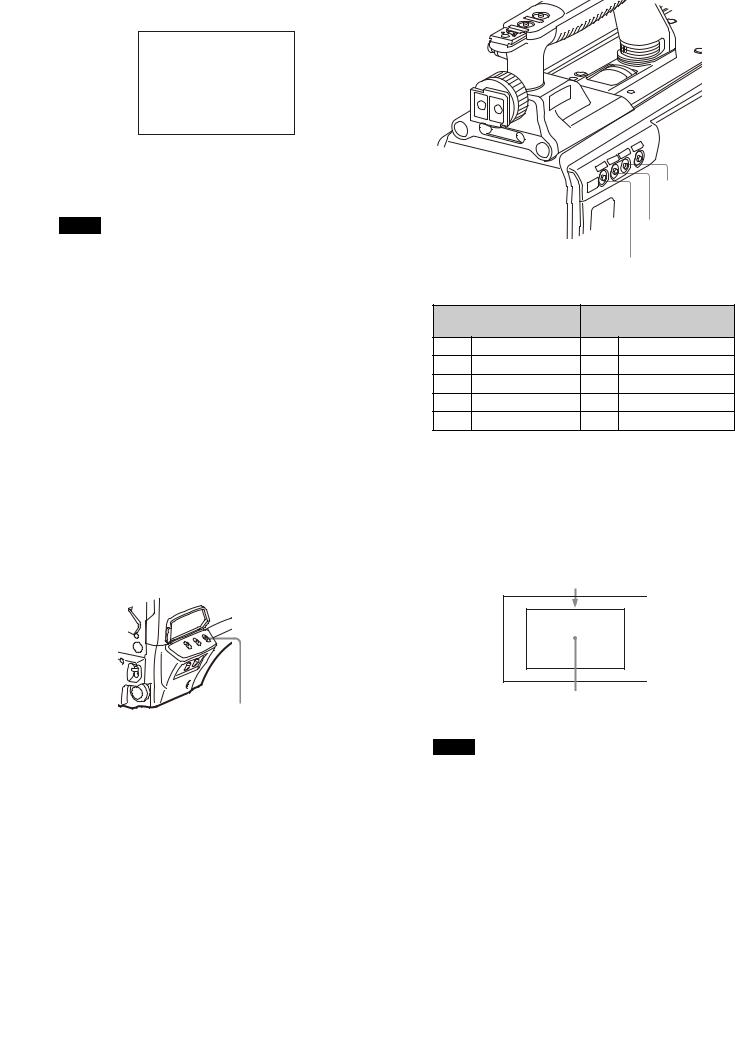
3 Place a white pattern in the same lighting conditions as the subject, and zoom in on it so that a white area is obtained in the screen to satisfy the positional and quantitative requirements illustrated below.
A white object (white cloth, a white wall, etc.) near the subject may be used in place of a white pattern.
A rectangle centered in the screen. The length of the sides must be at least 70% of the height and width of the screen.
Within this rectangle, there must be an area of white greater than 10% of the entire screen.
2 Select the filter setting according to the lighting conditions.
To select the ND filter
Press the ND filter select button while holding the FILTER LOCAL button depressed.
Each press of the select button switches the available ND filters (CLEAR, 1/4ND, 1/8ND, 1/16ND,1/64ND) in sequence.
To select the CC filter
Press the CC filter select button while holding the FILTER LOCAL button depressed.
Each press of the select button switches the available CC filters (cross, 3200K, 4300K, 6300K) in sequence.
Note
Be careful not to have any spots of high illumination in the rectangle.
4 Adjust the lens iris opening.
With a manually adjusted lens: Set the opening to an appropriate value.
With a lens which has automatic iris control: Set the lens’ automatic/manual iris control switch to automatic.
16
5 Push the AUTO W/B BAL switch to WHT and release the switch.
AUTO W/B BAL switch
The switch will return to the center position, and adjustment will be performed.
During adjustment, the message “AWB: EXECUTING” will be displayed on the viewfinder screen.
A message like the one in the figure below will be displayed, and the adjustment process will complete. The adjusted value will be automatically stored in the memory (A or B) selected in step 1.
AWB:OK
Setting the Electronic Shutter
This section explains the different modes which can be used for the electronic shutter and gives the procedures for setting the shutter mode and shutter speed.
Note
When a camera control unit or a remote control device, such as MSU-1000/1500 Master Setup Unit and RCP-1500/1000 series Remote Control Panel, is connected, the electronic shutter is controlled from the external control device and control on the camera are disabled.
About the shutter modes
The shutter modes that can be used with the electronic shutter of the camera and the shutter speeds that may be selected are as follows:
Shutter modes and speeds
Shutter mode |
Shutter speeds* |
Usage |
Standard |
1/100, 1/125, 1/250, |
Use to obtain clear images |
|
1/500, 1/1000, 1/2000 |
of quickly moving subjects |
|
seconds |
|
|
|
|
ECS (Extended |
Continuously variable in |
Use to obtain images on |
Clear Scan) |
the range of 59.96 Hz to |
video monitors without |
|
4300 Hz |
horizontal striping |
|
|
|
*The values in the table are those with 59.94i. With other formats, the available values are different.
Note
When using a zoom lens with automatic iris control capability, hunting1) may occur. Adjust the lens’ iris gain control (labeled IG, IS, S, etc.).
1)Hunting: The automatic iris responds over and over, and the image repeatedly darkens and lightens.
For more information, refer to the lens’ operation manual.
When automatic white balance adjustment fails
If the white balance adjustment process does not end successfully, the error message “AWB: NG” will be displayed on the viewfinder screen for approximately three seconds.
If this error message is displayed, try white balance adjustment again.
If the error message continues to be displayed after several attempts, the camera requires internal inspection.
When there is no time to adjust the white balance
Set the WHITE BAL switch to PRST. The white balance will be set automatically according to the filter settings.
About white balance memory
The white balance values stored in memory will be preserved even when the camera power is turned off.
There are two white balance memories, A and B. When the AUTO W/B BAL switch is pushed to the WHT side, the white balance will be adjusted automatically according to the filter settings. The adjusted value will be stored in the selected memory. Each memory can store up to five adjusted values, for a total of 10.
Note
With artificial lighting, particularly fluorescent lights and mercury vapor lamps, the brightness appears to be constant, but in fact the strength of the red, green, and blue components varies with the power supply frequency. This phenomenon is known as “flicker.” When using the electronic shutter under these lighting conditions, there are certain cases in which the flicker is more noticeable. In particular, color flicker is evident when the power frequency is 60 Hz. In areas where the power frequency is 50 Hz, setting the shutter speed to 1/100 second will reduce the flicker.
Selecting the shutter mode and speed
The shutter mode, and the shutter speed in standard mode, are set using the SHUTTER switch.
Setting the shutter mode, and shutter speed in Standard mode
1 Push the SHUTTER switch from the ON position to the SEL position.
SHUTTER switch
The current shutter setting will be displayed in the setting change/adjustment progress message display area of the viewfinder screen for about three seconds.
Example: “SHUTTER: 1/250”
17
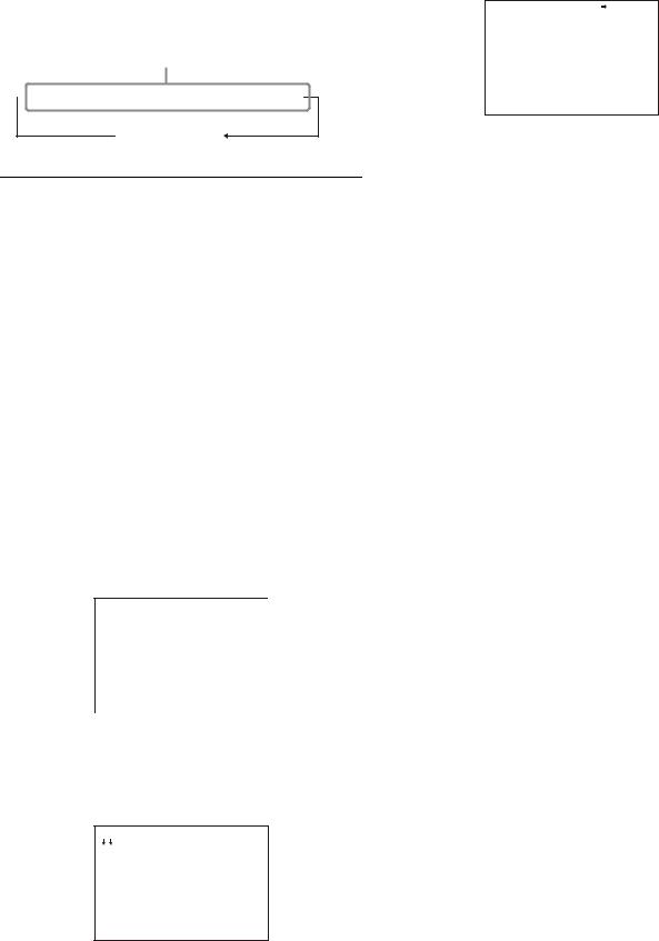
2 Push the SHUTTER switch to the SEL position again before the display disappears. Repeat this action until the desired mode or speed is displayed.
When all modes and speeds are displayed, they will be displayed in the following order:
Example: with 59.94i
Standard mode
 1/100
1/100  1/125
1/125  1/250
1/250  1/500
1/500  1/1000
  1/2000
ECS mode
Setting the Focus Assist Functions
Using the OPERATION menu, the assist functions for easier focusing on the viewfinder, can be activated.
Adding the VF detail signal
Adding the VF detail signal to sharp edges in the image on the viewfinder screen makes it easier to check the focusing condition by observing changes in the detail signal or in the color converted from the detail signal (color detail).
The focus setting where the detail signal becomes strongest is the best focus setting.
1 Turn on the camera.
2 Set the DISPLAY switch to MENU while holding the MENU SEL knob/ENTER button pressed.
The camera enters Menu mode, and “TOP” is displayed at the upper right corner of the screen.
3 Rotate the MENU SEL knob/ENTER button to align the arrow marker (,) to “TOP” and push on the MENU
SEL knob/ENTER button.
The TOP MENU screen is displayed.
<TOP MENU>
 USER
USER
USER MENU CUSTOMIZE
ALL
 OPERATION
 PAINT
PAINT
 MAINTENANCE
 FILE
FILE
 DIAGNOSIS
4 Rotate the MENU SEL knob/ENTER button to align the arrow marker (,) to OPERATION and push on the
MENU SEL knob/ENTER button.
The CONTENTS page of the OPERATION menu is displayed.
CONTENTS |
00 TOP |
 01.<VF DISPLAY> 02.<'!'IND> 03.<VF MARKER> 04.<VF DETAIL>
05.<FOCUS POSITION METER1 06.<FOCUS POSITION METER2 07.<FOCUS ASSIST> 08.<ZEBRA>
09.<CURSOR>
10.<BOX CURSOR FILE>
5 Rotate the MENU SEL knob/ENTER button to align the arrow marker (,) to <VF DETAIL> and push on the
MENU SEL knob/ENTER button.
The <VF DETAIL> page is displayed.
<VF |
DETAIL> |
|
04 TOP |
||
VF |
DETAIL |
: |
ON |
(25%) |
|
CRISP |
|
: |
0 |
|
|
FREQUENCY: |
9M |
|
|||
FLICKER |
: |
OFF |
|||
AREA |
|
: |
70% |
||
ZOOM |
LINK: |
ON |
100% |
||
COLOR |
DETAIL |
: |
ON BLUE |
||
PEAK |
COLOR |
: |
ON |
||
CHROMA LEVEL: |
100% |
||||
6 Rotate the MENU SEL knob/ENTER button to align the arrow marker (,) to the item to be set and push on the MENU SEL knob/ENTER button.
To use the VF detail signal
Set VF DETAIL to ON to activate the VF detail function to add the detail signal to sharp edges in the image. You can adjust the signal level (strength) in the range of 0 to 100% (default 25%).
You can adjust the characteristics of the detail signal with the menu items below.
CRISP: Adjust to eliminate fine portions of the detail signal.
FREQUENCY: Change the detection band of sharp edges.
FLICKER: Turn ON/OFF the function to flicker the detail signal, which makes it easier to check the signal on a viewfinder screen.
AREA: To limit the area where to display the detail signal. ZOOM LINK: Set the VF detail level at the full WIDE
position. (The VF detail level changes according to the zoom position.)
To use the color detail
Set COLOR DETAIL to ON to convert the VF detail signal to a specified color. This makes it easier to check the signal on an LCD screen, including the viewfinder screen. The display color can be selected at the column next to ON.
You can adjust the coloring with the menu items below. PEAK COLOR: Turn ON/OFF the function to change the
color where the detail signal is strongest. CHROMA LEVEL: To reduce the chroma components of
the video signal (only for video signals on the viewfinder).
7 Rotate the MENU SEL knob/ENTER button to display the desired setting and push on the MENU SEL knob/ ENTER button.
8 To finish the adjustment, set the DISPLAY switch to OFF to exit Menu mode.
18
 Loading...