


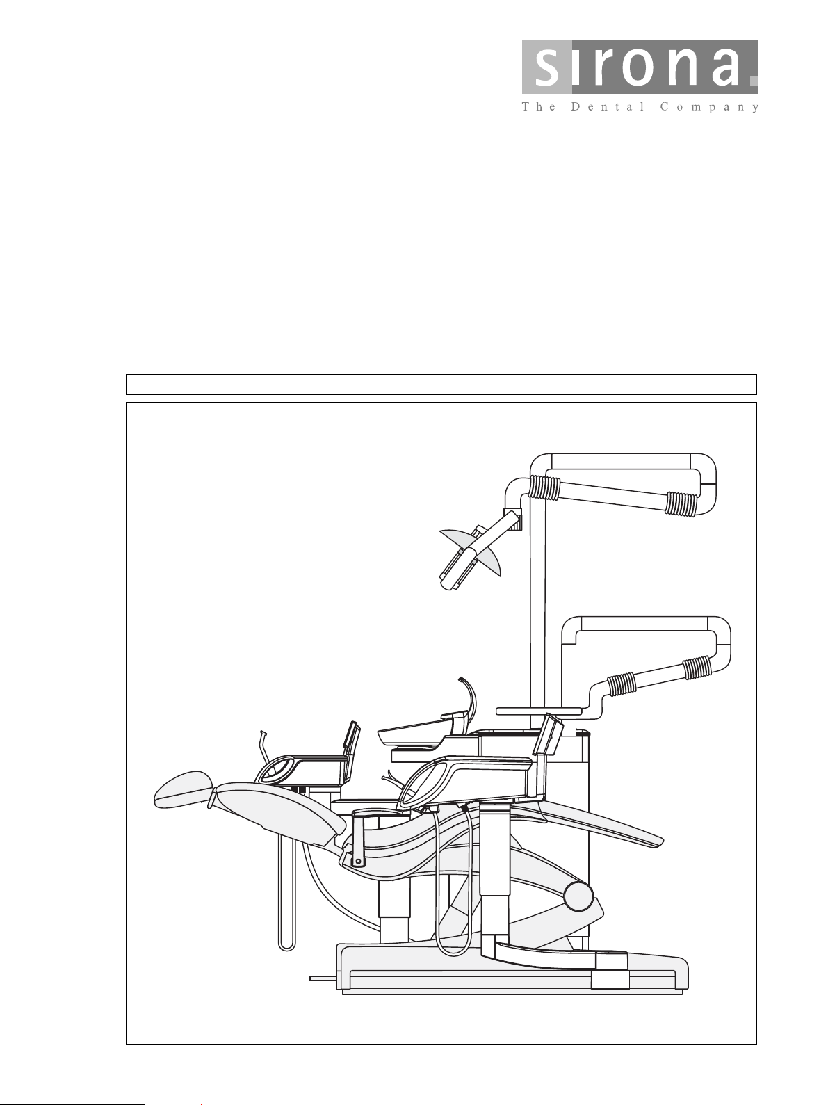
Teneo
qbkbl
pЙкобЕЙ=j~ем~д===== =
bеЦдблЬ

qbkbl
pЙкобЕЙ=j~ем~д===== =
bеЦдблЬ
IMPORTANT:
• In the case of faults which you are unable to eliminate with the
help of this manual, please contact our Customer Service Center.
• It is essential that you take this service manual and a service
laptop along with you on every customer call.
Furthermore, you must always have the spare parts list and wiring diagrams with you as well.
You can download this service manual in the dealer area of the Sirona
website.


Contents
1 Important information..................................................................................................... 1 – 1
1.1 Technical data.................................................................................................................................. 1 – 2
1.2 Warning and safety information ....................................................................................................... 1 – 3
1.3 Symbols ........................................................................................................................................... 1 – 4
1.4 Abbreviations ................................................................................................................................... 1 – 5
1.5 Where to save user-specific data in the TENEO.............................................................................. 1 – 6
1.6 Safety switches in the dental treatment center ................................................................................ 1 – 8
1.7 Removing the upholstery/arm rests from the patient chair............................................................... 1 – 9
1.8 Removing the cover panels of the patient chair...............................................................................1 – 10
1.9 Removing the cover panels of the support arm of the dentist element............................................ 1 – 11
1.10 Opening the dentist element ............................................................................................................ 1 – 12
1.11 Removing the user interface on the dentist element........................................................................ 1 – 13
1.12 Removing the NAK and NAB boards ............................................................................................... 1 – 14
1.13 Removing the NAR board for the X-ray viewer................................................................................ 1 – 15
1.14 Removing the cover panels of the support arm of the assistant element. ....................................... 1 – 16
1.15 Removing the cover panels of the assistant element....................................................................... 1 – 17
1.16 Removing the cover panels from the water unit...............................................................................1 – 18
2 Overview of modules and boards.................................................................................. 2 – 1
2.1 Locations of modules and boards.................................................................................................... 2 – 2
2.2 ... In the patient chair........................................................................................................................ 2 – 3
2.2.1 DCFU board - Motor control board................................................................................................................. 2 – 3
2.2.2 NSA board - Connection box ......................................................................................................................... 2 – 5
2.2.3 NSB board - Wireless base station ................................................................................................................ 2 – 8
2.2.4 NSC board - Seat connect ............................................................................................................................. 2 – 9
2.2.5 NSK board headrest....................................................................................................................................... 2 – 11
2.2.6 NSU board - USB connection to patient chair................................................................................................ 2 – 13
2.3 ... in the foot control.......................................................................................................................... 2 – 14
2.3.1 Wireless foot control....................................................................................................................................... 2 – 14
2.4 ... in the dentist element................................................................................................................... 2 – 15
2.4.1 CC board - instrument holder recognition in the dentist unit .......................................................................... 2 – 15
2.4.2 HF
2.4.3 NAC board - BL motor control ........................................................................................................................ 2 – 17
2.4.4 NAJ board - Dentist element control .............................................................................................................. 2 – 19
2.4.5 NAK board - User interface to dentist element baseboard and NAB board LED board................................. 2 – 21
2.4.6 NAL board - SL motor control ........................................................................................................................ 2 – 23
2.4.7 NAU board - USB connector to AE ................................................................................................................ 2 – 24
2.5 ... in the X-ray viewer ....................................................................................................................... 2 – 25
2.5.1 NAR board - X-ray viewer .............................................................................................................................. 2 – 25
2.6 ... in the assistant element ............................................................................................................... 2 – 26
2.6.1 NHE board - ASE control ............................................................................................................................... 2 – 26
2.6.2 NHT board - ASE user interface .................................................................................................................... 2 – 27
2.6.3 NOP board - 5 V power supply ...................................................................................................................... 2 – 28
2.7 ... in the water unit............................................................................................................................ 2 – 29
2.7.1 NWE board - Water unit control ..................................................................................................................... 2 – 29
2.7.2 NWM board - Automatic tumbler filling........................................................................................................... 2 – 32
+
board - Surgery module.......................................................................................................................... 2 – 16
bеЦдблЬ
3 Important information..................................................................................................... 3 – 1
3.1 Switching the dental treatment center ON/OFF............................................................................... 3 – 2
3.1.1 What happens when it is switched on?.......................................................................................................... 3 – 3
3.1.2 What happens when it is switched off?.......................................................................................................... 3 – 4
3.1.3 Signal path of the ON/OFF signal .................................................................................................................. 3 – 5
3.2 CAN BUS ......................................................................................................................................... 3 – 6
3.3 CAN BUS wiring diagram................................................................................................................. 3 – 7
3.4 Patient chair..................................................................................................................................... 3 – 8
3.4.1 Stand-alone installation function .................................................................................................................... 3 – 8
3.4.2 DCFU motor control ....................................................................................................................................... 3 – 8
3.4.3 Safety switches (For the locations of the safety switches see Section 1.6, Safety switches)........................ 3 – 8
61 94 448 D 3509
D 3509.076.01.01.02 07.2008
I

Table of contents
4 Service area .................................................................................................................. 4 – 1
4.1 Service area of the user interface .................................................................................................... 4 – 2
4.2 Dental treatment center information................................................................................................. 4 – 3
4.2.1 Dentist element configuration INFO............................................................................................................... 4 – 3
4.2.2 Assistant element configuration INFO........................................................................................................... 4 – 4
4.2.3 Patient chair configuration INFO.................................................................................................................... 4 – 4
4.2.4 Water unit configuration INFO....................................................................................................................... 4 – 5
4.3 Reading out service codes............................................................................................................... 4 – 6
4.4 Maintenance display......................................................................................................................... 4 – 7
4.5 Service support with the PC............................................................................................................. 4 – 8
5 Points to observe when replacing ................................................................................. 5 – 1
5.1 ... Boards.......................................................................................................................................... 5 – 2
5.1.1 ... DCFU board in the patient chair ................................................................................................................ 5 – 2
5.1.2 ... NSA board in the patient chair................................................................................................................... 5 – 3
5.1.3 ... NSK board in the patient chair................................................................................................................... 5 – 3
5.1.4 ... HF
5.1.5 ... NAJ board in the dentist element............................................................................................................... 5 – 4
5.1.6 ... NHE board in the assistant element .......................................................................................................... 5 – 4
5.1.7 ... NWE board in the water unit...................................................................................................................... 5 – 4
5.1.8 ... NAR board in the RÖBI ............................................................................................................................. 5 – 5
+
board in the dentist element............................................................................................................... 5 – 4
6 PC connection / Networking .......................................................................................... 6 – 1
6.1 Connection of a dental treatment center to the practice network..................................................... 6 – 2
6.2 PC control via SIUCOM plus............................................................................................................ 6 – 3
6.2.1 Control of PC programs via the treatment center .......................................................................................... 6 – 3
6.2.2 Ethernet connection is required..................................................................................................................... 6 – 3
6.2.3 Third-party programs can also be controlled in this manner.......................................................................... 6 – 3
II D 3509.076.01.01.02 07.2008
61 94 448 D 3509
TENEO
1 Important information

1 Important information
1.1
Model designation TENEO
Power supply 100 - 230 V 50/60 Hz,
115 V∼ 50/60 Hz
Nominal current 230 V 4.8 A
115 V 9.6 A
100 V 11 A
Nominal power output: 1100 W
Technical data
1 – 2 D 3509.076.01.01.02 07.2008
61 94 448 D 3509
1 Important information
1.2 Warning and safety information
Caution! Prior to opening the unit, connecting a measuring instrument or replacing
parts, switch the treatment center OFF.
Protective ground connection The building water supply is at protective ground potential and must not touch
the fuse box of the chair.
Warning! If there is a protective ground contact, the patient or user may be exposed to
tension in the event of a fault - risk of electric shock!
Operational reliability To ensure operational reliability, the use of mobile wireless phones in practice
or hospital environments must be prohibited.
Troubleshooting: If you encounter difficulties, search in the error catalog first and proceed
according to the instructions given there.
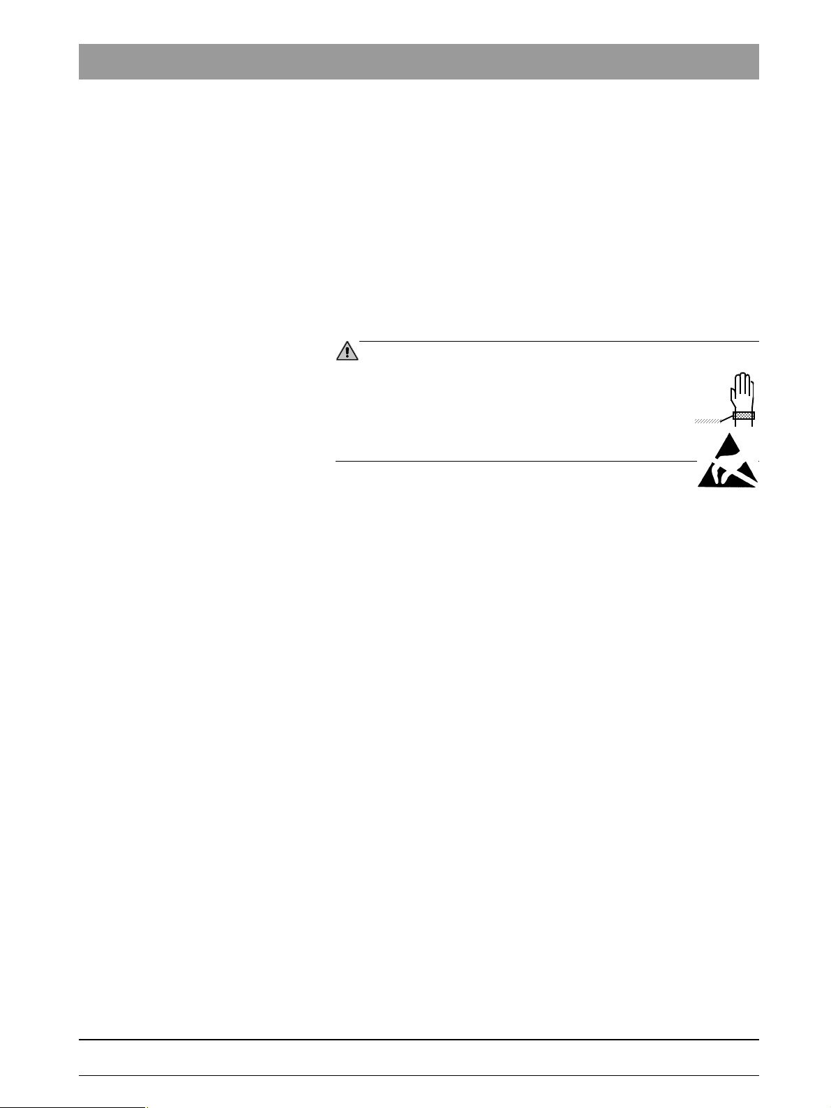
CAUTION
When opening the unit:
Please observe the usual precautionary measures for
handling printed circuit boards (ESD).
Touch a ground point to discharge static electricity before handling any components. Use an ESD wrist band.
Connect it to the protective ground wire.
bеЦдблЬ
61 94 448 D 3509
D 3509.076.01.01.02 07.2008
1 – 3
1 Important information
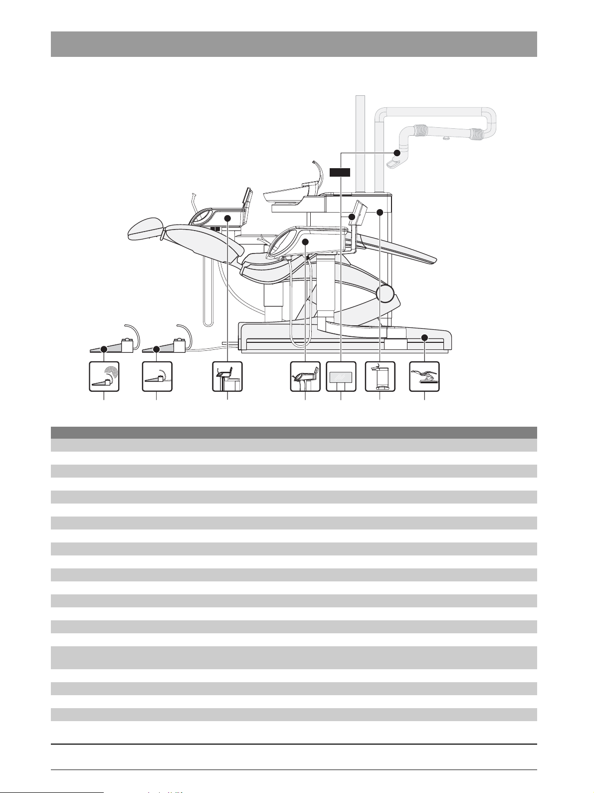
1.3
Dentist element
Assistant element
Foot control
Wireless foot control
Patient chair
Water unit
Symbols
1 – 4 D 3509.076.01.01.02 07.2008
61 94 448 D 3509
1 Important information
1.4 Abbreviations
AE Dentist element
AK Connection box
ASE Assistant element
BHE Dental treatment center
UI User interface
DNA Dürr wet suction system
PCB Printed circuit board
FS Foot control
FU Wireless foot control
GND Ground
HW Hardware
KS Four-way foot switch
LCable
LED Light emitting diode
LK Lumbar support cushion
MSBV Cuspidor valve
MV Solenoid valve
PC Personal computer
RÖBI X-ray image viewer
S Switch
SDI Sirona Dental Interface (electrical, pneumatic, hydraulic plug connection)
ST Patient chair
SW Software
VB Travel track
VDC DC voltage
WE Water unit
X Connector
bеЦдблЬ
61 94 448 D 3509
D 3509.076.01.01.02 07.2008
1 – 5
1 Important information
Board
Part No.
NAK
61 86 626
Board
Part No.
NWE
61 15 567
1.5
Stored settings
PC configuration
Date of last maintenance performed:
Display brightness
Key click
Time format
Current user
Number of users
White screen, switchable
Cursor mode
Number of chair programs
Manual chair setting at top level
Slow travel, switchable
Current timer
All timer values
All values that must be stored in conjunction with implantology/endodontics:
Number of implantology levels
NaCl cooling
NaCl rinsing amount
Instrument light
Selected endodontic file system
Auto-reverse
Handpiece
Speed
Torque
Endodontic file
Stored settings
Flushing duration
Tumbler filling time
Tumbler heating on/off
Tumbler heater temperature
Sirolux brightness
Amalgam separator filling level
AmalgamMotor operating time
SepaMotor operating time
MSBV opening time
Sanitation data
Where to save user-specific data in the TENEO
1 – 6 D 3509.076.01.01.02 07.2008
61 94 448 D 3509
1 Important information
Board
Part No.
NHE
61 15 583
Board
Part No.
NSA
61 15 591
Stored settings
NHE heater on/off
Heater temperature
Sprayvit instrument light
Sprayvit instrument light lamp voltage
Hydrocolloid duration
Stored settings
Central error storage
Tumbler filling on/off in S program
Flushing on/off in S program
SIROLUX status with chair programs
# key (switch/button)
Chair program 0, S, 1, 2 for dental user A-F
IP address
DHCP activated/deactivated
Serial numbers of the motor controls
Packaging position
Travel track positions
bеЦдблЬ
Board
Part No.
NAJ
61 28 446
Board
Part No.
DCFU
61 83 193
Stored settings
Sprayvit ventilation, AE
Activation times (instrument /instrument holder-dependent)
Instrument settings
Example:
Cooling, cooling mode, light, light intensity, foot control mode, direction of rotation,
NaCl cooling, speed, HF intensity, HF modulation
Stored settings
Minimum and maximum value of the permissible range of motion. Determined based on the reference travel.
Motor parameters
61 94 448 D 3509
D 3509.076.01.01.02 07.2008
1 – 7
1 Important information
X6
F1
F2
X29
X28
X30
X22
X21
X23
X24
X25
X15
X5
X27
X26
X18
X17
X16
X20
X19
X7
X4
X2
X1
X31
X13
F803
X14
X12
X19
X7X7
X4
X2
X11
X1
X3
X20
X13
X2
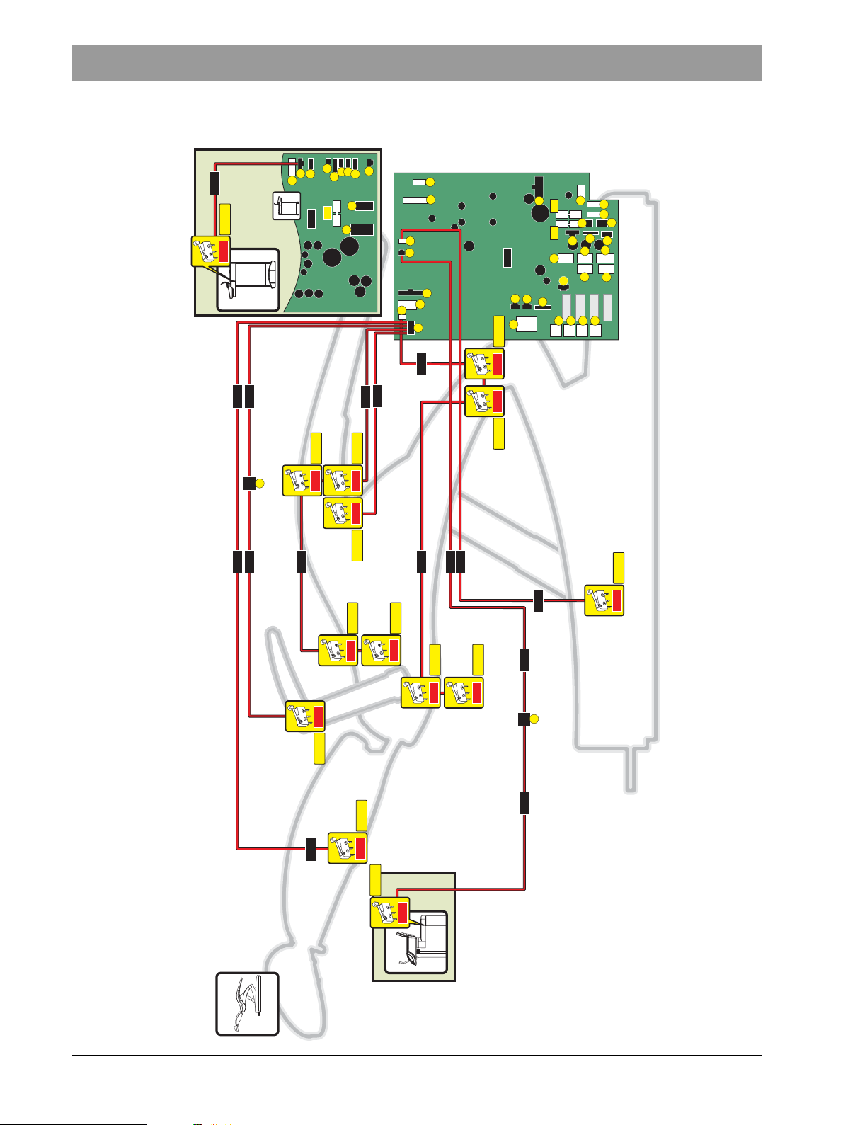
SDI
SS_MB
SS_HL
SS_HL
SS_AL
SS_RL
SS_HE
SS_HL
SS_HL
SS_HR
SS_HR
SS_HR
SS_SH
SS_HR
SS_FA
X9
X8
X14
X3
X10
X11
X13
X12
L218
S13
L332
L335
NWE
S8
1.6
Safety switches in the dental treatment center
NSA
L317
L317
L334
L331
S6
S9
S4
S1
L332
L342
L331
L332
S11
L317
L316
L333
L316
S7
S5
S12
L333L235
S3
S2
S10
S14
1 – 8 D 3509.076.01.01.02 07.2008
61 94 448 D 3509
4.
1 Important information
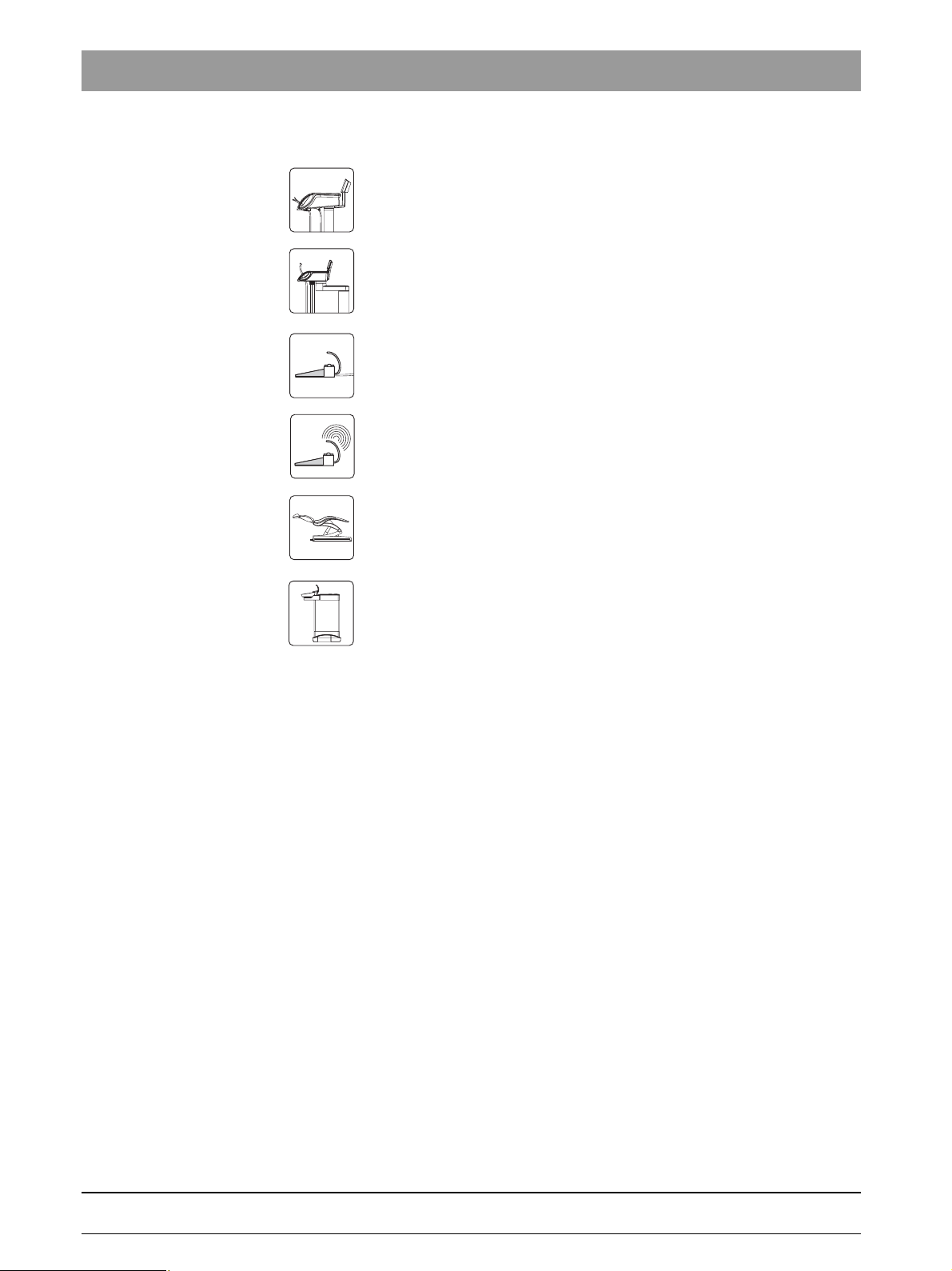
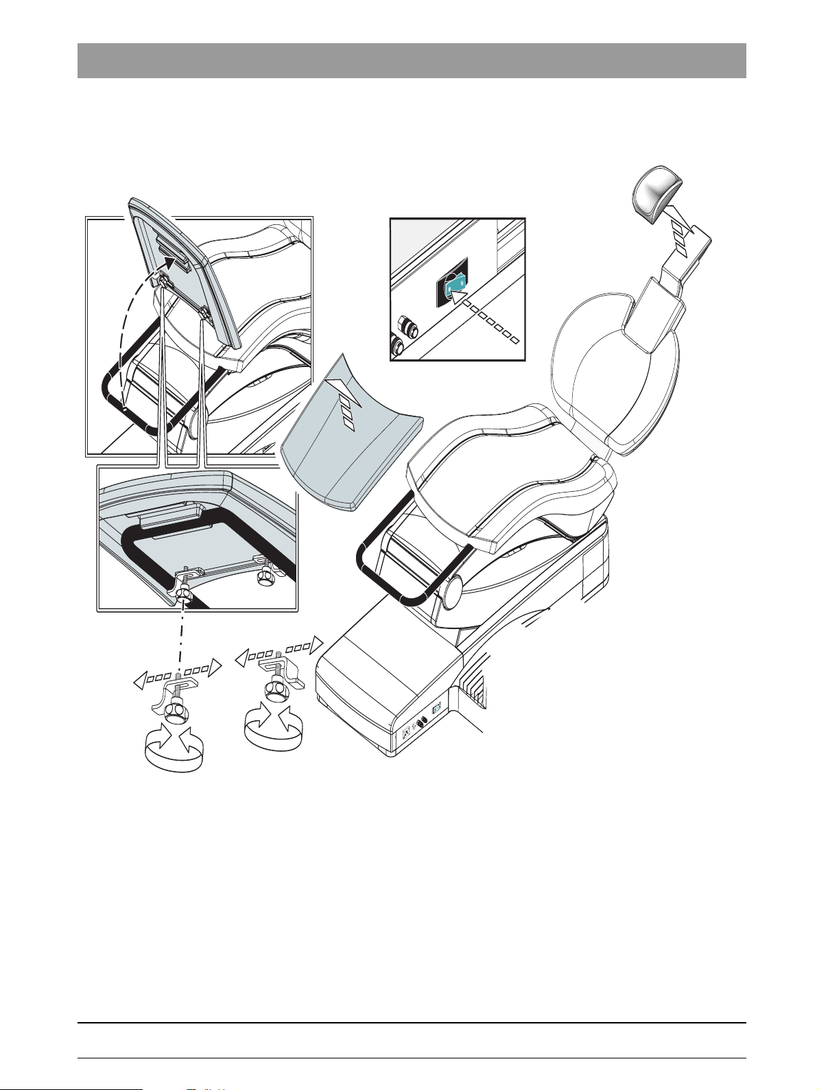
1.7 Removing the upholstery/arm rests from the patient
chair
bеЦдблЬ
2.
1.
AUS
4.
A
B
3.
B
A
1. Turn the mains power switch OFF.
2. Remove the upholstery on the headrest.
3. Loosen the screws and shift the retaining bracket B.
Remove the footrest.
4. Remove the seat upholstery.
5. Remove the backrest upholstery.
6. Pull off the backrest cover.
7. Press the release button on the armrest and pull out the armrest.
61 94 448 D 3509
D 3509.076.01.01.02 07.2008
1 – 9
1 Important information
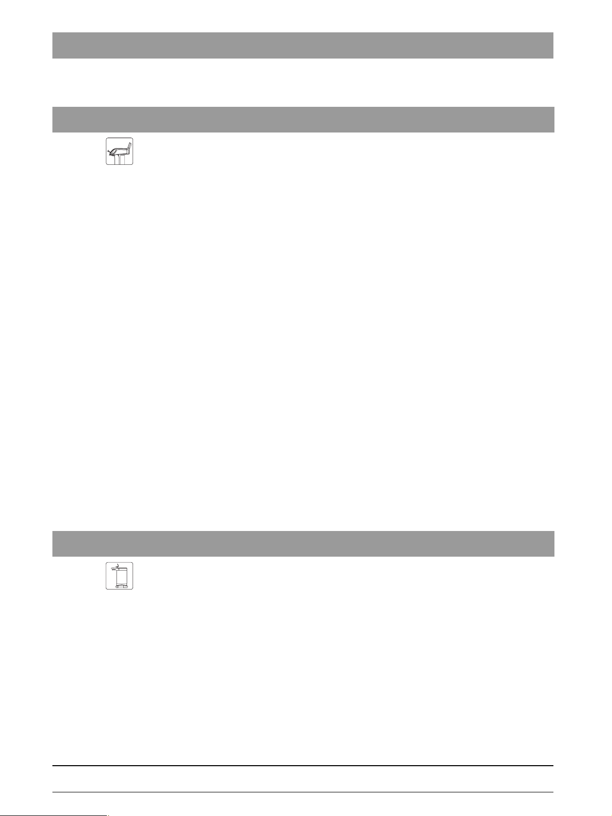
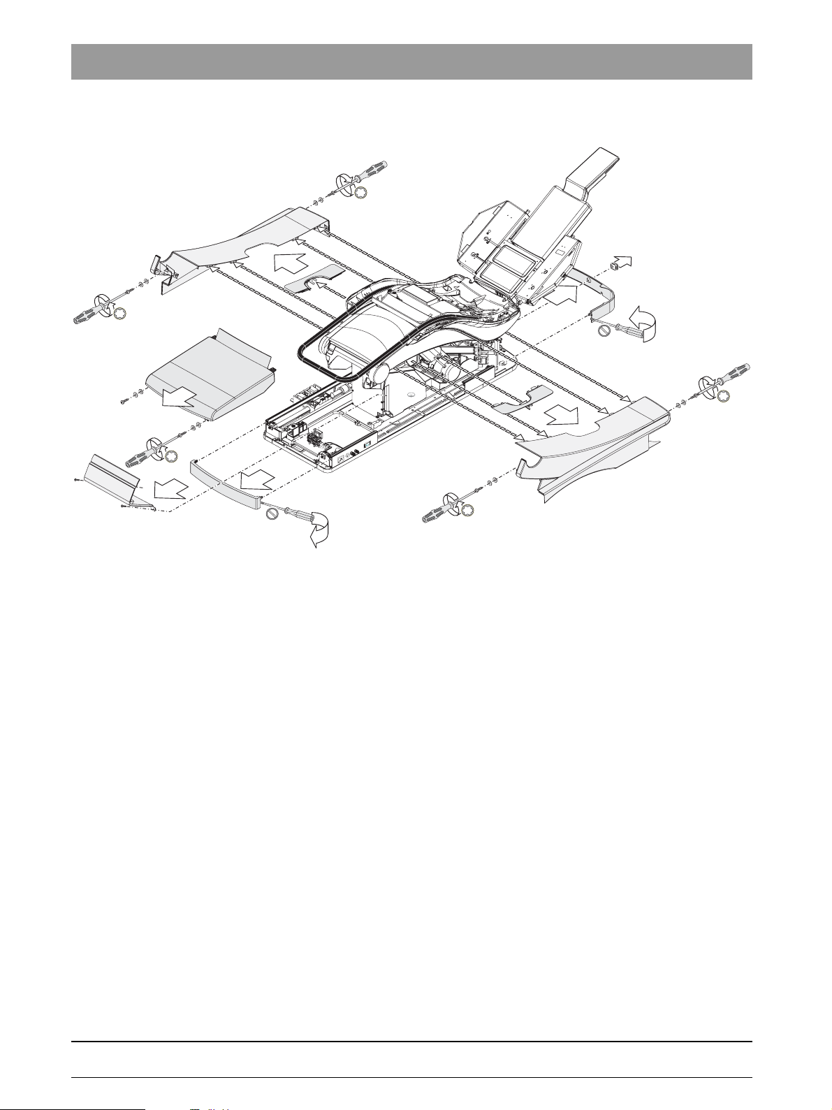
1.8
6.
6.
2.
3.
1.
7.
Removing the cover panels of the patient chair
4.
5.
6.
7.
6.
1. Remove the front faceplate of the base.
The faceplate is fitted on the lateral covers (if necessary, carefully pry
them apart with a screwdriver).
2. Unscrew the two screws (with washers) at the front of the cover.
Take off the cover.
3. Unscrew the two screws of the cover. Remove the cover (snap).
4. Pull off the small bellows from the four-way foot switch (if present).
5. Remove the rear faceplate of the base. The faceplate is fitted on the
lateral guide rails (if necessary, carefully pry them apart with a
screwdriver).
6. Remove the four screws of the side panels of the stand and remove the
covers.
7. Pull off the right and left covers.
1 – 10 D 3509.076.01.01.02 07.2008
61 94 448 D 3509
1 Important information
i
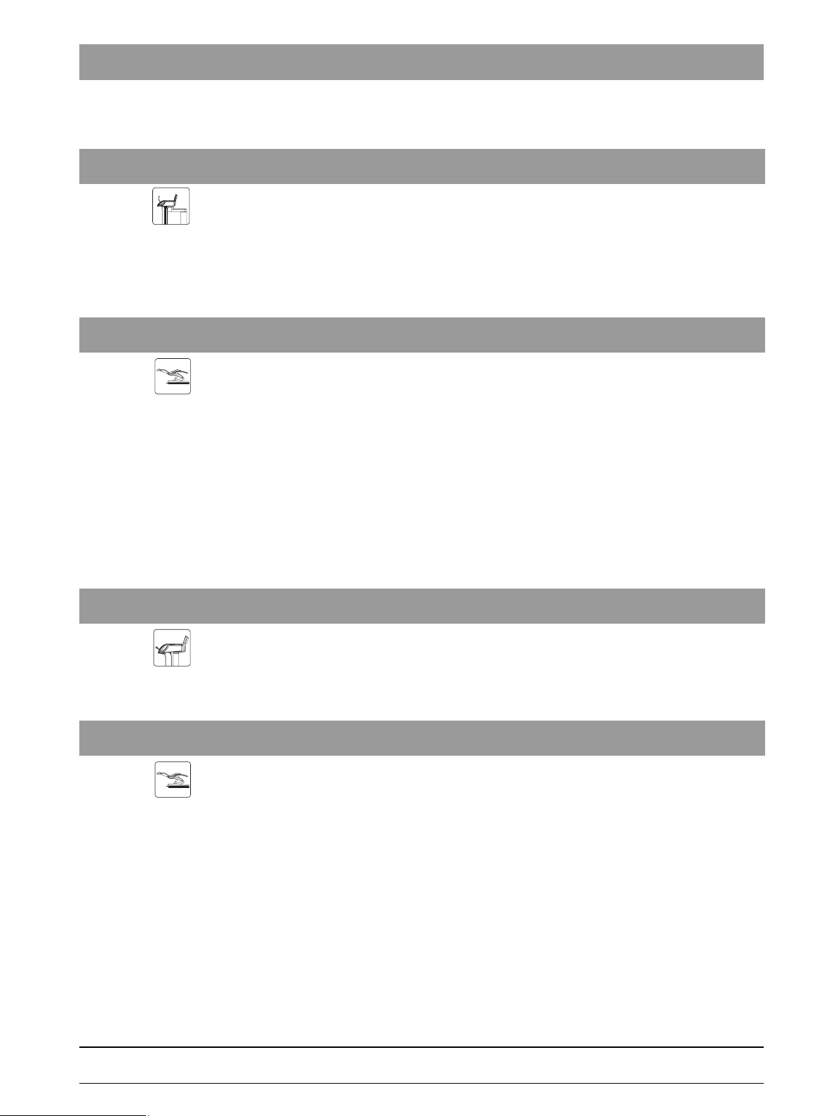
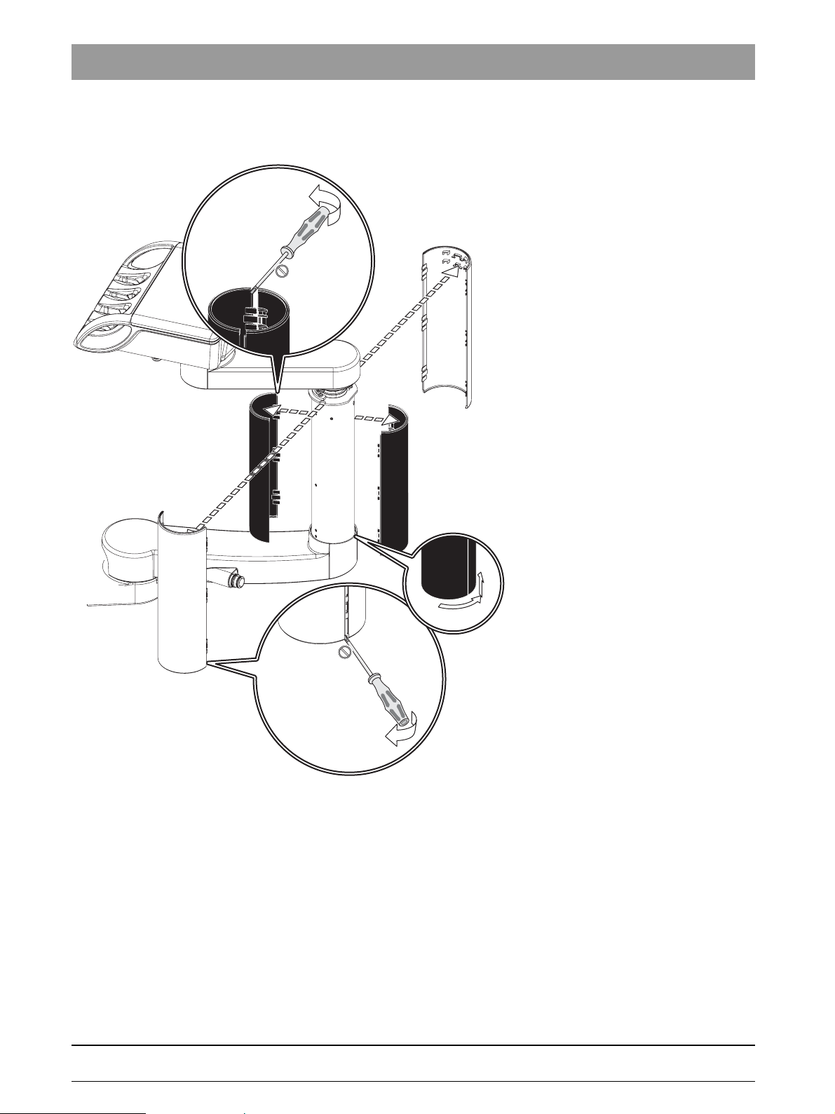
1.9 Removing the cover panels of the support arm of the
3.
1.
bеЦдблЬ
3.
1.
Dentist Element max.Assist.Element max.
3.
1.
2.
dentist element.
1. Remove the outer half-shell covers.
2. Detach the inner half-shell covers from the bayonet connector and move
them upward.
3. Remove the inner half-shell covers.
61 94 448 D 3509
D 3509.076.01.01.02 07.2008
1 – 11
1 Important information
4.
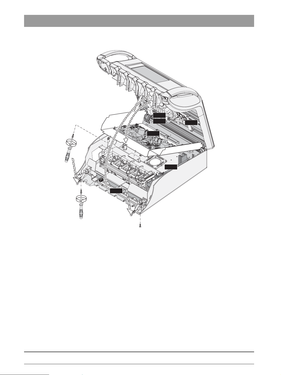
1.10
Opening the dentist element
3.
NAC
NAL
NAJ
NAU
5.
HF
2.
CC
1.
2.
1. Unscrew the two screws.
2. Press the locking bar.
3. Lift the cover upwards and let it lock it into the upright position.
4. Unscrew two screws and
5. fold down the PCB holder plate.
1 – 12 D 3509.076.01.01.02 07.2008
61 94 448 D 3509
1.
2.
2.
3.
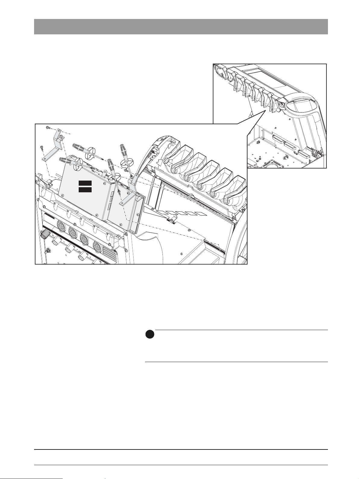
NAB
NAK
1 Important information
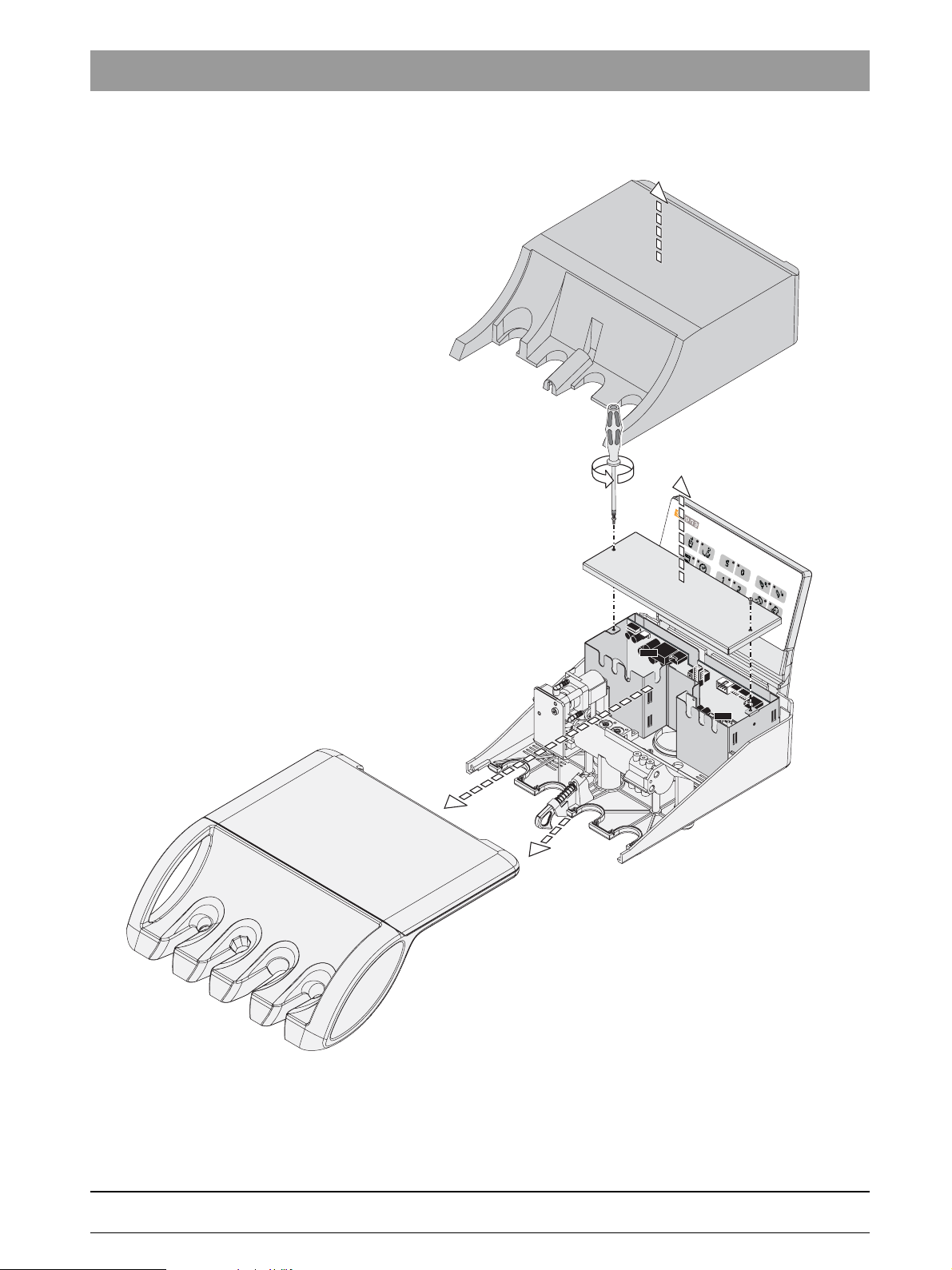
1.11 Removing the user interface on the dentist element
bеЦдблЬ
1. Loosen the setscrew.
2. Unscrew the upper screws of the retaining bracket.
Loosen the lower screws of the retaining bracket.
Turn the right retaining bracket outwards to the right and the left retaining
bracket outwards to the left.
Pull the connector X1 off of the user interface.
3. Unscrew the screw and remove the user interface panel.
i
NOTE
When re-assembling the unit:
Tighten the setscrews 1 and 3 (these are not fastening screws) only until the
user interface panel is fixed in place.
61 94 448 D 3509
D 3509.076.01.01.02 07.2008
1 – 13
1 Important information
3.
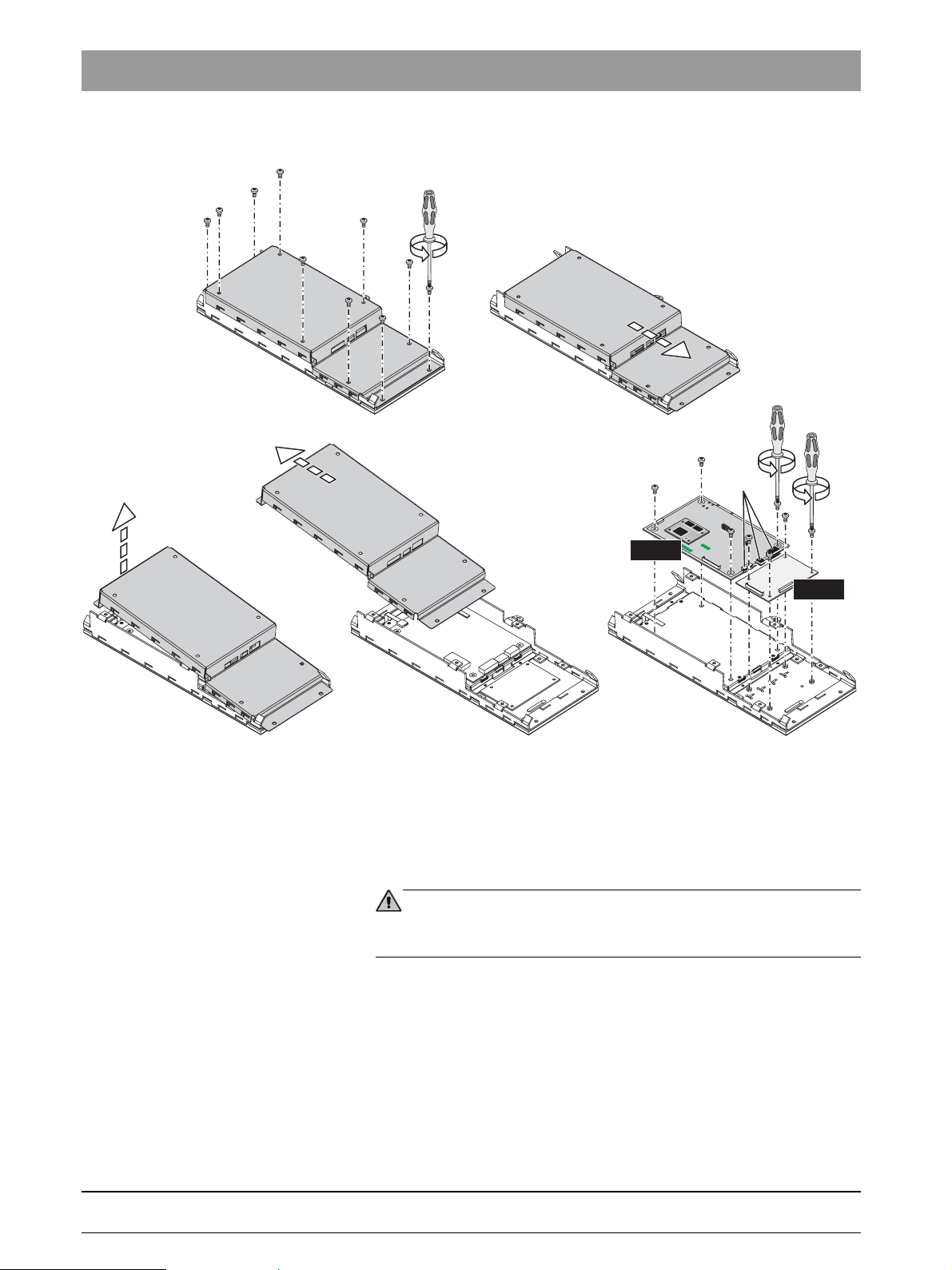
1.12
1.
Removing the NAK and NAB boards
2.
ca. 1cm
X1
X2
X3
4. 5.
NAK
NAB
1. Unscrew the ten screws.
2. Push the cover approximately 1 cm to the right.
3. Lift the left side of the cover and
4. Remove the cover diagonally to the left.
5. Unscrew the boards.
CAUTION
Pay attention to the connectors X1, X2 und X3 on the NAK board when putting
the cover back on!
61 94 448 D 3509
1 – 14 D 3509.076.01.01.02 07.2008
1 Important information
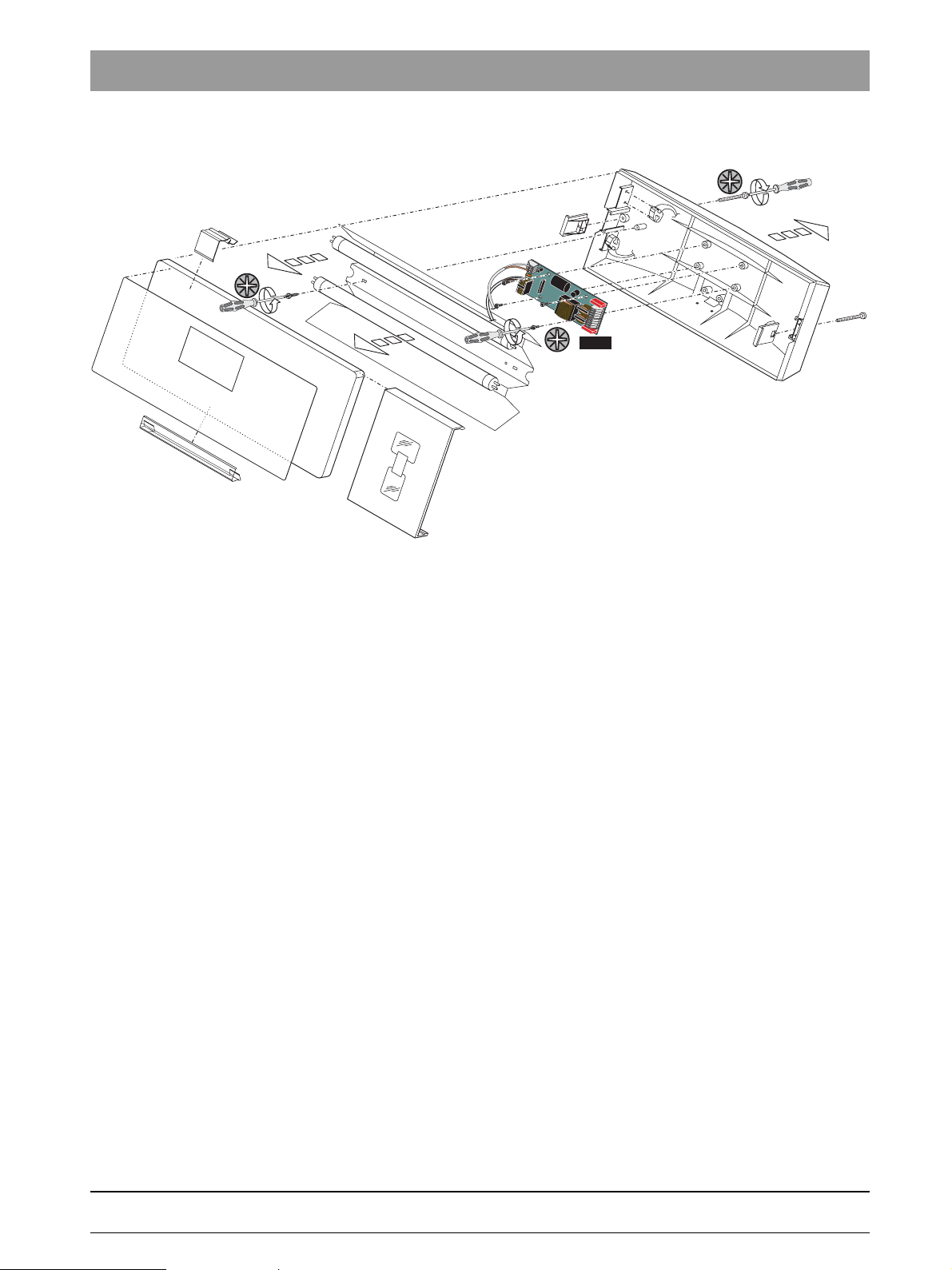
1.13 Removing the NAR board for the X-ray viewer
1.
bеЦдблЬ
3.
2.
1. Unscrew two screws and pull off the back wall.
2. Remove the fluorescent lighting tubes.
3. Unscrew two screws and take off the reflector.
4. Unscrew four screws and remove the NAR board.
4.
NAR
61 94 448 D 3509
D 3509.076.01.01.02 07.2008
1 – 15
1 Important information
3.
1.14
Removing the cover panels of the support arm of the
assistant element.
1.
3.
2.
1.
1. Remove the outer half-shell covers.
2. Detach the inner half-shell covers from the bayonet connector and move
them upward.
3. Remove the inner half-shell covers.
1 – 16 D 3509.076.01.01.02 07.2008
61 94 448 D 3509
1 Important information
1.15 Removing the cover panels of the assistant element
1.
bеЦдблЬ
1.
1.
2.
2.
C
NHE
NOP
61 94 448 D 3509
D 3509.076.01.01.02 07.2008
1. Pull the bar and remove the cover panels.
2. Unscrew two screws and remove the cover.
1 – 17
1 Important information
1.
3.
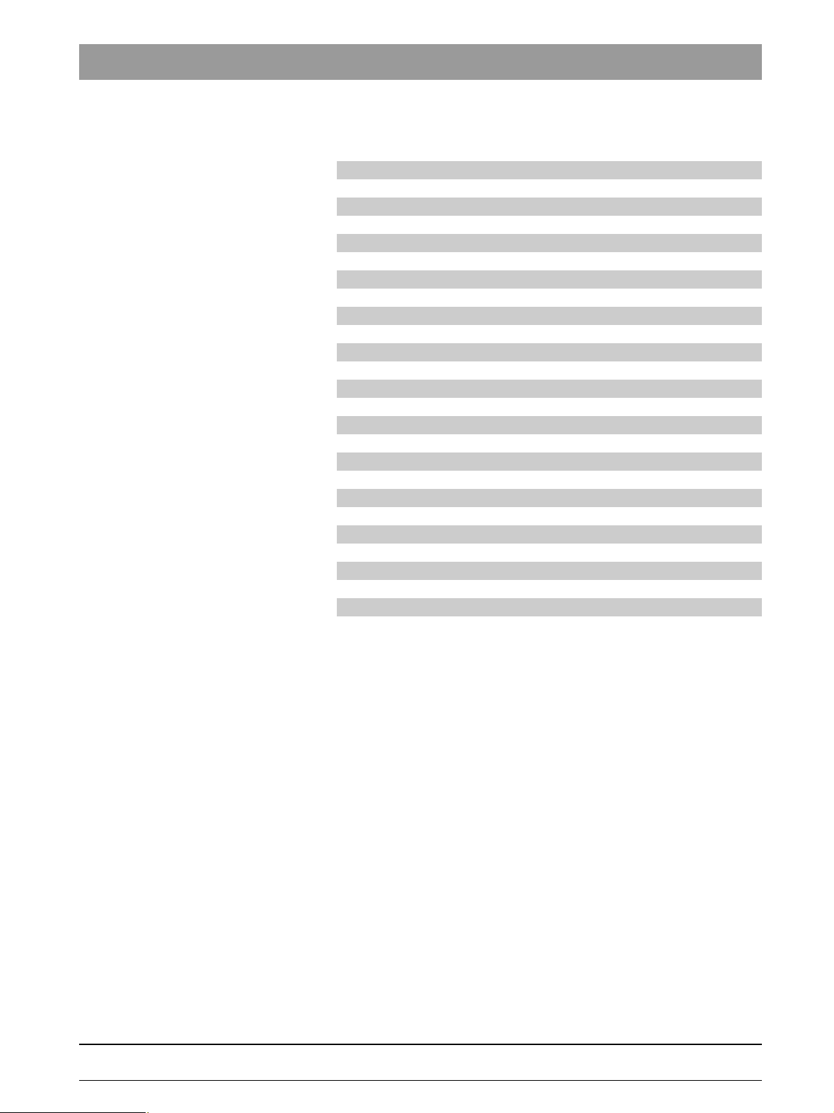
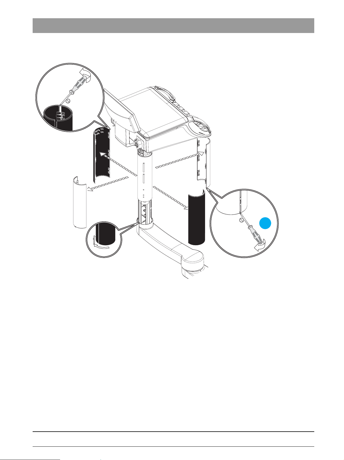
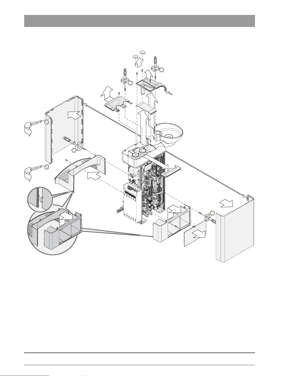
1.16
7.
Removing the cover panels from the water unit
6a.
8.
5.
A
4.
6.
3.
4
3
5
2
6
1
r
a
0
b
4
3
5
2
6
1
r
a
0
b
1.
3.
2.
1. Carefully pry apart the side panels.
Pull off the side panels.
2. Take off the service cover.
3. Unscrew the two screws on each of the covers, unhook and remove
covers.
4. Take off the cover.
5. Unscrew the four screws on the cover.
6. Remove the cover, 6a.. Remove the cover.
7. Unscrew the two screws on the cover and remove the cover.
8. Remove cover panel funnel.
Pay attention to snap-in nose A.
1 – 18 D 3509.076.01.01.02 07.2008
61 94 448 D 3509

TENEO
2 Overview of modules and boards
2.1 Locations of modules and boards
2.1
Locations of modules and boards
oder
ASEFSFU STAE WERÖBI
Component Board/module
ST Patient chair DCFU Motor control ( 3 units)
NSA Connection box
NSB Base station wireless foot control
NSC Seat connect
NSK Headrest
NSU USB connection to chair
FS Foot control
FU Wireless foot control NSF Wireless foot control
AE Dentist element CC instrument holder recognition AE (6 x)
RÖBI X-ray viewer
on the AE or tray support arm WE
ASE Assistant element NHE ASE control
WE Water unit NWE WE control
+
HF
NAB User interface AE LED board
NAC Motor control BL
NAJ AE control
NAK User interface AE baseboard
NAL Motor control SL
NAU USB connector to AE
NAR X-ray viewer board
NHT User interface ASE
NOP 5 V power supply
NWM Automatic tumbler filling
surgery module
2 – 2 D 3509.076.01.01.02 07.2008
61 94 448 D 3509
 Loading...