


C2+
Table of contents
 Loading...
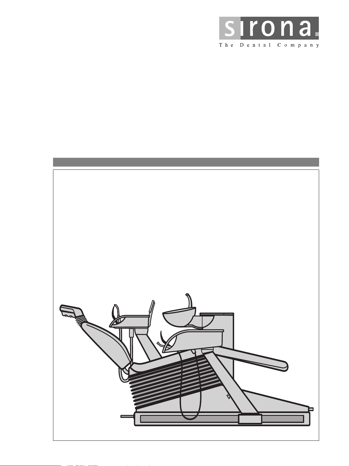
H
`O
lйЙк~нбеЦ=fелнкмЕнбзел= =
bеЦдблЬ
1 General information Sirona Dental Systems GmbH
Operating Instructions C2
1 General information
+
Dear customer, We thank you for purchasing your C2
center from the Sirona company.
The technical documentation supplied is also part of the
product. You should always keep this documentation
within reach.
These Operating Instructions describe your treatment
center with maximum possible equipment.
For daily care of your treatment center, please observe
the instructions provided in “Care and Clearing by the
Practice Team”.
To safeguard your warranty claims, please complete the
attached “Installation Report / Warranty Passport”
together with the service engineer immediately after the
installation of your treatment center.
Separate Operating Instructions with corresponding
instructions for care are enclosed with the dental
instruments, SIROLUX FANTASTIC, SIROCAM 3, tray
and X-ray image viewer.
Prior to start-up, you must read all Operating Instructions
to familiarize yourself with the treatment center.
To prevent any personal injury or material damage,
pay special attention to any notes printed in bold type or
marked in one of the ways indicated below:
+
dental treatment
i
NOTE
CAUTION
WARNING
Additional information, explanation or supplement
The information provided under this keyword directly
concerns the functioning of the product and/or warns
against possible operating errors.
This warning symbol warns against possible hazards for
the product or the user.
In case you get stuck despite having thoroughly studied
the Operating Instructions, please contact your dental
depot.
Your C2+ Team
2 D 3370.201.01.15.02
59 57 928 D 3370

Sirona Dental Systems GmbH Table of Contents
bеЦдблЬ
Operating Instructions C2
+
Table of Contents
1 General information .................................................................................................... 2
2 Warning and safety information ................................................................................ 7
2.1 General safety information................................................................................................................ 7
3 Technical description ................................................................................................. 11
4 Operating and functional elements ........................................................................... 12
4.1 System overview C2+....................................................................................................................... 12
4.2 Control panel on the dentist element................................................................................................ 13
4.3 Control panel on the assistant element ............................................................................................ 17
5 Putting the system into operation ............................................................................. 19
6 Foot switch .................................................................................................................. 21
6.1 C+ foot switch................................................................................................................................... 21
6.2 C foot switch ..................................................................................................................................... 23
7 Program selection ....................................................................................................... 25
7.1 Safety................................................................................................................................................ 25
7.2 Program selection............................................................................................................................. 26
7.3 MOVEMENT STOP! ......................................................................................................................... 27
8 Patient positions ......................................................................................................... 28
8.1 Headrest adjustable by motor drive.................................................................................................. 28
8.2 Programming Patient Positions ........................................................................................................ 29
8.3 MultiMotion headrest ........................................................................................................................ 30
9 Dentist element and instrument functions ............................................................... 33
9.1 Dentist element................................................................................................................................. 33
9.2 General instrument functions............................................................................................................ 34
9.3 Electric motor.................................................................................................................................... 35
9.4 Highspeed handpiece....................................................................................................................... 36
9.5 SIROSONIC L scaler........................................................................................................................ 37
9.6 SIROTOM HF electrosurgery ........................................................................................................... 38
9.7 SPRAYVIT ........................................................................................................................................ 39
9.8 Saving the instrument programs....................................................................................................... 39
9.9 Depositing treatment instruments..................................................................................................... 40
9.10 Surgery with saline solution (NaCl)................................................................................................... 41
9.11 Satalec Mini LED curing light............................................................................................................ 42
59 57 928 D 3370
D 3370.201.01.15.02
3

Table of Contents Sirona Dental Systems GmbH
Operating Instructions C2
10 Operation light, tumbler filling, cuspidor flushing, purge....................................... 47
10.1 Operation light.................................................................................................................................. 47
10.2 Tumbler filling function ..................................................................................................................... 47
10.3 Tumbler filling with automatic sensor control
(Special equipment, not available in all countries)........................................................................... 48
10.4 Cuspidor flushing ............................................................................................................................. 49
10.5 Purge / Auto Purge function (purging the water paths).................................................................... 50
11 Basic treatment center settings in the Mode dialog................................................ 53
11.1 Mode key ......................................................................................................................................... 53
11.2 Mode: NACL PUMP OFF or ON for instrument holder .................................................................... 53
11.3 Mode: MAINTENANCE.................................................................................................................... 54
11.4 Mode: SERVICE ONLY START - STOP.......................................................................................... 54
11.5 Mode: FC CONTROL MODE ON/OFF - VARIABLE ....................................................................... 54
11.6 Mode: TIME - HOURS : MIN............................................................................................................ 54
11.7 Mode: DAY : MON : YEAR .............................................................................................................. 55
11.8 Mode: FOOT – CONTROL NORMAL - EXTENDED ....................................................................... 55
11.9 Mode: BOWL FLUSH ON S YES - NO............................................................................................ 55
11.10 Mode: CUP FILL ON S YES - NO.................................................................................................... 55
11.11 Mode: WHITE BALANCE (only with an integrated SIROCAM 3) .................................................... 56
11.12 Instrument settings via Mode dialog: REMOVE INSTRUMENT. ..................................................... 57
11.13 Mode: # FUNCTION TOGGLE - MOMENTARY.............................................................................. 58
11.14 Mode: PURGE TIME... SEC ............................................................................................................ 58
11.15 Mode: PRESSURE PSI / BAR......................................................................................................... 58
11.16 Mode: SPRACHE / LANGUAGE ENG / D / I / F / E......................................................................... 59
11.17 Mode: SIROLUX U - POS. ON – OFF ............................................................................................. 59
11.18 Mode: POLYLUX WITH CFS YES – NO ...................................................................................... 59
11.19 Mode: SUCTION WITH CFS YES – NO......................................................................................... 59
11.20 Mode: WHITESCREEN YES – NO .................................................................................................. 60
11.21 Mode: A/B VIDEO MODE ON – OFF.............................................................................................. 60
11.22 Mode: BLOW OUT SPRAY.............................................................................................................. 60
+
12 Assistant element ....................................................................................................... 61
12.1 Suction handpieces on the assistant element.................................................................................. 61
12.2 SPRAYVIT on the assistant element ............................................................................................... 62
12.3 Satalec Mini LED curing light on the assistant element ................................................................... 62
12.4 Manual travel track........................................................................................................................... 63
13 Water unit..................................................................................................................... 64
13.1 Swiveling the cuspidor ..................................................................................................................... 64
13.2 Adjusting the water amount for the cuspidor.................................................................................... 64
13.3 Amalgam rotor ................................................................................................................................. 65
13.4 Disinfection unit (optional)................................................................................................................ 66
14 SIROTOM HF electrosurgery...................................................................................... 67
14.1 Safety............................................................................................................................................... 67
14.2 Operation ......................................................................................................................................... 68
14.3 Technical description ....................................................................................................................... 69
14.4 Technical data.................................................................................................................................. 69
14.5 Safety checks................................................................................................................................... 70
4 D 3370.201.01.15.02
59 57 928 D 3370

Sirona Dental Systems GmbH Table of Contents
bеЦдблЬ
Operating Instructions C2
+
15 SIVISION 3 .................................................................................................................... 71
15.1 System overview of SIVISION 3....................................................................................................... 71
15.2 Camera versions............................................................................................................................... 73
15.3 SIROCAM 3 intraoral camera (additional equipment) ...................................................................... 74
15.4 SIROCAM C intraoral camera (additional equipment)...................................................................... 76
15.5 Operating modes of SIVISION 3....................................................................................................... 77
15.6 SIROCAM 3 / SIROCAM C integrated in the dentist element (video) .............................................. 79
15.7 SIROCAM 3 / SIROCAM C – PC mode............................................................................................ 85
15.8 SIVISION 3–second monitor function without SIROCAM3 /SIROCAM C......................................... 89
16 CEREC Chairline (Option) .......................................................................................... 90
16.1 CEREC Chairline.............................................................................................................................. 90
17 Extra equipment and accessories ............................................................................. 91
17.1 Media block on the patient chair....................................................................................................... 91
17.2 Hygienic headrest protection ............................................................................................................ 92
17.3 Children's headrest........................................................................................................................... 92
17.4 Seat cushion C ................................................................................................................................. 93
17.5 Folding armrest................................................................................................................................. 93
17.6 Hydrocolloid coolant supply .............................................................................................................. 94
17.7 Tray (additional equipment) .............................................................................................................. 94
17.8 X-ray image viewer on the dentist element....................................................................................... 95
17.9 X-ray image viewer on the lamp support tube .................................................................................. 95
17.10 X-ray image view on the tray ............................................................................................................ 96
18 Maintenance................................................................................................................. 97
18.1 Care and cleaning by the practice team ........................................................................................... 97
18.2 Inspection and maintenance............................................................................................................. 97
18.3 Safety checks ................................................................................................................................... 98
18.4 Maintenance Manual ........................................................................................................................ 99
59 57 928 D 3370
D 3370.201.01.15.02
5

Table of Contents Sirona Dental Systems GmbH
Operating Instructions C2
+
6 D 3370.201.01.15.02
59 57 928 D 3370

Sirona Dental Systems GmbH 2 Warning and safety information
Operating Instructions C2
+
2.1 General safety information
2 Warning and safety information
2.1 General safety information
Intended use This dental treatment center is intended for diagnosis,
therapy and dental treatment of humans by properly
trained personnel.
This unit is not intended for operation in areas subject to
explosion hazards.
On-site installation The 'On-site installation' must be performed according to
our requirements. Details are described in the document
"Installation requirements".
Maintenance and repair As manufacturers of dental medical equipment and in
the interest of the operational safety of your system, we
stress the importance of having maintenance and repair
of your treatment center performed only by ourselves or
by agencies expressly authorized by us. Furthermore
components influencing the safety of the device should
always be replaced with original spare parts upon failure.
When having such work done, we suggest that you
request a certificate stating the type and extent of work
performed,
cations
range, as well as the date, name of organization and signature.
including statements concerning any modifi-
of the rated parameters or of the operating
Changes to the unit Changes to this unit which could impair the safety of the
system owner, patients or other persons are prohibited
by legislation!
For reasons of product safety, only original Sirona
accessories approved for this product, or accessories
from third parties approved by Sirona, may be used. The
user is responsible for dangers resulting from the use of
non-approved accessories.
If any devices not approved by Sirona are connected,
they must comply with the applicable standards:
IEC 60950 for information technology equipment (e.g.
PCs), and IEC 60601-1 for medical electrical equipment.
The loudspeaker socket of the monitor may be connected only to a device which complies with IEC 60950
(e.g. PC) or IEC 60601-1, and under no circumstances
e.g. to a stereo system etc.
59 57 928 D 3370
D 3370.201.01.15.02
7

2 Warning and safety information Sirona Dental Systems GmbH
2.1 General safety information Operating Instructions C2
Combination with other units Any person who assembles or modifies a medical elec-
trical system complying with the standard IEC 60601-1-1
(Safety requirements for electromedical systems) by
combining it with other equipment (e.g., by connecting it
with a PC) is responsible for ensuring that the requirements of this regulation are met to their full extent for the
safety of the patients, operators and environment.
In case of doubt, contact the manufacturer of the system
components.
+
Electromagnetic compatibility (EMC) The C2
+
complies with the requirements of
IEC 60601-1-2:2001.
Medical electrical devices are subject to special precautionary measures regarding EMC. They must be
installed and operated as specified in the document
"Installation requirements".
Portable and mobile HF communication devices can
influence medical electrical equipment. The use of
mobile telephones in the practice or hospital area therefore must be prohibited.
For video systems:
Electromagnetic disturbances in the environment of the
+
may result in reduced image quality. In such cases,
C2
it is advisable to repeat the exposure before saving the
image.
In case of line voltage fades, öimage data stored in the
video camera may be lost. Deposit the camera and
repeat the exposure.
Image artifacts may possibly occur in the event of
radio-frequency interference caused by the transmitters
of e.g. radio services or radio amateurs.
Influence on cardiac pacemakers The workstation includes strong magnets which can
affect cardiac pacemakers of patients, users and
techni-cal personnel.Therefore, please pay attention to
the safety information on pages 32 and 67.
Treatment of highly immunosuppressed patients Highly immunosuppressed patients should not come in
contact with water from the treatment center. The use of
sterile solutions is recommended.
Quality of water / air supply Air and water supply must meet the requirements speci-
fied in the Installation Instructions. Use only clean
water.
Water quality compliance To ensure compliance with the medical and national
legal requirements for water from treatment centers,
Sirona recommends equipping the treatment center with
a disinfection system. As owner of the treatment center,
you are responsible for the water quality and may have
to take alternative measures to ensure its compliance if
you operate the treatment center without a disinfection
system.
59 57 928 D 3370
8 D 3370.201.01.15.02
Sirona Dental Systems GmbH 2 Warning and safety information
Operating Instructions C2
+
Please contact your specialized dealer or your relevant
dental association for the respective national requirements and measures.
2.1 General safety information
HF surgery This dental treatment center is available with a high-fre-
quency surgical device (optional).
Only in the Federal Republic of Germany: The user is
obligated to keep a “medical product log” if a HF surgical
device is installed! See section 18.3 "Safety checks" on
page 98.
Identification of warning and safety information To avoid personal injury and material damage, you must
also observe the warning and safety information provided in the present Operating Instructions. They are
highlighted by the caption NOTE, CAUTION or
WARNING.
i
Symbols used Observe accompanying documents
(on name plate of chair)
Ventilation slots Under no circumstances may the ventilation slots on the
unit be covered, since otherwise the air circulation will be
obstructed.
Do not spray with disinfectants or the like into ventilation
slots.
Vacuum system The suction removal of aluminum and other metal oxides
from blasting devices via the automatic separator integrated in the treatment center and the amalgam separator is prohibited!
This would cause extreme wear and clogging of the suction and water paths.
A separate vacuum system must be used in connection
with metal oxide blasting devices.
Treatment centers equipped with a central wet suction
system are generally suitable for suction removal of the
above material. However, please be sure to observe the
instructions provided by the manufacturer of your vacuum system.
No restrictions apply when using salt blasting devices in
connection with Sirona treatment centers. However, in
such cases, make sure that the system is subsequently
rinsed with an adequate amount of water.
Patient chair Please observe the maximum load capacity of the chair
of 135kg according to EN ISO 6875 (tested with a
four-fold safety factor according to IEC 60601-1)
Electric micromotors in dentist element Intermittent operation: 1 min. ON – 7 min. OFF with a
motor current of 1.5A.
Drive motors for chair and backrest 6% duty time, cycle time 250s.
59 57 928 D 3370
D 3370.201.01.15.02
9
2 Warning and safety information Sirona Dental Systems GmbH
2.1 General safety information Operating Instructions C2
Maintenance of the treatment center Despite the outstanding quality of your treatment center
and regular care by the practice team, it is required in the
interest of operational safety that preventive maintenance be performed at predetermined intervals.
In order to guarantee the operational safety and reliability of your treatment center and to avoid damage
due to natural wear, you as the system owner must
have your system checked through regularly by an
authorized service engineer from your dental depot.
Furthermore, safety checks must be performed.
Please contact your dental depot to obtain a maintenance offer.
For details please refer to chapter 18"Maintenance" on
page 97.
Dismantling and reassembly When dismantling and reassembling the system, pro-
ceed according to the installation instructions for new
installation in order to guarantee its functioning and stability.
Disposal It applies generally that the national regulations have to
be complied with when disposing of this product. Please
observe the regulations applying in your country.
Within the European Economic Community the directive
2002/96/EEC (WEEE) for electrical and electronic
devices requires environmentally compatible recycling /
disposal.
+
Please observe the disposal regulations applicable in
your country.
Within the European Economic Area, this product is subject to Directive 2002/96/EC as well as the corresponding national laws. This directive requires environmentally
sound recycling/disposal of the product.
The product must not be disposed of as domestic refuse!
Please contact your dealer if final disposal of your product is required.
10 D 3370.201.01.15.02
59 57 928 D 3370
Sirona Dental Systems GmbH 3 Technical description
Operating Instructions C2
+
3 Technical description
Model designation C2
+
Power supply connection 230VAC 50Hz,
115VAC 50/60Hz
100VAC 50/60Hz
Nominal current 4.5A at 230V
9.5A at 115V
11.5A at 100V
Main unit fuse for 230VAC: SB 6.3A H , 250VAC, REF 10 77 452
for 100/115VAC: SB 10A H , 250VAC, REF 10 77 460
Operating conditions Ambient temperature: 10°C – 40°C (50°F – 104°F)
Relative humidity: 30% – 75%
Air pressure: 700hPa – 1060hPa
Transport and storage conditions Temperature: -40°C – +70°C (-40°F – 158°F)
Relative humidity: 10% – 95%
Air pressure: 500hPa – 1060hPa
Protection class Class I equipment
Degree of protection against electrical shock: Type B, applied parts
except Cerec 3D camera, SIROTOM, SIROCAM 3 /
SIROCAM C:
Type BF applied parts
Degree of protection against ingress of water Ordinary equipment (not protected)
The foot switch is protected against dripping water IPX
1.
Mode of operation: Continuous operation with intermittent loading corre-
sponding to the dental mode of working.
Permanently connected unit.
Year of manufacture (on name plate of chair)
Tests / approvals This dental treatment center complies with the require-
ments of
IEC 60601-1: 1988 + A1: 1991 + A2: 1995 and of
IEC 60601-1-2: 2001 .
DVGW: This unit complies with the technical rules and
requirements on safety and hygiene for connection to
the drinking water supply, provided that a disinfection
unit is installed.
This product bears the CE marking in accordance with
the provisions of the Council Directive 93/42/EEC of
June 14, 1993 concerning medical devices.
0123
59 57 928 D 3370
D 3370.201.01.15.02
11
4 Operating and functional elements Sirona Dental Systems GmbH
S
0
4.1 System overview C2
+
Operating Instructions C2
4 Operating and functional elements
+
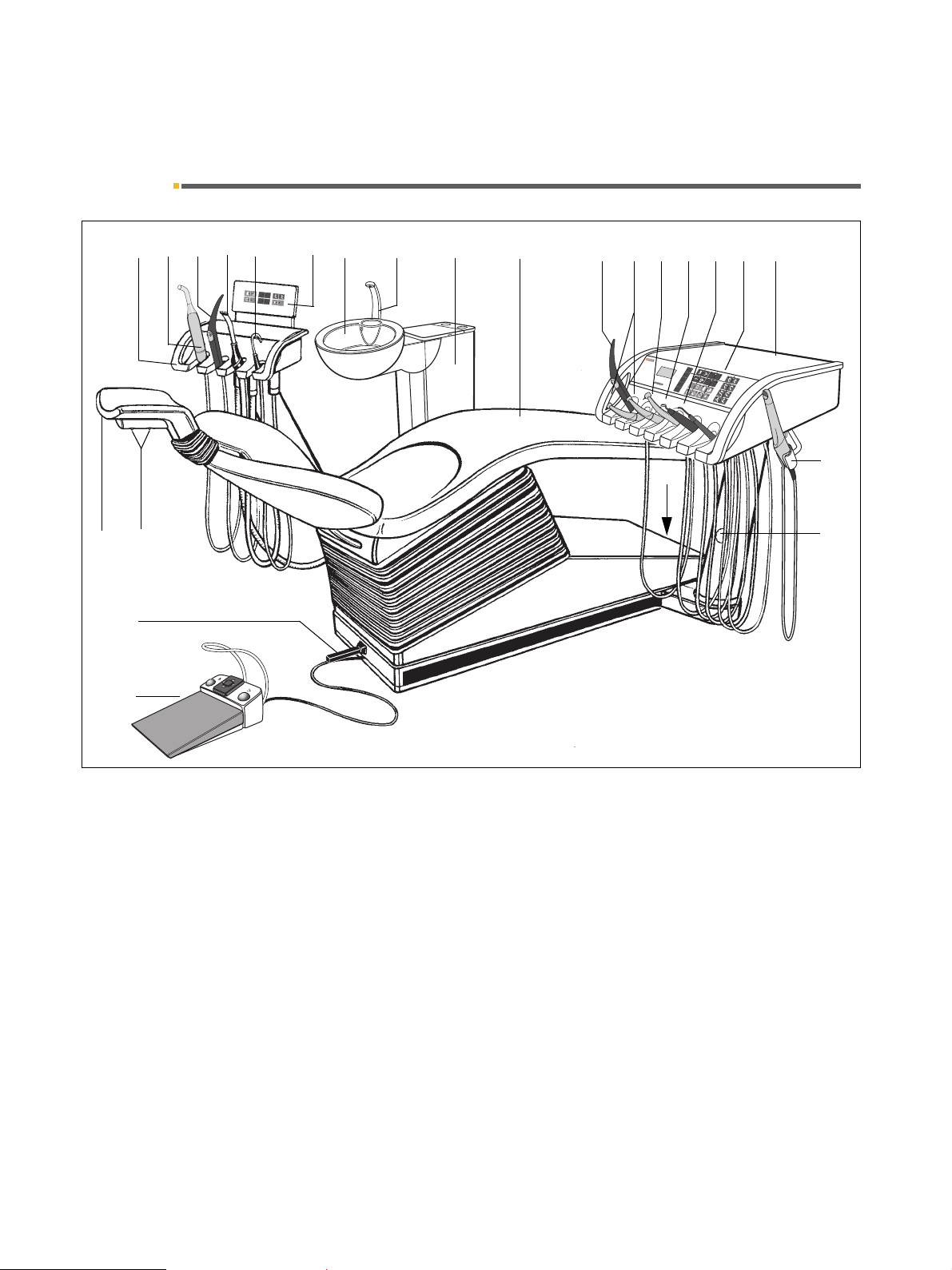
4.1 System overview C2
20
1
21
22
234
56
S
0
SAN
1
2
L
7
+
8
910
11 12 13 14 16 1715
+
C2
4
0
1
0
0
3
0
7
5
SS
2
0
5
0
–
M
ode
11
1
0
+
22
2
2
5
5
A
/
B
0
.2
r
p
m
x
1
1
0
0
0
00
24
18
19
23
1
Assistant element
2
Holder 1: Polylight Mini LED or 3rd suction hose
3
Holder 2: SPRAYVIT in the assistant element
4
Holder 3: Suction handpiece
5
Holder 4: Saliva ejector
6
Control panel on the assistant element
7
Swiveling cuspidor
8
Tu m bl er f il le r
9
Water unit with amalgam rotor, disinfection system,
automatic separator, wet suction
10
Patient chair, option: folding armrest
11
Holder 1: SPRAYVIT in the dentist element
12
Holder 2 and 3: Electric motor / highspeed handpiece burr drives
13
Holder 4: 3. Electric motor / highspeed handpiece
burr drive or SIROSONIC L scaler
14
Holder 5: 4. Burr drive (highspeed handpiece only)
or SIROSONIC L
or Polylight Mini LED
15
Holder 6: SIROSONIC L or HF surgery
or SIROCAM 3 / SIROCAM C
or Polylight Mini LED
16
Control panel on the dentist element
17
Dentist element
18
Unit main switch
19
Locking brake on the dentist and assistant element
20
Headrest adjustable by motor drive
21
Manual switch for chair movements
22
4-way foot control of chair
23
unit foot switch
24
Additional holder (for SIROCAM 3 / SIROCAM C
only)
59 57 928 D 3370
12 D 3370.201.01.15.02
Sirona Dental Systems GmbH 4 Operating and functional elements
AMALG
DESINF
Operating Instructions C2
+
4.2 Control panel on the dentist element
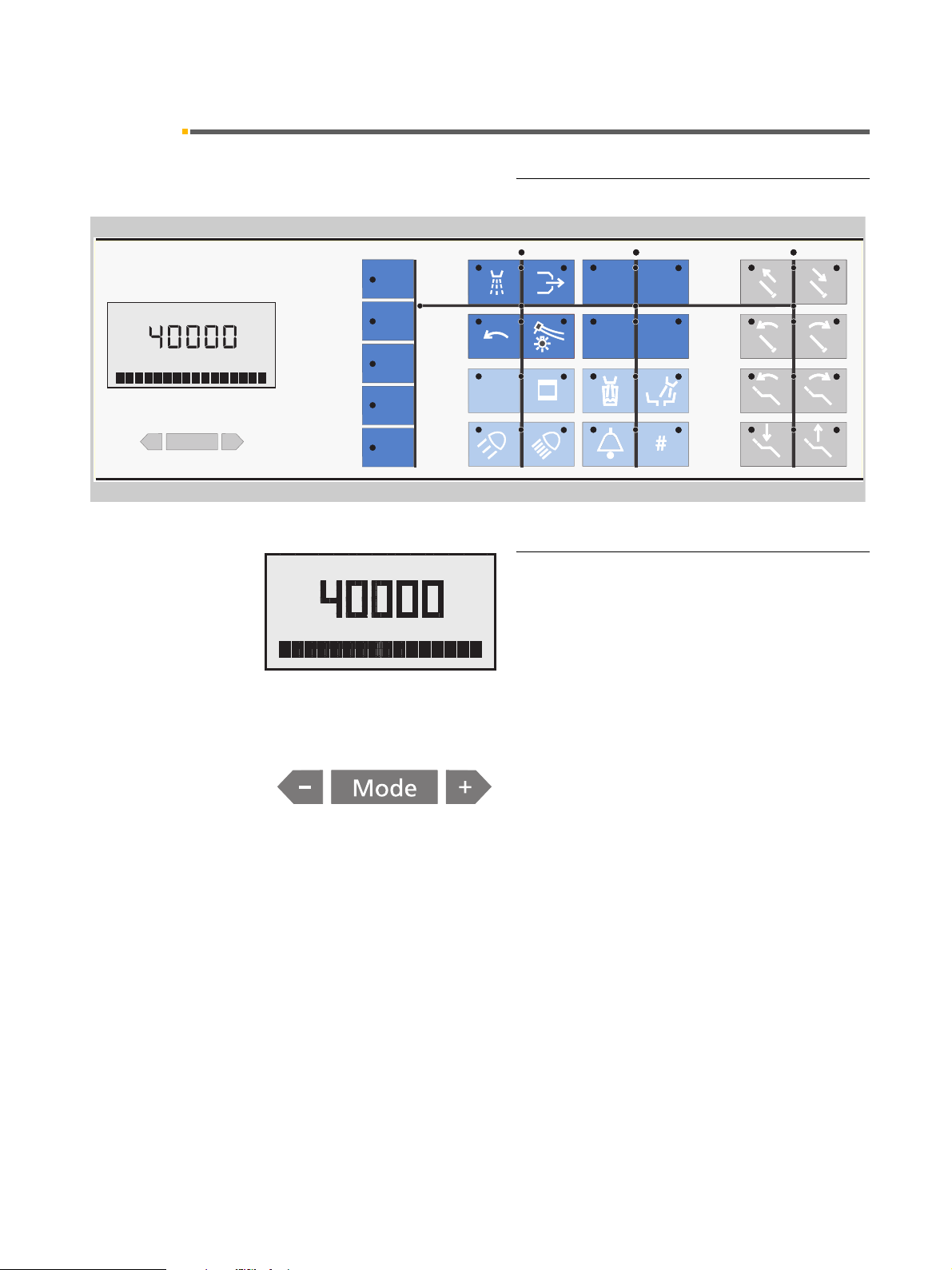
4.2 Control panel on the dentist element
Control panel
40
100
SS
00
A
RPM
30
20
75
50
11
22
A/B
10
25
–
–
Mode
+
0.2
rpm x 1000
AMALG
1
DESINFAB
RPM
System status indication display and Mode
key
AMALG appears if the amalgam rotor needs to be
replaced.
DESINF flashes if DENTOSEPT P must be refilled.
A appears if user A is selected.
B appears if user B is selected.
Mode button with
tings.
Apart from the settings in the Mode dialog, it is also possible to make settings with the
• Intensity of instrument lighting
• Intensity of the operation light
• Tumbler filling time
• Cuspidor flushing time
+ / – keys for programming basic set-
+ / – keys:
59 57 928 D 3370
D 3370.201.01.15.02
13
4 Operating and functional elements Sirona Dental Systems GmbH
4.2 Control panel on the dentist element Operating Instructions C2
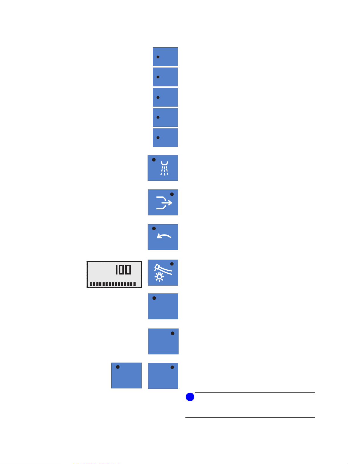
Main functions – dark blue keys
40
40
100
100
Quick setting keys for instrument intensity and
speed
+
30
20
10
0.2
rpm x 1000
75
50
25
1
for electric motors, SIROSON L ultrasound scalers and
SIROTOM HF electrosurgery.
Spray ON / OFF
on burr drives
Chip blower
on burr drives
Counterclockwise rotation
for electric motor
A
INSTR. LIGHT
11
Instrument light ON / OFF
%
SS
Pressing this key for some time displays the light intensity settings dialog.
Mouth rinsing position chair program.
with last position memory function (freely programmable)
Chair program 0
Entry/exit position (freely programmable)
00
Chair programs 1 and 2
(freely programmable)
22
i
NOTICE
The four program keys are also used for reprogramming
the chair programs.
14 D 3370.201.01.15.02
59 57 928 D 3370

Sirona Dental Systems GmbH 4 Operating and functional elements
Operating Instructions C2
+
4.2 Control panel on the dentist element
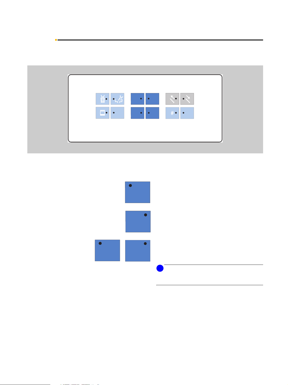
Additional functions – light blue keys
Preselection of user A or B
A
OPERATING LIGHT
A/B
All instruments must be in place.
The user cannot be changed as long as one of the instruments is removed
.
Saving the instrument settings
The instrument to be programmed must be removed.
X-ray image viewer ON/OFF
For SIVISION 3 also WHITE SCREEN activation
Composite key ON / OFF
for SIROLUX operation light, reduced light intensity
8,000 lux for composite fillings
<
SIROLUX operation light ON / OFF
%
for normal light intensity > 24,000 lux
Pressing this key for a while displays the light intensity
settings dialog:
OPERATING LIGHT
A
CUP FILL TIMER
A
BOWL FLUSH TIMER
Tumbler filling
Pressing this key for a while displays the settings dialog:
CUP FILL TIMER
Cuspidor flushing
Pressing this key for a while displays the settings dialog:
BOWL FLUSH TIMER
Freely selectable function
e.g. call key, always functions as button
freely available relay 230 V, 6 A
(connected by the service engineer).
Freely selectable function
The function can be preselected in the Mode dialog as
button or switch.
freely available relay 230V, 6 A
(connected by the service engineer).
59 57 928 D 3370
D 3370.201.01.15.02
15
4 Operating and functional elements Sirona Dental Systems GmbH
4.2 Control panel on the dentist element Operating Instructions C2
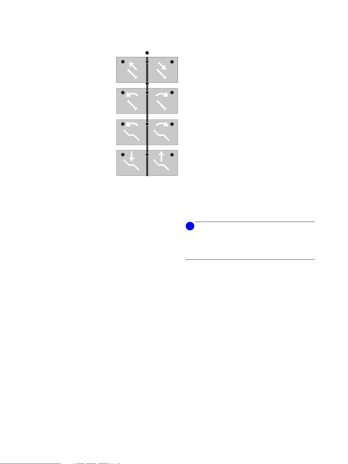
Chair functions – gray keys
for manual chair settings:
Move headrest out / in
(cannot be used with MultiMotion head rest)
Tilt headrest backward or forward.
(cannot be used with MultiMotion head rest)
Tilt backrest backward or forward.
Vertical adjustment down / up
+
Additional functions of the panel keys
for video
i
NOTICE
Apart from the previously described functions, the keys
of the dentist element have additional functions in connection with the video application. These are described
in chapter 15 starting on page 71.
16 D 3370.201.01.15.02
59 57 928 D 3370
Sirona Dental Systems GmbH 4 Operating and functional elements
Operating Instructions C2
+
4.3 Control panel on the assistant element
4.3 Control panel on the assistant element
Control panel
SAN
S
1
00
SS
0
2
Main functions – dark blue keys
Mouth rinsing position chair program.
with memory function (freely programmable)
Chair program 0
Entry/exit position (freely programmable)
L
59 57 928 D 3370
D 3370.201.01.15.02
11
22
Chair programs 1 and 2
(freely programmable)
i
NOTICE
The four program keys are also used for reprogramming
the chair programs.
17
4 Operating and functional elements Sirona Dental Systems GmbH
4.3 Control panel on the assistant element Operating Instructions C2
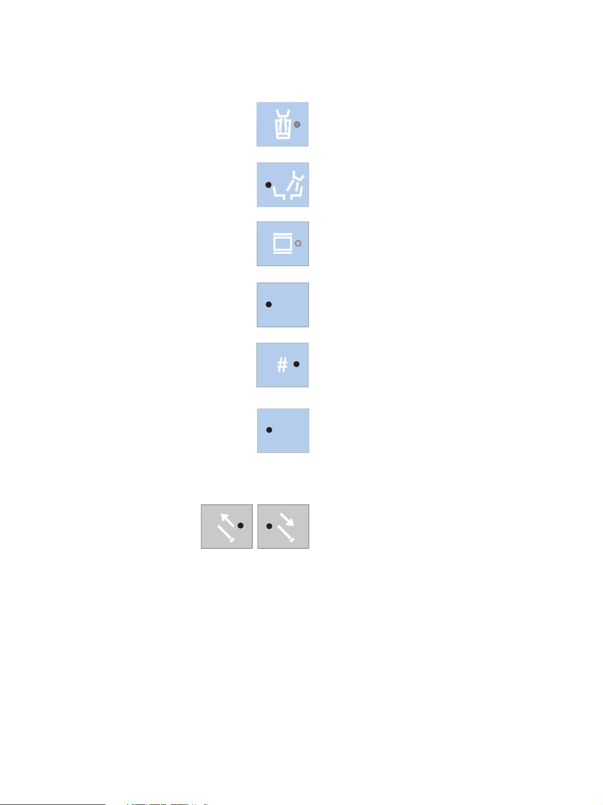
Additional functions – light blue keys
Tumbler filling function
ON / OFF
Cuspidor flushing function
ON / OFF
X-ray image viewer ON / OFF
for SIVISION 2 also WHITE SCREEN activation
Sanitation of the treatment center
+
SAN
L
This key can be used to start the treatment center sanitation program (see instructions “Care and Cleaning by
the Practice Team”).
Freely selectable function
The function can be preselected in the Mode dialog as
button or switch.
Light ON/OFF
With SPRAYVIT removed:
• Instrument lighting
With SPRAYVIT deposited:
• Operation light
Chair functions – gray keys
Manual adjustment of headrest
Move headrest out/in
(cannot be used with MultiMotion head rest)
18 D 3370.201.01.15.02
59 57 928 D 3370
Sirona Dental Systems GmbH 5 Putting the system into operation
Operating Instructions C2
+
5 Putting the system into operation
Initial start-up
The disinfection system adds a disinfectant to the water
(1:100) to prevent the formation of microorganisms in
the water system.
Prior to initial start-up of your treatment center, sanitation must be performed.
If, on the basis of an agreement with you, sanitation
was skipped by the service engineer following installation of your treatment center, please perform sanitation
yourself as described in the separate instructions “Care
and Cleaning by the Practice Team”.
Sanitation takes approx. 24 hours.
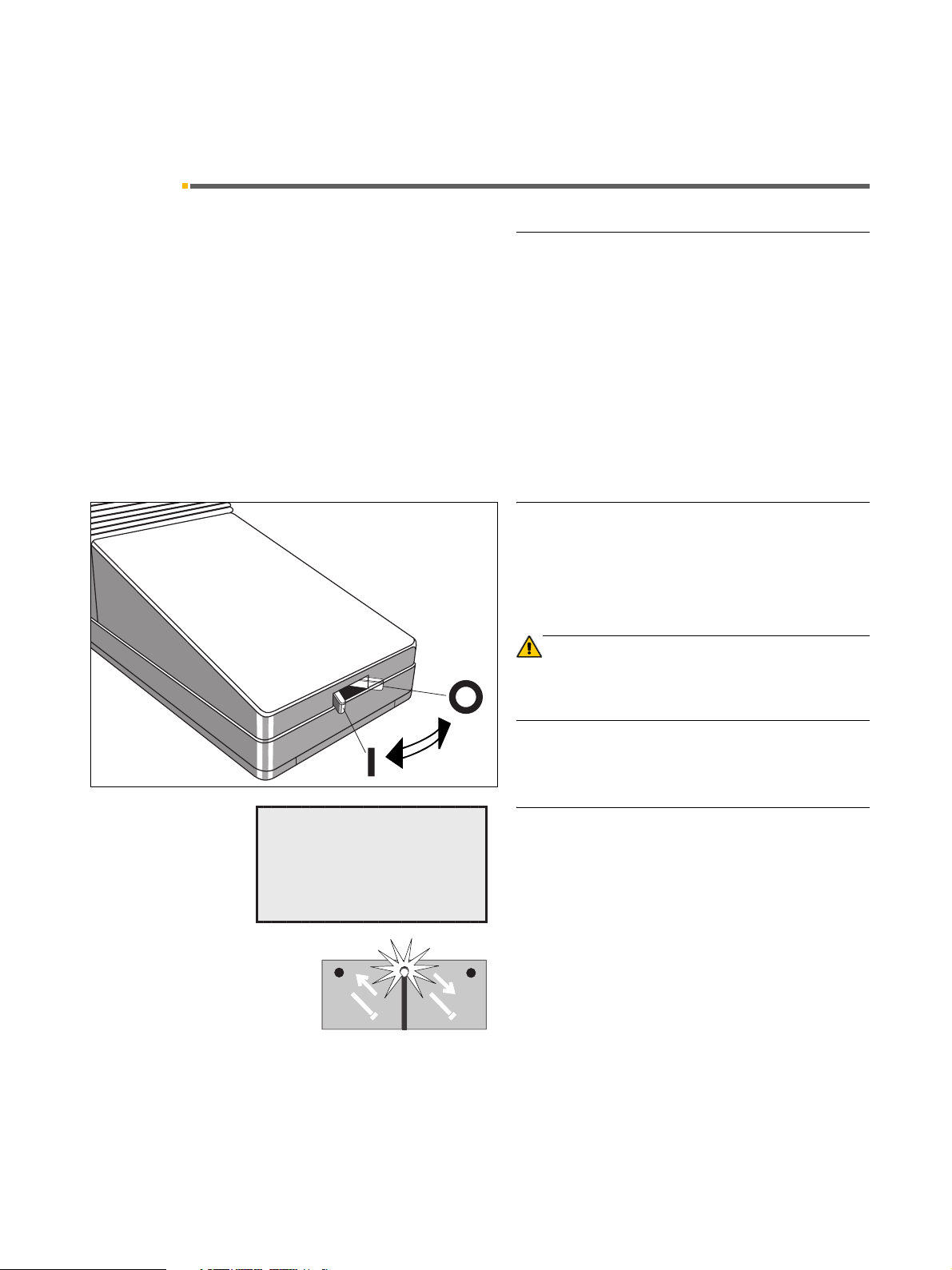
Main switch
A
READY
10:04:27
ON
OFF
Switch the main switch ON ( l ).
Following power-up, the treatment center automatically
performs a self-test.
CAUTION
For safety reasons, always switch the treatment center
OFF (O) after consulting hours. This cuts off the air and
water supply and the line voltage.
Ready to operate
After the end of the self-test, the message READY the
time and the last selected user, A or B, appear on the
display.
After the treatment center has been switched on, the
cursor is between the headrest in/out keys.
If a program LED lights up, then the chair was in a programmed position before the treatment center was
switched off. If no program LED lights up, then the chair
was in a non-programmed position before the treatment
center was switched off.
59 57 928 D 3370
D 3370.201.01.15.02
The unit is now ready to operate.
19
5 Putting the system into operation Sirona Dental Systems GmbH
A
MAINTENANCE
IN 30 DAYS
Operating Instructions C2
Display of next maintenance date
the next maintenance date is less than 30 days away,
this message appears each time the unit is switched on.
MAINTENANCE
IN 30 DAYS
(see MAINTENANCE Mode dialog).
After this date has expired, the following message is displayed:
MAINTENANCE
REQUIRED
The display message then disappears as soon as an
instrument is removed from its holder.
i
NOTICE
This message can be reset only by the service technician after completion of maintenance work.
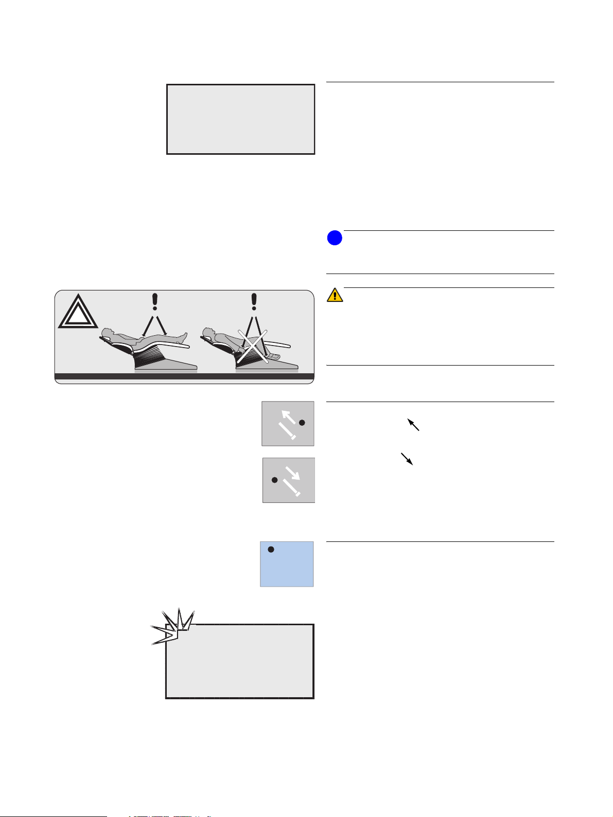
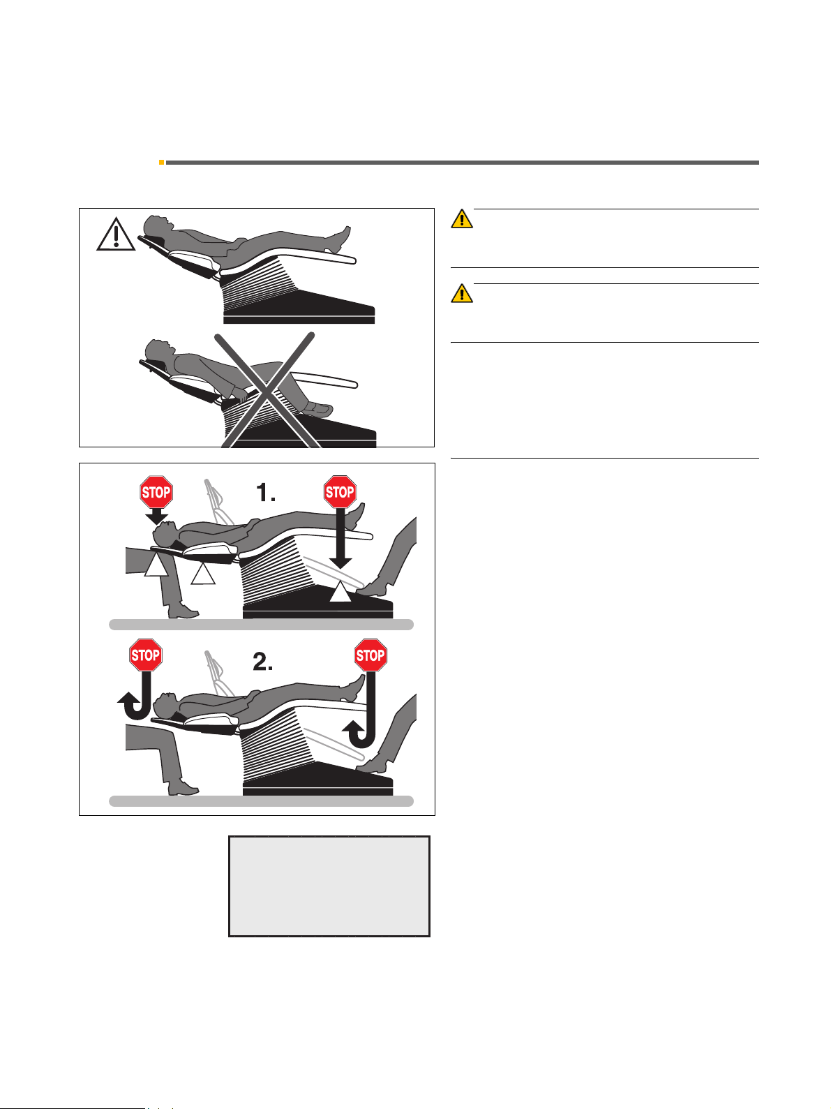
CAUTION
wrongright
The dental chair has a maximum load capacity of 135kg
according to EN ISO 6875 (tested with a four-fold safety
factor according to IEC 60601-1).
The patient’s arms and legs must rest on the upholstery
of the chair!
+
A
B
READY
10:04:27
A/B
Adjusting the headrest
Move headrest out
Move headrest in
Hygienic headrest protection and seat cushion for children: see page 93.
Preselecting the user
The treatment center offers the possibility of managing
two different chair and instrument programs for two
users.
Preselect user A or B using the A/B key, with all instruments in place.
The preselected user is shown in the top left corner of
the display. All settings which have been stored for that
user are then activated.
20 D 3370.201.01.15.02
59 57 928 D 3370
Sirona Dental Systems GmbH 6 Foot switch
Operating Instructions C2
+
6.1 C+ foot switch
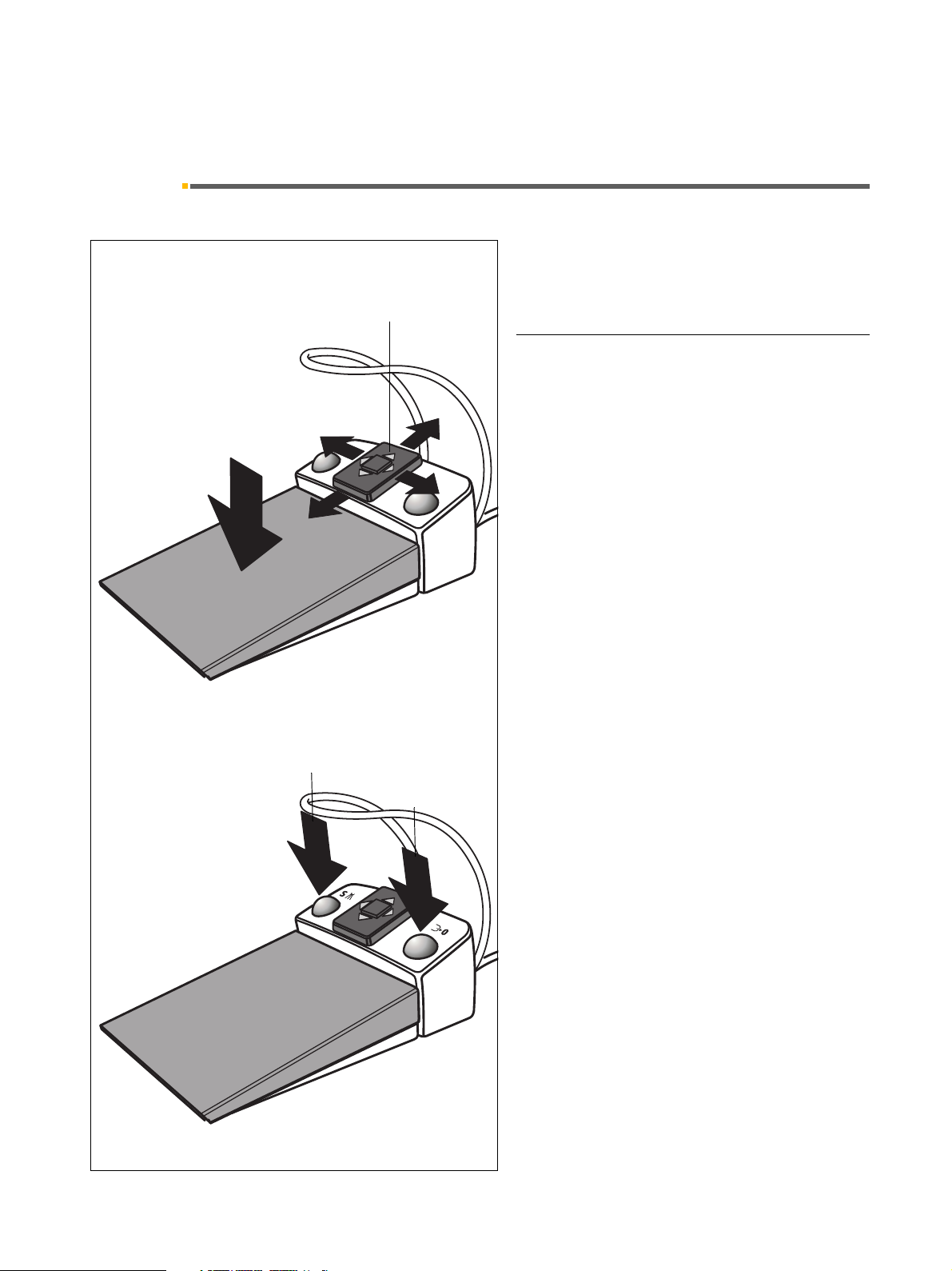
6 Foot switch
6.1 C
+
foot switch
1.
B
C
3.
2.
4.
A
D
This foot switch allows you to work with both hands free
using the cursor control or manually by key operation.
The foot switch has a 4-way foot control plate for cursor
navigation, which works independently of the pedal.
Functions
1. Step on foot pedal – all instruments in place
The dentist element moves toward the operator as
long as the foot switch is actuated
(or toward the foot end of the patient if reversed by
the service engineer, see page 28).
Step on foot pedal – instrument removed
Activation of the instrument.
If appropriate, intensity control relative to pedal
movement (if “speed controller foot switch” has been
preset under Mode).
2. Shift 4-way foot control plate
With cursor control enabled
(Mode dialog 11.8):
A forward – cursor up
B backward – cursor down
C to the left – cursor to the left
D to the right – cursor to the right
Cursor navigation along the marked path and re-
lease of the corresponding key function.
With cursor control disabled
(Mode dialog 11.8):
A forward – without function
B backward – the dentist element moves away as
long as the switch is actuated by the user.
C to the left – without function
D to the right – without function
59 57 928 D 3370
D 3370.201.01.15.02
3. Actuate left button – all instruments in place
Programmed movement of the chair into mouth rins-
ing position S or into last treatment position (accord-
ing to starting situation).
Actuate left button – instrument removed
Toggle between spray ON and spray OFF, or
SIVISION function.
4. Actuate right button – all instruments in place
Programmed movement of the chair into the entry/
exit position 0.
Actuate right button – instrument removed
Chip blower active for duration of actuation, or
SIVISION function.
21
6 Foot switch Sirona Dental Systems GmbH
6.1 C+ foot switch Operating Instructions C2
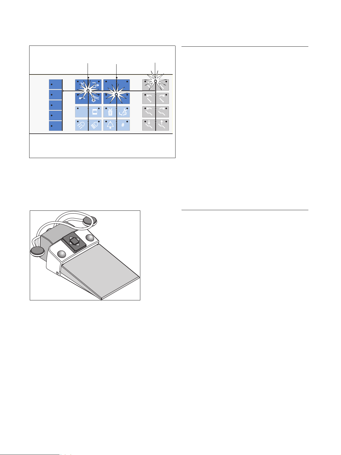
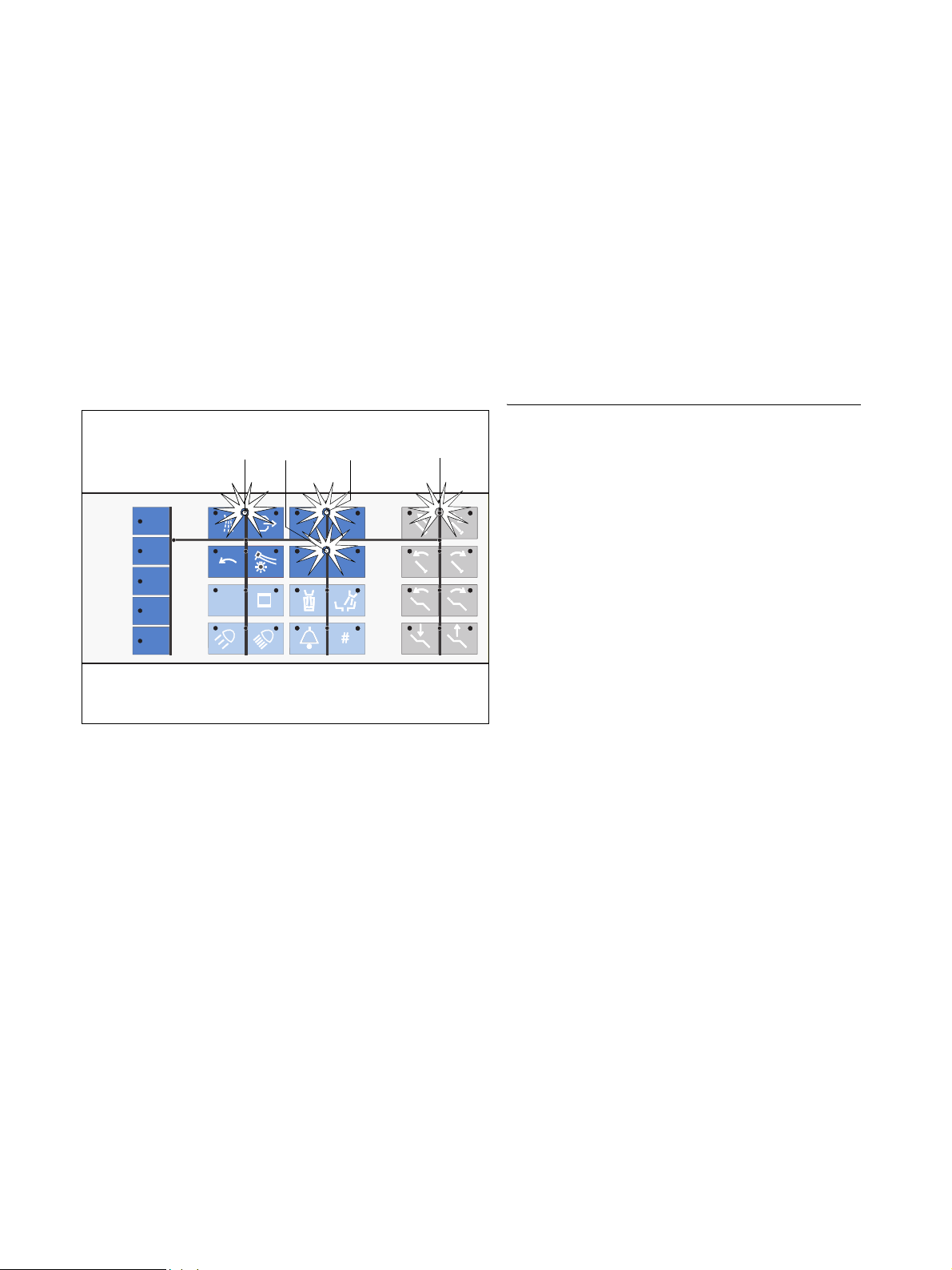
Automatic cursor control with C+ foot switch
1.
A yellow diode on the dentist element indicates the position of the cursor. The cursor path is marked by lines.
1. After the unit is switched on or after the entry/exit position 0 has been reached, the cursor is between the
move headrest out / in keys in the right key block.
To simplify hand-free headrest positioning, the cursor again jumps between the move headrest out / in
keys if the instruments are removed only for wipe
disinfection or for changing straight/contra-angle
handpieces, but are not activated.
2. After the dentist element is moved via the foot switch
pedal, the cursor jumps between chair program keys
1 and 2.
3. On instrument removal or on activation of any instru-
ment, the cursor jumps to the horizontal navigation
path (position between 1st and 2nd row of keys) in
the instrument block.
4. After the instrument is deposited the cursor jumps
back to its position between chair program keys 1
and 2.
0.2
rpm x 1000
3.
40
100
30
75
20
50
10
25
1
A/B
2./4.
SS1100
22
+
CEREC Chairline foot switch
This foot switch includes all of the functions of the
+
foot switch.
C
It also features an additional pedal for operation of the
CEREC Chairline.
For details please refer to the CEREC Chairline Operating Instructions, REF 60 46 028.
22 D 3370.201.01.15.02
59 57 928 D 3370
Sirona Dental Systems GmbH 6 Foot switch
Operating Instructions C2
+
6.2 C foot switch
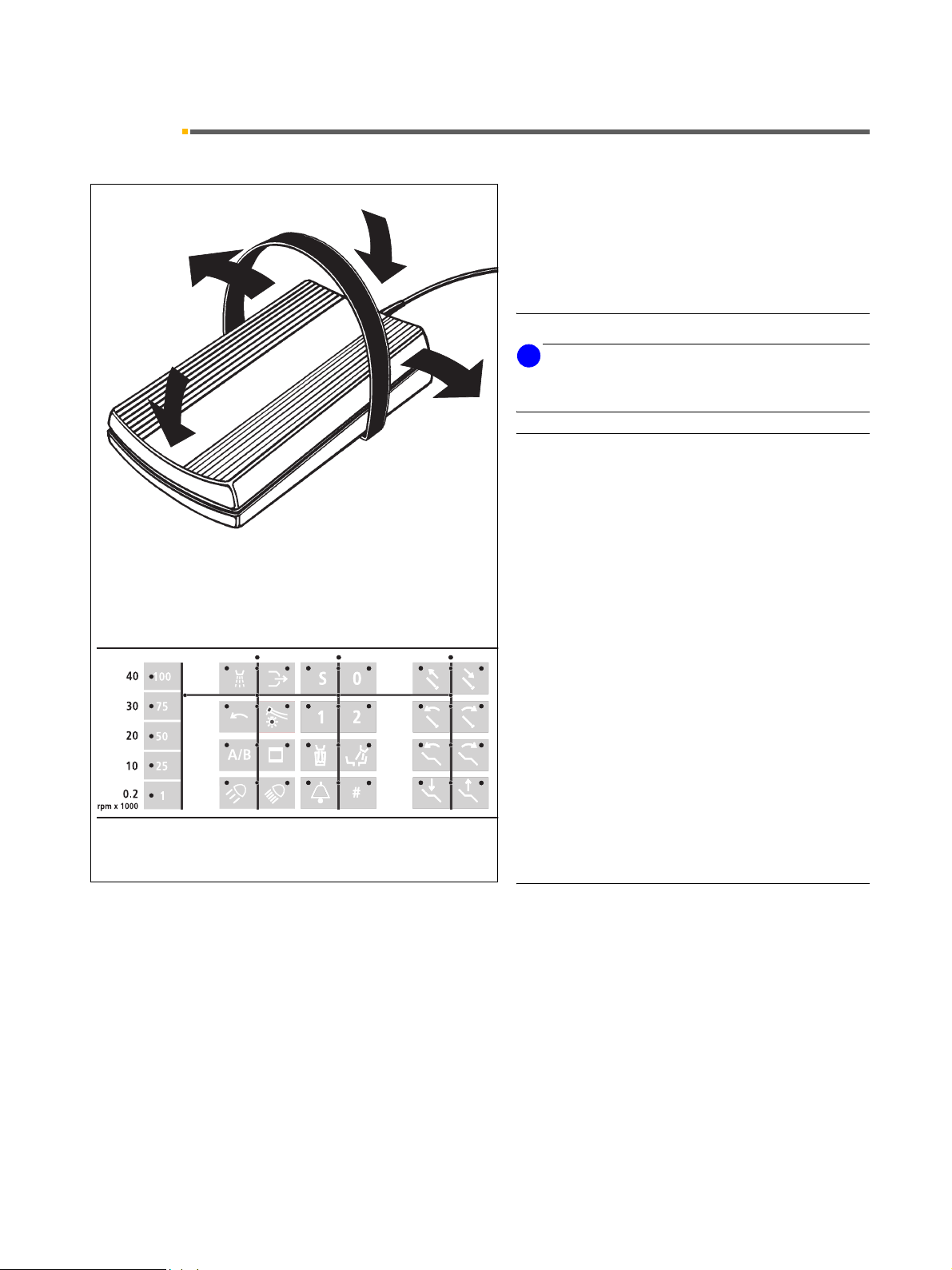
6.2 C foot switch
With this foot switch, all functions can be controlled
A*
C
using the entire pedal surface for hands-free working.
However, it is also possible to work manually by key
operation.
For cursor navigation, place your foot fully on the pedal
surface.
Functions (factory settings)
i
NOTICE
The foot switch functions A and B can be reversed by the
service engineer upon request.
B*
D
With cursor control enabled (Mode dialog 11.8)
Actuate foot switch in direction A – cursor upwards.
Actuate foot switch in direction B – cursor downwards.
Swing foot switch to the left C – cursor to the left.
Swing foot switch to the right D – cursor to the right.
Cursor navigation along the marked path and release of
the corresponding key function.
Instrument start
The cursor must be between the spray and the chip
blower key.
With instrument removed, actuate the foot switch in
direction A.
Moving the dentist element
If the cursor is between the headrest
in/out keys:
The dentist element moves toward the operator as long
as the foot switch is actuated (or toward the foot end of
the patient if reversed; this can be set by the service
engineer).
59 57 928 D 3370
D 3370.201.01.15.02
With cursor control disabled (Mode dialog
11.8)
Actuate foot switch in direction A:
With instrument removed – Activation of the instrument.
With instruments in place – The dentist element moves
toward the operator as long as the foot switch is actuated
(or toward the foot end of the patient if reversed; this can
be set by the service engineer).
Actuate foot switch in direction B:
With instrument removed – No function
23
6 Foot switch Sirona Dental Systems GmbH
6.2 C foot switch Operating Instructions C2
With instruments in place – The dentist element moves
away from the operator as long as the foot switch is actuated (or toward the operator if reversed; this can be set
by the service engineer).
Swing foot switch to the left C:
With instrument removed – Spray ON/OFF for burr
instruments or SIVISION function.
With instruments in place – SIVISION function.
Swing foot switch to the right D:
With instrument removed – Chip blower ON for burr
instruments or SIVISION function.
With instruments in place – SIVISION function.
Automatic cursor control with C foot switch
+
0.2
rpm x 1000
2.
3.
40
100
30
75
20
50
10
25
1
A/B
4.
SS1100
22
1.
A yellow diode on the dentist element indicates the position of the cursor. The cursor path is marked by lines.
1. After the unit is switched on or after entry/exit position 0 has been reached, the cursor is between the
move headrest out / in keys in the right key block. To
simplify hands-free headrest positioning, the cursor
jumps back between the move headrest out / in keys
if the instruments are removed only for wipe disinfection or for changing straight/contra-angle handpieces, but are not activated.
2. After the dentist element is moved using the foot
switch pedal, the cursor jumps between chair program keys 1 and 2.
3. On instrument removal or on activation of any instrument, the cursor jumps to a position between the
Spray and Chip blower keys in the first instrument
block.
If the cursor is in the quick setting key column at the
very left, it also jumps to a position between the
spray and chip blower keys in the instrument block
when the foot switch is swung to the right (D).
4. After the instrument is deposited, the cursor jumps
back to its position between chair program keys S
and 0.
24 D 3370.201.01.15.02
59 57 928 D 3370
Sirona Dental Systems GmbH 7 Program selection
Operating Instructions C2
+
7.1 Safety
7 Program selection
7.1 Safety
CAUTION
The patient’s arms and legs must be resting on the chair
upholstery during the program run!
CAUTION
Make sure that no obstacles (e.g. window wings, drawers, devices, …) extend into the movement range.
Safety stop
A
BACKREST
10:04:27
A built-in safety circuit stops the chair movement in the
following situations:
• The foot support collides with an obstacle.
• The backrest collides with an obstacle.
•The motorized headrest collides with an obstacle
• The swiveling cuspidor is swiveled in during chair
movement.
At the same time, a double-beep warning signal is
issued.
The chair then automatically moves upwards a short distance until the path has been cleared (except for the
swiveling cuspidor)
With instruments in place, the last activated safety
switch is indicated in plain text on the display:
• TILTING PART for motorized headrest
• BACKREST
• FOOT SUPPORT
CUSPIDOR appears on the display after 10 seconds if
the automatic return movement of the cuspidor to its
position is obstructed.
59 57 928 D 3370
D 3370.201.01.15.02
25
7 Program selection Sirona Dental Systems GmbH
7.2 Program selection Operating Instructions C2
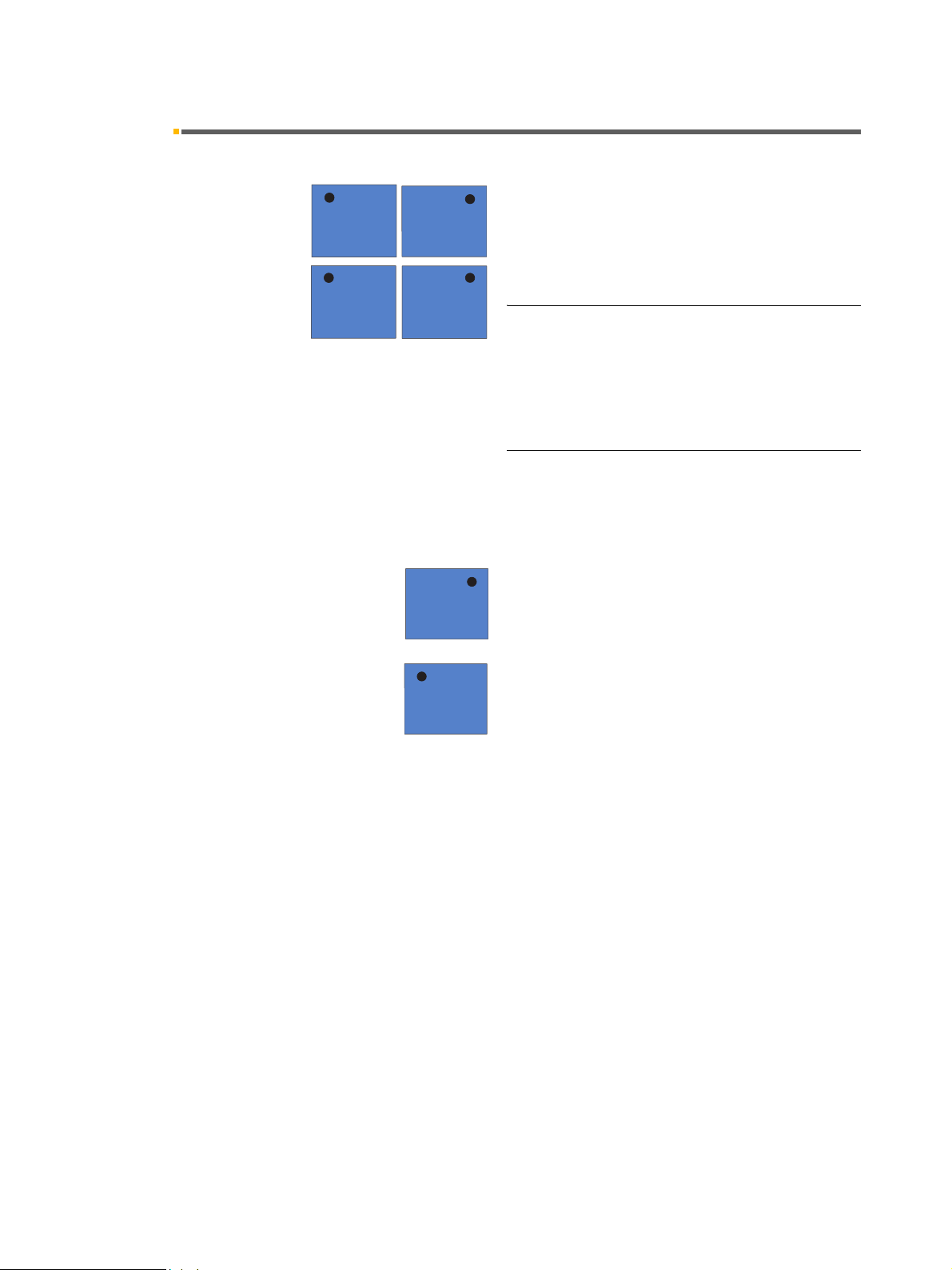
7.2 Program selection
Keys for selecting the programmed patient positions.
+
SS
11
00
22
00
SS
With swivelable cuspidor:
Before the chair moves into the selected program position, the swiveled in cuspidor moves back automatically
to its starting position.
Factory settings:
The operation light switches OFF automatically before
the chair moves into the entry/exit position 0 or into the
mouth rinsing position S.
The operation light switches ON automatically after the
chair has reached patient position 1 or 2.
Changing the factory settings:
When programming the patient positions you can preselect whether the operation light should switch OFF or ON
in the different chair programs 0, S, 1 or 2 (refer to page
29).
Program key 0
Intended for the entry/exit position.
Program key S with memory function.
In the S program it is possible to program the cuspidor
flushing and / or the tumbler filling function (see Mode
dialog 10.8 and 10.9).
If this key is pressed a second time, the treatment center
returns to its previous position (memory function).
Example: You have programmed this key for the mouth
rinsing position. When you press
ment center moves into the programmed position.
Memory function: When you press this key again, the
treatment center returns to its previous position.
26 D 3370.201.01.15.02
this key then the treat-
59 57 928 D 3370
Sirona Dental Systems GmbH 7 Program selection
Operating Instructions C2
+
7.3 MOVEMENT STOP!
7.3 MOVEMENT STOP!
Movement of the chair into a programmed position
can be stopped as follows:
• By pressing one of the chair-related keys located on the dentist and assistant elements.
• By actuating the 4-way foot control.
• By actuating the 4-way switch on a motor-adjustable headrest in any direction.
All movements of the treatment center are stopped
immediately.
At the same time, a double-beep warning signal is
issued.
Please note that pressing the program key of the
program which is just running once again does NOT
cause the movement to stop!
59 57 928 D 3370
D 3370.201.01.15.02
27
8 Patient positions Sirona Dental Systems GmbH
8.1 Headrest adjustable by motor drive Operating Instructions C2
8 Patient positions
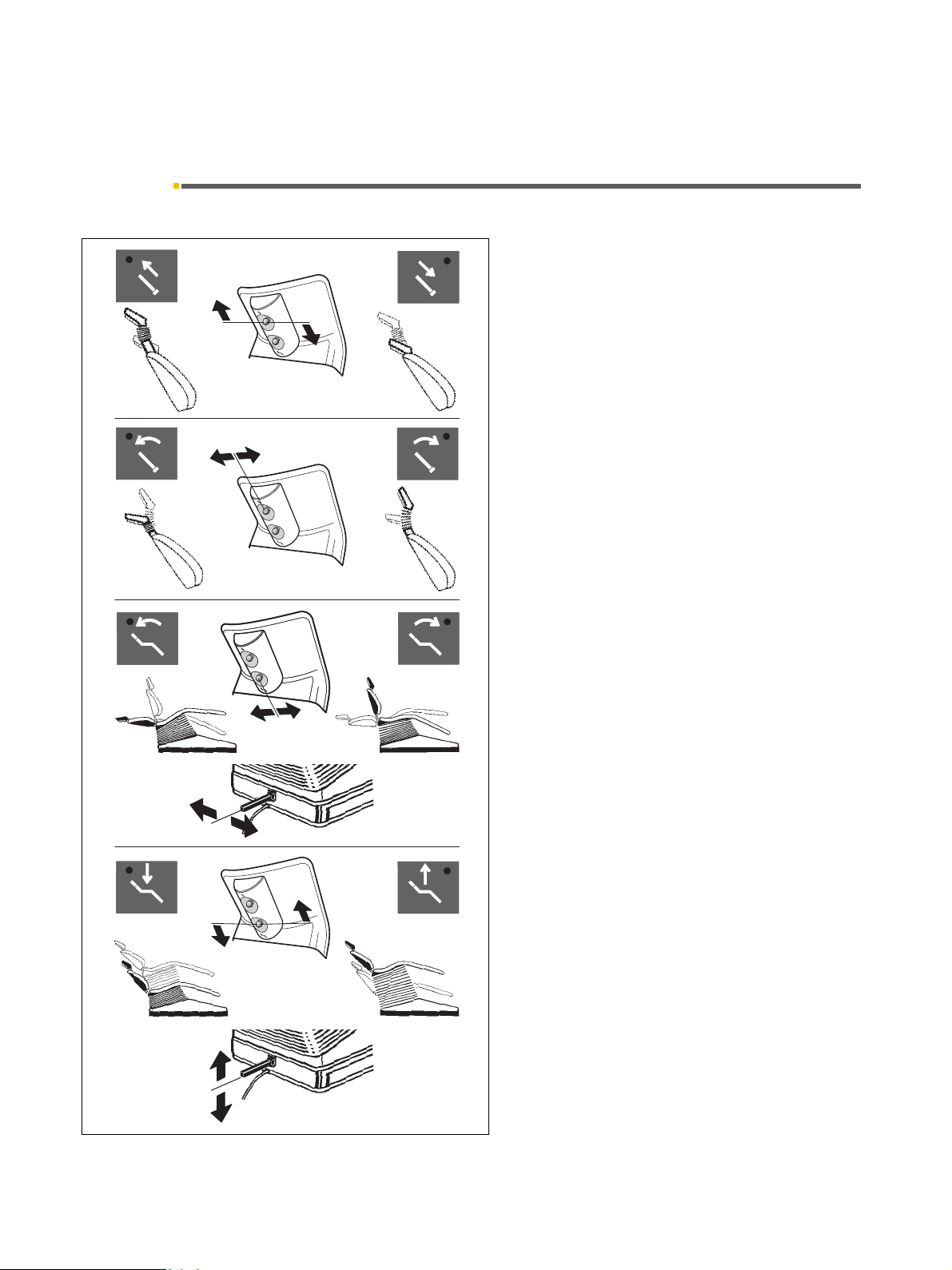
8.1 Headrest adjustable by motor drive
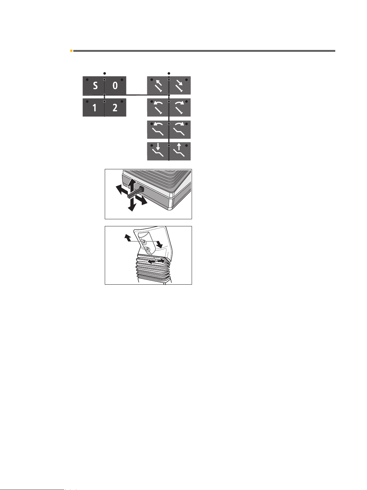
The keys located on the right key block of the dentist element control panel can be used to trigger the different
chair movements manually.
Move headrest out/in
The headrest can also be moved out or in with the two
upper keys in the right block on the assistant element
control panel and on the upper 4-way switch (up/down)
on the headrest.
Headrest tilt
The headrest can also be tilted to the back or front with
the upper 4-way switch on the headrest (left/right).
+
Headrest functions are also possible with the cuspidor
swung in.
Backrest tilt
The backrest can also be tilted with the 4-way foot control on the chair base
switch on the headrest.
Lever to the left:
Backrest tilts backwards.
Lever to the right:
Backrest tilts forward.
Height adjustment
The height can also be adjusted with the 4-way foot control on the chair base as well as with the lower 4-way
switch on the headrest.
Lever up:
The chair moves up.
Lever down:
The chair moves down.
*
as well as with the lower 4-way
Before backrest tilting or up/down movements are
started, the swiveled-in cuspidor automatically returns to
its starting position.
59 57 928 D 3370
28 D 3370.201.01.15.02
Sirona Dental Systems GmbH 8 Patient positions
Operating Instructions C2
+
8.2 Programming Patient Positions
8.2 Programming Patient Positions
Chair and dentist element
SS
11
00
22
The four factory-set programs can be changed individually by users A and B (observe the display) .
•Programs 1 and 2
• Entry/exit program 0
• Mouth rinsing program S
1. Move the chair into the desired
pressing the different setting keys (see page 28).
2. To have the SIROLUX FANTASTIC operation light
switch on or remain off when the chair reaches the
programmed treatment position, you must switch the
lamp ON or OFF now. This setting is then also programmed.
3. Now move the dentist element to the desired treatment position by hand.
CAUTION
In order to avoid damage to the dentist and assistant elements and to the chair upholstery, make sure that these
elements do not protrude into the movement range of the
chair.
treatment position by
4. To save the program settings, press the desired program key approx. 3 seconds until an acoustic signal
sounds and the LED of the corresponding key lights
up.
Programming is completed now.
i
NOTICE
Programming is not possible by activating the program
keys with the foot switch (cursor control). Thus programming errors are avoided.
59 57 928 D 3370
D 3370.201.01.15.02
29
8 Patient positions Sirona Dental Systems GmbH
A
8.3 MultiMotion headrest Operating Instructions C2
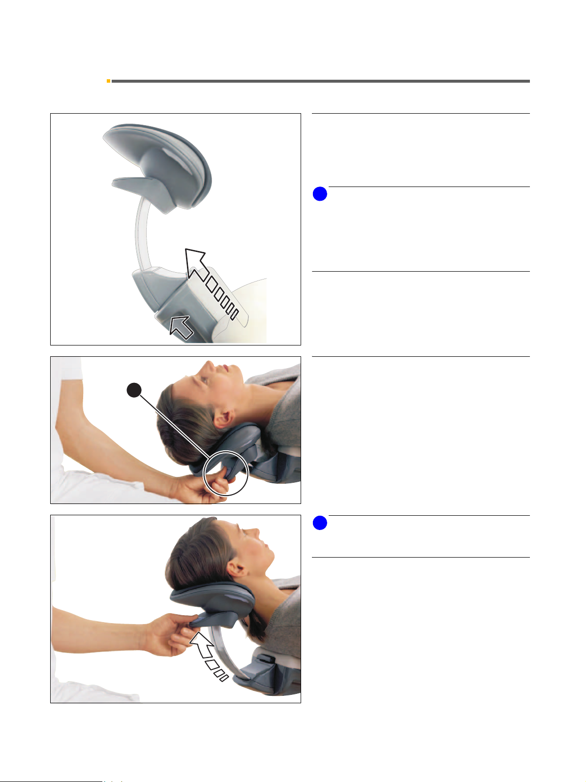
8.3 MultiMotion headrest
Adjustment to patient's height
The headrest can be adjusted to the patient's height by
pulling out or pushing in the headrest extension. This
adjustment is usually required at the beginning of treatment!
i
NOTICE
Before positioning the patient on the headrest, make
sure that the head support has been optimally adjusted
to the patient's height. This simplifies all subsequent
work with the MultiMotion considerably, since readjustment to the patient's height can thus be omitted when
changing over from mandibular to maxillary treatment.
The MultiMotion enables you to adjust the patient's head
in a way that optimally supports viewing of areas of the
mouth which are difficult to access.
+
Adjustment of hyperextension
Mandibular position
The mandibular position can be set by pulling the operating handle (A). The anatomical movement of the
arched extension keeps the patient's head in the support.
Pull the headrest out of the guide by pulling
handle A.
i
NOTICE
You can reduce the adjustment noise by pressing
release A.
30 D 3370.201.01.15.02
59 57 928 D 3370
Loading...