


Type 38-3AH3 38 kV vacuum circuit breaker instruction manual
Installation operation maintenance E50001-F710-A238-V1-4A00
Answers for energy.

Hazardous voltages and high speed moving parts.
Will cause death, serious injury or property damage.
Always de-energize and ground the equipment before maintenance. Read and understand this instruction manual before using equipment. Maintenance should be performed only by qualified personnel. The use of unauthorized parts in the repair of the equipment or tampering by unqualified personnel will result in dangerous conditions which will cause death, severe injury or equipment damage. Follow all safety instructions contained herein.
Important
The information contained herein is general in nature and not intended for specific application purposes. It does not relieve the user of responsibility to use sound practices in application, installation, operation and maintenance of the equipment purchased. Siemens reserves the right to make changes in the specifications shown herein or to make improvements at any time without notice or obligations. Should a conflict arise between the general information contained in this publication and the contents of drawings or supplementary material or both, the latter shall take precedence.
Qualified person
For the purpose of this instruction manual a qualified person is one who is familiar with the installation, construction or operation of the equipment and the hazards involved. In addition, this person has the following qualifications:
Is trained and authorized to de-energize, clear, ground and tag circuits and equipment in accordance with established safety procedures.
Is trained in the proper care and use of protective equipment, such as: rubber gloves, hard hat, safety glasses or face shields, flash clothing, etc., in accordance with established safety practices.
Is trained in rendering first aid.
Further, a qualified person shall also be familiar with the proper use of special precautionary techniques, personal protective equipment, insulating and shielding materials and insulated tools and test equipment. Such persons are permitted to work within limited approach of exposed live parts operating at 50 volts or more, and shall, at a minimum, be additionally trained in all of the following:
The skills and techniques necessary to distinguish exposed energized parts from other parts of electric equipment.
The skills and techniques necessary to determine the nominal voltage of exposed live parts.
The approach distances specified in NFPA 70E and the corresponding voltages to which the qualified person will be exposed.
The decision-making process necessary to determine the degree and extent of the hazard and the personal protective equipment and job planning necessary to perform the task safely.
2

Table of contents
Introduction |
4 |
- 5 |
Receiving, handling and storage |
6 |
- 8 |
Installation checks and functional tests |
9 |
- 13 |
Vacuum interrupter/operator |
14 - 39 |
|
Maintenance |
40 - 52 |
|
Overhaul |
53 - 58 |
|
Maintenance and troubleshooting |
59 - 61 |
|
Appendix |
62 - 67 |
|
Note:
These instructions do not purport to cover all details or variations in equipment, nor to provide for every possible contingency to be met in connection with installation, operation or maintenance. Should further information be desired or should particular problems arise that are not covered sufficiently for the purchaser’s purposes, the matter should be referred to the local sales office.
The contents of this instruction manual shall not become part of or modify any prior or existing agreement, commitment or relationship. The sales contract contains the entire obligation of Siemens Energy, Inc. The warranty contained in the contract between the parties is the sole warranty of Siemens Energy, Inc. Any statements contained herein do not create new warranties or modify the existing warranty.
3

Introduction
Hazardous voltage and high-speed moving parts.
Will cause death, serious injury and property damage.
Always de-energize and ground the equipment before maintenance. Maintenance should be performed only by qualified personnel. The use of unauthorized parts in the repair of the equipment or by tampering by unqualified personnel will result in dangerous conditions that will cause death, severe injury or equipment damage. Follow all safety instructions contained herein.
Introduction
The 38-3AH3 family of vacuum circuit breakers is designed to meet all applicable ANSI, NEMA and IEEE standards. Successful application and operation of this equipment depends as much upon proper installation and maintenance by the user as it does upon the proper design and fabrication by Siemens.
The purpose of this instruction manual is to assist the user in developing safe and efficient procedures for the installation, maintenance and use of the equipment.
Contact the nearest Siemens representative if any additional information is desired.
Signal words
The signal words "danger," "warning" and "caution" used in this instruction manual indicate the degree of hazard that may be encountered by the user. These words are defined as:
Danger - Indicates an imminently hazardous situation which, if not avoided, will result in death or serious injury.
Warning - Indicates a potentially hazardous situation which, if not avoided, could result in death or serious injury.
Caution - Indicates a potentially hazardous situation which, if not avoided, may result in minor or moderate injury.
Caution (without safety alert symbol) - Indicates a potentially hazardous situation which, if not avoided, may result in property damage.
Hazardous Procedures
In addition to other procedures described in this instruction manual as dangerous, user personnel must adhere to the following:
1.Always work only on a de-energized circuit breaker. The circuit breaker should be isolated, grounded and have all control power removed before performing any tests, maintenance or repair.
2.Always perform maintenance on the circuit breaker after the springcharged mechanisms are discharged (except for test of the charging mechanisms). Check to be certain that the indicator flags read OPEN and DISCHARGED.
3.Always let an interlock device or safety mechanism perform its function without forcing or defeating the device.
4
Introduction
Field service operation and warranty issues
Siemens can provide competent, well trained field service representatives to provide technical guidance and advisory assistance for the installation, overhaul, repair and maintenance of Siemens equipment, processes and systems. Contact regional service centers, sales offices or the factory for details, or telephone Siemens field service at
+1 (800) 347-6659 or +1 (919) 365-2200 outside the U.S.
For medium-voltage customer service issues, contact Siemens at
+1 (800) 347-6659 or +1 (919) 365-2200 outside the U.S.
5

Receiving, handling and storage
Heavy weight.
Improper lifting or hoisting can result in death, serious injury or property damage.
Obtain the services of a qualified rigger prior to hoisting the circuit breaker to assure adequate safety margins in the hoisting equipment and procedures to avoid damage.
Introduction
This portion of the instruction manual covers the receiving, handling and storage instructions for a type 38-3AH3 vacuum circuit breaker shipped separately from the switchgear. This section of the instruction manual is intended to help the user identify, inspect and protect the circuit breaker prior to its installation.
Receiving procedure
Make a physical inspection of the shipping container before removing or unpacking the circuit breaker.
Check for shipment damage or indications of rough handling by the carrier. Check each item against the manifest to identify any shortages.
Accessories such as the manual charging crank, the racking crank and the split plug jumper are shipped separately.
Shipping damage claims
Important: The manner in which visible shipping damage is identified by consignee prior to signing the delivery receipt can determine the outcome of any damage claim to be filed.
Notification to carrier within 15 days for concealed damage is essential if loss resulting from unsettled claims is to be eliminated or minimized.
1.When the shipment arrives, note whether the equipment is properly protected from the elements. Note the trailer number the equipment arrived on. Note also any blocking of equipment. During unloading, check the actual equipment delivered to verify it agrees with the delivery receipt.
2.Make immediate inspection for visible damage upon arrival and prior to disturbing or removing packaging or wrapping material. This should be done prior to unloading when possible. When total inspection cannot be made on vehicle prior to unloading, close inspection during unloading must be performed and visible damage noted on the delivery receipt. Take pictures if possible.
3.Any visible damage must be noted on the delivery receipt and acknowledged with the driver’s signature. The damage should be detailed as much as possible. It is essential that a notation "possible internal damage, subject to inspection" be included on the delivery receipt. If the driver will not sign the delivery receipt with the damage noted, the shipment should not be signed for by the consignee or their agent.
6

Receiving, handling and storage
4.Notify Siemens medium-voltage customer service immediately of any damage, at +1 (800) 347-6659 or +1 (919) 365-2200 outside the U.S.
5.Arrange for a carrier inspection of the damage immediately.
Important: Do not move the equipment from the place it was set when unloading. Also, do not remove or disturb packaging or wrapping material prior to carrier damage inspection. Equipment must be inspected by carrier prior to handling after receipt. This eliminates loss due to claims by carrier that the equipment was damaged or further damaged on site after unloading.
6.Be sure the equipment is properly protected from any further damage by covering it properly after unloading.
7.If practical, make further inspection for possible concealed damage while the carrier’s inspector is on site. If inspection for concealed damage is not practical at the time the carrier’s inspector is present, it must be done within 15 days of receipt of the equipment. If concealed damage is found, the carrier must again be notified and inspection made prior to taking any corrective action to repair. Also notify Siemens immediately at +1 (800) 3476659 or +1 (919) 365-2200 outside the U.S.
8.Obtain the original carrier inspection report and forward it with a copy of the noted delivery receipt to Siemens. Approval must be obtained by Siemens from the carrier before any repair work can be performed.
Before approval can be obtained, Siemens must have the documents referenced in the paragraph above. The carrier inspection report and/or driver’s signature on the delivery receipt does not constitute approval to repair.
Note: Any determination as to whether the equipment was properly loaded or properly prepared by shipper for over-the-road travel cannot be made at the destination. Shipments are not released from the factory without a clear bill of lading. Approved methods are employed for preparation, loading, blocking and tarping of the equipment before it leaves the Siemens factory. If the equipment is received in a damaged condition, this damage to the equipment has to have occurred while en route due to conditions beyond Siemens‘ control. If the procedure outlined above is not followed by the consignee, purchaser or their agent, Siemens cannot be held liable for repairs. Siemens will not be held liable for repairs in any case where repair work was performed prior to authorization from Siemens.
Handling procedure
1.Carefully remove the shipping carton from the circuit breaker. Keep the shipping pallet for later use if the circuit breaker is to be stored prior to its installation.
2.Inspect for concealed damage. Notification to carrier must take place within 15 days to assure prompt claim resolution.
3.Each circuit breaker should be lifted appropriately to avoid crushing the side panels of the circuit breaker, or damaging the primary disconnect assemblies.
Type 38-3AH3 vacuum circuit breakers weigh between 800 and 1,000 lbs (364-455 kg), plus an additional 125 pounds (57 kg) for the pallet and packaging.
4.The palleted circuit breaker can be moved using a properly rated fork-lift vehicle. The pallets are designed for movement by a standard fork-lift vehicle.
7
Receiving, handling and storage
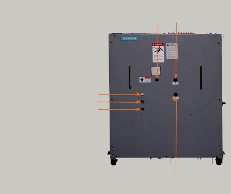
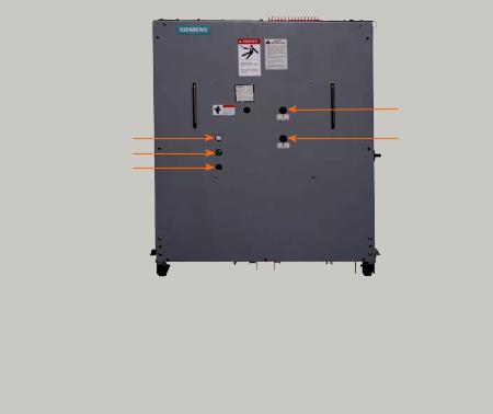
Manual spring-charging access port |
Manual close button |
CHARGED/DISCHARGED indicator
OPEN/CLOSED indicator
Operations counter
Manual open/trip button
Figure 1: Type 38-3AH3 vacuum circuit breaker front panel controls
Storage procedure
1.Whenever possible, install the circuit breaker in its assigned switchgear enclosure for storage. Follow instructions contained in the type GM38 38 kV metal-clad switchgear instruction manual, E50001-F710- A236-V1-4A00.
2.When the circuit breaker needs to be placed on its pallet for storage, be sure the unit is securely bolted to the pallet and covered with polyethylene film at least 10 mils thick.
Indoor storage
Whenever possible, store the circuit breaker indoors. The storage environment must be clean, dry and free of such items as construction dust, corrosive atmosphere, mechanical abuse and rapid temperature variations.
Outdoor storage
Outdoor storage is not recommended. When no other option is available, the circuit breaker must be completely covered and protected from rain, snow, dirt and all other contaminants.
Space heating
Space heating must be used for both indoor and outdoor storage to prevent condensation and corrosion. When the circuit breaker is stored outdoors, 250 watts per circuit breaker of space heating is recommended. If the circuit breaker is stored inside the switchgear enclosure, and the switchgear is equipped with space heaters, energize the space heaters.
8
Installation checks and functional tests
Hazardous voltage and high-speed moving parts.
Will cause death, serious injury and property damage.
Read instruction manuals, observe safety instructions and use qualified personnel.
Introduction
This section provides a description of the inspections, checks and tests to be performed on the circuit breaker prior to operation in the metal-clad switchgear.
Inspections, checks and tests without control power
Vacuum circuit breakers are normally shipped with their primary contacts OPEN and their springs DISCHARGED. However, it is critical to first verify the DISCHARGED condition of the spring-loaded mechanisms after de-energizing control power.
De-energizing control power in switchgear
When the circuit breaker is mounted in switchgear, open the control-power disconnect device in the metal-clad switchgear cubicle.
The control-power disconnect device is normally located on the secondary-device panel in the upper cell of the vertical section. The normal control-power disconnect device is a pullout-type fuse holder. Removal of the fuse holder deenergizes control power to the circuit breaker in the associated switchgear cell. In some switchgear assemblies, a moldedcase circuit breaker or knife switch is used in lieu of the pullout-type fuse holder. Opening this circuit breaker or switch accomplishes the same result: control power is disconnected.
Spring-discharge check (refer to Figure 1: Type 38-3AH3 vacuum circuit breaker front panel controls on page 8)
Perform the spring-discharge check before removing the circuit breaker from the pallet or removing it from the switchgear.
The spring-discharge check should be performed after de-energizing control power. This check assures both the tripping and closing springs are fully discharged.
Note: Do not perform the spring-discharge check if the circuit breaker is in the CONNECT position. Open the circuit breaker and rack to the DISCONNECT position, and then perform the springdischarge check.
1.Press red trip pushbutton.
2.Press black close pushbutton.
3.Press red trip pushbutton again.
4.Verify spring-condition indicator shows DISCHARGED.
5.Verify main contact status indicator shows OPEN.
9

Installation checks and functional tests
Heavy weight.
Can result in death, serious injury or property damage.
Observe all handling instructions in this instruction manual to prevent tipping or dropping of equipment.
Removal from cell in indoor switchgear if not on raised pad and Shelter-Clad outdoor switchgear
After performing the spring discharge check (with control power de-energized), remove the circuit breaker from its switchgear cubicle.
1.Insert the racking crank on the racking screw on the front of the circuit breaker cell, and push in (refer to "Racking crank engagement procedure" on page 11). This action operates the racking-interlock latch. Figure 2 shows circuit breaker racking.
2.Rotate the racking crank counterclockwise until the circuit breaker is in the DISCONNECT position, as indicated on the racking mechanism.
3.Move the circuit breaker release latch (on the floor of the cell near the right side of the circuit breaker) to the left and pull the circuit breaker out from the DISCONNECT position. The circuit breaker can now be removed from the cubicle.
4.The circuit breaker is now free to be rolled out onto the floor using the handles on the front. The wheels of the circuit breaker are at floor level (unless the switchgear is installed on a raised pad), and one person can normally handle the unit.
Removal from cell in outdoor non-walk- in enclosures or for indoor switchgear installed on a raised pad
Removal of the circuit breaker from a non- walk-in outdoor-switchgear assembly is similar to removal of a circuit breaker at floor level with several additional steps.
Figure 3 shows the two extension rails inserted into the fixed rails within the cell. The rails engage locking pins in the fixed rails to secure them in position. The procedure for removal of a circuit breaker not located at floor level is:
1.Close the circuit-breaker compartment door and secure all latches.
2.Insert the racking crank onto the racking screw on the front of the circuit-breaker cell, and push in (refer to "Racking crank engagement procedure" on page 11). This action operates the racking-interlock latch.
3.Rotate the racking crank counterclockwise until the circuit breaker is in the DISCONNECT position.
4.Open the circuit-breaker compartment door and insert the two extension rails into the fixed rails. Be sure the extension rails are properly secured in place.
10
Installation checks and functional tests
Heavy weight.
Can result in death, serious injury or property damage.
Do not transport a circuit breaker using a lift truck with the lift truck in the raised position.
Figure 2: Type 38-3AH3 vacuum circuit breaker racking
5.Move the circuit-breaker release latch (on the floor of the cell near the right side of the circuit breaker) to the left and pull the circuit breaker out from the DISCONNECT position. The circuit breaker can now be removed from the cubicle and rolled out onto the two extension rails.
6.Remove the circuit breaker from the two extension rails using the approved Siemens circuit-breaker lifting device or Siemens lifting sling and a suitable crane.
7.Lift the two extension rails and withdraw them from the switchgear.
8.Close the circuit-breaker compartment door and secure all latches.
Type 38-3AH3 vacuum circuit breakers weigh between 800 and 1,000 lbs (364455 kg) depending upon ratings. The circuit breaker can be moved using a properly rated crane and lift sling. A lift sling can be attached to the circuit breaker, and then used to hoist the circuit breaker vertically clear of the extension rails. When clear, remove the rails and lower the circuit breaker to the floor.
Racking crank engagement procedure
A crank for racking the circuit breaker is provided as a standard accessory. Racking a circuit breaker can be accomplished with the drawout-compartment-front door open or through a small opening (or window) in the front door, with the door closed. Racking a rollout-fuse truck is accomplished with the compartment-front door open.
The racking crank consists of an offset handle with a custom socket assembly welded to the end. The socket end of the crank is designed to engage the shoulder of the racking-mechanism shaft and remain engaged during racking with spring plungers. The plungers operate in a manner similar to the retainers of an ordinary mechanic’s socket wrench.
The portion of the racking-mechanism shaft visible is cylindrical, and the shoulder of the racking-mechanism shaft is hidden by a shroud until the engagement procedure starts. The square socket-end of the crank will only engage the shoulder of the shaft if it is aligned properly.
Figure 3: Use of extension rails for voltage transformer (VT) fuserollout truck or circuit breaker not at floor level (VT fuse-rollout truck in upper cell shown. Procedure for circuit breaker in lower cell but not at floor level is similar.)
11

Installation checks and functional tests
Figure 4: Manual charging of the closing springs
The suggested procedure to engage the racking mechanism is as follows:
1.The circuit breaker must be OPEN. (The racking shroud cannot be moved if the circuit breaker is CLOSED.)
2.Hold the socket-end of the crank in one hand and the crank handle in the other hand.
3.Place the socket over the end of the racking-mechanism shaft. Align the socket with the shoulder on the racking-mechanism shaft.
Note: If the socket is not aligned, the socket will not be able to engage the shoulder of the racking-mechanism shaft.
4.Once alignment is achieved, firmly push the crank and socket assembly toward the racking mechanism.
5.When properly engaged, the crank should remain connected to the racking mechanism. If the crank does not remain in position, adjust the spring plungers clockwise one-half turn. This will increase the contact pressure of the spring plunger.
6.To remove the crank, pull the assembly off of the racking-mechanism shaft.
Note: If the effort to rack the circuit breaker increases considerably during racking, or if turning of the racking crank requires excessive force, stop racking immediately. Do not try to force the racking crank to rotate, or parts of the circuit breaker or racking mechanism could be damaged. Determine the source of the problem and correct it before continuing with racking.
Physical inspections
1.Verify the rating of the circuit breaker is compatible with both the system and the switchgear.
2.Perform a visual-damage check. Clean the circuit breaker of all dust, dirt and foreign material.
Manual-spring charging check
1.Insert the manual-spring charging crank into the manual-charge handle socket as shown in Figure 4. Turn the crank clockwise (about 48 revolutions) until the spring condition indicator shows the closing spring is CHARGED.
2.Repeat the spring discharge check.
3.Verify the springs are DISCHARGED and the circuit-breaker primary contacts are OPEN by indicator positions.
As-found and vacuum-integrity check tests
Perform and record the results of both the as-found insulation test and the vacuumintegrity check (dielectric) test. Procedures for these tests are described in the Maintenance section of this instruction manual pages 40-52.
Automatic spring-charging check
Refer to the specific wiring information and rating label for your circuit breaker to determine the voltage required and where the control-voltage signal should be applied. Usually, spring-charging power is connected to secondary-disconnect fingers SD16 and SD15, closing control power to SD13 and SD15 and tripping power to SD1 and SD2.
When control power is connected to the type 38-3AH3 vacuum circuit breaker, the closing springs should automatically charge, if the racking crank is not engaged.
12
Installation checks and functional tests
Note: Secondary-disconnect terminals are numbered 1-16, from right to left.
The automatic spring-charging features of the circuit breaker must be checked. Control power is required for automatic spring-charging to take place.
1.Open control-power circuit by opening the control-power disconnect device.
2.Install the circuit-breaker end of the split-plug jumper (if furnished) to the circuit breaker as shown in Figure 5: Split-plug jumper connected to circuit breaker. The split-plug jumper is secured over the circuit-breaker secondary contacts with thumb screws.
3.Install the switchgear end of the splitplug jumper to the secondarydisconnect block inside the switchgear cubicle as shown in Figure 6: Split-plug jumper connected to switchgear. The jumper slides into place and interconnects all control power and signal leads (for example, electrical trip and close contacts) between the switchgear and the circuit breaker.
4.Energize (close) the control-power circuit disconnect.
5.Use the close and trip controls (refer to Figure 1: Type 38-3AH3 vacuum circuit breaker front panel controls on page 8) to first close and then open the circuit-breaker contacts. Verify the contact positions visually by observing the OPEN/CLOSED indicator on the circuit breaker.
6.De-energize control power by repeating Step 1. Disconnect the splitplug jumper from the switchgear before disconnecting the circuitbreaker end.
7.Perform the spring discharge check again. Verify the closing springs are DISCHARGED and the primary contacts of the type 38-3AH3 vacuum circuit breaker are OPEN.
Final mechanical inspections without control power
1.Make a final mechanical inspection of the circuit breaker. Verify the contacts are in the OPEN position, and the closing springs are DISCHARGED.
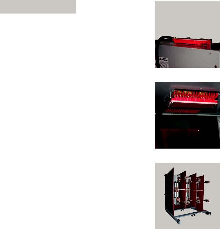
2.Check the upperand lower-primary studs and contact fingers shown in Figure 7: Circuit breaker primary disconnect. Verify mechanical condition of finger springs and the disconnect studs, check for loose hardware, damaged or missing primary-disconnect contact fingers and damaged disconnect studs.
3.Coat movable primary-contact fingers (refer to Figure 7: Circuit breaker primary disconnect) and the secondary-disconnect contacts (refer to Figure 23: Construction of secondary shunt release (shown charged) on page 30) with a light film of Siemens contact lubricant number 15-172-791-233.
4.The type 38-3AH3 vacuum circuit breaker is ready for installation into its assigned cubicle of the metal-clad switchgear. Refer to removal procedures and install the circuit breaker into the switchgear.
5.Refer to the switchgear instruction manual for functional tests of an installed circuit breaker.
Figure 5: Split-plug jumper connected to circuit breaker
Figure 6: Split-plug jumper connected to switchgear
Figure 7: Circuit breaker primary disconnects
13
Vacuum interrupter/ operator
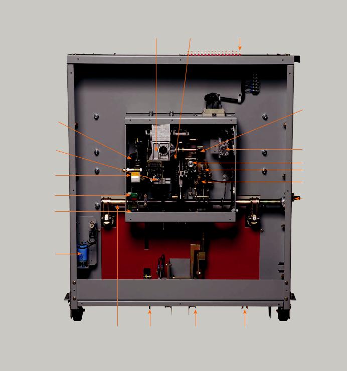
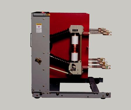
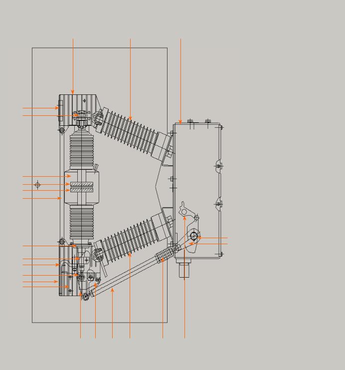
Figure 8: Front view of type 38-3AH3 vacuum circuit breaker with front panel removed
Gearbox |
Opening spring |
Secondary disconnect |
Closing spring
Spring-charging motor behind limit switches
CHARGED/
DISCHARGED indicator
OPEN/CLOSED indicator
Operations counter
Capacitor trip
(optional)
Push-to-close
Auxiliary switch
Close coil
Trip coil
Push-to-trip
Mechanismoperated cell (MOC) switch operator
Jack shaft |
Closed circuit- |
Trip-free interlock |
Ground disconnect |
|
breaker interlock |
|
|
14
Vacuum interrupter/ operator
Introduction
The type 38-3AH3 vacuum circuit breaker is of drawout construction designed for use in medium-voltage, metal-clad switchgear. The 38-3AH3 circuit breaker conforms to the requirements of ANSI and IEEE standards, including C37.20.2, C37.04, C37.06, C37.09 and C37.010.
A type 38-3AH3 vacuum circuit breaker consists of three vacuum interrupters, a stored-energy operating mechanism, necessary electrical controls and interlock devices, disconnect devices to connect the circuit breaker to both primary and control power and an operator housing. Insulating barriers are located along the outer sides and between phases as shown in
Figure 11: Type 38-3AH3 vacuum circuit breaker with inter-phase and outer-phase barriers installed on page 17.
This section describes the operation of each major sub-assembly as an aid in the operation, installation, maintenance and repair of the type 38-3AH3 vacuum circuit breaker.
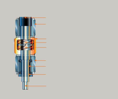
Vacuum interrupters
The operating principle of the vacuum interrupter is simple. Figure 9: Vacuum interrupter cutaway view is a cutaway view of a typical vacuum interrupter. The entire assembly is sealed after a vacuum is established. The vacuum-interrupter stationary contact is connected to the upper-disconnect stud of the circuit breaker. The vacuum-interrupter movable contact is connected to the lowerdisconnect stud and driving mechanism of the circuit breaker. The metal bellows provides a secure seal around the movable contact, preventing loss of vacuum while permitting vertical motion of the movable contact.
Fixed contact-current connection
Ceramic insulator
Arc shield
Fixed contact
Moving contact
Ceramic insulator
Metal bellows
Guide
Moving contact-current connection
Figure 9: Vacuum interrupter cutaway view
When the two contacts separate, an arc is initiated that continues conduction up to the following current zero. At current zero, the arc extinguishes and any conductive metal vapor that has been created by and supported by the arc condenses on the contacts and on the surrounding arc shield. Contact materials and configuration are optimized to achieve arc motion, resist welding and to minimize switching disturbances.
15
Vacuum interrupter/ operator
Figure 10: Upper and lower primary disconnects (outer-phase barrier removed)
Primary disconnects
Figure 10: Upper and lower primary disconnects (outer-phase barrier removed) is a side view of the circuit breaker with the outer-insulating phase barrier removed to show details of the primary disconnects. Each circuit breaker has three upperand three lower-primary disconnects. Upperprimary disconnects are connected to the stationary contacts of the vacuum interrupters, and the lower-primary disconnects are connected to the movable contacts. Each disconnect arm has a set of multiple spring-loaded fingers that mate with bus bars in the metal-clad switchgear. The number of fingers in the disconnect assembly varies with the continuous and/ or interrupting rating of the circuit breaker.
There are three insulating push rods. Each push rod connects the movable contact of one of the vacuum interrupters to the jack shaft driven by the closing and tripping mechanism. Flexible connectors provide secure electrical connections between the movable contacts of each vacuum interrupter and its bottom-primary disconnect.
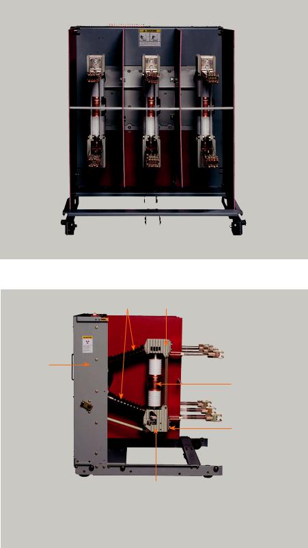
Phase barriers
Figure 11: Type 38-3AH3 vacuum circuit breaker with inter-phase and outer-phase barriers installed on page 17 is a rear view of a type 38-3AH3 vacuum circuit breaker that shows the outer- (phase-to-ground) and interphase-insulating barriers. These glass-polyester insulating barriers are attached to the circuit-breaker frame and provide suitable electrical insulation between the vacuum-interrupter primary circuits and the housing.
Stored-energy operating mechanism
The stored-energy operating mechanism of the type 38-3AH3 vacuum circuit breaker is an integrated arrangement of springs, solenoids and mechanical devices designed to provide a number of critical functions. The energy necessary to close and open (trip) the contacts of the vacuum interrupters is stored in powerful tripping and closing springs. The closing springs are normally charged automatically, but there are provisions for manual charging. The operating mechanism that controls charging, closing and tripping functions is fully trip-free. Trip-free requires that the tripping function prevail over the closing function as specified in ANSI/IEEE C37.04-1999, clause 6.9. The operation of the stored-energy mechanism will be discussed later in this section.
16
Vacuum interrupter/ operator
The vacuum circuit breaker consists of two sub-assemblies. The "interrupter/operator" module is a unitized assembly of the three vacuum interrupters, primary insulators and operating mechanism. The second module, the "vehicle", is the supporting drawout-structure module for the operating mechanism. The vehicle provides primary-stud extensions, closed circuit-breaker racking interlocks, closing spring discharge feature and other requirements needed to ensure safe and reliable use during racking and during operation. These two sub-assemblies will be separately described.
Interrupter/operator module
The interrupter/operator module consists of the three poles, each with its vacuum interrupter and primary insulators, mounted on the common motor or handcharged spring-stored energy-operating- mechanism housing. This module is shown in Figure 12: Interrupting/operating mechanism module (shown with outerphase barrier removed).
Construction
Refer to Figure 12: Interrupting/operating mechanism module (shown with outerphase barrier removed) on page 17, Figure 13: Operating mechanism controls and indicators on page 18, Figure 14: Type 383AH3 vacuum circuit breaker pole section on page 19 and Figure 15: Stored-energy operating mechanism on page 20.
Each of the circuit breaker poles is fixed to the rear of the operating-mechanism housing (60.0) by two cast-resin insulators (16.0).
The insulators also connect to the upper (20.0) and lower (40.0) pole-supports that in turn support the ends of the vacuum interrupter (30.0). Primary stud-extensions are attached directly to the upper polesupport (20.0) and lower terminal (29.0).
The energy-storing mechanism and all the control and actuating devices are installed in the mechanism housing (60.0).
The mechanism is of the spring storedenergy type and is mechanically and electrically trip-free.
Figure 11: Type 38-3AH3 vacuum circuit breaker with inter-phase and outer-phase barriers installed
16.020.0
60.0
30.0
29.0
|
|
40.0 |
|
16.0 |
- Insulator |
30.0 |
- Vacuum interrupter |
20.0 |
- Pole head |
40.0 |
- Pole bottom |
29.0 |
- Lower connection terminal |
60.0 |
- Operator housing |
Figure 12: Interrupter/operating mechanism module (shown with outer-phase barrier removed)
17
Vacuum interrupter/ operator
|
53.0 |
55.0 |
54.0 |
58.0 |
|
59.0 |
|
53.0 - Manual close button
54.0 - Manual open (trip) button
55.0 - CHARGED/DISCHARGED indicator
58.0 - OPEN/CLOSED indicator
59.0 - Operations counter
Figure 13: Operating mechanism controls and indicators
The OPEN/CLOSED indicator (58.0), CHARGED/DISCHARGED indicator (55.0) and the operations counter (59.0) are located on the front of the mechanism housing (60.0).
Circuit-breaker pole
Refer to Figure 14: Type 38-3AH3 vacuum circuit breaker pole section on page 19. The vacuum interrupter (30.0) is rigidly connected to the upper terminal and pole support (20.0) by its terminal bolt (31.2). The lower part of the vacuum interrupter is stabilized against lateral forces by a centering ring (28.1) on the pole-support (40.0). The external forces due to switching operations and the contact pressure are absorbed by the struts (28.0).
Current-path assembly
Refer to Figure 14: Type 38-3AH3 vacuum circuit breaker pole section on page 19. The current-path assembly consists of the upper terminal and pole support (20.0), the stationary contact (31.0) and the moving contact (36.0), that is connected with the lower terminal (29.0) by terminal clamp (29.2) and a flexible shunt (29.1).
Vacuum interrupter
Refer to Figure 9: Vacuum interrupter cutaway view on page 15. The movingcontact (36.0) motion is aligned and stabilized by guide bushing (35.0). The metal bellows (34.0) follows the travel of contact (36.0) and seals the vacuum interrupter against the surrounding atmosphere.
Switching operation
Refer to Figure 14: Type 38-3AH3 vacuum circuit breaker pole section on page 19. When a closing command is initiated, the closing spring, that was previously charged by hand or by the motor, actuates the moving contact (36.0) through jack shaft (63.0), lever (63.7), insulated coupler (48.0) and lever (48.6).
The motion of the insulated coupler is converted into the vertical movement of the moving contact.
The moving-contact motion is controlled by the guide link (48.9), that pivots on support (40.0) and the eye bolt (36.3).
During closing, the tripping spring and the contact-pressure springs (49.0) are charged and latched by the pawl (64.1). The closing spring is recharged immediately after closing.
In the CLOSED state, the necessary contact pressure is maintained by the contactpressure spring and the atmospheric pressure. The contact-pressure spring automatically compensates for contact erosion, which is very small.
18
Vacuum interrupter/ operator
Figure 14: Type 38-3AH3 vacuum circuit breaker pole section
20.0 |
16.0 |
60.0 |
27.0
31.2
30.0
31.0
36.0
28.0
28.1
29.2
29.1
36.3
29.0
40.0
16.0 - Insulator
20.0 - Pole head
27.0 - Upper-connection terminal
28.0- Strut
28.1- Centering ring
29.0- Lower-connection terminal
29.1- Flexible connector
29.2- Terminal clamp
30.0 - Vacuum interrupter
31.0 - Stationary contact
31.2 - Upper-terminal bolt
34.0 - Bellows (not shown)
35.0 - Guide bushing (not shown)
36.0 - Moving contact
36.3 - Eye bolt
40.0 - Pole bottom
48.0 - Insulating coupler
63.048.6 - Angled lever
63.748.9 - Guide link
49.0 - Contact-pressure spring
60.0 - Operator housing
63.0 - Jack shaft
63.7 - Lever
64.1- Pawl (not shown)
64.2- Pawl
48.6 |
48.9 |
48.0 |
16.0 |
49.0 |
64.2 |
19

Vacuum interrupter/ operator
Figure 15: Stored-energy operating mechanism
55.250.3 50.3.1 62.3 62.6 62.5 62.5.2
62.2 
50.2 
50.1 
55.1 
62.0 
50.4.1  55.0
55.0 
50.4 
58.0 
63.7 
59.0 
60.0 |
61.8 |
64.0 63.5 |
62.8 64.3 64.3.1 |
50.1- Manual-spring charging port
50.2- Charging-mechanism gear box
50.3- Charging flange
50.3.1 - Driver
50.4- Spring-charging motor (behind limit switches)
50.4.1 - Limit switches
53.0- Close button
53.1- Close coil
54.0- Open button
54.1- Trip coil
54.2- Undervoltage release (not shown)
55.0- Spring-charge indicator
55.1- Linkage
55.2- Control lever
58.0 - CLOSED/OPEN indicator
59.0 - Operation counter
60.0 - Operator housing
61.8- Shock absorber
62.0 - Closing spring
62.2- Crank
62.3- Cam disc
62.5- Lever
62.5.2 - Close-latch pawl
68.0
53.0
53.1
54.1
54.0
64.2
68.1
63.1
63.0
62.6- Driver lever
62.8 - Trip-free coupling rod
63.0- Jack shaft
63.1- Phase C lever
63.5 - Phase B lever
63.7 - Phase A lever
64.0 - Opening spring
64.2- Pawl
64.3- Lever
64.3.1 - Pawl roller
68.0- Auxiliary switch
68.1- Linkage
20
Vacuum interrupter/ operator
When a tripping command is given, the energy stored in the trippingand contactpressure springs is released by pawl (64.2). The opening sequence is similar to the closing sequence. The residual force of the tripping spring arrests the moving contact (36.0) in the OPEN (TRIPPED) position.
Operating mechanism
The operating mechanism is comprised of the mechanical and electrical components required to:
1.Charge the closing springs with sufficient potential energy to close the circuit breaker and to store opening energy in the trippingand contactpressure springs.
2.Means to initiate closing and tripping actions.
3.Means of transmitting force and motion to each of three poles.
4.Operate all of these functions automatically through electricalcharging motor, cutout switches, antipump relay, release (close and trip) solenoids and auxiliary switches.
5.Provide indication of the circuit breaker status (OPEN/CLOSED), spring condition (CHARGED/DISCHARGED) and number of operations.
Construction
The essential parts of the operating mechanism are shown in Figure 15: Stored-energy operating mechanism on page 20. The control and sequence of operation of the mechanism is described in the Operating mechanism section diagrams in Figure 17-21 on pages 24 through 28.
Indirect releases (tripping coils)
The shunt releases (54.1) convert the electrical-tripping pulse into mechanical energy to release the trip latch and open the circuit breaker.
The undervoltage release (optional) (54.2) may be electrically actuated by a make or a break contact.
If a make contact is used, the coil is shorted out, and a resistor must be used to limit the current. The undervoltage-release option mounts to the immediate right of the trip coil (54.1).
Motor-operating mechanism
The spring-charging motor (50.4) is bolted to the charging-mechanism (50.2) gear box installed in the mechanism housing. Neither the gear-box mechanism nor the motor require any normal maintenance.
Auxiliary switch
The auxiliary switch (68.0) is actuated by the jack shaft (63.0) and link (68.1).
Mode of operation
The operating mechanism is of the storedenergy trip-free type. In other words, the charging of the closing spring is not automatically followed by the contacts changing position, and the tripping function prevails over the closing function in accordance with ANSI/IEEE C37.041999, clause 6.9.
When the stored-energy mechanism has been charged, the circuit breaker can be closed manually or electrically at any desired time. The mechanical energy for carrying out an "open-close-open" sequence for auto-reclosing duty is stored in the closing and tripping springs.
Charging
The details of the closing-spring charging mechanism are shown in Figure 15: Stored-energy operating mechanism on page 20. The charging shaft is supported in the charging mechanism (50.2), but is not coupled mechanically with the charging mechanism.
Fitted to it are the crank (62.2) at one end, and the cam (62.3), together with lever (62.5) at the other.
When the charging mechanism is actuated by hand with a hand crank or by a motor (50.4), the flange (50.3) turns until the driver (50.3.1) locates in the cutaway part of the cam disc (62.3), thus causing the charging shaft to follow. The crank (62.2) charges the closing spring (62.0).
21
 Loading...