


 Loading...
MICROMASTER 420
Parameter List |
Issue04/02 |
User Documentation 6SE6400-5BA00-0BP0
Getting Started Guide
Is for quick commissioning with SDP and BOP.
Operating Instructions
Gives information about features of the MICROMASTER420, Installation, Commissioning, Control modes, System Parameter structure, Troubleshooting, Specifications and available options of the MICROMASTER420.
Parameter List
The Parameterlist containes the description of all Parameters structured in functional order and a detailed description. The Parameter list also includes a series of function plans.
Catalogues
In the catalogue you will find all needs to select a certain inverter, as well as filters chokes, operator panels or communications options.
MICROMASTER 420
Parameter List
User Documentation
Parameter List |
1 |
|
|
Function Diagrams |
2 |
|
|
Alarms and |
3 |
Warnings |
|
Valid for |
Issue 04/02 |
Converter Type |
Software Version |
MICROMASTER 420 |
V1.0 |
Issue 04/02

MM420 Parameter List |
04/02 |
Warning
!Please refer to all Definitiones and Warnings contained in the Operating Instructions. You will find the Operating Instructions on the Docu CD delivered with your inverter. If the CD is lost, it can be ordered via your local Siemens department under the Order No. 6SE6400-5AB00-1AP0.
Further information can be obtained from Internet website: http://www.siemens.de/micromaster
Approved Siemens Quality for Software and Training is to DIN ISO 9001, Reg. No. 2160-01
The reproduction, transmission or use of this document, or its contents is not permitted unless authorized in writing. Offenders will be liable for damages. All rights including rights created by patent grant or registration of a utility model or design are reserved.
© Siemens AG 2001. All Rights Reserved.
MICROMASTER® is a registered trademark of Siemens
Other functions not described in this document may be available. However, this fact shall not constitute an obligation to supply such functions with a new control, or when servicing.
We have checked that the contents of this document correspond to the hardware and software described. There may be discrepancies nevertheless, and no guarantee can be given that they are completely identical. The information contained in this document is reviewed regularly and any necessary changes will be included in the next edition. We welcome suggestions for improvement.
Siemens handbooks are printed on chlorine-free paper that has been produced from managed sustainable forests. No solvents have been used in the printing or binding process.
Document subject to change without prior notice.
Order number: 6SE6400-5BA00-0BP0 |
Siemens-Aktiengesellschaft. |
Printed in the Federal of Germany |
|
4 |
MICROMASTER 420 Parameter List |
6SE6400-5BA00-0BP0 |
04/02 |
1 Parameters |
Parameters MICROMASTER 420
This Parameter List must only be used together with the Operating Instructions or the Reference Manual of the MICROMASTER 420. Please pay special attention to the Warnings, Cautions, Notices and Notes contained in these manuals.
Table of Contents |
|
|
1 |
Parameters..................................................................................................................... |
7 |
1.1 |
Introduction to MICROMASTER 420 System Parameters ............................................ |
7 |
1.2 |
Quick commissioning (P0010=1) ................................................................................... |
9 |
1.3 |
Parameter Description.................................................................................................. |
11 |
2 |
Function Diagrams ..................................................................................................... |
111 |
3 |
Faults and Alarms...................................................................................................... |
135 |
3.1 |
MICROMASTER 420 fault messages........................................................................ |
135 |
3.2 |
MICROMASTER 420 alarm messages...................................................................... |
137 |
MICROMASTER 420 |
Parameter List |
6SE6400-5BA00-0BP0 |
5 |
04/02 |
1 Parameters |
1Parameters
1.1Introduction to MICROMASTER 420 System Parameters
The layout of the parameter description is as follows.
1 Par number |
2 Parameter name |
|
|
9 Min: |
12 Level: |
[index] |
3 CStat: |
5 Datatype |
7 Unit: |
10 Def: |
2 |
|
4 P-Group: |
6 active: |
8 Quick Comm: |
11 Max: |
|
|
13 |
Description: |
|
|
|
|
|
|
|
|
|
1.Parameter number
Indicates the relevant parameter number. The numbers used are 4-digit numbers in the range 0000 to 9999. Numbers prefixed with an “r” indicate that the parameter is a “read-only” parameter, which displays a particular value but cannot be changed directly by specifying a different value via this parameter number (in such cases, dashes “-“ are entered at the points “Unit”, “Min”, “Def” and “Max” in the header of the parameter description.
All other parameters are prefixed with a “P”. The values of these parameters can be changed directly in the range indicated by the “Min” and “Max” settings in the header.
[index] indicates that the parameter is an indexed parameter and specifies the number of indices available.
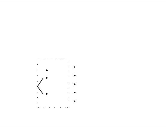
2.Parameter name
Indicates the name of the relevant parameter. Certain parameter names include
the following abbreviated prefixes: BI, BO, CI, and CO followed by a colon. These abbreviations have the following meanings:
BI |
= |
|
Binector input, i.e. parameter selects the source of a |
P9999.C |
(0) |
binary signal |
|
BO = CI =
CO =
r9999
P9999.D
(999:9)
r9999 [99]
Binector output, i.e. parameter connects as a binary signal
Connector input, i.e. parameter selects the source of an analog signal
Connector output, i.e. parameter connects as an analog signal
CO/BO = r9999 |
Connector/Binector output, i.e. parameter connects as an |
r9999 |
analog signal and/or as a binary signal |
To make use of BiCo you will need access to the full parameter list. At this level many new parameter settings are possible, including BiCo functionality. BiCo functionality is a different, more flexible way of setting and combining input and output functions. It can be used in most cases in conjunction with the simple, level 2 settings.
The BiCo system allows complex functions to be programmed. Boolean and mathematical relationships can be set up between inputs (digital, analog, serial etc.) and outputs (inverter current, frequency, analog output, relays, etc.).
3. CStat
Commissioning status of the parameter. Three states are possible:
Commissioning |
C |
Run |
U |
Ready to Run |
T |
This indicates when the parameter can be changed. One, two or all three states may be specified. If all three states are specified, this means that it is possible to change this parameter setting in all three inverter states
MICROMASTER 420 |
Parameter List |
6SE6400-5BA00-0BP0 |
7 |

MM420 Parameter List |
04/02 |
4.P-Group
Indicates the functional group of the particular.
Note
Parameter P0004 (parameter filter) acts as a filter and focuses access to parameters according to the functional group selected.
5.Datatype
The data types available are shown in the table below.
Notation |
Meaning |
U16 |
16-bit unsigned |
|
|
U32 |
32-bit unsigned |
|
|
I16 |
16-bit integer |
I32 |
32-bit integer |
|
|
Float |
Floating point |
6.Active
Indicates whether
♦ |
Immediately |
changes to the parameter values take effective immediately |
|
|
after they have been entered, or |
♦ |
Confirm |
the “P” button on the operator panel (BOP or AOP) must be |
|
|
pressed before the changes take effect. |
7.Unit
Indicates the unit of measure applicable to the parameter values
8.QuickComm
Indicates whether or not (Yes or No) a parameter can only be changed during quick commissioning, i.e. when P0010 (parameter groups for commissioning) is set to 1 (quick commissioning).
9.Min
Indicates the minimum value to which the parameter can be set.
10.Def
Indicates the default value, i.e. the value which applies if the user does not specify a particular value for the parameter.
11.Max
Indicates the maximum value to which the parameter can be set.
12.Level
Indicates the level of user access. There are four access levels: Standard, Extended, Expert and Service. The number of parameters that appear in each functional group depends on the access level set in P0003 (user access level).
13.Description
The parameter description consists of the sections and contents listed below. Some of these sections and contents are optional and will be omitted on a case- to-case basis if not applicable.
Description: Brief explanation of the parameter function.
Diagram: Where applicable, diagram to illustrate the effects of parameters on a characteristic curve, for example
Settings: List of applicable settings. These include
Possible settings, Most common settings, Index and Bitfields Example: Optional example of the effects of a particular parameter setting.
Dependency: Any conditions that must be satisfied in connection with this parameter. Also any particular effects, which this parameter has on other parameter(s) or which other parameters have on this one.
Warning / Caution / Notice / Note:
Important information which must be heeded to prevent personal injury or damage to equipment / specific information which should be heeded in order to avoid problems / information which may be helpful to the user
More details: Any sources of more detailed information concerning the particular parameter.
8 |
MICROMASTER 420 Parameter List |
6SE6400-5BA00-0BP0 |

04/02 |
1 Parameters |
1.2Quick commissioning (P0010=1)
The following parameters are necesarry for quick commissioning (P0010=1).
No |
Name |
Access level |
Cstat |
P0100 |
Europe / North America |
1 |
C |
P0300 |
Select motor type |
2 |
C |
P0304 |
Motor voltage rating |
1 |
C |
P0305 |
Motor current rating |
1 |
C |
P0307 |
Motor power rating |
1 |
C |
P0308 |
Motor cosPhi rating |
2 |
C |
P0309 |
Motor efficiency rating |
2 |
C |
P0310 |
Motor frequency rating |
1 |
C |
P0311 |
Motor speed rating |
1 |
C |
P0320 |
Motor magnetizing current |
3 |
CT |
P0335 |
Motor cooling |
2 |
CT |
P0640 |
Motor overload factor [%] |
2 |
CUT |
P0700 |
Selection of command source |
1 |
CT |
P1000 |
Selection of frequency setpoint |
1 |
CT |
P1080 |
Min. speed |
1 |
CUT |
P1082 |
Max. speed |
1 |
CT |
P1120 |
Ramp-up time |
1 |
CUT |
P1121 |
Ramp-down time |
1 |
CUT |
P1135 |
OFF3 ramp-down time |
2 |
CUT |
P1300 |
Control mode |
2 |
CT |
P1910 |
Select motor data identification |
2 |
CT |
P3900 |
End of quick commissioning |
1 |
C |
When P0010=1 is chosen, P0003 (user access level) can be used to select the parameters to be accessed. This parameter also allows selection of a user-defined parameter list for quick commissioning.
At the end of the quick commissioning sequence, set P3900 = 1 to carry out the necessary motor calculations and clear all other parameters (not included in P0010=1) to their default settings.
Note
This applies only in Quick Commissioning mode.
Reset to Factory default
To reset all parameters to the factory default settings; the following parameters should be set as follows:
Set P0010=30.
Set P0970=1.
Note
The reset process takes approximately 10 seconds to complete. Reset to Factory default
MICROMASTER 420 |
Parameter List |
6SE6400-5BA00-0BP0 |
9 |

MM420 Parameter List |
04/02 |
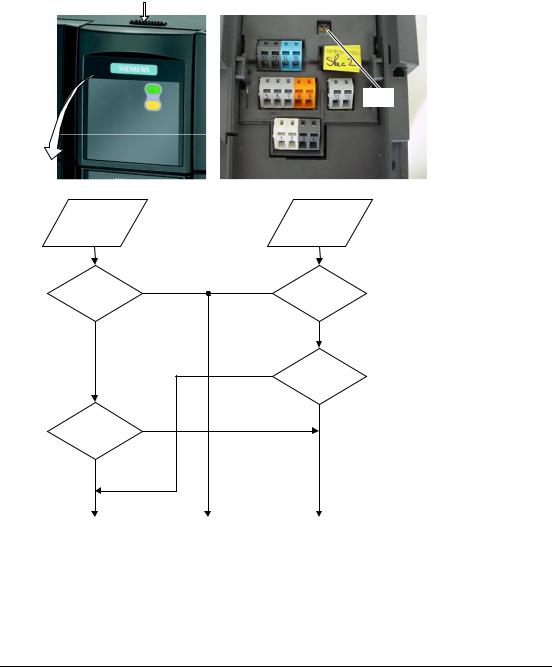
Seven-segment display
The seven-segment display is structured as follows:
Segment Bit 15 14 |
13 12 |
|
11 10 |
9 8 |
|
|
|||||||||||||||||||||||||||||||
|
|
|
|
|
|
|
|
|
|
|
|
|
|
|
|
|
|
|
|
|
|
|
|
|
|
|
|
|
|
|
|
|
|
|
|
|
|
|
|
|
|
|
|
|
|
|
|
|
|
|
|
|
|
|
|
|
|
|
|
|
|
|
|
|
|
|
|
|
|
|
|
|
|
|
|
|
|
|
|
|
|
|
|
|
|
|
|
|
|
|
|
|
|
|
|
|
|
|
|
|
|
|
|
|
|
|
|
|
|
|
|
|
|
|
|
|
|
|
|
|
|
|
|
|
|
|
|
|
|
|
|
|
|
|
|
|
|
|
|
|
|
|
|
|
|
|
|
|
|
|
|
|
|
|
|
|
|
|
|
|
|
|
|
|
|
|
|
|
|
|
|
|
|
|
|
|
|
|
|
|
|
|
|
|
|
|
|
|
|
|
|
|
|
|
|
|
|
|
|
|
|
|
|
|
|
|
|
|
|
|
|
|
|
|
|
|
|
|
|
|
|
|
|
|
|
|
|
|
|
|
|
|
|
|
|
|
|
|
|
|
|
|
|
|
|
|
|
|
|
|
|
|
|
|
|
|
|
|
|
|
|
|
|
|
|
|
|
|
|
|
|
|
|
|
|
|
|
|
|
|
|
|
|
|
|
|
|
|
|
|
|
|
|
|
|
|
|
|
|
|
|
|
|
Segment Bit 7 6 |
5 4 |
3 2 |
1 0 |
The significance of the relevant bits in the display is described in the status and control word parameters.
10 |
MICROMASTER 420 Parameter List |
6SE6400-5BA00-0BP0 |
04/02 |
1 Parameters |
1.3Parameter Description
Note:
Level 4 Parameters are not visible with BOP or AOP.
r0000 |
Drive display |
|
Min: |
- |
Level: |
|
Datatype: U16 |
Unit: - |
Def: |
- |
1 |
|
P-Group: ALWAYS |
|
Max: |
- |
|
|
|
|
Displays the user selected output as defined in P0005.
Note:
Pressing the "Fn" button for 2 seconds allows the user to view the values of DC link voltage, output frequency, output voltage, output current, and chosen r0000 setting (defined in P0005).
r0002 |
Drive state |
|
Min: |
- |
Level: |
|
Datatype: U16 |
Unit: - |
Def: |
- |
2 |
|
P-Group: COMMANDS |
|
Max: |
- |
|
|
|
|
Displays actual drive state.
Possible Settings:
0Commissioning mode (P0010 != 0)
1Drive ready
2Drive fault active
3Drive starting (DC-link precharging)
4Drive running
5 |
Stopping (ramping down) |
Dependency: |
|
State 3 visible only while precharging DC link, and when externally powered communications board is fitted.
P0003 |
User access level |
|
|
Min: |
0 |
Level: |
|
|
CStat: |
CUT |
Datatype: U16 |
Unit: - |
Def: |
1 |
1 |
|
P-Group: |
ALWAYS |
Active: first confirm |
QuickComm. No |
Max: |
4 |
|
|
|
||||||
Defines user access level to parameter sets. The default setting (standard) is sufficient for most simple applications.
Possible Settings:
0User defined parameter list - see P0013 for details on use
1Standard: Allows access into most frequently used parameters.
2Extended: Allows extended access e.g. to inverter I/O functions.
3Expert: For expert use only.
4Service: Only for use by authorized service personal - password protected.
P0004 |
Parameter filter |
|
|
Min: |
0 |
Level: |
|
|
CStat: |
CUT |
Datatype: U16 |
Unit: - |
Def: |
0 |
1 |
|
P-Group: |
ALWAYS |
Active: first confirm |
QuickComm. No |
Max: |
22 |
|
|
|
||||||
Filters available parameters according to functionality to enable a more focussed approach to commissioning.
Possible Settings:
0All parameters
2Inverter
3Motor
7Commands, binary I/O
8ADC and DAC
10 Setpoint channel / RFG
12Drive features
13Motor control
20Communication
21Alarms / warnings / monitoring
22Technology controller (e.g. PID)
Example:
P0004 = 22 specifies that only PID parameters will be visible.
Dependency:
Parameters marked "Quick Comm: Yes" in the parameter header can only be set when P0010 = 1 (Quick Commissioning).
MICROMASTER 420 |
Parameter List |
6SE6400-5BA00-0BP0 |
11 |

MM420 Parameter List |
|
|
|
|
04/02 |
||
|
|
|
|
|
|
|
|
P0005 |
Display selection |
|
|
Min: |
0 |
Level: |
|
|
CStat: |
CUT |
Datatype: U16 |
Unit: - |
Def: |
21 |
2 |
|
P-Group: |
FUNC |
Active: first confirm |
QuickComm. No |
Max: |
4000 |
|
Selects display for parameter r0000 (drive display).
Common Settings:
21 Actual frequency
25Output voltage
26DC link voltage
27Output current
Notice:
These settings refer to read only parameter numbers ("rxxxx").
Details:
|
See relevant "rxxxx" parameter descriptions. |
|
|
|
|
||
P0006 |
Display mode |
|
|
Min: |
0 |
Level: |
|
|
CStat: |
CUT |
Datatype: U16 |
Unit: - |
Def: |
2 |
3 |
|
P-Group: |
FUNC |
Active: first confirm |
QuickComm. No |
Max: |
4 |
|
Defines mode of display for r0000 (drive display).
Possible Settings:
0In Ready state alternate between setpoint and output frequency. In run display output frequency
1In Ready state display setpoint. In run display output frequency.
2In Ready state alternate between P0005 value and r0020 value. In run display P0005 value
3In Ready state alternate between r0002 value and r0020 value. In run display r0002 value
4In all states just display P0005
Note:
When inverter is not running, the display alternates between the values for "Not Running" and "Running". Per default, the setpoint and actual frequency values are displayed alternately.
P0007 |
Backlight delay time |
|
|
Min: |
0 |
Level: |
|
|
CStat: |
CUT |
Datatype: U16 |
Unit: - |
Def: |
0 |
3 |
|
P-Group: |
FUNC |
Active: first confirm |
QuickComm. No |
Max: |
2000 |
|
|
|
||||||
Defines time period after which the backlight display turns off if no operator keys have been pressed.
Value:
P0007 = 0:
Backlight always on (default state).
P0007 = 1 - 2000:
Number of seconds after which the backlight will turn off.
P0010 |
Commissioning parameter |
|
Min: |
0 |
Level: |
||
|
CStat: |
CT |
Datatype: U16 |
Unit: - |
Def: |
0 |
1 |
|
P-Group: |
ALWAYS |
Active: first confirm |
QuickComm. No |
Max: |
30 |
|
Filters parameters so that only those related to a particular functional group are selected.
Possible Settings:
0Ready
1Quick commissioning
2Inverter
29Download
30Factory setting
Dependency:
Reset to 0 for inverter to run.
P0003 (user access level) also determines access to parameters.
Note:
P0010 = 1
The inverter can be commissioned very quickly and easily by setting P0010 = 1. After that only the important parameters (e.g.: P0304, P0305, etc.) are visible. The value of these parameters must be entered one after the other. The end of quick commissioning and the start of internal calculation will be done by setting P3900 = 1 - 3. Afterward parameter P0010 will be reset to zero automatically.
P0010 = 2
For service purposes only.
P0010 = 29
To transfer a parameter file via PC tool (e.g.: DriveMonitor, STARTER) parameter P0010 will be set to 29 by the PC tool. When download has been finished PC tool resets parameter P0010 to zero.
P0010 = 30
|
When resetting the parameters of inverter P0010 must be set to 30. Resetting of the parameters will be |
|
started by setting parameter P0970 = 1. The inverter will automatically reset all its parameters to their |
|
default settings. This can prove beneficial if you experience problems during parameter setup and wish to |
|
start again. Duration of factory setting will take about 60 s. |
|
If P3900 is not 0 (0 is the default value), this parameter is automatically reset to 0. |
12 |
MICROMASTER 420 Parameter List |
6SE6400-5BA00-0BP0 |

04/02 |
|
|
|
|
|
1 Parameters |
|
|
|
|
|
|
|
||
P0011 |
Lock for user defined parameter |
|
Min: |
0 |
Level: |
||
|
CStat: |
CUT |
Datatype: U16 |
Unit: - |
Def: |
0 |
3 |
|
P-Group: |
FUNC |
Active: first confirm |
QuickComm. No |
Max: |
65535 |
|
Details: |
|
|
|
|
|
|
|
|
See parameter P0013 (user defined parameter) |
|
|
|
|
||
P0012 |
Key for user defined parameter |
|
Min: |
0 |
Level: |
||
|
CStat: |
CUT |
Datatype: U16 |
Unit: - |
Def: |
0 |
3 |
|
P-Group: |
FUNC |
Active: first confirm |
QuickComm. No |
Max: |
65535 |
|
Details: |
|
|
|
|
|
|
|
|
See parameter P0013 (user defined parameter). |
|
|
|
|
||
P0013[20] |
User defined parameter |
|
|
Min: |
0 |
Level: |
|
|
CStat: |
CUT |
Datatype: U16 |
Unit: - |
Def: |
0 |
3 |
|
|
||||||
|
P-Group: |
FUNC |
Active: first confirm |
QuickComm. No |
Max: |
65535 |
|
Defines a limited set of parameters to which the end user will have access.
Instructions for use:
Step 1: Set P0003 = 3 (expert user)
Step 2: Go to P0013 indices 0 to 16 (user list)
Step 3: Enter into P0013 index 0 to 16 the parameters required to be visible in the user-defined list. The following values are fixed and cannot be changed:
-P0013 index 19 = 12 (key for user defined parameter)
-P0013 index 18 = 10 (commissioning parameter filter)
-P0013 index 17 = 3 (user access level)
Step 4: Set P0003 = 0 to activate the user defined parameter.
Index:
P0013[0] : 1st user parameter P0013[1] : 2nd user parameter P0013[2] : 3rd user parameter P0013[3] : 4th user parameter P0013[4] : 5th user parameter P0013[5] : 6th user parameter P0013[6] : 7th user parameter P0013[7] : 8th user parameter P0013[8] : 9th user parameter P0013[9] : 10th user parameter P0013[10] : 11th user parameter P0013[11] : 12th user parameter P0013[12] : 13th user parameter P0013[13] : 14th user parameter P0013[14] : 15th user parameter P0013[15] : 16th user parameter P0013[16] : 17th user parameter P0013[17] : 18th user parameter P0013[18] : 19th user parameter P0013[19] : 20th user parameter
Dependency:
First, set P0011 ("lock") to a different value than P0012 ("key") to prevent changes to user-defined parameter. Then, set P0003 to 0 to activate the user-defined list.
When locked and the user-defined parameter is activated, the only way to exit the user-defined parameter (and view other parameters) is to set P0012 ("key") to the value in P0011 ("lock").
Note:
Alternatively, set P0010 = 30 (commissioning parameter filter = factory setting) and P0970 = 1 (factory reset) to perform a complete factory reset.
|
The default values of P0011 ("lock") and P0012 ("key") are the same. |
|
|
|
|
r0018 |
Firmware version |
|
Min: |
- |
Level: |
|
Datatype: Float |
Unit: - |
Def: |
- |
1 |
|
|
||||
|
P-Group: INVERTER |
|
Max: |
- |
|
Displays version number of installed firmware.
MICROMASTER 420 |
Parameter List |
6SE6400-5BA00-0BP0 |
13 |

MM420 Parameter List |
|
|
|
04/02 |
|||
|
|
|
|
|
|
|
|
r0019 |
|
CO/BO: BOP control word |
|
Min: |
- |
Level: |
|
|
|
|
Datatype: U16 |
Unit: - |
Def: |
- |
3 |
|
|
P-Group: |
COMMANDS |
|
Max: |
- |
|
|
|
Displays status of operator panel commands. |
|
|
|
|
|
|
|
The settings below are used as the "source" codes for keypad control when connecting to BICO input |
|||||
|
|
parameters. |
|
|
|
|
|
|
Bitfields: |
|
|
|
|
|
|
|
|
Bit00 |
ON/OFF1 |
0 |
NO |
|
|
|
|
|
|
1 |
YES |
|
|
|
|
Bit01 |
OFF2: Electrical stop |
0 |
YES |
|
|
|
|
|
|
1 |
NO |
|
|
|
|
Bit08 |
JOG right |
0 |
NO |
|
|
|
|
|
|
1 |
YES |
|
|
|
|
Bit11 |
Reverse (setpoint inversion) |
0 |
NO |
|
|
|
|
|
|
1 |
YES |
|
|
|
|
Bit13 |
Motor potentiometer MOP up |
0 |
NO |
|
|
|
|
|
|
1 |
YES |
|
|
|
|
Bit14 |
Motor potentiometer MOP down |
0 |
NO |
|
|
|
|
|
|
1 |
YES |
|
|
Note:
When BICO technology is used to allocate functions to panel buttons, this parameter displays the actual status of the relevant command.
The following functions can be "connected" to individual buttons: - ON/OFF1,
- OFF2,
- JOG,
- REVERSE,
- INCREASE,
- DECREASE
r0020 |
CO: Freq. setpoint before RFG |
|
Min: |
- |
Level: |
|
Datatype: Float |
Unit: Hz |
Def: |
- |
3 |
|
|
||||
|
P-Group: CONTROL |
|
Max: |
- |
|
|
Displays actual frequency setpoint (output from ramp function generator). |
|
|
|
|
r0021 |
CO: Act. frequency |
|
Min: |
- |
Level: |
|
Datatype: Float |
Unit: Hz |
Def: |
- |
2 |
|
P-Group: CONTROL |
|
Max: |
- |
|
|
Displays actual inverter output frequency (r0024) excluding slip compensation, resonance damping and |
||||
|
frequency limitation. |
|
|
|
|
r0022 |
Act. filtered rotor speed |
|
Min: |
- |
Level: |
|
Datatype: Float |
Unit: 1/min |
Def: |
- |
3 |
|
P-Group: CONTROL |
|
Max: |
- |
|
Displays calculated rotor speed based on inverter output frequency [Hz] x 120 / number of poles.
Note:
|
This calculation makes no allowance for load-dependent slip. |
|
|
|
|
r0024 |
CO: Act. output frequency |
|
Min: |
- |
Level: |
|
Datatype: Float |
Unit: Hz |
Def: |
- |
3 |
|
|
||||
|
P-Group: CONTROL |
|
Max: |
- |
|
|
Displays actual output frequency (slip compensation, resonance damping and frequency limitation are |
||||
|
included). |
|
|
|
|
r0025 |
CO: Act. output voltage |
|
Min: |
- |
Level: |
|
Datatype: Float |
Unit: V |
Def: |
- |
2 |
|
P-Group: CONTROL |
|
Max: |
- |
|
|
Displays [rms] voltage applied to motor. |
|
|
|
|
r0026 |
CO: Act. filtered DC-link volt. |
|
Min: |
- |
Level: |
|
Datatype: Float |
Unit: V |
Def: |
- |
2 |
|
P-Group: INVERTER |
|
Max: |
- |
|
|
Displays DC-link voltage. |
|
|
|
|
r0027 |
CO: Act. output current |
|
Min: |
- |
Level: |
|
Datatype: Float |
Unit: A |
Def: |
- |
2 |
|
P-Group: CONTROL |
|
Max: |
- |
|
Displays [rms] value of motor current [A].
14 |
MICROMASTER 420 Parameter List |
6SE6400-5BA00-0BP0 |

04/02 |
|
|
|
|
1 Parameters |
|
|
|
|
|
|
|
|
r0034 |
CO: Motor temperature (i2t) |
|
Min: |
- |
|
Level: |
|
Datatype: Float |
Unit: % |
Def: |
- |
|
2 |
|
P-Group: MOTOR |
|
Max: |
- |
|
|
Displays calculated motor temperature (I2t model) as [%] of the maximum permissible value.
Note:
A value of 100 % means that the motor has reached its maximum permissible operating temperature. In this case, the motor will attempt to reduce the motor loading as defined in P0610 (motor I2t temperature reaction).
r0036 |
CO:Inverter overload utilization |
|
Min: |
- |
Level: |
|
Datatype: Float |
Unit: % |
Def: |
- |
4 |
|
P-Group: INVERTER |
|
Max: |
- |
|
|
|
|
Displays inverter overload utilization calculated via I2t model.
The actual I2t value relative to the max. possible I2t value supplies utilization in [%].
If the nominal current of the inverter is not exceed, 0 % utilization will be displayed.
If the current exceeds the threshold for P0294 (inverter I2t overload warning), alarm A0504 (inverter overtemperature) is generated and the output current of the inverter reduced via P0290 (inverter overload reaction).
If 100 % utilization is exceeded, alarm F0005 (inverter I2T) is tripped.
r0037 |
CO: Inverter temperature [°C] |
|
Min: |
- |
Level: |
||
|
|
|
Datatype: Float |
Unit: °C |
Def: |
- |
3 |
|
P-Group: |
INVERTER |
|
|
Max: |
- |
|
|
Displays internal inverter heatsink temperature. |
|
|
|
|
||
r0039 |
CO: Energy consumpt. meter [kWh] |
|
Min: |
- |
Level: |
||
|
|
|
Datatype: Float |
Unit: kWh |
Def: |
- |
2 |
|
P-Group: |
INVERTER |
|
|
Max: |
- |
|
|
Displays electrical energy used by inverter since display was last reset (see P0040 - reset energy |
|
|||||
|
consumption meter). |
|
|
|
|
|
|
Dependency: |
|
|
|
|
|
|
|
|
Value is reset when |
|
|
|
|
|
|
|
P0040 = 1 reset energy consumption meter. |
|
|
|
|
||
P0040 |
Reset energy consumption meter |
|
Min: |
0 |
Level: |
||
|
CStat: |
CT |
Datatype: U16 |
Unit: - |
Def: |
0 |
2 |
|
P-Group: |
INVERTER |
Active: first confirm |
QuickComm. No |
Max: |
1 |
|
Resets value of parameter r0039 (energy consumption meter) to zero.
Possible Settings:
0No reset
1 |
Reset r0039 to 0 |
Dependency: |
|
No reset until "P" is pressed.
MICROMASTER 420 |
Parameter List |
6SE6400-5BA00-0BP0 |
15 |
MM420 Parameter List |
|
|
|
04/02 |
|||
|
|
|
|
|
|
|
|
r0052 |
|
CO/BO: Act. status word 1 |
|
Min: |
- |
Level: |
|
|
|
|
Datatype: U16 |
Unit: - |
Def: |
- |
2 |
|
|
P-Group: |
COMMANDS |
|
Max: |
- |
|
|
|
Displays first active status word of inverter (bit format) and can be used to diagnose inverter status. The |
|||||
|
|
display segments for the status word are shown in the "Introduction to MICROMASTER System |
|
||||
|
|
Parameters". |
|
|
|
|
|
|
Bitfields: |
|
|
|
|
|
|
|
|
Bit00 |
Drive ready |
0 |
NO |
|
|
|
|
|
|
1 |
YES |
|
|
|
|
Bit01 |
Drive ready to run |
0 |
NO |
|
|
|
|
|
|
1 |
YES |
|
|
|
|
Bit02 |
Drive running |
0 |
NO |
|
|
|
|
|
|
1 |
YES |
|
|
|
|
Bit03 |
Drive fault active |
0 |
NO |
|
|
|
|
|
|
1 |
YES |
|
|
|
|
Bit04 |
OFF2 active |
0 |
YES |
|
|
|
|
|
|
1 |
NO |
|
|
|
|
Bit05 |
OFF3 active |
0 |
YES |
|
|
|
|
|
|
1 |
NO |
|
|
|
|
Bit06 |
ON inhibit active |
0 |
NO |
|
|
|
|
|
|
1 |
YES |
|
|
|
|
Bit07 |
Drive warning active |
0 |
NO |
|
|
|
|
|
|
1 |
YES |
|
|
|
|
Bit08 |
Deviation setpoint / act. value |
0 |
YES |
|
|
|
|
|
|
1 |
NO |
|
|
|
|
Bit09 |
PZD control |
0 |
NO |
|
|
|
|
|
|
1 |
YES |
|
|
|
|
Bit10 |
Maximum frequency reached |
0 |
NO |
|
|
|
|
|
|
1 |
YES |
|
|
|
|
Bit11 |
Warning: Motor current limit |
0 |
YES |
|
|
|
|
|
|
1 |
NO |
|
|
|
|
Bit12 |
Motor holding brake active |
0 |
NO |
|
|
|
|
|
|
1 |
YES |
|
|
|
|
Bit13 |
Motor overload |
0 |
YES |
|
|
|
|
|
|
1 |
NO |
|
|
|
|
Bit14 |
Motor runs right |
0 |
NO |
|
|
|
|
|
|
1 |
YES |
|
|
|
|
Bit15 |
Inverter overload |
0 |
YES |
|
|
|
|
|
|
1 |
NO |
|
|
|
Note: |
|
|
|
|
|
|
Output of Bit3 (Fault) will be inverted on digital output (Low = Fault, High = No Fault).
16 |
MICROMASTER 420 Parameter List |
6SE6400-5BA00-0BP0 |
04/02 |
|
|
|
|
1 Parameters |
|
|
|
|
|
|
|
|
r0053 |
CO/BO: Act. status word 2 |
|
Min: |
- |
|
Level: |
|
Datatype: U16 |
Unit: - |
Def: |
- |
|
2 |
|
P-Group: COMMANDS |
|
Max: |
- |
|
|
Displays second status word of inverter (in bit format).
Bitfields: |
|
|
|
|
|
|
|
Bit00 |
DC brake active |
|
|
0 |
NO |
||
|
|
|
|
|
|
1 |
YES |
Bit01 |
f_act |
> |
P2167 (f_off) |
0 |
NO |
||
|
|
|
|
|
|
1 |
YES |
Bit02 |
f_act |
> |
P1080 (f_min) |
0 |
NO |
||
|
|
|
|
|
|
1 |
YES |
Bit03 |
Act. current r0027 >= P2170 |
0 |
NO |
||||
|
|
|
|
|
|
1 |
YES |
Bit04 |
f_act |
> |
P2155 (f_1) |
|
0 |
NO |
|
|
|
|
|
|
|
1 |
YES |
Bit05 |
f_act |
<= P2155 (f_1) |
|
0 |
NO |
||
|
|
|
|
|
|
1 |
YES |
Bit06 |
f_act>= setpoint |
|
|
0 |
NO |
||
|
|
|
|
|
|
1 |
YES |
Bit07 |
Act. Vdc r0026 < |
P2172 |
0 |
NO |
|||
|
|
|
|
|
|
1 |
YES |
Bit08 |
Act. Vdc r0026 > |
P2172 |
0 |
NO |
|||
|
|
|
|
|
|
1 |
YES |
Bit09 |
Ramping finished |
|
|
0 |
NO |
||
|
|
|
|
|
|
1 |
YES |
Bit10 |
PID output r2294 |
== |
P2292 (PID_min) |
0 |
NO |
||
|
|
|
|
|
|
1 |
YES |
Bit11 |
PID output r2294 |
== |
P2291 (PID_max) |
0 |
NO |
||
|
|
|
|
|
|
1 |
YES |
Bit14 |
Download data set 0 from AOP |
0 |
NO |
||||
|
|
|
|
|
|
1 |
YES |
Bit15 |
Download data set 1 from AOP |
0 |
NO |
||||
Details: |
|
|
|
|
|
1 |
YES |
|
|
|
|
|
|
|
|
See description of seven-segment display given in the "Introduction to MICROMASTER System |
|||||||
Parameters" in this manual. |
|
|
|
|
|||
r0054 |
|
CO/BO: Act. control word 1 |
|
Min: |
- |
Level: |
|
|
|
|
Datatype: U16 |
Unit: - |
Def: |
- |
3 |
|
|
P-Group: COMMANDS |
|
Max: |
- |
|
|
|
|
Displays first control word of inverter and can be used to diagnose which commands are active. |
|
||||
|
Bitfields: |
|
|
|
|
|
|
|
|
Bit00 |
ON/OFF1 |
0 |
NO |
|
|
|
|
|
|
1 |
YES |
|
|
|
|
Bit01 |
OFF2: Electrical stop |
0 |
YES |
|
|
|
|
|
|
1 |
NO |
|
|
|
|
Bit02 |
OFF3: Fast stop |
0 |
YES |
|
|
|
|
|
|
1 |
NO |
|
|
|
|
Bit03 |
Pulse enable |
0 |
NO |
|
|
|
|
|
|
1 |
YES |
|
|
|
|
Bit04 |
RFG enable |
0 |
NO |
|
|
|
|
|
|
1 |
YES |
|
|
|
|
Bit05 |
RFG start |
0 |
NO |
|
|
|
|
|
|
1 |
YES |
|
|
|
|
Bit06 |
Setpoint enable |
0 |
NO |
|
|
|
|
|
|
1 |
YES |
|
|
|
|
Bit07 |
Fault acknowledge |
0 |
NO |
|
|
|
|
|
|
1 |
YES |
|
|
|
|
Bit08 |
JOG right |
0 |
NO |
|
|
|
|
|
|
1 |
YES |
|
|
|
|
Bit09 |
JOG left |
0 |
NO |
|
|
|
|
|
|
1 |
YES |
|
|
|
|
Bit10 |
Control from PLC |
0 |
NO |
|
|
|
|
|
|
1 |
YES |
|
|
|
|
Bit11 |
Reverse (setpoint inversion) |
0 |
NO |
|
|
|
|
|
|
1 |
YES |
|
|
|
|
Bit13 |
Motor potentiometer MOP up |
0 |
NO |
|
|
|
|
|
|
1 |
YES |
|
|
|
|
Bit14 |
Motor potentiometer MOP down |
0 |
NO |
|
|
|
|
|
|
1 |
YES |
|
|
|
|
Bit15 |
Local / Remote |
0 |
NO |
|
|
|
Details: |
|
1 |
YES |
|
|
|
|
|
|
|
|
|
||
|
|
See description of seven-segment display given in the "Introduction to MICROMASTER System |
|
||||
|
|
Parameters" in this manual. |
|
|
|
|
|
MICROMASTER 420 |
Parameter List |
|
|
|
17 |
||
6SE6400-5BA00-0BP0 |
|
|
|
|
|||

MM420 Parameter List |
|
|
|
|
04/02 |
|||
|
|
|
|
|
|
|
|
|
r0055 |
|
CO/BO: Act. control word 2 |
|
Min: |
- |
|
Level: |
|
|
|
|
Datatype: U16 |
Unit: - |
Def: |
- |
|
3 |
|
|
P-Group: |
COMMANDS |
|
Max: |
- |
|
|
|
|
Displays additional control word of inverter and can be used to diagnose which commands are active. |
||||||
|
Bitfields: |
|
|
|
|
|
|
|
|
|
Bit00 |
Fixed frequency Bit 0 |
0 |
NO |
|
|
|
|
|
|
|
1 |
YES |
|
|
|
|
|
Bit01 |
Fixed frequency Bit 1 |
0 |
NO |
|
|
|
|
|
|
|
1 |
YES |
|
|
|
|
|
Bit02 |
Fixed frequency Bit 2 |
0 |
NO |
|
|
|
|
|
|
|
1 |
YES |
|
|
|
|
|
Bit08 |
PID enabled |
0 |
NO |
|
|
|
|
|
|
|
1 |
YES |
|
|
|
|
|
Bit09 |
DC brake enabled |
0 |
NO |
|
|
|
|
|
|
|
1 |
YES |
|
|
|
|
|
Bit13 |
External fault 1 |
0 |
YES |
|
|
|
|
Details: |
|
1 |
NO |
|
|
|
|
|
|
|
|
|
|
|
||
|
|
See description of seven-segment display given in the "Introduction to MICROMASTER System |
|
|||||
|
|
Parameters" in this handbook. |
|
|
|
|
|
|
r0056 |
|
CO/BO: Status of motor control |
|
Min: |
- |
|
Level: |
|
|
|
|
Datatype: U16 |
Unit: - |
Def: |
- |
|
3 |
|
|
P-Group: |
CONTROL |
|
Max: |
- |
|
|
|
|
Displays status of motor control (MM420: V/f status), which can be used to diagnose inverter status. |
|
|||||
|
Bitfields: |
|
|
|
|
|
|
|
|
|
Bit00 |
Init. control finished |
0 |
NO |
|
|
|
|
|
|
|
1 |
YES |
|
|
|
|
|
Bit01 |
Motor demagnetizing finished |
0 |
NO |
|
|
|
|
|
|
|
1 |
YES |
|
|
|
|
|
Bit02 |
Pulses enabled |
0 |
NO |
|
|
|
|
|
|
|
1 |
YES |
|
|
|
|
|
Bit03 |
Voltage soft start select |
0 |
NO |
|
|
|
|
|
|
|
1 |
YES |
|
|
|
|
|
Bit04 |
Motor excitation finished |
0 |
NO |
|
|
|
|
|
|
|
1 |
YES |
|
|
|
|
|
Bit05 |
Starting boost active |
0 |
NO |
|
|
|
|
|
|
|
1 |
YES |
|
|
|
|
|
Bit06 |
Acceleration boost active |
0 |
NO |
|
|
|
|
|
|
|
1 |
YES |
|
|
|
|
|
Bit07 |
Frequency is negative |
0 |
NO |
|
|
|
|
|
|
|
1 |
YES |
|
|
|
|
|
Bit08 |
Field weakening active |
0 |
NO |
|
|
|
|
|
|
|
1 |
YES |
|
|
|
|
|
Bit09 |
Volts setpoint limited |
0 |
NO |
|
|
|
|
|
|
|
1 |
YES |
|
|
|
|
|
Bit10 |
Slip frequency limited |
0 |
NO |
|
|
|
|
|
|
|
1 |
YES |
|
|
|
|
|
Bit11 |
F_out > F_max Freq. limited |
0 |
NO |
|
|
|
|
|
|
|
1 |
YES |
|
|
|
|
|
Bit12 |
Phase reversal selected |
0 |
NO |
|
|
|
|
|
|
|
1 |
YES |
|
|
|
|
|
Bit13 |
I-max controller active |
0 |
NO |
|
|
|
|
|
|
|
1 |
YES |
|
|
|
|
|
Bit14 |
Vdc-max controller active |
0 |
NO |
|
|
|
|
|
|
|
1 |
YES |
|
|
|
|
|
Bit15 |
KIB (Vdc-min control) active |
0 |
NO |
|
|
|
|
Details: |
|
1 |
YES |
|
|
|
|
|
|
|
|
|
|
|
||
|
|
See description of seven-segment display given in the introduction. |
|
|
|
|
||
r0067 |
|
CO: Act. output current limit |
|
Min: |
- |
|
Level: |
|
|
|
|
Datatype: Float |
Unit: A |
Def: |
- |
|
3 |
|
|
P-Group: |
CONTROL |
|
Max: |
- |
|
|
Displays valid maximum output current of inverter.
This value is influenced by P0640 (max. output current), the derating characteristics and the thermal motor and inverter protection.
Dependency:
P0610 (motor I2t temperature reaction) defines reaction when limit is reached.
Note:
|
Normally, current limit = rated motor current (P0305) x motor current limit (P0640). It is less than or equal to |
|
maximum inverter current. |
|
The current limit may be reduced if the motor thermal model calculation indicates that overheating will |
|
occur. |
18 |
MICROMASTER 420 Parameter List |
6SE6400-5BA00-0BP0 |
04/02 |
|
|
|
|
1 Parameters |
|
|
|
|
|
|
|
|
r0071 |
CO: Max. output voltage |
|
Min: |
- |
|
Level: |
|
Datatype: Float |
Unit: V |
Def: |
- |
|
3 |
|
P-Group: CONTROL |
|
Max: |
- |
|
|
Displays maximum output voltage.
V |
|
r0071 |
Vmax = f(Vdc,MODmax) |
V |
|
max |
|
(Inverter) |
|
P0304 |
Vout |
Vn |
(Inverter) |
(Motor) |
|
|
f |
|
P0310 |
|
fn |
|
(Motor) |
P, ψ
Power
Flux
~ 1f
f
 Field weakening
Dependency:
Actual maximum output voltage depends on the actual input supply voltage.
r0078 |
CO: Act. current Isq |
|
Min: |
- |
Level: |
|
Datatype: Float |
Unit: A |
Def: |
- |
4 |
|
P-Group: CONTROL |
|
Max: |
- |
|
|
Displays component of torque generating current. |
|
|
|
|
r0084 |
CO: Act. air gap flux |
|
Min: |
- |
Level: |
|
Datatype: Float |
Unit: % |
Def: |
- |
4 |
|
P-Group: CONTROL |
|
Max: |
- |
|
|
Displays air gap flux in [%] relative to the rated motor flux. |
|
|
|
|
r0086 |
CO: Act. active current |
|
Min: |
- |
Level: |
|
Datatype: Float |
Unit: A |
Def: |
- |
3 |
|
P-Group: CONTROL |
|
Max: |
- |
|
Displays active (real part) of motor current.
Dependency:
Applies when V/f control is selected in P1300 (control mode); otherwise, the display shows the value zero.
MICROMASTER 420 |
Parameter List |
6SE6400-5BA00-0BP0 |
19 |
MM420 Parameter List |
|
|
|
|
04/02 |
||
|
|
|
|
|
|
|
|
P0100 |
Europe / North America |
|
|
Min: |
0 |
Level: |
|
|
CStat: |
C |
Datatype: U16 |
Unit: - |
Def: |
0 |
1 |
|
P-Group: |
QUICK |
Active: first confirm |
QuickComm. Yes |
Max: |
2 |
|
Determines whether power settings (e.g. nominal rating plate power - P0307) are expressed in [kW] or [hp].
The default settings for the nominal rating plate frequency (P0310) and maximum motor frequency (P1082) are also set automatically here, in addition to reference frequency (P2000).
Possible Settings: |
|
|
0 |
Europe [kW], |
frequency default 50 Hz |
1North America [hp], frequency default 60 Hz
2 |
North America [kW], frequency default 60 Hz |
Dependency: |
|
The setting of DIP switch 2 determines the validity of settings 0 and 1 for P0100 according to the diagram below:
R |
e m |
o v e S D |
P |
|
|
DIP2 |
|
|
Power |
|
|
|
Quick |
|
|
|
|
|
commissioning |
|
|
|
cycle |
|
|
|
|
|
|
|
|
|
P0010 = 1 |
|
|
|
|
|
|
|
|
|
|
P0100 = 2 |
yes |
yes |
P0100 = 2 |
|
|
|
|
|
|||
|
|
? |
|
|
|
? |
|
|
no |
|
|
|
no |
|
|
|
|
|
no |
P0100 = 1 |
|
|
|
|
|
|
|
|
|
|
|
|
|
? |
|
|
|
|
no |
|
yes |
|
DIP2 = OFF |
|
|
|||
|
|
|
|
|||
|
|
? |
|
|
|
|
|
|
yes |
|
|
|
|
Power in kW |
|
Power in kW |
|
Power in hp |
50 Hz |
|
60 Hz |
|
60 Hz |
|
|
|
|
|
P0100 = 0 |
|
P0100 = 2 |
|
P0100 = 1 |
Stop drive first (i.e. disable all pulses) before you change this parameter.
P0010 = 1 (commissioning mode) enables changes to be made.
Changing P0100 resets all rated motor parameters as well as other parameters that depend on the rated motor parameters (see P0340 - calculation of motor parameters).
Notice:
P0100 setting 2 (==> [kW], frequency default 60 [Hz]) is not overwritten by the setting of DIP switch 2 (see diagram above).
20 |
MICROMASTER 420 Parameter List |
6SE6400-5BA00-0BP0 |
04/02 |
|
|
|
|
|
|
|
1 Parameters |
|||
|
|
|
|
|
|
|
|
|
|
|
|
r0200 |
Act. power stack code number |
|
Min: |
- |
|
|
|
Level: |
|||
|
|
|
Datatype: U32 |
Unit: - |
Def: |
- |
|
3 |
|||
|
P-Group: INVERTER |
|
|
Max: |
- |
|
|
|
|
||
|
Identifies hardware variant as shown in table below. |
|
|
|
|
|
|
|
|||
|
|
|
|
|
|
|
|
|
|
|
|
|
|
Code- |
MM420 |
Input Voltage & Frequency |
CT Power |
Internal |
Frame |
|
|||
|
|
No. |
MLFB |
kW |
Filter |
|
Size |
|
|||
|
|
|
|
|
|
||||||
|
|
|
|
|
|
|
|
|
|
|
|
|
|
1 |
6SE6420-2UC11-2AAx |
1/3AC200-240V +10% -10% 47-63Hz |
0,12 |
no |
|
A |
|||
|
|
2 |
6SE6420-2UC12-5AAx |
1/3AC200-240V +10% -10% 47-63Hz |
0,25 |
no |
|
A |
|
||
|
|
3 |
6SE6420-2UC13-7AAx |
1/3AC200-240V +10% -10% 47-63Hz |
0,37 |
no |
|
A |
|
||
|
|
4 |
6SE6420-2UC15-5AAx |
1/3AC200-240V +10% -10% 47-63Hz |
0,55 |
no |
|
A |
|
||
|
|
5 |
6SE6420-2UC17-5AAx |
1/3AC200-240V +10% -10% 47-63Hz |
0,75 |
no |
|
A |
|
||
|
|
6 |
6SE6420-2UC21-1BAx |
1/3AC200-240V +10% -10% 47-63Hz |
1,1 |
no |
|
B |
|
||
|
|
7 |
6SE6420-2UC21-5BAx |
1/3AC200-240V +10% -10% 47-63Hz |
1,5 |
no |
|
B |
|
||
|
|
8 |
6SE6420-2UC22-2BAx |
1/3AC200-240V +10% -10% 47-63Hz |
2,2 |
no |
|
B |
|
||
|
|
9 |
6SE6420-2UC23-0CAx |
1/3AC200-240V +10% -10% 47-63Hz |
3 |
no |
|
C |
|
||
|
|
10 |
6SE6420-2UC24-0CAx |
3AC200-240V +10% -10% 47-63Hz |
4 |
no |
|
C |
|
||
|
|
11 |
6SE6420-2UC25-5CAx |
3AC200-240V +10% -10% 47-63Hz |
5,5 |
no |
|
C |
|
||
|
|
12 |
6SE6420-2AB11-2AAx |
1AC200-240V +10% -10% 47-63Hz |
0,12 |
Cl. A |
|
A |
|
||
|
|
13 |
6SE6420-2AB12-5AAx |
1AC200-240V +10% -10% 47-63Hz |
0,25 |
Cl. A |
|
A |
|
||
|
|
14 |
6SE6420-2AB13-7AAx |
1AC200-240V +10% -10% 47-63Hz |
0,37 |
Cl. A |
|
A |
|
||
|
|
15 |
6SE6420-2AB15-5AAx |
1AC200-240V +10% -10% 47-63Hz |
0,55 |
Cl. A |
|
A |
|
||
|
|
16 |
6SE6420-2AB17-5AAx |
1AC200-240V +10% -10% 47-63Hz |
0,75 |
Cl. A |
|
A |
|
||
|
|
17 |
6SE6420-2AB21-1BAx |
1AC200-240V +10% -10% 47-63Hz |
1,1 |
Cl. A |
|
B |
|
||
|
|
18 |
6SE6420-2AB21-5BAx |
1AC200-240V +10% -10% 47-63Hz |
1,5 |
Cl. A |
|
B |
|
||
|
|
19 |
6SE6420-2AB22-2BAx |
1AC200-240V +10% -10% 47-63Hz |
2,2 |
Cl. A |
|
B |
|
||
|
|
20 |
6SE6420-2AB23-0CAx |
1AC200-240V +10% -10% 47-63Hz |
3 |
Cl. A |
|
C |
|
||
|
|
21 |
6SE6420-2AB23-1CAx |
3AC200-240V +10% -10% 47-63Hz |
3 |
Cl. A |
|
C |
|
||
|
|
22 |
6SE6420-2AB24-0CAx |
3AC200-240V +10% -10% 47-63Hz |
4 |
Cl. A |
|
C |
|
||
|
|
23 |
6SE6420-2AB25-0CAx |
3AC200-240V +10% -10% 47-63Hz |
5,5 |
Cl. A |
|
C |
|
||
|
|
24 |
6SE6420-2UD13-7AAx |
3AC380-480V +10% -10% 47-63Hz |
0,37 |
no |
|
A |
|
||
|
|
25 |
6SE6420-2UD15-5AAx |
3AC380-480V +10% -10% 47-63Hz |
0,55 |
no |
|
A |
|
||
|
|
26 |
6SE6420-2UD17-5AAx |
3AC380-480V +10% -10% 47-63Hz |
0,75 |
no |
|
A |
|
||
|
|
27 |
6SE6420-2UD21-1AAx |
3AC380-480V +10% -10% 47-63Hz |
1,1 |
no |
|
A |
|
||
|
|
28 |
6SE6420-2UD21-5AAx |
3AC380-480V +10% -10% 47-63Hz |
1,5 |
no |
|
A |
|
||
|
|
29 |
6SE6420-2UD22-2BAx |
3AC380-480V +10% -10% 47-63Hz |
2,2 |
no |
|
B |
|
||
|
|
30 |
6SE6420-2UD23-0BAx |
3AC380-480V +10% -10% 47-63Hz |
3 |
no |
|
B |
|
||
|
|
31 |
6SE6420-2UD24-0BAx |
3AC380-480V +10% -10% 47-63Hz |
4 |
no |
|
B |
|
||
|
|
32 |
6SE6420-2UD25-5CAx |
3AC380-480V +10% -10% 47-63Hz |
5,5 |
no |
|
C |
|
||
|
|
33 |
6SE6420-2UD27-5CAx |
3AC380-480V +10% -10% 47-63Hz |
7,5 |
no |
|
C |
|
||
|
|
34 |
6SE6420-2UD31-1CAx |
3AC380-480V +10% -10% 47-63Hz |
11 |
no |
|
C |
|
||
|
|
35 |
6SE6420-2AD22-2BAx |
3AC380-480V +10% -10% 47-63Hz |
2,2 |
Cl. A |
|
B |
|
||
|
|
36 |
6SE6420-2AD23-0BAx |
3AC380-480V +10% -10% 47-63Hz |
3 |
Cl. A |
|
B |
|
||
|
|
37 |
6SE6420-2AD24-0BAx |
3AC380-480V +10% -10% 47-63Hz |
4 |
Cl. A |
|
B |
|
||
|
|
38 |
6SE6420-2AD25-5CAx |
3AC380-480V +10% -10% 47-63Hz |
5,5 |
Cl. A |
|
C |
|
||
|
|
39 |
6SE6420-2AD27-5CAx |
3AC380-480V +10% -10% 47-63Hz |
7,5 |
Cl. A |
|
C |
|
||
|
|
40 |
6SE6420-2AD31-1CAx |
3AC380-480V +10% -10% 47-63Hz |
11 |
Cl. A |
|
C |
|
||
Notice:
Parameter r0200 = 0 indicates that no power stack has been identified.
P0201 |
Power stack code number |
|
Min: |
0 |
Level: |
||
|
CStat: |
C |
Datatype: U16 |
Unit: - |
Def: |
0 |
3 |
|
P-Group: |
INVERTER |
Active: first confirm |
QuickComm. No |
Max: |
65535 |
|
|
|
||||||
Confirms actual power stack identified.
MICROMASTER 420 |
Parameter List |
6SE6400-5BA00-0BP0 |
21 |

MM420 Parameter List |
|
|
|
04/02 |
|
|
|
|
|
|
|
r0203 |
Act. inverter type |
|
Min: |
- |
Level: |
|
Datatype: U16 |
Unit: - |
Def: |
- |
3 |
|
P-Group: INVERTER |
|
Max: |
- |
|
Type number of actual inverter identified.
Possible Settings:
1 |
MICROMASTER 420 |
2 |
MICROMASTER 440 |
3 |
MICRO- / COMBIMASTER 411 |
4 |
MICROMASTER 410 |
5 |
Reserved |
6 |
MICROMASTER 440 PX |
7 |
MICROMASTER 430 |
r0204 |
Power stack features |
|
Min: |
- |
Level: |
|
Datatype: U32 |
Unit: - |
Def: |
- |
3 |
|
P-Group: INVERTER |
|
Max: |
- |
|
Displays hardware features of power stack.
|
Bitfields: |
|
|
|
|
|
|
|
|
Bit00 |
DC input voltage |
0 |
NO |
|
|
|
|
|
|
1 |
YES |
|
|
|
|
Bit01 |
RFI filter |
0 |
NO |
|
|
|
|
|
|
1 |
YES |
|
|
|
Note: |
|
|
|
|
|
|
|
|
Parameter r0204 = 0 indicates that no power stack has been identified. |
|
|
|
||
r0206 |
|
Rated inverter power [kW] / [hp] |
|
Min: |
- |
Level: |
|
|
|
|
Datatype: Float |
Unit: - |
Def: |
- |
2 |
|
|
P-Group: |
INVERTER |
|
Max: |
- |
|
Displays nominal rated motor power from inverter.
Dependency:
Value is displayed in [kW] or [hp] depending on setting for P0100 (operation for Europe / North America).
r0207 |
Rated inverter current |
|
Min: |
- |
Level: |
|
Datatype: Float |
Unit: A |
Def: |
- |
2 |
|
P-Group: INVERTER |
|
Max: |
- |
|
|
|
|
Displays maximum continuous output current of inverter.
r0208 |
Rated inverter voltage |
|
Min: |
- |
Level: |
|
Datatype: U32 |
Unit: V |
Def: |
- |
2 |
|
P-Group: INVERTER |
|
Max: |
- |
|
Displays nominal AC supply voltage of inverter.
Value:
r0208 = 230 : 200 - 240 V +/- 10 % r0208 = 400 : 380 - 480 V +/- 10 % r0208 = 575 : 500 - 600 V +/- 10 %
P0210 |
Supply voltage |
|
|
Min: |
0 |
Level: |
|
|
CStat: |
CT |
Datatype: U16 |
Unit: V |
Def: |
230 |
3 |
|
P-Group: |
INVERTER |
Active: Immediately |
QuickComm. No |
Max: |
1000 |
|
|
|
||||||
Optimizes Vdc controller, which extends the ramp-down time if regenerative energy from motor would otherwise cause DC link overvoltage trips.
Reducing the value enables controller to cut in earlier and reduce the risk of overvoltage.
Dependency:
Set P1254 ("Auto detect Vdc switch-on levels") = 0. Cut-in levels for Vdc-controller and compound braking are then derived directly from P0210 (supply voltage).
Vdc_max switch-on level |
= 1.15 |
2 P0210 |
Compound braking switch-on level |
= 1.13 |
2 P0210 |
Note:
If mains voltage is higher than value entered, automatic deactivation of the Vdc controller may occur to avoid acceleration of the motor. An alarm will be issued in this case (A0910).
Default value is dependant on inverter rated power.
22 |
MICROMASTER 420 Parameter List |
6SE6400-5BA00-0BP0 |
04/02 |
|
|
|
|
1 Parameters |
|
|
|
|
|
|
|
|
r0231[2] |
Max. cable length |
|
Min: |
- |
|
Level: |
|
Datatype: U16 |
Unit: m |
Def: |
- |
|
3 |
|
P-Group: INVERTER |
|
Max: |
- |
|
|
Indexed parameter to display maximum allowable cable length between inverter and motor.
Index:
r0231[0] : Max. allowed unscreened cable length r0231[1] : Max. allowed screened cable length
Notice:
For full EMC compliance, the screened cable must not exceed 25 m in length when an EMC filter is fitted.
P0290 |
Inverter overload reaction |
|
Min: |
0 |
Level: |
||
|
CStat: |
CT |
Datatype: U16 |
Unit: - |
Def: |
2 |
3 |
|
P-Group: |
INVERTER |
Active: first confirm |
QuickComm. No |
Max: |
3 |
|
Selects reaction of inverter to an internal over-temperature.
Following physical values influence the inverter overload protection (see diagram):
-heat sink temperature
-inverter I²t
Inverter overload reaction
P0290
|
|
|
|
|
|
|
|
|
|
|
|
|
|
|
|
|
|
|
|
|
|
|
|
|
|
|
|
|
|
|
|
|
|
|
|
|
A0504 |
||
i2t |
|
|
|
|
|
|
|
|
|
|
|
|
|
|
|
|
|
||
|
|
|
|
|
|
|
|
i_max |
|
|
|
||||||||
|
|
|
|
|
|
|
|
|
|
|
|
|
|
||||||
|
|
|
|
|
|
|
|
|
control |
|
|
|
|
A0505 |
|||||
|
|
|
|
|
|
|
|
|
|
|
|
||||||||
|
|
|
|
|
|
|
|
|
|
|
|
|
|
|
|
|
|
|
|
Heat sink |
|
|
|
|
|
|
|
|
|
|
|
|
|
|
|
|
|
|
A0506 |
|
|
||||||||||||||||||
temperature |
|
|
|
|
|
|
|
|
f_pulse |
|
|
|
|
|
|||||
|
|
|
|
|
|||||||||||||||
|
|
|
|
|
|
|
|
|
|
|
|
|
F0004 |
||||||
|
|||||||||||||||||||
|
|
|
|
|
|
|
|
|
|
|
|
||||||||
|
|
|
|
|
|
|
|
|
control |
|
|
|
|
|
|||||
|
|
|
|
|
|
|
|
|
|
|
|
|
|||||||
|
|
|
|
|
|
|
|
|
|
|
|
|
|
|
|
|
|
|
|
|
|
|
|
|
|
|
|
|
|
|
|
|
|
|
|
|
|
|
F0005 |
|
|
|
|
|
|
|
|
|
|
|
|
|
|
|
|
|
|||
|
|
|
|
|
|
|
|
|
|
|
|
|
|
|
|
|
|
|
|
|
|
|
|
|
|
|
|
|
|
|
|
|
|
|
|
|
|
|
|
Possible Settings:
0Reduce output frequency
1Trip (F0004)
2Reduce pulse frequency and output frequency
3Reduce pulse frequency then trip (F0004)
Notice:
P0290 = 0:
Reduction of output frequency is usually only effective if the load is also reduced. This is for example valid for variable torque applications with a quadratic torque characteristic as pumps or fans.
A trip will always result eventually, if the action taken does not sufficiently reduce internal temperature.
The pulse frequency is normally reduced only if higher than 2 kHz (see P0291 - configuration of inverter protection).
P0291 |
Inverter protection |
|
|
Min: |
0 |
Level: |
|
|
CStat: |
CT |
Datatype: U16 |
Unit: - |
Def: |
1 |
3 |
|
P-Group: |
INVERTER |
Active: Immediately |
QuickComm. No |
Max: |
1 |
|
|
|
||||||
Control bit 0 for enabling/disabling automatic pulse frequency reduction at output frequencies below 2 Hz.
Bitfields:
Bit00 Pulse frequency reduced below 2Hz |
0 |
NO |
Details: |
1 |
YES |
|
|
|
See P0290 (inverter overload reaction) |
|
|
P0292 |
Inverter overload warning |
|
Min: |
0 |
Level: |
||
|
CStat: |
CUT |
Datatype: U16 |
Unit: °C |
Def: |
15 |
3 |
|
|
||||||
|
P-Group: |
INVERTER |
Active: first confirm |
QuickComm. No |
Max: |
25 |
|
Defines temperature difference (in [°C]) between inverter over-temperature trip and warning thresholds.
MICROMASTER 420 |
Parameter List |
6SE6400-5BA00-0BP0 |
23 |

MM420 Parameter List |
|
|
|
|
04/02 |
||
|
|
|
|
|
|
||
P0294 |
Inverter I2t overload warning |
|
Min: |
10.0 |
Level: |
||
|
CStat: |
CUT |
Datatype: Float |
Unit: % |
Def: |
95.0 |
4 |
|
P-Group: |
INVERTER |
Active: first confirm |
QuickComm. No |
Max: |
100.0 |
|
Defines the [%] value at which alarm A0504 (inverter overtemperature) is generated.
Inverter I2t calculation is used to estimate a maximum tolerable period for inverter overload. The I2t calculation value is deemed = 100 % when this maximum tolerable period is reached.
Dependency:
Motor overload factor (P0640) reduced to 100 % at this point.
Note:
|
P0294 = 100 % corresponds to stationary nominal load. |
|
|
|
|
||
P0300 |
Select motor type |
|
|
Min: |
1 |
Level: |
|
|
CStat: |
C |
Datatype: U16 |
Unit: - |
Def: |
1 |
2 |
|
|
||||||
|
P-Group: |
MOTOR |
Active: first confirm |
QuickComm. Yes |
Max: |
2 |
|
Selects motor type.
This parameter is required during commissioning to select motor type and optimize inverter performance. Most motors are asynchronous; if in doubt, use the formula below.
(rated motor frequency (P0310) * 60) / rated motor speed (P0311)
If the result is a whole number, the motor is synchronous.
Possible Settings:
1 |
Asynchronous motor |
2 |
Synchronous motor |
Dependency:
Changeable only when P0010 = 1 (quick commissioning).
If synchronous motor is selected, the following functions are not available:
P0308 Power factor
P0309 Motor efficiency
P0346 Magnetization time
P0347 Demagnetization time
P1335 Slip compensation
P1336 Slip limit
P0320 Motor magnetizing current
P0330 Rated motor slip
P0331 Rated magnetization current
P0332 Rated power factor
P0384 Rotor time constant
P1200, P1202, P1203 Flying start
P1230, P1232, P1233 DC braking
24 |
MICROMASTER 420 Parameter List |
6SE6400-5BA00-0BP0 |
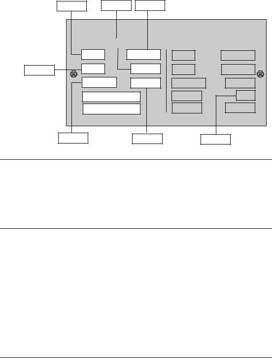
04/02 |
|
|
|
|
|
|
1 Parameters |
|
|
|
|
|
|
|
|
|
|
P0304 |
Rated motor voltage |
|
|
Min: |
10 |
|
Level: |
|
|
CStat: |
C |
Datatype: U16 |
Unit: V |
Def: |
230 |
|
1 |
|
P-Group: |
MOTOR |
Active: first confirm |
QuickComm. Yes |
Max: |
2000 |
|
|
Nominal motor voltage [V] from rating plate. Following diagram shows a typical rating plate with the locations of the relevant motor data.
P0310 |
P0305 |
P0304 |
|
|
|
|
|
|
|
3~Mot |
|
EN 60034 |
|
|
|
|
1LA7130-4AA10 |
|
||
|
No UD 0013509-0090-0031 |
TICI F |
1325 |
IP 55 |
IM B3 |
|
|
50 Hz |
230-400 V |
|
60 Hz |
|
460 V |
P0307 |
5.5kW |
19.7/11.A |
6.5kW |
|
10.9 A |
|
|
Cos ϕ 0.81 |
1455/min |
Cos ϕ 0.82 |
1755/min |
||
|
∆/Υ 220-240/380-420 V |
Υ 440-480 |
|
95.75% |
||
|
19.7-20.6/11.4-11.9 A |
11.1-11.3 A |
|
45kg |
||
P0308 |
|
P0311 |
|
|
P0309 |
|
Dependency:
Changeable only when P0010 = 1 (quick commissioning).
Note:
|
Default value is dependant on inverter rated power. |
|
|
|
|
||
P0305 |
Rated motor current |
|
|
Min: |
0.01 |
Level: |
|
|
CStat: |
C |
Datatype: Float |
Unit: A |
Def: |
3.25 |
1 |
|
P-Group: |
MOTOR |
Active: first confirm |
QuickComm. Yes |
Max: |
10000.00 |
|
Nominal motor current [A] from rating plate - see diagram in P0304.
Dependency:
Changeable only when P0010 = 1 (quick commissioning).
Depends also on P0320 (motor magnetization current).
Note:
For asynchronous motors, the maximum value is defined as the maximum inverter current.
For synchronous motors, the maximum value is defined as twice the maximum inverter current.
The minimum value is defined as 1/32 times inverter rated current (r0207).
When the relation of the nominal motor current p0305 and half of the maximal inverter current exceeds 1,5 an additional current derating is applied. This is necessary to protect the inverter from harmonic current waves.
Default value is dependant on inverter rated power.
P0307 |
Rated motor power |
|
|
Min: |
0.01 |
Level: |
|
|
CStat: |
C |
Datatype: Float |
Unit: - |
Def: |
0.75 |
1 |
|
P-Group: |
MOTOR |
Active: first confirm |
QuickComm. Yes |
Max: |
2000.00 |
|
|
|
||||||
Nominal motor power [kW/hp] from rating plate.
Dependency:
If P0100 = 1, values will be in [hp] - see diagram P0304 (rating plate).
Changeable only when P0010 = 1 (quick commissioning).
Note:
Default value is dependant on inverter rated power.
MICROMASTER 420 |
Parameter List |
6SE6400-5BA00-0BP0 |
25 |

MM420 Parameter List |
|
|
|
|
04/02 |
||
|
|
|
|
|
|
|
|
P0308 |
Rated motor cosPhi |
|
|
Min: |
0.000 |
Level: |
|
|
CStat: |
C |
Datatype: Float |
Unit: - |
Def: |
0.000 |
2 |
|
P-Group: |
MOTOR |
Active: first confirm |
QuickComm. Yes |
Max: |
1.000 |
|
Nominal motor power factor (cosPhi) from rating plate - see diagram P0304.
Dependency:
Changeable only when P0010 = 1 (quick commissioning).
Visible only when P0100 = 0 or 2, (motor power entered in [kW]).
Setting 0 causes internal calculation of value (see r0332).
P0309 |
Rated motor efficiency |
|
|
Min: |
0.0 |
Level: |
|
|
CStat: |
C |
Datatype: Float |
Unit: % |
Def: |
0.0 |
2 |
|
P-Group: |
MOTOR |
Active: first confirm |
QuickComm. Yes |
Max: |
99.9 |
|
|
|
||||||
Nominal motor efficiency in [%] from rating plate.
Dependency:
Changeable only when P0010 = 1 (quick commissioning).
Visible only when P0100 = 1, (i.e. motor power entered in [hp]).
Setting 0 causes internal calculation of value (see r0332).
Note:
P0309 = 100 % corresponds to superconducting.
Details:
See diagram in P0304 (rating plate).
P0310 |
Rated motor frequency |
|
|
Min: |
12.00 |
Level: |
|
|
CStat: |
C |
Datatype: Float |
Unit: Hz |
Def: |
50.00 |
1 |
|
P-Group: |
MOTOR |
Active: first confirm |
QuickComm. Yes |
Max: |
650.00 |
|
|
|
||||||
Nominal motor frequency [Hz] from rating plate.
Dependency:
Changeable only when P0010 = 1 (quick commissioning).
Pole pair number recalculated automatically if parameter is changed.
Details:
See diagram in P0304 (rating plate)
P0311 |
Rated motor speed |
|
|
Min: |
0 |
Level: |
|
|
CStat: |
C |
Datatype: U16 |
Unit: 1/min |
Def: |
0 |
1 |
|
P-Group: |
MOTOR |
Active: first confirm |
QuickComm. Yes |
Max: |
40000 |
|
|
|
||||||
Nominal motor speed [rpm] from rating plate.
Dependency:
Changeable only when P0010 = 1 (quick commissioning).
Setting 0 causes internal calculation of value.
Required for vector control and V/f control with speed controller.
Slip compensation in V/f control requires rated motor speed for correct operation.
Pole pair number recalculated automatically if parameter is changed.
Note:
Default value is dependant on inverter rated power.
Details:
See diagram in P0304 (rating plate)
r0313 |
Motor pole pairs |
|
Min: |
- |
Level: |
|
Datatype: U16 |
Unit: - |
Def: |
- |
3 |
|
P-Group: MOTOR |
|
Max: |
- |
|
|
|
|
Displays number of motor pole pairs that the inverter is currently using for internal calculations.
Value:
r0313 = 1 : 2-pole motor
r0313 = 2 : 4-pole motor etc.
Dependency:
Recalculated automatically when P0310 (rated motor frequency) or P0311 (rated motor speed) is changed.
26 |
MICROMASTER 420 Parameter List |
6SE6400-5BA00-0BP0 |

04/02 |
|
|
|
|
|
|
1 Parameters |
|
|
|
|
|
|
|
|
||
P0320 |
Motor magnetizing current |
|
Min: |
0.0 |
|
Level: |
||
|
CStat: |
CT |
Datatype: Float |
Unit: % |
Def: |
0.0 |
|
3 |
|
P-Group: |
MOTOR |
Active: Immediately |
QuickComm. Yes |
Max: |
99.0 |
|
|
Defines motor magnetization current in [%] relative to P0305 (rated motor current).
Dependency:
P0320 = 0:
Setting 0 causes calculation by P0340 = 1 (data entered from rating plate) or by P3900 = 1 - 3 (end of quick commissioning). The calculated value is displayed in parameter r0331.
r0330 |
Rated motor slip |
|
|
|
Min: |
- |
|
Level: |
|
|
|
|
Datatype: Float |
Unit: % |
Def: |
- |
|
3 |
|
|
P-Group: |
MOTOR |
|
|
|
Max: |
- |
|
|
|
Displays nominal motor slip in [%] relative to P0310 (rated motor frequency) and P0311 (rated motor |
|
|||||||
|
speed). |
|
|
|
|
|
|
|
|
|
|
P0310 − P0311 |
r0313 |
|
|
|
|
|
|
|
r0330 [%] = |
60 |
|
100 % |
|
|
|
|
|
|
P0310 |
|
|
|
|
|
|
||
|
|
|
|
|
|
|
|
|
|
r0331 |
Rated magnetization current |
|
Min: |
- |
|
Level: |
|||
|
|
|
Datatype: Float |
Unit: A |
Def: |
- |
|
3 |
|
|
|
|
|
|
|||||
|
P-Group: |
MOTOR |
|
|
|
Max: |
- |
|
|
Displays calculated magnetizing current of motor in [A].
r0332 |
Rated power factor |
|
Min: |
- |
Level: |
|
Datatype: Float |
Unit: - |
Def: |
- |
3 |
|
P-Group: MOTOR |
|
Max: |
- |
|
Displays power factor for motor
Dependency:
Value is calculated internally if P0308 (rated motor cosPhi) set to 0; otherwise, value entered in P0308 is displayed.
P0335 |
Motor cooling |
|
|
Min: |
0 |
Level: |
|
|
CStat: |
CT |
Datatype: U16 |
Unit: - |
Def: |
0 |
2 |
|
P-Group: |
MOTOR |
Active: first confirm |
QuickComm. Yes |
Max: |
1 |
|
|
|
||||||
Selects motor cooling system used.
Possible Settings:
0Self-cooled: Using shaft mounted fan attached to motor
1Force-cooled: Using separately powered cooling fan
Notice:
Motors of series 1LA1 and 1LA8 have an internal fan. This internal motor fan must not be confused with the fan at the end of the motor shaft.
P0340 |
Calculation of motor parameters |
|
Min: |
0 |
Level: |
||
|
CStat: |
CT |
Datatype: U16 |
Unit: - |
Def: |
0 |
2 |
|
P-Group: MOTOR |
Active: first confirm |
QuickComm. No |
Max: |
1 |
|
|
|
Calculates various motor parameters, including: |
|
|
|
|
||
|
P0344 |
Motor weight |
|
|
|
|
|
|
P0346 |
Magnetization time |
|
|
|
|
|
|
P0347 |
Demagnetization time |
|
|
|
|
|
|
P0350 |
Stator resistance |
|
|
|
|
|
|
P0611 |
Motor I2t time constant |
|
|
|
|
|
|
P1253 |
Vdc-controller output limitation |
|
|
|
|
|
|
P1316 |
Boost end frequency |
|
|
|
|
|
|
P2000 |
Reference frequency |
|
|
|
|
|
|
P2002 |
Reference current |
|
|
|
|
|
Possible Settings:
0No calculation
1Complete parameterization
Note:
|
|
This parameter is required during commissioning to optimize inverter performance. |
|
|
||||
P0344 |
Motor weight |
|
|
Min: |
1.0 |
Level: |
||
|
|
CStat: |
CUT |
Datatype: Float |
Unit: kg |
Def: |
9.4 |
3 |
|
|
P-Group: |
MOTOR |
Active: Immediately |
QuickComm. No |
Max: |
6500.0 |
|
|
|
Specifies motor weight [kg]. |
|
|
|
|
|
|
|
Note: |
This value is used in the motor thermal model. |
|
|
|
|
||
|
|
|
|
|
|
|||
|
|
It is normally calculated automatically from P0340 (motor parameters) but can also be entered manually. |
||||||
|
|
Default value is dependant on inverter rated power. |
|
|
|
|
||
MICROMASTER 420 Parameter List |
|
|
|
|
27 |
|||
6SE6400-5BA00-0BP0 |
|
|
|
|
|
|||

MM420 Parameter List |
|
|
|
|
04/02 |
||||
|
|
|
|
|
|
|
|
|
|
P0346 |
Magnetization time |
|
|
Min: |
0.000 |
Level: |
|||
|
|
|
CStat: |
CUT |
Datatype: Float |
Unit: s |
Def: |
1.000 |
3 |
|
|
|
P-Group: |
MOTOR |
Active: Immediately |
QuickComm. No |
Max: |
20.000 |
|
|
|
|
Sets magnetization time [s], i.e. waiting time between pulse enable and start of ramp-up. Motor |
|
|||||
|
|
|
magnetization builds up during this time. |
|
|
|
|
||
|
|
|
Magnetization time is normally calculated automatically from the motor data and corresponds to the rotor |
||||||
|
|
|
time constant (r0384). |
|
|
|
|
|
|
|
Note: |
If boost settings are higher than 100 %, magnetization may be reduced. |
|
|
|
||||
|
|
|
|
|
|
||||
|
Notice: |
Default value is dependant on inverter rated power. |
|
|
|
|
|||
|
An excessive reduction of this time can result in insufficient motor magnetization. |
|
|
||||||
|
|
|
|
|
|||||
P0347 |
Demagnetization time |
|
|
Min: |
0.000 |
Level: |
|||
|
|
|
CStat: |
CUT |
Datatype: Float |
Unit: s |
Def: |
1.000 |
3 |
|
|
|
P-Group: |
MOTOR |
Active: Immediately |
QuickComm. No |
Max: |
20.000 |
|
Changes time allowed after OFF2 / fault condition, before pulses can be re-enabled.
Note:
The demagnetization time is approximately 2.5 x rotor time constant (r0384) in seconds.
Default value is dependant on inverter rated power.
Notice:
Not active following a normally completed ramp-down, e.g. after OFF1, OFF3 or JOG.
Overcurrent trips will occur if the time is decreased excessively.
P0350 |
Stator resistance (line-to-line) |
|
Min: |
0.00001 |
Level: |
||
|
CStat: |
CUT |
Datatype: Float |
Unit: Ohm |
Def: |
4.0 |
2 |
|
P-Group: |
MOTOR |
Active: Immediately |
QuickComm. No |
Max: |
400.0 |
|
|
|
||||||
Stator resistance value in [Ohms] for connected motor (from line-to-line). The parameter value includes the cable resistance.
There are three ways to determine the value for this parameter: 1. Calculate using
P0340 = 1 (data entered from rating plate) or
P0010 = 1, P3900 = 1,2 or 3 (end of quick commissioning).
2.Measure using P1910 = 1 (motor data identification - value for stator resistance is overwritten).
3.Measure manually using an Ohmmeter.
Note:
Since measured line-to-line, this value may appear to be higher (up to 2 times higher) than expected. The value entered in P0350 (stator resistance) is the one obtained by the method last used.
Default value is dependant on inverter rated power.
r0370 |
Stator resistance [%] |
|
Min: |
- |
Level: |
|
Datatype: Float |
Unit: % |
Def: |
- |
4 |
|
P-Group: MOTOR |
|
Max: |
- |
|
|
|
|
Displays standardized stator resistance of motor equivalent circuit (phase value) in [%].
Note:
P0304 100 % means : Zratedmot P0305
r0372 |
|
Cable resistance [%] |
|
|
Min: |
- |
Level: |
|
|
|
|
|
Datatype: Float |
Unit: % |
Def: |
- |
4 |
|
|
P-Group: MOTOR |
|
|
|
Max: |
- |
|
|
|
Displays standardized cable resistance of motor equivalent circuit (phase value)in [%]. It is estimated to be |
||||||
|
|
20 % of the stator resistance. |
|
|
|
|
||
|
Note: |
|
|
|
|
|
|
|
|
|
100 % means : Z |
|
P0304 |
|
|
|
|
|
|
ratedmot |
|
P0305 |
|
|
|
|
r0373 |
|
Rated stator resistance [%] |
|
Min: |
- |
Level: |
||
|
|
|
|
Datatype: Float |
Unit: % |
Def: |
- |
4 |
|
|
P-Group: MOTOR |
|
|
|
Max: |
- |
|
Displays rated stator resistance of the motor equivalent circuit (phase value) in [%].
Note:
P0304 100 % means : Zratedmot P0305
28 |
MICROMASTER 420 Parameter List |
6SE6400-5BA00-0BP0 |

04/02 |
|
|
|
|
1 Parameters |
|
|
|
|
|
|
|
|
r0374 |
Rotor resistance [%] |
|
Min: |
- |
|
Level: |
|
Datatype: Float |
Unit: % |
Def: |
- |
|
4 |
|
P-Group: MOTOR |
|
Max: |
- |
|
|
Displays standardized rotor resistance of the motor equivalent circuit (phase value) in [%].
Note:
P0304 100 % means : Zratedmot P0305
r0376 |
Rated rotor resistance [%] |
|
Min: |
- |
Level: |
|
Datatype: Float |
Unit: % |
Def: |
- |
4 |
|
P-Group: MOTOR |
|
Max: |
- |
|
Displays rated rotor resistance of the motor equivalent circuit (phase value) in [%].
Note:
P0304 100 % means : Zratedmot P0305
r0377 |
Total leakage reactance [%] |
|
Min: |
- |
Level: |
|
Datatype: Float |
Unit: % |
Def: |
- |
4 |
|
|
||||
|
P-Group: MOTOR |
|
Max: |
- |
|
Displays standardized total leakage reactance of the motor equivalent circuit (phase value) in [%].
Note:
P0304 100 % means : Zratedmot P0305
r0382 |
Main reactance [%] |
|
Min: |
- |
Level: |
|
Datatype: Float |
Unit: % |
Def: |
- |
4 |
|
|
||||
|
P-Group: MOTOR |
|
Max: |
- |
|
Displays standardized main reactance of the motor equivalent circuit (phase value) in [%].
Note:
P0304 100 % means : Zratedmot P0305
r0384 |
|
Rotor time constant |
|
|
Min: |
- |
Level: |
|
|
|
Datatype: Float |
Unit: ms |
Def: |
- |
3 |
|
|
|
|
||||
|
|
P-Group: MOTOR |
|
|
Max: |
- |
|
|
|
Displays calculated rotor time constant [ms]. |
|
|
|
|
|
r0386 |
|
Total leakage time constant |
|
Min: |
- |
Level: |
|
|
|
|
Datatype: Float |
Unit: ms |
Def: |
- |
4 |
|
|
P-Group: MOTOR |
|
|
Max: |
- |
|
|
|
Displays total leakage time constant of motor. |
|
|
|
|
|
r0395 |
|
CO: Total stator resistance [%] |
|
Min: |
- |
Level: |
|
|
|
|
Datatype: Float |
Unit: % |
Def: |
- |
3 |
|
|
|
|
||||
|
|
P-Group: MOTOR |
|
|
Max: |
- |
|
|
|
Displays stator resistance of motor as [%] of combined stator/cable resistance. |
|
|
|||
|
Note: |
|
|
|
|
|
|
|
|
100 % means : Z |
P0304 |
|
|
|
|
|
|
ratedmot |
P0305 |
|
|
|
|
MICROMASTER 420 |
Parameter List |
6SE6400-5BA00-0BP0 |
29 |

MM420 Parameter List |
|
|
|
|
04/02 |
||
|
|
|
|
|
|
||
P0610 |
Motor I2t temperature reaction |
|
Min: |
0 |
Level: |
||
|
CStat: |
CT |
Datatype: U16 |
Unit: - |
Def: |
2 |
3 |
|
P-Group: |
MOTOR |
Active: first confirm |
QuickComm. No |
Max: |
2 |
|
Defines reaction when motor I2t reaches warning threshold.
Possible Settings:
0No reaction, warning only
1Warning and Imax reduction (results in reduced output frequency)
2 |
Warning and trip (F0011) |
Dependency: |
|
Trip level = P0614 (motor I2t overload warning level) * 110 %
Note:
The purpose of motor I²t is to calculate or measure the motor temperature and disable the inverter if the motor is in danger of overheating.
The motor temperature will be dependent on many factors, including the size of the motor, the ambient temperature, the previous history of the loading of the motor, and of course, the load current. (The square of the current actually determines the heating of the motor and the temperature rises with time - hence I²t).
Because most motors are cooled by built in fans running at motor speed, the speed of the motor is also important. Clearly a motor running at high current (maybe due to boost) and a low speed, will overheat more quickly than one running at 50 or 60 Hz, full load. The MM4 take account of these factors.
The drives also include inverter I²t protection (i.e. overheating protection, see P0290) in order to protect the units themselves. This operates independently of the motor I²t, and is not described here.
I²t operation:
The measured motor current (r0027) is compared with the rated motor current (P0305), and other motor parameters (P0304, P0307, etc.), and the temperature of the motor calculated, a calculation which also includes the output frequency (motor speed) to account for fan cooling. If parameter P0335 is changed to indicate a forced cooled motor, the calculation is modified accordingly.
Where parameters are not entered by the user, such as P0344 (motor weight), a calculated value will be used based on a Siemens motor. If required, the motor time constant can be adjusted using P0611, in effect overwriting the calculated value.
The resulting temperature is displayed in % of maximum temperature in r0034. When this value reaches the value set in P0614 (default 100%), a warning A0511 occurs. If no action is taken and the temperature reaches 110%, then the inverter trips, showing F0011. The reaction to the warning can be changed from this default using P0610; for example, the drive can react as though a current limit has occurred, or a fault forced immediately. The warning level of P0614 can also be adjusted to raise and lower the warning or trip level as required.
Parameter r0034 is particularly useful to monitor if the calculated motor temperature is rising excessively.
P0611 |
Motor I2t time constant |
|
|
Min: |
0 |
Level: |
|
|
CStat: |
CT |
Datatype: U16 |
Unit: s |
Def: |
100 |
2 |
|
P-Group: |
MOTOR |
Active: Immediately |
QuickComm. No |
Max: |
16000 |
|
|
|
||||||
Defines motor thermal time constant and is calculated automatically from the motor data (see P0340).
Notice:
A larger number increases the time taken for the calculated motor temperature to change. Default value is dependant on inverter rated power.
P0614 |
Motor I2t overload warning level |
|
Min: |
0.0 |
Level: |
||
|
CStat: |
CUT |
Datatype: Float |
Unit: % |
Def: |
100.0 |
2 |
|
P-Group: |
MOTOR |
Active: first confirm |
QuickComm. No |
Max: |
400.0 |
|
|
|
||||||
Defines the [%] value at which alarm A0511 (motor overtemperature) is generated.
Motor I2t calculation is used to estimate a maximum tolerable period (i.e. without overheating) for motor overload. The I2t calculation value is deemed = 100 % when this maximum tolerable period is reached (see r0034).
Dependency:
A motor over-temperature trip (F0011) is produced at 110 % of this level.
P0640 |
Motor overload factor [%] |
|
Min: |
10.0 |
Level: |
||
|
CStat: |
CUT |
Datatype: Float |
Unit: % |
Def: |
150.0 |
2 |
|
P-Group: |
MOTOR |
Active: Immediately |
QuickComm. Yes |
Max: |
400.0 |
|
|
|
||||||
Defines motor overload current limit in [%] relative to P0305 (rated motor current).
Dependency:
Limited to maximum inverter current or to 400 % of rated motor current (P0305), whichever is the lower.
Details:
See function diagram for current limitation.
30 |
MICROMASTER 420 Parameter List |
6SE6400-5BA00-0BP0 |
Loading...