


Sharp GB-X24JR, GU-X24JR, GB-X36JR, GB-X18JR, GU-X36JR Manual [bg]
...SPLIT TYPE
ROOM AIR CONDITIONER
INSTALLATION AND OPERATION MANUAL
CONDIZIONATORE D'ARIA
DA CAMERA TIPO SPLIT
MANUALE PER L'INSTALLAZIONE E IL FUNZIONAMENTO
AR CONDICIONADO DE SALA DE DUAS UNIDADES
MANUAL DE OPERAÇÃO E DE INSTALAÇÄO
PORTUGUÊS ITALIANO ENGLISH
INDOOR UNIT
GB-X18JR GB-X24JR GB-X36JR
OUTDOOR UNIT
GU-X18JR GU-X24JR GU-X36JR
|
|
|
|
|
|
|
|
|
|
|
|
|
|
|
|
GREE_duct_cov_1022.indd 1 |
|
08.10.27 3:30:13 PM |
|
|
|
||
|
|
||||||
|
|
|
|
|
|
|
|
Attention: Your product is marked with this symbol. It means that used electrical and electronic products should not be mixed with general household waste. There is a separate collection system for these products.
Pb
A. Information on Disposal for Users (private households)
1. In the European Union
Attention: If you want to dispose of this equipment, please do not use the ordinary dust bin!
Used electrical and electronic equipment must be treated separately and in accordance with legislation that requires proper treatment, recovery and recycling of used electrical and electronic equipment.
Following the implementation by member states, private households within the EU states may return their used electrical and electronic equipment to designated collection facilities free of charge*. In some countries* your local retailer may also take back your old product free of charge if you purchase a similar new one.
*) Please contact your local authority for further details.
If your used electrical or electronic equipment has batteries or accumulators, please dispose of these separately beforehand according to local requirements.
By disposing of this product correctly you will help ensure that the waste undergoes the necessary treatment, recovery and recycling and thus prevent potential negative effects on the environment and human health which could otherwise arise due to inappropriate waste handling.
2. In other Countries outside the EU
If you wish to discard this product, please contact your local authorities and ask for the correct method of disposal.
For Switzerland: Used electrical or electronic equipment can be returned free of charge to the dealer, even if you don’t purchase a new product. Further collection facilities are listed on the homepage of www.swico.ch or www.sens.ch.
B. Information on Disposal for Business Users.
1. In the European Union
If the product is used for business purposes and you want to discard it:
Please contact your SHARP dealer who will inform you about the take-back of the product. You might be charged for the costs arising from take-back and recycling. Small products (and small amounts) might be taken back by your local collection facilities.
For Spain: Please contact the established collection system or your local authority for take-back of your used products.
2. In other Countries outside the EU
If you wish to discard of this product, please contact your local authorities and ask for the correct method of disposal.
The battery supplied with this product contains traces of Lead.
For EU: The crossed-out wheeled bin implies that used batteries should not be put to the general household waste!
There is a separate collection system for used batteries, to allow proper treatment and recycling in accordance with legislation. Please contact your local authority for details on the collection and recycling schemes.
For Switzerland: The used battery is to be returned to the selling point.
For other non-EU countries: Please contact your local authority for correct method of disposal of the used battery.
EN
|
|
|
|
|
|
|
|
|
|
|
|
|
|
|
|
GREE_duct_cov_1022.indd 2 |
|
08.10.27 3:30:14 PM |
|
|
|
||
|
|
||||||
|
|
|
|
|
|
|
|
ENGLISH
CONTENTS
Operating Instructions
• |
Important safety instructions................................................... |
E-2 |
• |
Wire controller operation......................................................... |
E-3 |
|
ON/OFF............................................................................... |
E-4 |
|
Fan Control.......................................................................... |
E-4 |
|
Temperature setting ............................................................ |
E-4 |
|
Sleep function setting.......................................................... |
E-5 |
|
Operating mode setting....................................................... |
E-5 |
|
Timer setting........................................................................ |
E-6 |
|
SAVE setting ....................................................................... |
E-6 |
|
Display of outdoor temperature........................................... |
E-7 |
|
Memory function setting....................................................... |
E-7 |
|
Room temperature sensor setting....................................... |
E-7 |
|
Failure display..................................................................... |
E-8 |
• |
Remote Controller operation................................................... |
E-9 |
|
Loading Batteries................................................................. |
E-9 |
|
Cool mode operation......................................................... |
E-10 |
|
Heat mode operation ........................................................ |
E-10 |
|
Dry mode operation........................................................... |
E-11 |
|
Fan mode operation.......................................................... |
E-11 |
• |
Unit Function......................................................................... |
E-12 |
Installation Instructions
• |
Installation dimensions.......................................................... |
E-13 |
• |
Installation of indoor unit ...................................................... |
E-16 |
• |
Installation of rectangular air pipe......................................... |
E-17 |
• |
Installation of drainage pipeline............................................. |
E-18 |
• |
Installation of refrigerant pipe................................................ |
E-18 |
• |
Position and method of installing wire controller................... |
E-21 |
• |
Electrical installation.............................................................. |
E-22 |
• |
Troubleshooting.................................................................... |
E-24 |
• Maintenance ......................................................................... |
E-25 |
|
• Appendix .............................................................................. |
E-25 |
|
Please read this manual carefully before using the product. This manual should be kept in a safe place for handy reference.
E-
ENGLISH
|
|
|
|
|
|
|
|
|
|
|
|
|
|
|
|
GREE_duct_eng_1022.indd 1 |
|
08.10.27 3:32:03 PM |
|
|
|
||
|
|
||||||
|
|
|
|
|
|
|
|
IMPORTANT SAFETY INSTRUCTIONS
WARNINGS FOR USE
1Do not pull or deform the power supply cord. Pulling and misuse of the power supply cord can result in damage to the unit and cause electrical shock.
2Be careful not to expose your body directly to the outlet air for a long time. It may affect your physical conditions.
3When using the air conditioner for infants, children, elderly, bedridden, or disabled people make sure the room temperature is suitable for those in the room.
4Never insert objects into the unit. Inserting objects can result in injury due to the high speed rotation of internal fans.
5Ground the air conditioner without fail. Do not connect the grounding wire to gas pipe, water pipe, lightning rod or telephone grounding wire. Incomplete grounding may cause electric shock.
6If anything is abnormal with the air conditioner (ex. a burning smell), stop the operation immediately and turn the circuit breaker OFF.
7The appliance shall be installed in accordance with national wiring regulations. Improper cable connection can cause the power supply cord, plug and the electrical outlet to overheat and cause fire.
8If the supply cord is damaged, it must be replaced by the manufacturer or its service agent or a similarly qualified person in order to avoid a hazard. Use only the manufacture-specified power cord for replacement.
CAUTIONS FOR USE
1Open a window or door periodically to ventilate the room, especially when using gas appliances. Insufficient ventilation may cause oxygen shortage.
2Do not operate the buttons with wet hand. It may cause electric shock.
3For safety, turn the circuit breaker off when not using the unit for an extended period of time.
4Check the outdoor unit mounting rack periodically for wear and to make sure it is firmly in place.
5Do not put anything on the outdoor unit nor step on it. The object or the person may fall down or drop, causing injury.
6This unit is designed for residential use. Do not use for other applications such as in a kennel or greenhouse to raise animals or grow plants.
7Do not place a vessel with water on the unit. If water penetrates into the unit, electrical insulations may deteriorate and cause electric shock.
8Do not block the air inlets nor outlets of the unit. It may cause insufficient performance or troubles.
9Be sure to stop the operation and turn the circuit breaker off before performing any maintenance or cleaning. A fan is rotating inside the unit and you may get injured.
10Do not splash or pour water directly on the unit. Water can cause electrical shock or equipment damage.
11This appliance is not intended for use by young children or infirm persons without supervision.
Young children should be supervised to ensure that they do not play with the appliance.
12Once started, the air conditioner shall not be stopped at least after 5 minutes or longer; otherwise the oil return to compressor may be affected.
WARNINGS FOR INSTALLATION/REMOVAL/REPAIR
•Do not attempt to install/remove/repair the unit by yourself. Incorrect work will cause electric shock, water leak, fire etc. Consult your dealer or other qualified service personnel for the installation/removal/repair of the unit.
•This unit shall be used in offices, restaurants, residences or similar places.
•Please install at a place strong enough to support the weight of air conditioner unit. If not, the air conditioner unit might fall down and cause human injury or death.
•The appliance shall not be installed in the laundry.
CAUTIONS FOR LOCATION/INSTALLATION
•Make sure to connect the air conditioner to power supply of the rated voltage and frequency.
Use of a power supply with improper voltage and frequency can result in equipment damage and possible fire.
•Do not install the unit in a place where inflammable gas may leak. It may cause fire.
Install the unit in a place with minimal dust, fumes and moisture in the air.
•Arrange the drain hose to ensure smooth drainage. Insufficient drainage may cause wetting of the room, furniture etc.
•Make sure an earth leakage breaker or a circuit breaker is installed, depending on the installation location, to avoid electrical shock.
•Before use, please check and confirm if the cables, drainage pipes and pipelines are correctly connected, hence to eliminate the risk of water leakage, refrigerant leakage, electric shock or fire.
•Please do not expose the air conditioner unit directly under corrosive environment with water or moisture.
•After electrical installation, the air conditioner unit shall be energized for electrical leakage test.(Operating by professinal)
•An all-pole disconnection switch having a contact separation of at least 3mm in all poles should be connected in fixed wiring.
•The temperature of refrigerant circuit will be high, keep the interconnection cable away from the copper pipe.
E-
|
|
|
|
|
|
|
|
|
|
|
|
|
|
|
|
GREE_duct_eng_1022.indd 2 |
|
08.10.27 3:32:03 PM |
|
|
|
||
|
|
||||||
|
|
|
|
|
|
|
|
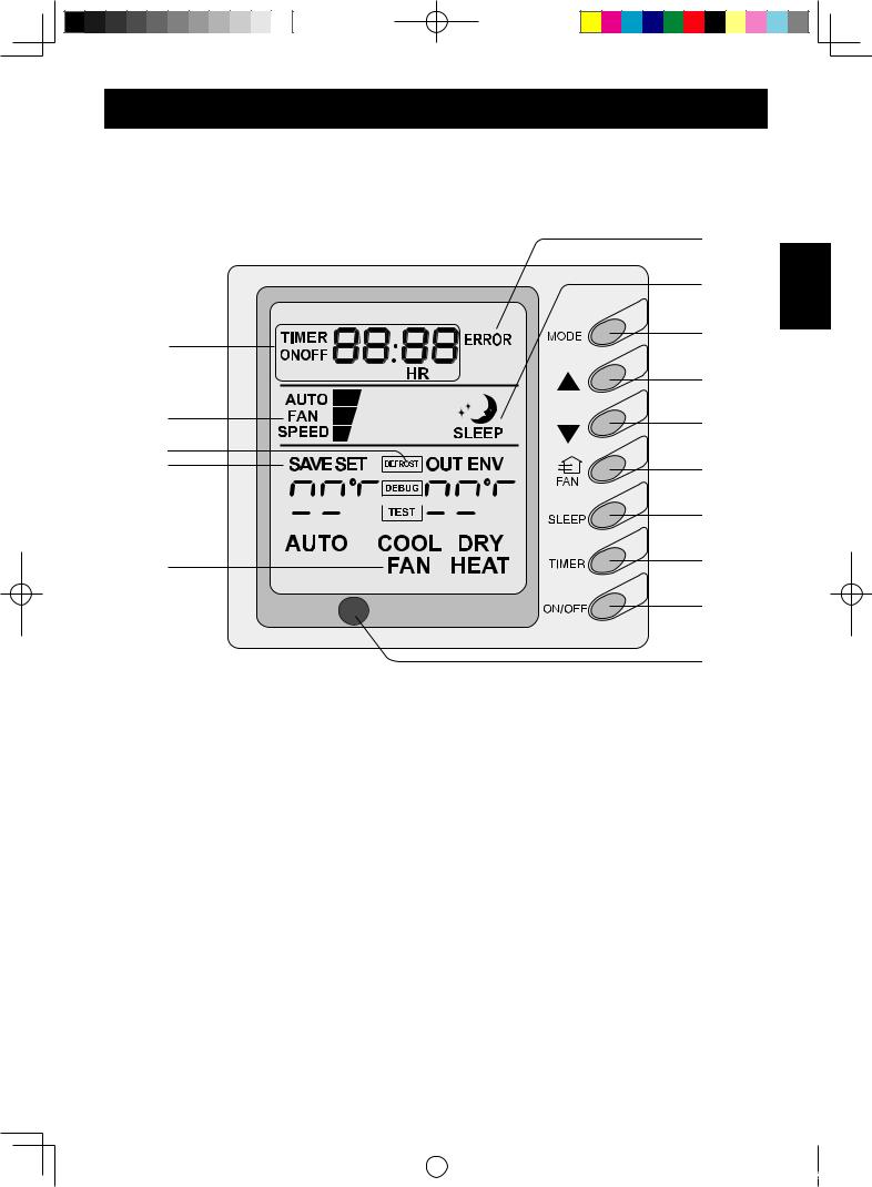
WIRE CONTROLLER OPERATION
WARNING
•Never install the wire controller in a place where is water leakage.
•Avoid bumping, throwing, tossing or frequently opening the wire controller.
1
2
3
4
5 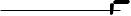


 6
6 
7
1 |
TIMER display |
|
|
2 |
Fan speed display (Auto, High, Medium, Low) |
3 |
DEFROST display |
4 |
SAVE display |
5 |
Set temperature display |
6 |
Ambient temperature display |
7 |
Mode (cool, dry, fan, heat, auto) display |
8 |
Failure display |
9 |
SLEEP display |
10 |
MODE button |
11 |
Temperature setting button (for temperature rise) |
12 |
Temperature setting button (for temperature drop) |
13 |
FAN button |
14 |
SLEEP button (outdoor temperature check) |
15 |
TIMER button |
16 |
ON/OFF button |
17 |
Receiver window |
E-
8
9
10
11
12
13
14
15
16
17
ENGLISH
|
|
|
|
|
|
|
|
|
|
|
|
|
|
|
|
GREE_duct_eng_1022.indd 3 |
|
08.10.27 3:32:03 PM |
|
|
|
||
|
|
||||||
|
|
|
|
|
|
|
|
WIRE CONTROLLER OPERATION
ON/OFF
• Press the ON/OFF button, the unit will start up.
• Press the ON/OFF button again, the unit will turn off.
Fan control (the figures show the relevant display areas)
• Press FAN button to change fan speed.
 Low
Low  Medium
  Hight
Hight  Auto
Auto
In the DRY mode, the fan speed will be automatically set to Low.
Temperature setting
• Press the temperature setting button ( |
) to rise the |
set temperature. |
) to drop the |
Press the temperature setting button ( |
|
set temperature. |
|
(Press the buttons once, the temperature setting will change by 1 °C).
NOTE:
Button lock function
When the ( ) and ( ) buttons are pressed simultaneously for 5 seconds, the set temperature indicating area will display “EE” and all buttons response will be shut off.
To cancel the button lock function, press the two buttons simultaneously for 5 second again.
Range of temperature setting:
•Heat: 16 °C~30 °C
•Cool: 16 °C~30 °C
•Dry: 16 °C~30 °C
•Fan: No temperature setting function
E-
|
|
|
|
|
|
|
|
|
|
|
|
|
|
|
|
GREE_duct_eng_1022.indd 4 |
|
08.10.27 3:32:04 PM |
|
|
|
||
|
|
||||||
|
|
|
|
|
|
|
|
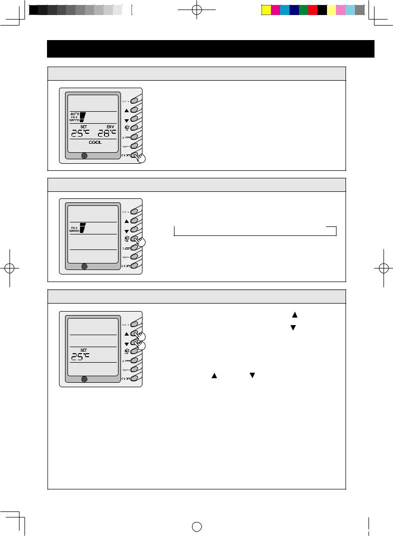
Sleep function setting
•COOL or DRY mode
One hour after the SLEEP button is pressed, the set temperature rises by 1˚C, and after 2 hours the set temperature rises by additional 1˚C .
• HEAT mode
One hour after the SLEEP button is pressed, the set temperature drops by 1˚C, and after 2 hours the set temperature drops by additional 1˚C .
• Sleep function cannot be set during Fan mode.
ENGLISH
Operating mode setting
• Press the MODE button to select the operation mode
|
COOL |
|
DRY |
|
FAN |
HEAT |
AUTO |
|
|
|
|
|
|||||
|
|
|
|
|
|
|
|
|
COOL mode
The set temperature must be lower than the room temperature. If the set temperature is higher than the room temperature, the unit will not produce cooling effect but will only operate under Fan mode.
DRY mode
Fan motor will run at low fan speed in a specific temperature range. The dehumidifying effect of this mode is better than that of the COOL mode and saves more energy.
HEAT mode
The set temperature must be higher than the room temperature. If the set temperature is lower than the room temperature, the heating function will not be started.
AUTO mode
The unit will adjust its operating mode automatically according to the ambient temperature.
In heating operation, the outdoor temperature is low and the humidity is high, frost will produce on the outdoor unit. The heating efficiency will be decreased.
When frosting occurs, the unit will automatically start to defrost, and “DEFROST” will be displayed.
E-
|
|
|
|
|
|
|
|
|
|
|
|
|
|
|
|
GREE_duct_eng_1022.indd 5 |
|
08.10.27 3:32:05 PM |
|
|
|
||
|
|
||||||
|
|
|
|
|
|
|
|

WIRE CONTROLLER OPERATION
Timer setting
•When the unit is not operating, timer start can be set. When the unit is operating, timer shutoff can be set. The range of timer setting is between 0.5 to 24 hours.
1 Press the TIMER button to enter the timer set status.
The word “TIMER” will flash on the display.
2 Press ( ) or ( ) button to increase or decrease the set time.
3 Press the TIMER button again. The timer will go into effect. The unit will start to count the time passed.
To cancel timer setting, press the TIMER button.
SAVE setting
•When the unit is shut off, press the FAN button and the ( ) button simultaneously for 5 seconds to activate the SAVE setting menu.
The “SAVE” and “COOL” will be displayed (For the first setting, the initial value will be displayed: 26) .
The lower limit of temperature will be displayed on the set temperature area and the temperature value will be flashed. Set the lower limit of cooling temperature to press the ( ) button or the ( ) button. (rang of setting : 16-30).
Press the ON/OFF button to confirm the setting. Use the ( ) button or the ( ) button to set the upper limit of temperature and the temperature value will flash on the ambient temperature area (OUT ENV area). (rang of setting : 16-30).
Press the ON/OFF button to confirm the setting. Take care that the upper limit temperature must be higher than the set lower limit temperature; Otherwise the system will regard the higher temperature as the upper limit temperature and the lower one as the lower limit temperature.
Press the MODE button to complete the SAVE setting for the modes of cooling and dehumidifying and turn to the SAVE setting for the heating mode. The “SAVE” and “HEAT” will be displayed. After setting is completed, press the FAN button and the ( ) button simultaneously for 5 seconds to exit the SAVE setting. After the SAVE setting interface is activated, the system will exit the interface if there is no any operation within 20 seconds after the last button input, and the normal shutoff status interface will be displayed. After the above settings are completed, the system will display “SAVE”. The set temperature will not exceed the temperature range of the SAVE setting. For example, the lower cooling limit is set to 23°C and the upper cooling limit is set to 27°C, so the cooling temperature can only be selected from the range of 23°C to 27°C by using the remote controller or the wire controller. If the upper limit temperature is the same as the lower limit temperature, the system can only operate at this temperature under corresponding mode.
To cancel the SAVE setting, press the FAN button and the ( ) button simultaneously for 5 seconds when the unit is shut off. The value set before will not be cleared but as the initial set temperature for the next energy saving setting.
After the unit is disconnected to power supply, the SAVE setting will be memorised. The setting still functions when the unit is connected to power supply again. If the SAVE mode is set, the sleep mode and the auto mode will be invalidated.
E-
|
|
|
|
|
|
|
|
|
|
|
|
|
|
|
|
GREE_duct_eng_1022.indd 6 |
|
08.10.27 3:32:05 PM |
|
|
|
||
|
|
||||||
|
|
|
|
|
|
|
|
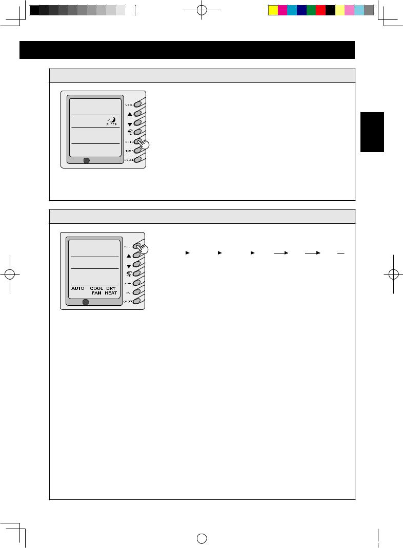
Display of outdoor temperature
•Under normal conditions, the “ENV” and the room temperature are displayed. Press the SLEEP button for 5 seconds. The LCD will display “OUT ENV”. The outdoor temperature will show in the display for 10 seconds, and then return to the room temperature.
ENGLISH
Memory function setting
•When the unit is shut off, press the MODE button for 10 seconds to switch set values so as to decide if the unit operating status or shut off status is memorized after a power fail.
If the set temperature area displays "01", it means the unit operating status or shut off status shall be memorized after a power fail; "02" means the operating status or shut off status will not be memorized.
Press the ON/OFF button to store the set value and exit the setting.
Room Temperature Sensor Setting
•When the unit is shut off, press the FAN button and the SLEEP button simultaneously to activate the debug menu.
The LCD will display “DEBUG”.
Under the debug mode, press the MODE button so as to display “01” on the set temperature area (at the left of “DEBUG”). The OUT ENV area (at the right of “DEBUG”) displays setting status.
Press the ( ) button or the ( ) button to select from the following two settings:
The room temperature is measured at the air intake (The
OUT ENV area displays 01).
The room temperature is measured at the wire controller (The OUT ENV area displays 02). The default room temperature sensor is set at the air intake.
E-
|
|
|
|
|
|
|
|
|
|
|
|
|
|
|
|
GREE_duct_eng_1022.indd 7 |
|
08.10.27 3:32:06 PM |
|
|
|
||
|
|
||||||
|
|
|
|
|
|
|
|
WIRE CONTROLLER OPERATION
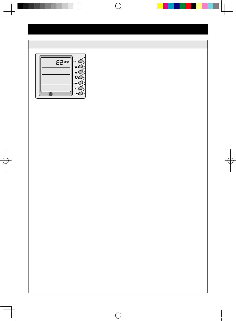
Failure Display
•When there is failure in the unit operation, the “ERROR” will flash on the display of the wire controller and the error code will also be displayed. When there are multiple failures, the error codes will be displayed one after one on the wire controller. The two digits indicate the detailed the error code.
The Error Codes Definitions are as Follows:
Error code |
Fault |
E0 |
Pump Failure |
E1 |
Compressor High Pressure Protection |
E2 |
Indoor Frost-Proof Protection |
E3 |
Compressor Low Pressure Protection |
E4 |
Compressor Exhaust High Temperature Protection |
E5 |
Compressor Overheat And Inverter Driving Protection |
E6 |
Communications Failure |
|
|
E8 |
Indoor Fan Protection |
E9 |
Full Water Protection |
FF |
Connected control communications Failure |
F0 |
Failure of Indoor Room Sensor at Air Intake |
F1 |
Failure of Evaporator Temp. Sensor |
F2 |
Failure of Condenser Temp. Sensor |
F3 |
Failure of Outdoor Ambient Sensor |
F4 |
Failure of Exhaust Temp. Sensor |
F5 |
Failure of Indoor Room Sensor at Wire Controller |
EE |
Buttons are locked (not failure) |
•E5 : Material malfunction will be showed by the indicator light on the mother board of outdoor unit.
E-
|
|
|
|
|
|
|
|
|
|
|
|
|
|
|
|
GREE_duct_eng_1022.indd 8 |
|
08.10.27 3:32:06 PM |
|
|
|
||
|
|
||||||
|
|
|
|
|
|
|
|
REMOTE CONTROLLER OPERATION |
|
|
Precautions: |
|
|
• Point the remote controller towards the receiver window on the wire controller and press the |
|
|
desired button. |
|
|
• Ensure there is no obstacle between the remote controller and the receiver window of the |
|
|
wire controller. |
|
|
• The remote control can send signals from up to 8 metres away. |
ENGLISH |
|
• Never drop or throw at will the remote controller. |
|
|
• Never let any liquid enter the remote controller. Avoid direct sunshine over the remote |
|
|
controller. Do not place the remote controller in an extremely hot place. |
|
|
• SWING button is invalid for this unit. |
|
|
FAN button |
|
|
Press to set fan speed. |
|
|
|
Receiver window |
|
TEMP. button |
|
|
Press to set suitable |
|
|
TEMP. |
|
|
MODE button |
|
|
Press to set operation |
|
|
mode. |
ON/OFF button |
|
|
|
|
|
Press to start or stop |
|
|
operation. |
|
Loading Batteries
ACL 
•After batteries are installed, the display shall display icons and letter codes of all functions.
•The life of batteries is about 1 year.
•Do not mix new and old batteries or mix different types of batteries in usage
•If the remote controller shall not be used for a long time, take out the batteries to avoid liquid leakage and any subsequent failure.
•Load two “R03(AAA)” batteries. (Accessories)
E-
|
|
|
|
|
|
|
|
|
|
|
|
|
|
|
|
GREE_duct_eng_1022.indd 9 |
|
08.10.27 3:32:07 PM |
|
|
|
||
|
|
||||||
|
|
|
|
|
|
|
|
REMOTE CONTROLLER OPERATION
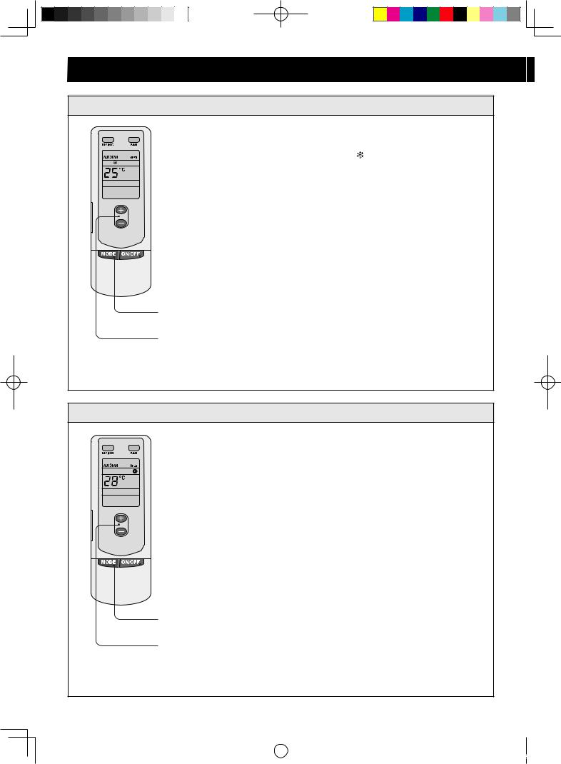
COOL mode operation
1 |
Press the ON/OFF button. |
2 |
Press the MODE button to select |
|
“COOL( ) ” mode. |
3 |
Press the Temperature button to set |
|
the desired temperature. |
 1
1
2
3
HEAT mode operation
 1
1
2
3
1Press the ON/OFF button.
2Press the MODE button to select “HEAT(  )” mode.
3Press the Temperature button to set desired temperature.
In the heating mode, the unit has the functions of preventing cold air supply and supplying remaining heat. After the startup of the compressor, the indoor fan shall start operation when the evaporator temperature is high or equals 35˚C or after the unit has be started for 45 seconds, so as to prevent cold air flow blowing out of the unit. After the stop of the compressor, the indoor fan will rotate for 120 seconds.
E-10
|
|
|
|
|
|
|
|
|
|
|
|
|
|
|
|
GREE_duct_eng_1022.indd 10 |
|
08.10.27 3:32:07 PM |
|
|
|
||
|
|
||||||
|
|
|
|
|
|
|
|
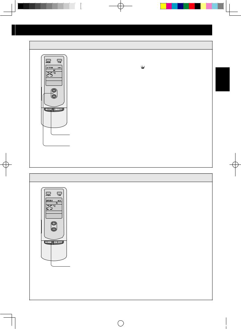
DRY mode operation
1 |
Press the ON/OFF button. |
2 |
Press the MODE button to select “DRY |
|
( )” mode. |
3 |
Press the Temperature button to set |
|
desired temperature. |
 1
1
2
3
FAN mode operation
1 Press the ON/OFF button.
2 Press the MODE button to select “FAN(
 )” mode.
3 Press the FAN button to select from high, medium and low speed.
ENGLISH
 1
1
2
E-11
|
|
|
|
|
|
|
|
|
|
|
|
|
|
|
|
GREE_duct_eng_1022.indd 11 |
|
08.10.27 3:32:08 PM |
|
|
|
||
|
|
||||||
|
|
|
|
|
|
|
|
UNIT FUNCTION
1. Setting of Double Room Temperature |
|
Sensors |
|
This series of ducted air-conditioning |
|
unit has two room temperature sensors. |
|
One is located at the air intake of the |
|
indoor unit and the other one is located |
Room temperature sensor A |
inside the wire controller. |
|
User can select one from the two room |
|
temperature sensors on the basis of the |
|
engineering requirement (Refer to the |
Room temperature sensor B |
section of wire controller instructions |
|
for detailed operation. The default room |
|
temperature sensor is the one located |
|
at air intake.) |
|
2.Checking of Outdoor Temperature
The outdoor temperature can be checked on the wire controller. (Refer to the section of wire controller instructions for detailed operation.)
Outdoor side |
Indoor side |
Outdoor sensor
3.The head of delivery of the condensate drainage pump can reach 1.1m, so that the engineering installation is very convenient and prompt.
No Pump |
GB-X18JR |
Pump |
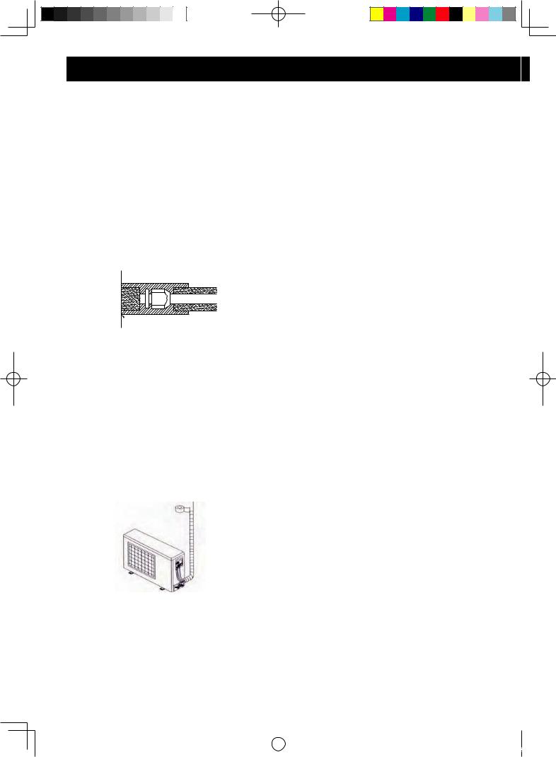
GB-X24JR/GB-X36JR |
|
|
Head of delivery of pump is 1100mm
E-12
|
|
|
|
|
|
|
|
|
|
|
|
|
|
|
|
GREE_duct_eng_1022.indd 12 |
|
08.10.27 3:32:08 PM |
|
|
|
||
|
|
||||||
|
|
|
|
|
|
|
|
INSTRUCTIONS OF UNIT INSTALLATION
Installation dimensions
Indoor unit
GB-X18JR
A
G
F
B
|
|
C |
Electric Box |
Liquid Pipe Gas Pipe |
D |
Air Intake |
H |
|
J I |
|
|
Air Intake |
Drainage Pipe |
E |
|
GB-X24JR/GB-X36JR
GB-X24JR |
G |
|
|
GB-X36JR |
|
|
|
|
|||
|
|
|
|
|
G |
|
|
|
|
||
|
|
|
|
|
|
|
|
|
|
|
|
|
|
|
|
|
|
|
|
|
|
|
|
|
|
|
|
|
|
|
|
|
|
|
|
|
|
|
|
|
|
|
|
|
|
|
|
|
|
|
|
|
|
|
|
|
|
|
|
|
|
|
|
|
|
|
|
|
|
|
|
A |
A |
F B |
F B |
C |
C |
D |
D |
E |
E |
Electric Box
Air Intake
I |
H J |
|
Drainage Pipe |
Gas Pipe |
Liquid Pipe |
|
|
|
|
|
|
|
|
|
|
|
|
|
Length unit: mm |
|
|
|
|
|
|
|
|
|
|
|
|
|
|
|
|
Item |
A |
B |
C |
D |
E |
F |
G |
H |
I |
J |
Connecting |
Connecting |
|
Drainage Pipe |
Model |
Pipe |
Pipe |
|
(Outer Diameter x |
||||||||||
|
|
|
|
|
|
|
|
|
|
(Liquid Pipe) |
(Gas Pipe) |
|
Wall Thickness) |
|
GB-X18JR |
932 |
430 |
738 |
894 |
1012 |
736 |
738 |
125 |
207 |
266 |
1/4" |
1/2" |
|
ø30 x 1.5 |
|
|
|
|
|
|
|
|
|
|
|
|
|
|
|
GB-X24JR |
1101 |
515 |
820 |
1159 |
1270 |
504 |
1002 |
160 |
235 |
268 |
3/8" |
5/8" |
|
ø20 x 1.5 |
|
|
|
|
|
|
|
|
|
|
|
|
|
|
|
GB-X36JR |
1011 |
748 |
820 |
1115 |
1251 |
744 |
980 |
160 |
231 |
290 |
1/2" |
3/4" |
|
ø20 x 1.5 |
|
|
|
|
|
|
|
|
|
|
|
|
|
|
|
E-13
ENGLISH
|
|
|
|
|
|
|
|
|
|
|
|
|
|
|
|
GREE_duct_eng_1022.indd 13 |
|
08.10.27 3:32:09 PM |
|
|
|
||
|
|
||||||
|
|
|
|
|
|
|
|
INSTRUCTIONS OF UNIT INSTALLATION
GB-X18JR
Nut with
Washer
Nut Spring
Washer
MIN.250 |
|
MIN.250 |
||
|
|
|
||
|
|
|
|
|
GB-X24JR/GB-X36JR
Nut with |
Nut Spring Washer |
|
Washer |
||
|
|
MIN.2500 |
MIN.250 |
MIN.250 |
|
Length unit:mm
Warning:
The height of installation for the indoor unit should be 2.5m above.
E-14
|
|
|
|
|
|
|
|
|
|
|
|
|
|
|
|
GREE_duct_eng_1022.indd 14 |
|
08.10.27 3:32:09 PM |
|
|
|
||
|
|
||||||
|
|
|
|
|
|
|
|

Outdoor Unit
|
|
|
|
|
C |
E |
|
|
|
|
|
|
|
|
D |
|
|
|
|
|
|
|
A |
|
|
|
|
B |
|
|
|
|
|
|
|
|
length unit:mm |
|
|
Item |
A |
B |
C |
D |
E |
|
|
Model |
|
|
|||||
|
|
|
|
|
|
|
|
GU-X18JR |
|
848 |
320 |
540 |
548 |
286 |
|
GU-X24JR |
|
913 |
378 |
680 |
548 |
340 |
|
GU-X36JR |
1032 |
412 |
1250 |
572 |
378 |
|
|
|
|
|
|
|
|
MIN.1000 |
|
MIN.500 |
MIN.500 |
|
MIN.500 |
|
|
MIN.2000 |
MIN.500 |
|
|
|
|
||||
|
|
|
|
|
|
||
|
MIN.2000 |
|
|
|
|
|
|
ENGLISH
Precautions on installation of outdoor unit
To ensure the unit in proper function, selection of installation location must be in accordance with following principles:
•Outdoor unit shall be installed so that the air discharged by outdoor unit will not return and that sufficient space for repair shall be provided around the machine.
•The installation site must have good ventilation, so that the outdoor unit can take in and exhaust enough air. Ensure that there is no obstacle for the air intake and exhaust of the outdoor unit. If there is any obstacle blocking the air intake or exhaust, remove it.
•Place of installation shall be strong enough to support the weight of outdoor unit, and it shall be able to insulate noise and prevent vibration. Ensure that the wind and noise from the unit will not affect your neighbors.
•Avoid direct sunshine over the unit. It is better to set up a sun shield as the protection.
•Place of installation must be able to drain the rainwater and defrosting water.
•Place of installation must ensure the machine will not be buried under snow or subject to the influence of rubbish or oil fog.
•The installation site must be at a place where the air exhaust outlet does not face strong wind.
E-15
|
|
|
|
|
|
|
|
|
|
|
|
|
|
|
|
GREE_duct_eng_1022.indd 15 |
|
08.10.27 3:32:10 PM |
|
|
|
||
|
|
||||||
|
|
|
|
|
|
|
|
INSTRUCTIONS OF UNIT INSTALLATION
Installation of indoor unit
Selection of Installation Site
•Ensure that the top hanger frame has enough strength to support the weight of the unit.
•The drainage pipe shall be easy to drain water.
•There shall be no obstacle at the inlet and outlet so as to keep the air in good circulation.
•Ensure the space needed for installation, repair and maintenance works.
•Select a place far from heat source, flammable gas or smoke.
•The unit is ceiling mounted (Concealed installed in the ceiling).
•The indoor unit, outdoor unit, power cord and connection cable shall be kept 1m at least from the TV set or radio. This is to prevent image interference and noise on above appliances.
Installation of indoor unit
(1)Insert a M10 expansion bolt into the hole. Punch the iron nail into the bolt. Refer to the profile dimensions drawing of the indoor unit for the distance between the holes.
(2)Install the hanger to the indoor unit.
(3)Install the indoor unit to the ceiling.
I
Air Intake
Ceiling-mount
Screw
Screw
Hanger
Nut
Air Supply
Air-conditioning Unit
Hanger
≤48mm
I: Enlargement
Precautions for unfavorable installation:
•The preparation of all pipes (connecting pipes and drainage pipes) and cables (connecting lines of wire controller, indoor unit and outdoor unit) must be ready before the installation, so as to achieve smooth installation.
•Drill an opening on the ceiling. Maybe it is required to support the ceiling to ensure the evenness of it and avoid the vibration of it. Consult with the user or a construction company for details.
•In case the strength of ceiling is not enough, use angle iron sections to set up a beam support.
Place the unit at the beam and fix it.
E-16
|
|
|
|
|
|
|
|
|
|
|
|
|
|
|
|
GREE_duct_eng_1022.indd 16 |
|
08.10.27 3:32:10 PM |
|
|
|
||
|
|
||||||
|
|
|
|
|
|
|
|

Check of the indoor unit level
After the indoor unit is installed, be sure to check the level of the whole unit. The unit must be placed horizontally, but the condensate pipe shall be installed obliquely, so as to facilitate the drainage of condensate.
Level gauge
i
Air Intake
Condensate
Drainpipe
B
A
Enlarged View
Condensate Drainpipe
B
A
Air Supply
As the inside of the unit is in the negative pressure status, it is required to set up a backwater elbow. The requirements is:
A=B≥P/10+20(mm)
P is the absolute pressure inside the unit. The unit of the pressure is Pa.
ENGLISH
Installation of rectangular air pipe
|
|
No. |
Name |
|
|
|
1 |
Hanger |
|
|
|
2 |
Air Intake Pipe |
|
Air Intake |
Air Supply |
3 |
Canvas Air |
Pipe |
|
|
4 |
Air Intake |
|
|
|
|
|
|
|
Ceiling Mount |
5 |
Filter |
|
|
6 |
Main Air Supply Pipe |
||
|
|
|||
|
|
7 |
Air Supply |
Outlet |
Air Intake |
Air Supply |
|
|
|
|
|
|
||
Cautions:
•The air supply pipe, and the air intake pipe must be covered with a layer of thermal insulation, so as to avoid thermal leakage and condensation. Firstly apply liquid nail on the pipes, then attach the thermal insulation cotton with a layer of tinfoil. Use the liquid nail cover to fix it. Lastly use tinfoil adhesive tape to carefully seal the joints; other good thermal insulation materials can also be used.
•The air supply pipes and the air intake pipes shall be fixed to the prefabricated boards of the ceiling by using iron supports. The joints of the pipes must be sealed by glue so as to avoid leakage.
•The design and installation of air pipes must be in conformity with the relevant state engineering criteria.
•The edge of the air intake pipe must be at least 150mm away from the wall. The air intake must be covered with filter.
•Silencing and shock absorption shall be considered in the design and installation of the air pipes. Additionally, the noise source must be far away from where people stay. The air intake shall not be located above the place where users stay (offices and rest places, etc.).
E-17
|
|
|
|
|
|
|
|
|
|
|
|
|
|
|
|
GREE_duct_eng_1022.indd 17 |
|
08.10.27 3:32:11 PM |
|
|
|
||
|
|
||||||
|
|
|
|
|
|
|
|
UNIT INSTALLATION INSTRUCTIONS
Installation of drainage pipeline
•The Drainage Pipeline shall be installed with an inclining angle of 5~10°, so as to facilitate the drainage of condensate. The joints of the Drainage Pipeline must be covered by thermal insulation materials to avoid generation of exterior condensate.
•A Drainage outlet is located at both the left and right sides of the indoor unit. After selecting one Drainage outlet, the other outlet shall be blocked by rubber plug. Bundle the blocked outlet with string to avoid leakage, and also use thermal insulation materials to wrap the blocked outlet.
•When shipped out from factory, both the Drainage outlets are blocked by rubber plugs.
•When connecting the drainage pipe with the unit, do not apply excessive force to the pipeline at the side of the unit. The fixing position of the pipeline shall be near the unit.
•Purchase general-purpose hard PVC pipe locally to be used as the drainage pipeline. When carrying out connection, place the end of the PVC pipeline into the drainage hole. Use flexible drainage tube and tighten it with thread loop. Never use adhesive to connect the drainage hole and the flexible drainage tube.
•When the laid drainage pipe is used for multiple units, the common pipe shall be about 100mm lower than the drainage outlet of each set of unit. A pipe with thicker wall shall be used for such purpose.
Thermal insulation materials of
Drainage Pipe
Drainage Pipeline
Caution:
The joint of condensate pipe must not have leakage.
Testing of drainage system
1 After the electrical installation is completed, carry out the testing of the drainage system.
2During the test, check if the water correctly flows through the pipelines. Carefully observe the joints to ensure that there is no leakage. If the unit is to be installed in a new house, carry out testing before decorating the ceiling.
Installation of refrigerant pipe
Selection of refrigerant Pipe
Item |
Size of Fitting Pipe |
Max. Pipe Length (m) |
Max. Height |
Amount of |
Additional |
|
|
|
|
|
D i ff e r e n c e b e t w e e n |
Refrigerant |
to be Filled |
Model |
Gas Pipe |
Liquid Pipe |
|
Indoor Unit and Outdoor |
(For Extra Length of Pipe) |
|
|
Unit (m) |
|||||
|
|
|
|
|
|
|
GB-X18JR |
1/2" |
1/4" |
20 |
15 |
30 g/m |
|
|
|
|
|
|
|
|
GB-X24JR |
5/8" |
3/8" |
30 |
15 |
60 g/m |
|
|
|
|
|
|
|
|
GB-X36JR |
3/4" |
1/2" |
50 |
30 |
120 g/m |
|
|
|
|
|
|
|
|
Note:
•The standard pipe length is 5m. If the pipe length exceed 5m, add refrigerant. (As shown in above table)
•Use pipes with thickness 0.8mm(1/4˝, 3/8˝, 1/2˝), 1.0mm(5/8˝), 1.2mm(3/4˝). The pipe wall shall be able to withstand the pressure of 6.0 MPa.
•The longer the refrigerant pipe, the lower the cooling effect and the heating effect.
E-18
|
|
|
|
|
|
|
|
|
|
|
|
|
|
|
|
GREE_duct_eng_1022.indd 18 |
|
08.10.27 3:32:11 PM |
|
|
|
||
|
|
||||||
|
|
|
|
|
|
|
|
Connection of pipe
1Align the flared end of the copper pipe with the center of the thread joint. Manually tighten the flared end nut.
2 Use torque wrench to tighten the flaring nut until the wrench clatters.
|
|
|
|
|
|
|
ENGLISH |
|
|
|
3/8" |
0.8mm |
38±4 (N·m) |
|
|
Pipe for |
Indoor |
|
Pipe Diameter |
Pipe thickness |
Tightening torque |
|
|
Flaring Nuts Pipe |
1/4" |
0.8mm |
16±2 (N·m) |
|
|
||
Unit |
|
|
|
||||
|
|
|
|
|
|
|
|
|
|
|
|
|
|
|
|
|
|
|
1/2" |
0.8mm |
55±6 (N·m) |
|
|
|
|
|
|
|
|
|
|
|
|
|
5/8" |
1.0mm |
75±7 (N·m) |
|
|
|
|
|
3/4" |
1.2mm |
110±10 (N·m) |
|
|
Wrench |
|
Torque Wrench |
|
|
|
|
|
3The bending angle of the pipe shall not be too large, and otherwise the pipe may break. Use a pipe bender to bend the pipe.
4Wrap the refrigerant pipe and joint in sponge, then bind the sponge with plastic tape.
Air removal
1Remove both valve shaft caps of the stop valves.
2Remove the service port cap of the stop valve (gas side).
3Connect the gauge manifold hose to the service port and the vacuum pump.
Be sure that the hose end to be connected to the service port has a valve core pusher.
4Open the gauge manifold valve and operate the vacuum pump for 10-15 minutes. Make sure the compound gauge reads -76cmHg.
5Close the gauge manifold valve.
6Turn off the vacuum pump.
7Fully open the stop valve (liquid side) with hexagon socket screw key. (diagonally 4 mm) Turn all the way up to contact.
8Fully open the stop valve (gas side) with hexagon socket screw key. Turn all the way up to contact.
9Disconnect the gauge manifold hose from the service port.
10Replace the service port cap and both valve shaft caps tightly.
Notes:
• Use a gauge manifold and hoses exclusive for R410A.
• After air removal, check the tube connections for gas leak using a leakage detector or soapy water. Regarding leakage detector, use high-sensitivity type designed specially for R410A.
INDOOR UNIT |
|
|
|
Gauge manifold |
|
|
|
|
|
Stop valve (liquid side) |
|
Stop valve (gas side) |
Compound gauge |
|
|
|
|||
|
|
|
|
|
Hexagon socket |
8 Fully open |
|
Lo Hi |
|
screw key |
|
|
||
7 Fully open |
|
|
|
4 Open |
3 Connect |
|
|
5 Close |
|
Cap |
9 Disconnect |
|
1 Remove |
|
1 Remove |
|
Cap |
|
10 Replace |
10 Replace |
|
|
|
Vacuum pump |
|
|
|
|
|
|
|
|
|
adapter |
|
|
Service port cap |
|
|
|
2 Remove |
|
|
Vacuum pump |
|
10 Replace |
|
|
4 Operate |
|
|
|
|
6 Turn off |
E-19
|
|
|
|
|
|
|
|
|
|
|
|
|
|
|
|
GREE_duct_eng_1022.indd 19 |
|
08.10.27 3:32:12 PM |
|
|
|
||
|
|
||||||
|
|
|
|
|
|
|
|
UNIT INSTALLATION INSTRUCTIONS
Caution:
• When connecting the indoor unit with the refrigerant pipe, do not pull the big and small joints of the indoor unit forcefully, so as to prevent the capillary of the indoor unit and other pipes from breaking and leaking.
• The refrigerant pipe shall be supported by proper bracket. The weight of the pipe shall not be withstand by the unit.
Installation of protective layer of refrigerant pipe
1To avoid generation of condensate on the refrigerant pipe and avoid leakage, the refrigerant pipe must be covered by thermal insulation materials, be bundled by adhesive tape, and be isolated from air.
2The joint connecting to the indoor unit must be wrapped by thermal insulation material to be no gap between the refrigerant pipe joint and the wall of the indoor unit.
 No gap
3 Use adhesive tape to wrap the pipes:
•Use adhesive tape to bundle the refrigerant pipe and the cables together. To prevent condensate from overflowing out from the drainage pipe, separate the drainage pipe from the refrigerant pipe and the cables.
•Use thermal insulation tape to wrap the pipes from the bottom of the outdoor unit until the upper end of the pipe where the pipe enters the wall. When wrapping thermal insulation tape, the later circle of tape must cover half of the front circle of tape.
•Wrapped pipe must be fixed to wall using pipe clamps.
Caution:
• After the pipes are wrapped by protective materials, never bend the pipes to form very small angle, and otherwise the pipes may be cracked or breaken.
• Do not wrap the protective tape too tight, and otherwise the efficiency of thermal insulation may be decreased. Make sure that the drainage pipe is separate from the bundled pipes.
• After the protective work is completed and the pipes are wrapped, use seal material to seal the hole in the wall, so as to prevent rain and wind from entering the room.
E-20
|
|
|
|
|
|
|
|
|
|
|
|
|
|
|
|
GREE_duct_eng_1022.indd 20 |
|
08.10.27 3:32:12 PM |
|
|
|
||
|
|
||||||
|
|
|
|
|
|
|
|
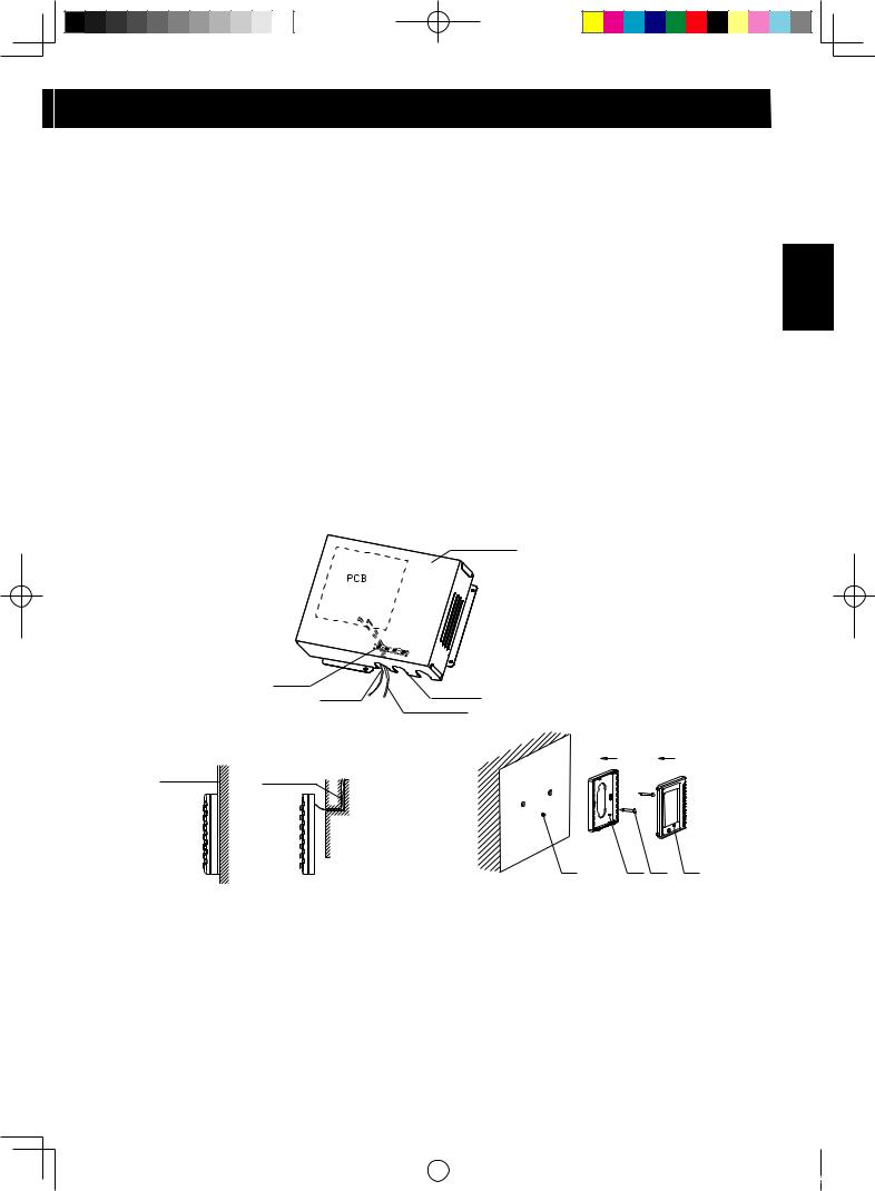
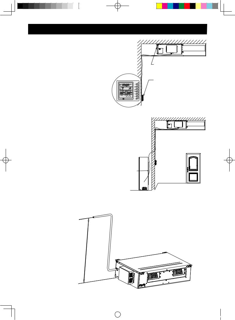
Position and method of installing wire controller
1 |
One end of the control wire of the wire controller is connected with main board of electric box of |
|
|
indoor unit inside, it should be tightened by wire clamp, the other end should be connected with the |
|
|
wire controller (Sketch map as shown in below). The control wire be used for the indoor unit and |
|
|
wire controller, which is the special control wire, the length is 8 meters, the material be adopted |
|
|
for the control wire should be metallic substance. The wire controller could not be disassembled |
|
|
and the control wire be used for the wire controller should not be changed by users optionally, the |
ENGLISH |
|
a recess or a embedded wire hole to bury the control wire. |
|
|
installation and maintenance should be carried out by the professional personnel. |
|
2 |
Select an installation position. According to the size of the control wire of the wire controller, leave |
|
3If the control wire between the wire controller and the indoor unit is surface-mounted, use 1# metallic pipe and make matching recess in the wall (Refer to Figure 1); If concealed installation is adopted, 1# metallic pipe can be used (Refer to Figure 2).
4No matter if surface mounting or concealed mounting is selected, it is required to drill 2 holes (in the same level) which distance shall be the same as the distance (60mm) of installation holes in the bottom plate of the wire controller. Then insert a wood plug into each hole. Fix the bottom plate of the wire controller to the wall by using the two holes. Plug the control wire onto the control panel. Lastly install the panel of the wire controller.
Caution:
During the installation of the bottom plate of the wire controller, pay attention to the direction of the bottom plate. The plate’s side with two notches must be at the lower position, and otherwise the panel of the wire controller cannot be correctly installed.
Electric box cover
Sketch map for indoor unit control wire
Wire clamp
Control wire |
Cable-cross loop |
|
Communication wire |
metallic pipe |
metallic pipe |
1 2 3 4
Figure 1: |
Figure 2: |
Schematic diagram of installation |
|
Surface mounting of |
Concealed mounting of |
|
|
cable |
cable |
No. |
Name |
|
|
1 |
Wall surface |
|
|
2 |
Bottom plate of wire controller |
|
|
3 |
Screw M4X10 |
|
|
4 |
Panel of wire controller |
Caution:
• The communication distance between the main board and the wire controller is 8 meters.
• The wire controller shall not be installed in a place where there is water drop or large amount of water vapor.
E-21
|
|
|
|
|
|
|
|
|
|
|
|
|
|
|
|
GREE_duct_eng_1022.indd 21 |
|
08.10.27 3:32:13 PM |
|
|
|
||
|
|
||||||
|
|
|
|
|
|
|
|
INSTRUCTIONS OF UNIT INSTALLATION
Electrical installation
Caution:
Before installing the electrical equipment, take care on the following matters.
• Check if the power supply is identical to the ratings on the nameplate.
• The capacity of the power supply must be large enough.
• The cable must be installed by professional personnel.
• Fit a disconnect switch, having a contact separation of at least 3mm in all poles, to the electricity power line.
• Use a cable which is not lighter than polychloroprene sheathed flexible cord (code designation
60245 IEC 57).
Connection of single wire
1 Use wire stripper to strip the insulation layer (25mm long) from the end of the single wire. 2 Remove the screw from the terminal board of the air-conditioning unit.
3 Use pliers to bend the end of the single wire so that a loop matching the screw size is formed. 4 Put the screw through the loop of the single wire and fix the loop at the terminal board.
Connection of multiple twisted wires
1 Use wire stripper to strip the insulation layer (10mm long) from the end of the multiple twisted wires.
2 Remove the screw from the terminal board of the air-conditioning unit.
3 Use crimping pliers to connect a terminal (matching the size of the screw) at the end of the multiple twisted wires.
4 Put the screw through the terminal of the multiple twisted wires and fix the terminal at the terminal board.
Warning:
If the power supply flexible line or the signal line of the equipment is damaged, only use special flexible line to replace it.
• Before connecting lines, read the voltages of the relevant parts on the nameplate. Then carry out line connection according to the schematic diagram.
• The air-conditioning unit shall have special power supply line which shall be equipped with electricity leakage switch and air switch, so as to deal with overload conditions.
• The air-conditioning unit must have grounding to avoid hazard owing to insulation failure.
• All fitting lines must use crimp terminals or single wire. If multiple twisted wires are connected to terminal board, arc may arise.
• All line connections must conform to the schematic diagram of lines. Wrong connection may cause abnormal operation or damage of the air-conditioning unit.
• Do not let any cable contact the refrigerant pipe, the compressor and moving parts such as fan.
• Do not change the internal line connections inside the air-conditioning unit. The manufacturer shall not be liable for any loss or abnormal operation arising from wrong line connections.
Power cable connection:
1 Remove the front-side panel of the outdoor unit. 2 Pass the cable through rubber ring.
3 Connect the power supply cable to the “L, N” terminals and the grounding screw on the metal electric box.
4 Fix the cable with cable fastener.
Recommend circuit breaker and power cable
Model |
Power supply |
Circuit breaker |
Min. cross sectional area |
|
|
|
of power cable |
GB-X18JR |
220-240V ~ 50Hz |
6A |
1.0 mm2 |
GU-X18JR |
|
10A |
2.5 mm2 |
GB-X24JR |
220-240V ~ 50Hz |
6A |
1.0 mm2 |
GU-X24JR |
|
10A |
2.5 mm2 |
GB-X36JR |
220-240V ~ 50Hz |
6A |
1.0 mm2 |
GU-X36JR |
|
25A |
6.0 mm2 |
•If the power cable is longer than 15 meters, please enlarge the cross section of power cable adequately, in order to avoid the accident due to overload.
E-22
|
|
|
|
|
|
|
|
|
|
|
|
|
|
|
|
GREE_duct_eng_1022.indd 22 |
|
08.10.27 3:32:13 PM |
|
|
|
||
|
|
||||||
|
|
|
|
|
|
|
|
 Loading...