


CODE : 00ZAL1551/A1E
DIGITAL COPIER
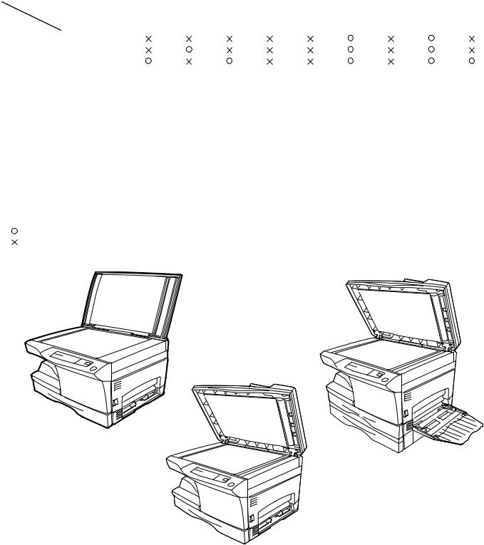
AL-1340 AL-1451
(AL-1551) MODEL AL-1551
|
|
CONTENTS |
|
|
|
[ 1 ] GENERAL . . . . . . . . . . . . . . . . . . . . . . . . . . . . . . . . . . . . . . . |
. 1 |
- 1 |
|||
[ 2 ] SPECIFICATIONS . . . . . . . . . . . . . . . . . . . . . . . . . . . . . . . . . . |
2 |
- 1 |
|||
[ 3 ] CONSUMABLE PARTS . . . . . . . . . . . . . . . . . . . . . . . . . . . . . . |
3 |
- 1 |
|||
[ 4 ] EXTERNAL VIEWS AND INTERNAL STRUCTURES . . . . . . . |
4 |
- 1 |
|||
[ 5 ] UNPACKING AND INSTALLATION. . . . . . . . . . . . . . . . . . . . . . |
5 |
- 1 |
|||
[ 6 |
] COPY PROCESS . . . . . . . . . . . . . . . . . . . . . . . . . . . . . . . . . . . |
6 |
- 1 |
||
[ 7 |
] OPERATIONAL DESCRIPTIONS. . . . . . . . . . . . . . . . . . . . . . . |
7 |
- 1 |
||
[ 8 |
] DISASSEMBLY AND ASSEMBLY . . . . . . . . . . . . . . . . . . . . . . |
8 |
- 1 |
||
[ 9 |
] ADJUSTMENTS . . . . . . . . . . . . . . . . . . . . . . . . . . . . . . . . . . . . |
9 |
- 1 |
||
[10] SIMULATION,TROUBLE CODES . . . . . . . . . . . . . . . . . . . . . |
10 |
- 1 |
|||
[11] USER PROGRAMS . . . . . . . . . . . . . . . . . . . . . . . . . . . . . . . . |
11 |
- 1 |
|||
[12] ELECTRICAL SECTION . . . . . . . . . . . . . . . . . . . . . . . . . . . . |
12 |
- 1 |
|||
[13] CIRCUIT DIAGRAM . . . . . . . . . . . . . . . . . . . . . . . . . . . . . . . . |
13 |
- 1 |
|||
Parts marked with “ “ are important for maintaining the safety of the machine.
Be sure to replace these parts with specified ones for maintaining the safety and performance of the machine.
This document has been published to be used for SHARP CORPORATION after sales service only.
The contents are subject to change without notice.

CAUTION
This product is a class 1 laser product that complies with 21CFR 1040.10 and 1040.11 of the CDRH standard and IEC825. This means that this machine does not produce hazardous laser radiation. The use of controls, adjustments or performance of procedures other than those specified herein may result in hazardous radiation exposure.
This laser radiation is not a danger to the skin, but when an exact focusing of the laser beam is achieved on the eye’s retina, there is the danger of spot damage to the retina.
The following cautions must be observed to avoid exposure of the laser beam to your eyes at the time of servicing.
1)When a problem in the laser optical unit has occurred, the whole optical unit must be exchanged as a unit, not as individual parts.
2)Do not look into the machine with the main switch turned on after removing the developer unit, toner cartridge, and drum cartridge.
3)Do not look into the laser beam exposure slit of the laser optical unit with the connector connected when removing and installing the optical system.
4)The middle frame contains the safety interlock switch.
Do not defeat the safety interlock by inserting wedges or other items into the switch slot.
LASER WAVE – LENGTH : 780 ~ 795 Pulse times : 0.481ms/6mm
Out put power : 0.20 ± 0.03mW
CAUTION |
VARO ! |
|
INVISIBLE LASER RADIATION, |
AVATTAESSA JA SUOJALUKITUS |
|
WHEN OPEN AND INTERLOCKS DEFEATED. |
OHITETTAESSA OLET ALTTIINA |
|
NÄKYMÄTTÖMÄLLE LASERSÄTEILYLLE ÄLÄ |
||
AVOID EXPOSURE TO BEAM. |
||
KATSO SÄTEESEEN. |
||
|
VORSICHT
UNSICHTBARE LASERSTRAHLUNG, WENN ABDECKUNG GEÖFFNET UND
SICHERHEITSVERRIEGELUNG ÜBERBRÜCKT. NICHT DEM STRAHL AUSSETZEN.
ADVARSEL
USYNLIG LASERSTRÅLNING VED ÅBNING, NÅR SIKKERHEDSBRYDERE ER UDE AF
FUNKTION. UNDGÅ UDSAETTELSE FOR STRÅLNING.
VARNING !
OSYNLIG LASERSTRÅLNING NÄR DENNA DEL ÄR ÖPPNAD OCH SPÄRREN ÄR URKOPPLAD. BETRAKTA EJ STRÅLEN. – STRÅLEN ÄR FARLIG.

At the production line, the output power of the scanner unit is adjusted to 0.57 MILLI-WATT PLUS 20 PCTS and is maintained constant by the operation of the Automatic Power Control (APC). Even if the APC circuit fails in operation for some reason, the maximum output power will only be 15 MILLI-WATT 0.1 MICRO-SEC. Giving and accessible emission level of 42 MICRO-WATT which is still-less than the limit of CLASS-1 laser product.
Caution
This product contains a low power laser device. To ensure continued safety do not remove any cover or attempt to gain access to the inside of the product. Refer all servicing to qualified personnel.
VAROITUS! LAITTEEN KÄYTTÄMINEN MUULLA
KUIN TÄSSÄ KÄYTTÖOHJEESSA MAINITULLA
TAVALLA SAATTAA ALTISTAA KÄYTTÄJÄN
TURVALLISUUSLUOKAN 1 YLITTÄVÄLLE
NÄKYMÄTTÖMÄLLE LASERSÄTEILYLLE.
VARNING - OM APPARATEN ANVÄNDS PÅ ANNAT SÄTT ÄN I DENNA BRUKSANVISNING SPECIFICERATS, KAN ANVÄNDAREN UTSÄTTAS FÖR OSYNLIG LASERSTRÅLNING, SOM ÖVERSKRIDER GRÄNSEN FÖR LASERKLASS 1.
|
|
|
|
|
|
|
|
|
|
LUOKAN 1 LASERLAITE |
|
The foregoing is applicable only to the 220V |
|||||
|
|
|
KLASS 1 LASER APPARAT |
||
model, 230V model and 240V model. |
|
|
|
|
|
|
|
|
|
CONTENTS
[1]GENERAL
1. Major functions. . . . . . . . . . . . . . . . . . . . . . . . . . . . . . . . . . . 1-1
[2]SPECIFICATIONS
1. Basic Specifications . . . . . . . . . . . . . . . . . . . . . . . . . . . . . . . 2-1 2. Operation specifications. . . . . . . . . . . . . . . . . . . . . . . . . . . . 2-1 3. Copy performance . . . . . . . . . . . . . . . . . . . . . . . . . . . . . . . . 2-3 4. Printer specifications . . . . . . . . . . . . . . . . . . . . . . . . . . . . . . 2-4 5. SPF . . . . . . . . . . . . . . . . . . . . . . . . . . . . . . . . . . . . . . . . . . . 2-4 6. RSPF . . . . . . . . . . . . . . . . . . . . . . . . . . . . . . . . . . . . . . . . . . 2-4
[3]CONSUMABLE PARTS
1. Supply system table. . . . . . . . . . . . . . . . . . . . . . . . . . . . . . . 3-1 2. Environmental . . . . . . . . . . . . . . . . . . . . . . . . . . . . . . . . . . . 3-1 3. Production control number(lot No.) identification . . . . . . . . . 3-2
[4]EXTERNAL VIEWS AND INTERNAL STRUCTURES
1. Appearance . . . . . . . . . . . . . . . . . . . . . . . . . . . . . . . . . . . . . 4-1 2. Internal. . . . . . . . . . . . . . . . . . . . . . . . . . . . . . . . . . . . . . . . . 4-1 3. Operation panel . . . . . . . . . . . . . . . . . . . . . . . . . . . . . . . . . . 4-2 4. Motors and solenoids. . . . . . . . . . . . . . . . . . . . . . . . . . . . . . 4-3 5. Sensors and switches . . . . . . . . . . . . . . . . . . . . . . . . . . . . . 4-4 6. PWB unit . . . . . . . . . . . . . . . . . . . . . . . . . . . . . . . . . . . . . . . 4-5 7. Cross sectional view . . . . . . . . . . . . . . . . . . . . . . . . . . . . . . 4-6
[5]UNPACKING AND INSTALLATION
1. Copier installation . . . . . . . . . . . . . . . . . . . . . . . . . . . . . . . . 5-1 2. Cautions on handling . . . . . . . . . . . . . . . . . . . . . . . . . . . . . . 5-1 3. Checking packed components and accessories . . . . . . . . . 5-2 4. Unpacking . . . . . . . . . . . . . . . . . . . . . . . . . . . . . . . . . . . . . . 5-2 5. Removing protective packing materials . . . . . . . . . . . . . . . . 5-2 6. Installing the TD cartridge . . . . . . . . . . . . . . . . . . . . . . . . . . 5-2 7. Loading copy paper . . . . . . . . . . . . . . . . . . . . . . . . . . . . . . . 5-3 8. Power to copier . . . . . . . . . . . . . . . . . . . . . . . . . . . . . . . . . . 5-4 9. Installing the printer driver . . . . . . . . . . . . . . . . . . . . . . . . . . 5-4 10. Parallel interface. . . . . . . . . . . . . . . . . . . . . . . . . . . . . . . . . . 5-6
[6]COPY PROCESS
1. Functional diagram . . . . . . . . . . . . . . . . . . . . . . . . . . . . . . . 6-1 2. Outline of print process . . . . . . . . . . . . . . . . . . . . . . . . . . . . 6-2 3. Actual print process . . . . . . . . . . . . . . . . . . . . . . . . . . . . . . . 6-2
[7]OPERATIONAL DESCRIPTIONS
1. Outline of operation . . . . . . . . . . . . . . . . . . . . . . . . . . . . . . . 7-1 2. Scanner section . . . . . . . . . . . . . . . . . . . . . . . . . . . . . . . . . . 7-2 3. Laser unit . . . . . . . . . . . . . . . . . . . . . . . . . . . . . . . . . . . . . . . 7-3 4. Fuser section . . . . . . . . . . . . . . . . . . . . . . . . . . . . . . . . . . . . 7-3 5. Paper feed section and paper transport section . . . . . . . . . 7-5 6. Process unit new drum detection mechanism . . . . . . . . . . . 7-8 7. SPF section . . . . . . . . . . . . . . . . . . . . . . . . . . . . . . . . . . . . . 7-8 8. D-D (Duplex to Duplex) mode paper/
document transport (Duplex model). . . . . . . . . . . . . . . . . . . 7-9
[8]DISASSEMBLY AND ASSEMBLY
1. High voltage section . . . . . . . . . . . . . . . . . . . . . . . . . . . . . . .8-1 2. Operation panel section . . . . . . . . . . . . . . . . . . . . . . . . . . . .8-2 3. Optical section . . . . . . . . . . . . . . . . . . . . . . . . . . . . . . . . . . .8-3 4. Fusing section. . . . . . . . . . . . . . . . . . . . . . . . . . . . . . . . . . . .8-4 5. Tray paper feed/transport section . . . . . . . . . . . . . . . . . . . . .8-7 6. Manual paper feed section . . . . . . . . . . . . . . . . . . . . . . . . .8-11 7. Rear frame section . . . . . . . . . . . . . . . . . . . . . . . . . . . . . . .8-15 8. Power section . . . . . . . . . . . . . . . . . . . . . . . . . . . . . . . . . . .8-16 9. SPF section (SPF model only) . . . . . . . . . . . . . . . . . . . . . .8-16 10. 2nd cassette section . . . . . . . . . . . . . . . . . . . . . . . . . . . . . .8-19 11. Duplex motor section (RSPF model only). . . . . . . . . . . . . .8-21 12. Reverse roller section (RSPF model only) . . . . . . . . . . . . .8-21 13. RSPF section (RSPF model only) . . . . . . . . . . . . . . . . . . .8-21
[9] ADJUSTMENTS
1. Optical section . . . . . . . . . . . . . . . . . . . . . . . . . . . . . . . . . . .9-1 2. Copy density adjustment . . . . . . . . . . . . . . . . . . . . . . . . . . .9-8 3. High voltage adjustment . . . . . . . . . . . . . . . . . . . . . . . . . . . .9-9 4. Duplex adjustment . . . . . . . . . . . . . . . . . . . . . . . . . . . . . . . .9-9
[10] SIMULATION, TROUBLE CODES
1. Entering the simulation mode . . . . . . . . . . . . . . . . . . . . . . .10-1 2. List of simulations . . . . . . . . . . . . . . . . . . . . . . . . . . . . . . . .10-2 3. Contents of simulations (new or revised simulations only) .10-3 4. Trouble codes . . . . . . . . . . . . . . . . . . . . . . . . . . . . . . . . . .10-14
[11] USER PROGRAM
1. Functions which can be set with the user program. . . . . . .11-1
2.Change the setting.. . . . . . . . . . . . . . . . . . . . . . . . . . . . . . .11-1
[12]ELECTRICAL SECTION
1. Block diagram . . . . . . . . . . . . . . . . . . . . . . . . . . . . . . . . . . .12-1 2. Circuit descriptions . . . . . . . . . . . . . . . . . . . . . . . . . . . . . . .12-3 3. Reset circuit . . . . . . . . . . . . . . . . . . . . . . . . . . . . . . . . . . .12-10 4. Heater lamp control circuit . . . . . . . . . . . . . . . . . . . . . . . .12-11 5. Driver circuit (Solenoid) . . . . . . . . . . . . . . . . . . . . . . . . . .12-12 6. Toner supply motor drive circuit . . . . . . . . . . . . . . . . . . . .12-12 7. Main motor drive circuit. . . . . . . . . . . . . . . . . . . . . . . . . . .12-12 8. Mirror motor circuit . . . . . . . . . . . . . . . . . . . . . . . . . . . . . .12-13 9. Duplex motor circuit . . . . . . . . . . . . . . . . . . . . . . . . . . . . .12-13 10. Power circuit block diagram . . . . . . . . . . . . . . . . . . . . . . .12-14 11. CL invertor PWB (circuit) . . . . . . . . . . . . . . . . . . . . . . . . .12-17 12. CCD PWB operational description . . . . . . . . . . . . . . . . . .12-17 13. Operation section . . . . . . . . . . . . . . . . . . . . . . . . . . . . . . .12-18
[13] CIRCUIT DIAGRAM . . . . . . . . . . . . . . . . . . . . . . . . . . . . .13-1
[1] GENERAL
1. Major functions
Configurations
|
Item |
CPM |
SB/MB |
2 Tray |
|
SPF |
R-SPF |
FAX |
GDI with |
GDI |
PCL with |
SOPM |
Duplex |
|
|
|
|
|
|
|
|
|
USB |
without |
USB |
|
|
Model |
|
|
|
|
|
|
|
|
|
USB |
|
|
|
|
|
|
|
|
|
|
|
|
|
|
|
|
|
AL-1340 |
13CPM |
SB |
|
|
|
|
|
|
|
|
|
|
|
|
|
|
|
|
|
|
|
|
|
|
|
|
|
AL-1451 |
14CPM |
SB |
|
|
|
|
|
|
|
|
|
|
|
|
|
|
|
|
|
|
|
|
|
|
|
|
|
AL-1551 |
15CPM |
MB |
|
|
|
|
|
|
|
|
|
|
|
|
|
|
|
|
|
|
|
|
|
|
|
|
|
Descriptions of items |
|
|
|
|
|
|
|
|
|
|
|
||
CPM: |
Copy speed (Copies Per Minute) |
|
|
|
|
|
|
|
|
||||
SB/MB: |
SB = Manual feed single bypass, MB = Manual feed multi bypass |
|
|
|
|
|
|||||||
2 tray: |
Second cassette unit. |
|
|
|
|
|
|
|
|
||||
SPF: |
|
Original feed unit |
|
|
|
|
|
|
|
|
|
|
|
R-SPF: |
Duplex original feed unit |
|
|
|
|
|
|
|
|
||||
FAX: |
|
FAX function. |
|
|
|
|
|
|
|
|
|
|
|
GDI with USB: |
GDI printer function with USB. |
|
|
|
|
|
|
|
|
||||
GDI without USB: GDI printer function without USB. |
|
|
|
|
|
|
|
|
|||||
PCL with USB: |
PCL printer function with USB. |
|
|
|
|
|
|
|
|
||||
SOPM: |
Scan Once Print Many function (Many copies are made by one scan.) |
|
|
|
|
||||||||
Duplex: |
Auto duplex copy function |
|
|
|
|
|
|
|
|
||||
Descriptions of table |
|
|
|
|
|
|
|
|
|
|
|
||
: |
Standard provision |
|
|
|
|
|
|
|
|
|
|
|
|
: |
No function or no option available |
|
|
|
|
|
|
|
|
|
|
||
Opt: |
Option |
|
|
|
|
|
|
|
|
|
|
|
|
AL-1451
AL-1340
AL-1551
AL-1551 GENERAL 1-1
[2] SPECIFICATIONS
1. Basic Specifications
Item |
|
|
|
|
|
|
|
Type |
|
Desktop |
|
|
|
|
|
Copy system |
|
Dry, electrostatic |
|
|
|
|
|
Segment (class) |
|
Digital personal copier |
|
|
|
|
|
Copier dimensions |
AL-1340 |
20.4"(W)X17.5"(D)X11.5"(H) (518mm(W)X445mm(D)X293mm(H)) |
|
|
|
|
|
|
AL-1451 |
20.4"(W)X18.8"(D)X15.0"(H) (518mm(W)X477mm(D)X379mm(H)) |
|
|
|
|
|
|
AL-1551 |
20.4"(W)X18.8"(D)X18.3"(H) (518mm(W)X477mm(D)X464mm(H)) |
|
|
|
|
|
Weight |
AL-1340 |
39.7lbs.(18Kg) |
TD and drum cartridges included |
(Approximately) |
|
|
|
AL-1451 |
47.4lbs.(21.5Kg) |
|
|
|
|
|
|
|
AL-1551 |
54.3lbs.(24.6Kg) |
|
|
|
|
|
2. Operation specifications
|
Section, item |
Details |
|
|
|
|
|
|
|
Paper feed |
Paper feed |
|
AL-1340 / 1451 |
1 tray (250 sheet) + single bypass |
section |
system |
|
|
|
|
AL-1551 |
2 tray (500 sheet) + multi bypass (50 sheet) |
||
|
|
|
|
|
|
AB system |
Tray paper feed |
Paper size |
A4, B5, A5 (Landscape) |
|
|
section |
|
|
|
|
Paper weight |
56 - 80g/m (15 - 21 lbs.) |
|
|
|
|
|
|
|
|
|
Paper feed capacity |
250 sheets |
|
|
|
|
|
|
|
|
Kinds |
Standard paper, specified paper, recycled paper |
|
|
|
|
|
|
|
|
Remark |
User adjustment of paper guide available |
|
|
|
|
|
|
|
Multi bypass paper |
Paper size |
A4, B5, A5, B6, A6 (Landscape) |
|
|
feed section |
|
|
|
|
Paper weight |
52 - 130g/m (14 - 34.5 lbs.) |
|
|
|
|
|
|
|
|
|
Paper feed capacity |
50 sheets |
|
|
|
|
|
|
|
|
Kinds |
Standard paper, specified paper, recycled paper, OHP, |
|
|
|
|
Label, Postal card |
|
|
|
|
|
|
|
|
Remark |
User adjustment of paper guide available |
|
|
|
|
|
|
|
Single bypass paper |
Paper size |
A4, B5, A5, B6, A6 (Landscape) |
|
|
feed section |
|
|
|
|
Paper weight |
52 - 130g/m (14 - 34.5 lbs.) |
|
|
|
|
|
|
|
|
|
Paper feed capacity |
1 sheet |
|
|
|
|
|
|
|
|
Kinds |
Standard paper, specified paper, recycled paper, OHP, |
|
|
|
|
Label, Postal card |
|
|
|
|
|
|
|
|
Remark |
User adjustment of paper guide available |
|
|
|
|
|
|
Inch system |
Tray paper feed |
Paper size |
8-1/2" x 14", 8-1/2 x 11", 8-1/2" x 5-1/2" (Landscape) |
|
|
section |
|
|
|
|
Paper weight |
15 - 21 lbs. |
|
|
|
|
|
|
|
|
|
Paper feed capacity |
250 sheets |
|
|
|
|
|
|
|
|
Kinds |
Standard paper, specified paper, recycled paper |
|
|
|
|
|
|
|
|
Remark |
User adjustment of paper guide available |
|
|
|
|
|
|
|
Multi bypass paper |
Paper size |
8-1/2" x 14", 8-1/2 x 11", 8-1/2" x 5-1/2", 3-1/2" x 5-1/2" |
|
|
feed section |
|
(Landscape) |
|
|
|
|
|
|
|
|
Paper weight |
14 - 34.5 lbs. |
|
|
|
|
|
|
|
|
Paper feed capacity |
50 sheets |
|
|
|
|
|
|
|
|
Kinds |
Standard paper, specified paper, recycled paper, OHP, |
|
|
|
|
Label, Postal card |
|
|
|
|
|
|
|
|
Remark |
User adjustment of paper guide available |
|
|
|
|
|
|
|
Single bypass paper |
Paper size |
8-1/2" x 14", 8-1/2 x 11", 8-1/2" x 5-1/2" (Landscape) |
|
|
feed section |
|
|
|
|
Paper weight |
14 - 34.5 lbs. |
|
|
|
|
|
|
|
|
|
Paper feed capacity |
1 sheet |
|
|
|
|
|
|
|
|
Kinds |
Standard paper, specified paper, recycled paper, OHP, |
|
|
|
|
Label, Postal card |
|
|
|
|
|
|
|
|
Remark |
User adjustment of paper guide available |
|
|
|
|
|
Paper exit section |
Exit way |
|
Face down |
|
|
|
|
|
|
|
|
Capacity of output tray |
|
100 sheets |
|
|
|
|
|
Originals |
|
Original set |
|
Center Registration (left edge) |
|
|
|
|
|
|
|
Max. original size |
|
B4 (10" x 14") |
|
|
|
|
|
|
|
Original kinds |
|
sheet, book |
|
|
|
|
|
|
|
Original size detection |
|
None |
|
|
|
|
|
AL-1551 SPECIFICATIONS 2-1
|
Section, item |
Details |
|
|
|
|
|
|
|
|
|
Optical section |
Scanning |
Scanning system |
|
|
CCD sensor scanning by lighting lamp scanner |
|
section |
|
|
|
|
|
CCD sensor |
Resolution |
|
400 dpi |
|
|
|
|
|
|
|
|
|
Lighting lamp |
Type |
|
Xenon lamp |
|
|
|
|
|
|
|
|
|
Voltage |
|
1.5kV |
|
|
|
|
|
|
|
|
|
Power consumption |
|
11 ± 3W |
|
|
|
|
|
|
|
|
Gradation |
|
|
256 gradations/8bit |
|
|
|
|
|
|
|
Writing |
Writing system |
|
|
Writing to OPC drum by the semiconductor laser |
|
section |
|
|
|
|
|
Laser unit |
Resolution |
|
600 dpi |
|
|
|
|
|
|
|
Image forming |
|
Photoconductor |
type |
|
OPC (30ø) |
|
|
|
|
|
|
|
|
|
Life |
|
18k |
|
|
|
|
|
|
|
|
Charger |
Charging system |
|
Saw -tooth charging with a grid, / (-) scorotron discharge |
|
|
|
|
|
|
|
|
|
Transfer system |
|
(+) DC corotron system |
|
|
|
|
|
|
|
|
|
Separation system |
|
(-) DC corotron system |
|
|
|
|
|
|
|
|
Developing |
Developing system |
|
Dry, 2-component magnetic brush development system |
|
|
|
|
|
|
|
|
Cleaning |
Cleaning system |
|
Counter blade system (Counter to rotation) |
|
|
|
|
|
|
Fusing section |
Fusing system |
|
|
Heat roller system |
|
|
|
|
|
|
|
|
|
Upper heat roller |
type |
|
Teflon roller |
|
|
|
|
|
|
|
|
Lower heat roller |
type |
|
Silicon rubber roller |
|
|
|
|
|
|
|
|
Heater lamp |
type |
|
Halogen lamp |
|
|
|
|
|
|
|
|
|
Voltage |
|
100V |
|
|
|
|
|
|
|
|
|
Power consumption |
|
800W |
|
|
|
|
|
|
Electrical section |
Power source |
Voltage |
|
100V, 110V, 120/127V, 230V, 240V |
|
|
|
|
|
|
|
|
|
|
Frequency |
|
Common use for 50 and 60Hz |
|
|
|
|
|
|
|
|
Power consumption |
Max. |
|
1000W |
|
|
|
|
|
|
|
|
|
Average |
AL-1340 |
260Wh/H *1) |
|
|
|
(during copying) |
|
|
|
|
|
AL-1451 |
280Wh/H *1) |
|
|
|
|
|
|
|
|
|
|
|
AL-1551 |
310Wh/H *1) |
|
|
|
|
|
|
|
|
|
Average (stand-by) |
|
70Wh/H *1) |
|
|
|
|
|
|
|
|
|
Pre-heat mode |
|
40Wh/H *1) |
|
|
|
|
|
|
|
|
|
Auto power shut-off mode |
20Wh/H *1) |
|
|
|
|
|
|
|
*1) May fluctuate due to environmental conditions and the input voltage.
AL-1551 SPECIFICATIONS 2-2
3. Copy performance
|
Section, item |
|
Details |
AL-1340 |
AL-1451 |
AL-1551 |
|
|
|
|
|
|
|
Copy magnification |
Fixed |
|
3 Reduction + 2 Enlargement |
|
||
|
|
magnification |
|
(AB system : 50, 70, 81, 100, 141, 200%) |
|
|
|
|
ratios |
|
(Inch system : 50, 64, 78, 129, 100, 200%) |
|
|
|
|
|
|
|
|
|
|
|
Zooming |
|
50 - 200% |
|
|
|
|
magnification |
|
(151 steps in 1% increments) |
|
|
|
|
ratios |
|
|
|
|
|
|
|
|
|
|
|
Manual steps |
|
|
5 steps |
|
|
|
(manual, photo) |
|
|
|
|
|
|
|
|
|
|
|||
Copy speed |
First copy time |
Tray paper feed |
9.6 sec. (Pre-heat mode:16 sec. or below / Auto power-shut-off mode : |
|||
|
|
|
|
23 sec. or below) |
|
|
|
|
|
|
|
|
|
|
|
|
Manual paper feed |
Single : 10.0 sec. / Multi : 8.0sec |
|
|
|
|
|
|
(Pre-heat mode:16 sec. or below / Auto power-shut-off mode : 23 sec. |
||
|
|
|
|
or below) |
|
|
|
|
|
|
|
|
|
|
AB system |
Copy speed |
Same size |
13 |
14 |
15 |
|
A4 |
(CPM) |
|
|
|
|
|
Enlargement |
13 |
14 |
15 |
||
|
(Landscape) |
|
|
|
|
|
|
|
Reduction |
13 |
14 |
15 |
|
|
|
|
||||
|
|
|
|
|
|
|
|
AB system |
Copy speed |
Same size |
13 |
14 |
15 |
|
B5 |
(CPM) |
|
|
|
|
|
Enlargement |
13 |
14 |
15 |
||
|
(Landscape) |
|
|
|
|
|
|
|
Reduction |
13 |
14 |
15 |
|
|
|
|
||||
|
|
|
|
|
|
|
|
Inch system |
Copy speed |
Same size |
13 |
14 |
15 |
|
8-1/2" x 14" |
(CPM) |
|
|
|
|
|
Enlargement |
13 |
14 |
15 |
||
|
(Landscape) |
|
|
|
|
|
|
|
Reduction |
13 |
14 |
15 |
|
|
|
|
||||
|
|
|
|
|
|
|
|
Inch system |
Copy speed |
Same size |
13 |
14 |
15 |
|
8-1/2" x 11" |
(CPM) |
|
|
|
|
|
Enlargement |
13 |
14 |
15 |
||
|
(Landscape) |
|
|
|
|
|
|
|
Reduction |
13 |
14 |
15 |
|
|
|
|
||||
|
|
|
|
|
|
|
Max. continuous copy quantity |
|
|
99 |
|
|
|
|
|
|
|
|
|
|
Void |
Void area |
leading edge |
1 - 4mm |
|
|
|
|
|
|
|
|
|
|
|
|
|
Trailing edge |
4mm or less |
|
|
|
|
|
|
|
|
|
|
|
|
Side edge void area |
3mm or less/per side |
|
|
|
|
|
|
|
||
|
|
Image loss |
leading edge |
same size: 3.0mm or less / Enlarge (200%): 1.5mm or less / Reduction |
||
|
|
|
|
(50%): 6.0mm or less |
|
|
|
|
|
|
|
||
|
|
|
Trailing edge |
same size: 3.0mm or less / Enlarge (200%): 1.5mm or less / Reduction |
||
|
|
|
|
(50%): 6.0mm or less |
|
|
|
|
|
|
|
||
|
|
|
Side edge void area |
same size: 3.0mm or less / Enlarge (200%): 1.5mm or less / Reduction |
||
|
|
|
|
(50%): 6.0mm or less |
|
|
|
|
|
|
|
|
|
Warm-up time |
|
|
0 sec. |
|
|
|
|
|
|
|
|
|
|
Power save mode reset time |
|
|
0 sec. |
|
|
|
|
|
|
|
|
|
|
Paper jam recovery time |
|
|
0 sec. |
|
|
|
|
|
|
|
|
|
|
AL-1551 SPECIFICATIONS 2-3
4. Printer specifications
Resolution |
600 or 300 can be selected. |
Page description language |
SHARP GDI |
Page onentation |
Portrait or Landscape |
First print time |
Approx. 9.6 seconds* |
Print speed(multiple pages) |
Max.12 pages per minute(letter or A4) |
Interface port |
Bi-directional parallel interface(IEEE 1284 compliant) |
*First print time may differ depending on operating conditions, such as power-supply voltage and room temperature. Also the time may differ depending on data quantity to be printed and applications.
5. SPF
Original capacity |
30 sheets (52 to 90g/m )(14 to 23.9 lbs.) |
Original size |
B4 to A5/10" x 14" to 5-1/2" x 8-1/2" |
Original replacement speed |
12CPM(A4/8-1/2" x 11"Landscape)(14CPM model) |
Original placement |
Face up |
Original weight |
52 to 90g/m (14 - 23.9lbs.) |
Mixed feeding(Paper size) |
Performance Degraded |
Original which cannot |
Thermal papers, originals with punch holes for files, be used folded paper, transparent originals such as OHP films, |
|
stapled or clip used originals with cover up liquid used, Originals with tape sealed, originals with high level frictional |
|
coefficient such as photos or catalogs. |
6. RSPF
Original capacity |
|
30 sheets (52 to 90g/m )(14 to 23.9 lbs.) |
|
Original size |
|
B4 to A5/10" x 14" to 5-1/2" x 8-1/2" |
|
Original replacement speed |
|
12CPM(A4/8-1/2" x 11"Landscape)(15CPM model) |
|
Job speed(Tray1,Landscape) |
Single copy |
S to S |
12CPM |
|
|
S to D |
5.6CPM |
|
|
D to S |
5.5CPM |
|
|
D to D |
5.2CPM |
|
Multi copy |
S to S |
15CPM |
|
|
D to S |
15CPM |
Original placement |
|
Face up |
|
Original weight |
|
52 to 90g/m (14 - 23.9lbs.) |
|
Mixed feeding(Paper size) |
|
Performance Degraded |
|
Original which cannot |
|
Thermal papers, originals with punch holes for files, be used folded paper, transparent |
|
|
|
originals such as OHP films, stapled or clip used originals with cover up liquid used, |
|
|
|
Originals with tape sealed, originals with high level frictional coefficient such as photos or |
|
|
|
catalogs. |
|
AL-1551 SPECIFICATIONS 2-4

[3] CONSUMABLE PARTS
1. Supply system table
Common to all destinations
No. |
Name |
Content |
Life |
Product name |
Package |
|
|
|
|
|
|
1 |
Develop cartridge (Black) x 1 |
Toner/developer cartridge x 1 |
6K |
AL-100TD |
5 |
|
(Except Europe) |
(Toner: Net weight 220g)(Developer: Net weight 190g) |
(5% document) |
|
|
|
|
|
|
|
|
2 |
Develop cartridge (Black) x 1 |
Toner/developer cartridge x 1 |
4K |
AL-110TD |
5 |
|
(Except Europe) |
(Toner: Net weight 124g)(Developer: Net weight 190g) |
(5% document) |
|
|
|
|
|
|
|
|
3 |
Develop cartridge (Black) x 1 |
Toner/developer cartridge x 1 |
4K |
AL-110DC |
5 |
|
(Europe) |
(Toner: Net weight 124g)(Developer: Net weight 190g) |
(5% document) |
|
|
|
|
|
|
|
|
4 |
Drum cartirdge |
Drum cartridge |
18K |
AL-100DR |
5 |
|
|
|
|
|
|
2. Environmental
The environmental conditions for assuring the copy quality and the machine operations are as follows:
(1) Normal operating condition |
(4) Supply storage condition |
Temperature:20 - 25°C
Humidity:65 ± 5%RH
Humidity (RH)
(2) Acceptable operating condition
Humidity (RH) |
|
|
85% |
|
|
60% |
|
|
20% |
|
|
10˚C |
30˚C |
35˚C |
90%
20%
–5˚C |
45˚C |
(3) Optical condition
Humidity (RH) |
|
|
90% |
|
|
60% |
|
|
15% |
|
|
–25˚C |
30˚C |
40˚C |
AL-1551 CONSUMABLE PARTS 3-1
3.Production control number(lot No.) identification
<Developing cartridge>
 Production month Production day Destination code
(Dealer, distributor, OEM, etc.) Production place
(SOCC: Fixed to B.) End digit of year Version No.
* Destination
Division |
|
No. |
|
|
|
|
|
EX Destination |
|
A same pack |
G |
|
|
|
|
|
|
B same pack |
H |
|
|
|
|
Option Destination |
|
A |
P |
|
|
|
|
|
|
B |
Q |
|
|
|
|
<Drum cartridge>
The label on the drum cartridge shows the date of production. (SOCC production)
 Production month Production day Destination code
(Dealer, distributor, OEM, etc.) Production place
(SOCC: Fixed to B.) End digit of year Version No.
<JAPAN production>
Ver.A 9 |
1 |
1 0001 X |
Production month
(1 - 9 = Jan. - Sep. 0 = Oct. X = Nov. Y = Dec.) Serial number of month
Fixed to 1. Pack division
(See table below) End digit of year Version No.
Division |
No. |
|
|
Ex production |
1 |
|
|
Option |
2 |
|
|
Same pack |
3 |
|
|
Production control
label attachment position
Production control
label attachment position(*1)
*1 The production control label is not attached to the cartridge of a China product.
AL-1551 CONSUMABLE PARTS 3-2

[4] EXTERNAL VIEWS AND INTERNAL STRUCTURES
1. Appearance
9
8 |
7
6
|
|
Original cover |
10 |
SPF |
|
|
18 |
|
11 |
17 |
|
1 |
|
19 |
12 |
|
|
2 |
RSPF |
20 |
|
|
21 |
18 |
|
3 |
|
|
|
4 |
16 |
19 |
|
|
||
|
|
|
|
5 |
|
15 |
20 |
|
|
14 |
|
1 |
Original cover |
2 |
Side cover |
3 |
Bypass tray |
4 |
Bypass tray guides |
5 |
Side cover open button |
6 |
Front cover |
7 |
Paper tray |
8 |
Operation panel |
9 |
Original table |
10 |
Handle |
11 |
GDI printer interface |
12 |
Paper output tray |
13 |
Paper output tray extension |
14 |
Handle |
15 |
Power switch |
16 |
Power cord socket |
17 |
SPF exit area *1 |
18 |
Original guides |
19 |
Document feeder tray |
20 |
Feeding roller cover |
21 |
RSPF exit area *2 |
*1 SPF only *2 RSPF only |
|
|
|
|
|
2. Internal |
|
|
|
|
|
|
1 |
|
|
3 |
|
|
|
2 |
|
4 |
|
|
|
|
|
|
|
|
7 |
|
|
|
|
5 |
6 |
|
|
|
|
|
|
|
|
|
|
|
|
|
1 |
TD cartridge lock release button |
2 |
|
TD cartridge |
|
3 |
|
Drum cartridge |
4 |
Drum cartridge handle |
5 |
|
Fusing unit release lever |
|
6 |
|
Charger cleaner |
7 |
Transfer charger |
|
|
|
|
|
|
|
AL-1551 EXTERNAL VIEWS AND INTERNAL STRUCTURES 4-1

3. Operation panel
|
1 |
2 |
3 |
4 |
|
5 |
|
6 |
7 |
|
8 |
9 |
10 |
11 |
12 |
|||||||||||||||
|
|
|
|
|
|
|
|
|
|
|
|
|
|
|
|
|
|
|
|
|
|
|
|
|
|
|
|
|
|
|
|
|
|
|
|
|
|
|
|
|
|
|
|
|
|
|
|
|
|
|
|
|
|
|
|
|
|
|
|
|
|
|
|
|
|
|
|
|
|
|
|
|
|
|
|
|
|
|
|
|
|
|
|
|
|
|
|
|
|
|
|
|
|
|
|
|
|
|
|
|
|
|
|
|
|
|
|
|
|
|
|
|
|
|
|
|
|
|
|
|
|
|
|
|
|
|
|
|
|
|
|
|
|
|
|
|
|
|
|
|
|
|
|
|
|
|
|
|
|
|
|
|
|
|
|
|
|
|
|
|
|
|
|
|
|
|
|
|
|
|
|
|
|
|
|
|
|
|
|
|
|
|
|
|
|
|
|
|
|
|
|
|
|
|
|
|
|
|
|
|
|
|
|
|
|
|
|
|
|
|
|
|
|
|
|
|
|
|
|
|
|
|
|
|
|
|
|
|
|
|
|
|
|
|
|
|
|
|
|
|
|
|
|
|
|
|
|
|
|
|
|
|
|
|
|
|
|
|
|
|
|
|
|
|
|
|
|
|
|
|
|
|
|
|
|
|
|
|
|
|
|
|
|
|
|
|
|
|
|
|
|
|
|
|
|
|
|
|
|
|
|
|
|
|
|
|
|
|
|
|
|
|
|
|
|
|
|
|
|
|
|
|
|
|
|
|
|
|
|
|
|
|
|
|
|
|
|
|
|
|
|
|
|
|
|
|
|
|
|
|
|
|
|
|
|
|
|
|
|
|
|
|
|
|
|
|
|
|
|
|
|
|
|
|
|
|
|
|
|
|
|
|
|
|
|
|
|
|
|
|
|
|
|
|
|
|
|
|
|
|
|
|
|
|
|
|
|
|
|
|
|
|
|
|
|
|
|
|
|
|
|
|
|
|
|
|
|
|
|
|
|
|
|
|
|
|
|
|
|
|
|
|
|
|
|
|
|
|
|
|
|
|
|
|
|
|
|
|
|
|
|
|
|
|
|
(AL-1551) |
13 14 |
|
15 |
16 |
17 |
18 |
|
|
|
|
|
|
||
1 |
Duplex Mode select key and indicator |
|
2 |
Exposure mode selector key and indicators |
|
||
|
(RSPF only) |
|
|
Use to sequentially select the exposure modes: AUTO, MANUAL or |
|||
|
|
|
|
PHOTO. Selected mode is shown by a lit indicator. |
|
||
3 |
Light and dark keys and exposure indicators |
|
4 |
Alarm indicators |
|
|
|
|
Use to adjust the MANUAL or PHOTO exposure level. |
|
Drum replacement required indicator |
|
|||
|
Selected exposure level is shown by a lit indicator.Use to start and |
|
Misfeed indicator |
|
|
|
|
|
terminate user program setting. |
|
|
TD cartridge replacement required indicator |
|
||
|
|
|
|
|
|||
|
|
|
|
|
|
|
|
5 |
SPF indicator |
|
6 |
SPF misfeed indicator |
|
|
|
7 |
Copy ratio selector key and copy ratio indicators |
|
8 |
Zoom indicator |
|
|
|
|
Use to sequentially select preset reduction/enlargement copy |
|
|
|
|
|
|
|
ratios. |
|
|
|
|
|
|
|
Selected copy ratio is shown by a lit indicator. |
|
|
|
|
|
|
9 |
Copy ratio display (%) key |
|
10 |
Display |
|
|
|
|
|
|
|
Displays the specified copy quantity, zoom copy ratio, user program |
|||
|
|
|
|
code, and error code. |
|
|
|
11 |
ON LINE indicator |
|
12 |
Power save indicator |
|
|
|
|
Lights up when the machine is used as a printer. |
|
|
Lights up when the copier is in a power save mode. |
|
||
13 |
Tray select key |
|
14 |
Paper feed location indicators |
|
|
|
|
Use to select a paper feed station (paper tray or bypass tray). |
|
Light up to show the selected paper feed station. |
|
|||
15 |
Zoom keys |
|
16 |
Copy quantity keys |
|
|
|
|
Use to select any reduction or enlargement copy ratio from 50% to |
|
•Use to select the desired copy quantity (1 to 99). |
|
|||
|
200% in 1% increments. |
|
|
•Use to make user program entries. |
|
|
|
|
|
|
|
|
|
||
17 |
Clear key |
|
18 |
Print key and ready indicator |
|
|
|
|
•Press to clear the display, or press during a copy run to terminate |
|
•Copying is possible when the indicator is on. |
|
|||
|
copying. |
|
|
•Use to set a user program. |
|
|
|
•Press and hold down during standby to display the total number of copies made to date.
AL-1551 EXTERNAL VIEWS AND INTERNAL STRUCTURES 4-2

4. Motors and solenoids
3
9 2
10
8
4
1
5
7
6
11
No. |
Part name |
Control signal |
Function,operation |
|
|
|
|
1 |
Main motor |
MM |
Drives the copier. |
|
|
|
|
2 |
Mirror motor |
MRMT |
Drives the optical mirror base (scanner unit). |
|
|
|
|
3 |
Toner motor |
TM |
Supplies toner. |
|
|
|
|
4 |
Cooling fan motor |
VFM |
Cools the optical section. |
|
|
|
|
5 |
Resist roller solenoid |
RRS |
Resist roller rotation control solenoid |
|
|
|
|
6 |
Paper feed solenoid |
CPFS1 |
Cassette Paper feed solenoid 1 |
|
|
|
|
7 |
Multi paper feed solenoid |
MPFS |
Multi manual pages feed solenoid |
|
|
|
|
8 |
SPF motor |
SPFM |
Drives the single pass feeder |
|
|
|
|
9 |
Duplex motor |
DMT |
Devices the duplex paper transport section |
|
|
|
|
10 |
Original feed solenoid |
SPUS |
Original feed solenoid |
|
|
|
|
11 |
Paper feed solenoid |
CPFS2 |
Cassette Paper feed solenoid 2 |
|
|
|
|
AL-1551 EXTERNAL VIEWS AND INTERNAL STRUCTURES 4-3

5. Sensors and switches
1
12
2
10
11
3
|
|
|
|
|
|
4 |
|
|
|
|
|
|
13 |
|
|
|
|
|
|
5 |
|
|
|
9 |
|
6 |
|
|
|
|
|
7 |
14 |
|
|
|
|
|
|
|
|
|
|
|
|
8 |
|
|
No. |
Name |
Signal |
Type |
Function |
|
Output |
1 |
Mirror home position sensor |
MHPS |
Transmission sensor |
Mirror (scanner unit) home position |
"H" at home position |
|
|
|
|
|
detection |
|
|
2 |
POD sensor |
POD |
Transmission sensor |
Paper exit detection |
|
"H" at paper pass |
3 |
PPD2 sensor |
PPD2 |
Transmission sensor |
Paper transport detection 2 |
|
"L" at paper pass |
4 |
Cassette detection switch |
CED1 |
Microswitch |
Cassette installation detection |
"H" at cassette insertion |
|
5 |
Manual feed detection switch MFD |
Transmission sensor |
Manual feed paper detection |
"L" at paper detection |
||
|
|
|
|
(single only) |
|
|
6 |
PPD1 sensor |
PPD1 |
Transmission sensor |
Paper transport detection 1 |
|
"L" at paper pass |
7 |
Door switch |
DSW |
Micro switch |
Door open/close detection |
|
1 or 0V of 5V at door open |
|
|
|
|
(safety switch for 5V) |
|
|
8 |
Door switch |
DSW |
Micro switch |
Door open/close detection |
|
1 or 0V of 24V at door open |
|
|
|
|
(safety switch for 24V) |
|
|
9 |
Drum reset switch |
DRST |
Micro switch |
New drum detection switch |
|
Instantaneously "H" at insertion of new |
|
|
|
|
|
|
drum |
10 |
SPF sensor |
SPID/ |
Transmission sensor |
Paper entry detection |
|
"L" at paper pass |
|
|
SD SW |
|
Cover open/close detection |
|
|
11 |
SPPD sensor |
SPPD |
Transmission sensor |
Paper transport detection |
|
"L" at paper pass |
12 |
SDOD sensor |
SDOD |
Transmission sensor |
SPF open/close detection Book sensor "L" at paper pass |
||
13 |
2nd cassette |
DSW |
Micro switch |
2nd cassette door open detection |
1 or 0V of 5V at door open |
|
14 |
PPD3 sensor |
PPD3 |
Transmission sensor |
Paper transport detection 3 |
|
"L" at paper pass |
AL-1551 EXTERNAL VIEWS AND INTERNAL STRUCTURES 4-4

6. PWB unit
|
10 |
1 |
2 |
9 |
5
8
6
4
3
7
No. |
Name |
Function |
|
|
|
1 |
Exposure lamp invertor PWB |
Exposure lamp (Xenon lamp) control |
|
|
|
2 |
Main PWB (MCU) |
Copier control |
|
|
|
3 |
Operation PWB |
Operation input/display |
|
|
|
4 |
Power PWB |
AC power input, DC voltage control, High voltage control |
|
|
|
5 |
CCD sensor PWB |
For image scanning |
|
|
|
6 |
LSU motor PWB |
For polygon motor drive |
|
|
|
7 |
TCS PWB |
For toner sensor control |
|
|
|
8 |
LSU PWB |
For laser control |
|
|
|
9 |
Memory PWB 6MB |
For memorying data |
|
|
|
10 |
GDI Printer PWB |
GDI Printer control |
|
|
|
AL-1551 EXTERNAL VIEWS AND INTERNAL STRUCTURES 4-5
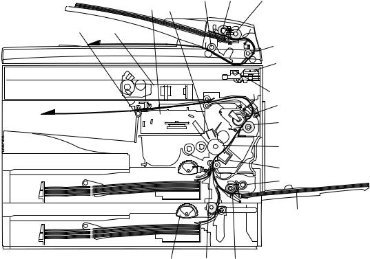
7. Cross sectional view
19 16 17
4 6
5 3
18
1
2
7
8
9
10
11
12
|
|
15 |
14 |
13 |
|
|
|
|
|
No. |
Part name |
|
Function and operation |
|
|
|
|
||
1 |
Scanner unit |
Illuminates the original with the copy lamp and passes the reflected light to the lens unit(CCD). |
||
|
|
|
|
|
2 |
Exposure lamp |
Exposure lamp (Xenon lamp) Illuminates original |
|
|
|
|
|
||
3 |
Lens unit |
Scans the original image with the lens and the CCD. |
||
|
|
|
||
4 |
LSU (Laser unit) |
Converts the original image signal into laser beams and writes onto the drum. |
||
|
|
|
|
|
5 |
Paper exit roller |
Roller for paper exit |
|
|
|
|
|
||
6 |
Main charger |
Provides negative charges evenly to the drum surface. |
||
|
|
|
|
|
7 |
Heat roller |
Fuses toner on the paper. (Teflon roller) |
|
|
|
|
|
|
|
8 |
Pressure roller |
Fuses toner on the paper. (Silicon rubber roller) |
|
|
|
|
|
|
|
9 |
Drum |
Forms images. |
|
|
|
|
|
|
|
10 |
Transfer unit |
Transfers images onto the drum. |
|
|
|
|
|
||
11 |
Pickup roller |
Picks up the manual feed paper. (In multi feed only) |
||
|
|
|
|
|
12 |
Manual paper feed tray |
Tray for manual feed paper |
|
|
|
|
|
||
13 |
Manual paper feed roller |
Transport the paper from the manual paper feed port. |
||
|
|
|
||
14 |
PS roller unit |
Takes synchronization between the lead edge and the rear edge of the paper. |
||
|
|
|
|
|
15 |
Paper feed roller |
Picks up a sheet of paper from the cassette. |
|
|
|
|
|
|
|
16 |
Pickup roller |
Picks up documents. |
|
|
|
|
|
|
|
17 |
Separation roller |
Separates documents to feed properly. |
|
|
|
|
|
|
|
18 |
PS roller |
Feeds documents to the scanning section. |
|
|
|
|
|
|
|
19 |
Paper exit roller |
Discharges documents. |
|
|
|
|
|
|
|
AL-1551 EXTERNAL VIEWS AND INTERNAL STRUCTURES 4-6

[5] UNPACKING AND INSTALLATION
1. Copier installation
Improper installation may damage the copier. Please note the following during initial installation and whenever the copier is moved.
Caution: If the copier is moved from a cool place to a warm place, condensation may form inside the copier. Operation in this condition will cause poor copy quality and malfunctions.
Leave the copier at room temperature for at least 2 hours before use.
Do not install your copier in areas that are:
• damp, humid, or very dusty
• exposed to direct sunlight
• poorly ventilated
•subject to extreme temperature or humidity changes, e.g., near an air conditioner or heater.
The copier should be installed near an accessible power outlet for easy connection.
Be sure to connect the power cord only to a power outlet that meets the specified voltage and current requirements.
Also make certain the outlet is properly grounded.
Be sure to allow the required space around the machine for servicing and proper ventilation.
+ |
8"(20cm) |
4" |
4" |
(10cm) |
(10cm) |
2. Cautions on handling
Be careful in handling the copier as follows to maintain the performance of this copier.
Do not drop the copier, subject it to shock or strike it against any object.
Do not expose the drum cartridge to direct sunlight.
Doing so will damage the surface (green portion) of the drum cartridge, causing poor print quality.
Store spare supplies such as drum cartridges and TD cartridges in a dark place without removing from the package before use.
If they are exposed to direct sunlight, poor print quality may result.
Do not touch the surface (green portion) of the drum cartridge.
Doing so will damage the surface of the cartridge, causing poor print quality.
AL-1551 UNPACKING AND INSTALLATION 5-1

3.Checking packed components and accessories
Open the carton and check if the following components and accessories are included.
Power cord |
Interface cable |
|
(IBM PC/AT or compatible computer) |
||
|
||
Operation manual |
|
|
Printer driver (CD-ROM) |
|
TD cartridge
Copier
Drum cartridge (installed in copier)
4. Unpacking
Be sure to hold the handles on both sides of the copier to unpack the copier and carry it to the installation location.
5. Removing protective packing materials
1)Remove pieces of tape and protective cover. Then open the original cover and remove protective materials (a) and (b).
6. Installing the TD cartridge
The TD cartridge replacement required ( ) indicator will light up when toner is needed. If copying is continued while the
  indicator is lit, copies will gradually become lighter until the copier stops and the indicator begins blinking. Replace the old TD cartridge by following the procedure given below.
Note:
•After the copier stops, it may be possible to make a few more copies by taking the TD cartridge out of the copier, shaking it horizontally, then reinstalling it. If copying is not possible after this operation, replace the TD cartridge.
•During long copy run of a dark original, the ready (  ) indicator may blink, the
  indicator may light up, and the copier may stop, even
though toner cartridge is not empty. The copier will feed toner up to 2 minutes and then the ready (  ) indicator will light up. Press the print (
  ) key to restart copying.
1)Ensure that the bypass tray is open and then open the side cover by pressing the open button on the side cover.
2)Remove the CAUTION tape from the front cover and remove the two protective pins from the fusing unit by pulling the strings upward one at a time.
CAUTION tape |
Protective pins |
|
3) Push gently on both sides of the front cover to open the cover.
2)Use a coin (or suitable object) to remove the screw.
Store the screw in the paper tray because it will be used if the copier
has to be moved.
AL-1551 UNPACKING AND INSTALLATION 5-2

4)Remove the TD cartridge from the bag. Remove the protective paper. Hold the cartridge on both sides and shake it horizontally four or five times.
4 or 5 times
5)Hold the tab of the protective cover and pull the tab to remove the cover.
6) Gently insert the TD cartridge until it locks in place.
7. Loading copy paper
Note:This copier is equipped with two paper trays. Load copy paper into the two paper trays.
1)Raise the handle of the paper tray and pull the paper tray out until it stops.
2)Remove the pressure plate lock. Rotate the pressure plate lock in the direction of the arrow to remove it while pressing down the pressure plate of the paper tray.
3)Store the pressure plate lock which has been removed in step 2 and the screw which has been removed when unpacking in the front of the paper tray. To store the pressure plate lock, rotate the lock to fix it on the relevant location.
4)Adjust the paper guides on the paper tray to the copy paper width and length.
Squeeze the lever of paper guide (A) and slide the guide to match with the width of the paper.
Move paper guide (B) to the appropriate slot as marked on the tray.
7)Close the front cover and then the side cover by pressing the round projections near the side cover open button. The  indicator will go
out and the ready (  ) indicator will light up.
Note: When closing the covers, be sure to close the front cover securely and then close the side cover. If the covers are closed in the wrong order, the covers may be damaged.
Paper guide (B) |
Paper guide (A) |
5)Fan the copy paper and insert it into the tray. Make sure the edges go under the corner hooks.
Note:Do not load paper above the maximum height line ( |
). |
Exceeding the line will cause a paper misfeed. |
|
6) Gently push the paper tray back into the copier.
Note:After loading copy paper, to cancel the blinking "H" without restarting copying, press the clear (  ) key. The "P" in the display will go out and the ready (
  ) indicator will light up.
AL-1551 UNPACKING AND INSTALLATION 5-3
8. Power to copier
1)Ensure that the power switch of the copier is in the OFF position. Insert the attached power cord into the power cord socket at the rear of the copier.
2)Plug the other end of the power cord into the nearest outlet.
9. Installing the printer driver
(Description of the printer driver)
The printer driver is the software program which runs the printer. It converts the data in your file into information that the printer can understand. It also controls communication between the printer and computer as the data is printed.
(Checking the hardware and software requirements)
You will need the following hardware and software in order to install the printer driver.
Computer type |
IBM PC/AT or compatible computer equipped with a |
|
bi-directional parallel interface and CD-ROM drive |
Windows type |
Windows 3.1x, Windows 95, Windows 98, |
|
Windows Me, Windows NT 4.0, Windows 2000 |
Display |
640 x 480 dots (VGA) or better |
Hard disk |
10 MB or more |
free space |
|
Hardware requirements, such as CPU performance rating and amount of RAM installed, are the same as for your operating system.
•The printer driver included in this product cannot be used under Windows NT 3.5x, OS/2, pure MS-DOS and other operating systems which are not described above.
•If you are using some of your computer’s memory as a RAM drive, the printer driver may not be allocated the correct amount of memory. In such a case, reduce the size of your RAM disk, or do not use the RAM disk. Please refer to your MS Windows documentation for further information.
(Installing the printer driver)
The software for your printer is provided on CD-ROM.
Before installing the printer driver, be sure to check the following items.
•Is the printer connected properly to the computer?
•Does the printer have paper?
•Is there another GDI printer driver or Windows Printing System printer driver already installed? If installed, change the printer port setting.
A. Windows 95/Windows NT 4.0
1)Load paper into the paper tray of the printer.
2)Turn on the printer.
3)Turn on your computer and start Windows.
•Before installing the printer driver, be sure to close all other applications which may be open.
4)When using Windows 95 on a personal computer with plug & play, the "Update Device Driver Wizard" window will appear. Insert the installation CD-ROM into the CD-ROM drive. Click the Next button and follow the on-screen instructions. If the "Copying Files" window appears during this operation, enter R:\ (substitute the letter of your CD-ROM drive for "R"), click the OK button and follow the on-screen instructions.
•If you are using Windows 95 and the "New Hardware Found" window will appear, select Driver from Disk Provided by Hardware Manufacturer and then click the OK button. Proceed to step 6.
•If you are using Windows 95 and the screen shown above or the "New Hardware Found" window does not appear, proceed to step 5.
•If you are using Windows NT 4.0, proceed to step 5.
*Plug & play
This feature is effective if both the computer and peripheral equipment are equipped with IEEE 1284 compliant parallel interface.
Note:The screen displayed depends on the version of Windows.
5)Insert the installation CD-ROM into the CD-ROM drive.
Click the Start button and select Run. When the screen shown below appears, type R:\SETUP(substitute the letter of your CD-ROM drive for "R") and click the OK button. Follow the on-screen instructions.
AL-1551 UNPACKING AND INSTALLATION 5-4
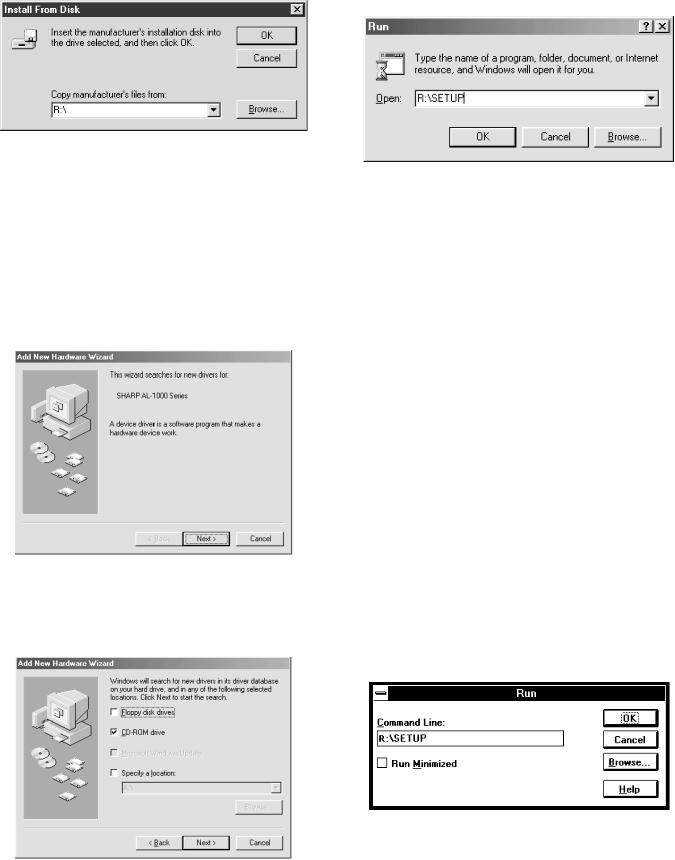
6)The "Install From Disk" window will appear. Insert the installation CDROM into the CD-ROM drive. Type R:\ (substitute the letter of your CD-ROM drive for "R") and click the OK button.
Follow the on-screen instructions.
8)Insert the installation CD-ROM into the CD-ROM drive. Click the Start button and select Run. When the window shown below appears, type R:\SETUP (substitute the letter of your CD-ROM drive for "R") and click the OK button.
Follow the on-screen instructions.
B. Windows 98:
1)Load paper into the paper tray of the printer.
2)Turn on the printer.
3)Turn on your computer and start Windows.
•Before installing the printer driver, be sure to close all other applications which may be open.
4)When using Windows 98 on a personal computer with plug & play, the "Add New Hardware Wizard" window will appear. Click the Next button and follow the on-screen instructions.
•If the "Add New Hardware Wizard" window does not ap-pear, proceed to step 8.
C. Windows Me/Windows 2000:
1)Load paper in the paper tray of the printer.
2)Turn on the printer.
3)Turn on your computer and start Windows.
•If a Plug & Play dialog box appears when you start Windows, click the Cancel button to close the dialog box.
•Before installing the printer driver, be sure to close all other applications which may be open.
4)Insert the installation CD-ROM into the CD-ROM drive. Click the Start button and select Run. Type R:\SETUP (substitute the letter of your CD-ROM drive for "R") and click the OK button. Follow the onscreen instructions.
•If the "Found New Hardware Wizard" window appears when you start Windows after installing the printer driver, click the Finish button.
5)Select Search for the best driver for your device and click the Next button.
6)Insert the installation CD-ROM into the CD-ROM drive. Select CD-ROM drive and click the Next button.
7)Windows driver file search will find the device “SHARP AL-1000 Series”. Click the Next button and follow the on-screen instructions.
D. Windows 3.1x:
1)Load paper into the paper tray of the printer.
2)Turn on the printer and then start Windows on your computer.
•Before installing the printer driver, be sure to close all other applications which may be open.
3)Insert the installation CD-ROM into a CD-ROM drive.
4)Choose File from the Menu bar in Program Manager, and then choose the Run... command.
5)Type R:\SETUP (substitute the letter of your CD-ROM drive for "R") in the command line box and then click the OK button..
6) Follow the on-screen instructions.
AL-1551 UNPACKING AND INSTALLATION 5-5

E. AL-1000 Series printer driver group
When the printer driver is installed, the SHARP AL-1000 Series printer driver group will be created. This group allows the following functions to be executed.
Uninstall AL-1000 Series
The printer driver can be uninstalled. If the driver is uninstalled, printing cannot be performed on the printer. For proper uninstallation, be sure to use uninstallation program of the printer driver group.
Readme
The latest information on the printer driver is included in this note. Read the Readme first.
Advanced Settings
See help for application support and application problems that may occur when printing. See help for the applicable method of usage.
Status Monitor
The printer state and information on current printing are displayed on the status monitor window.
DOS Emulation Setup
Status Monitor HELP
DOS Emulation HELP
Advanced Settings HELP
•Be sure to read "Readme" found in the printer driver group before starting to print from application programs.
10.Parallel interface
This printer uses a bi-directional parallel interface. Use the sup-plied interface cable.
Connector
36-pin DDK 57LE-40360-730B (D29) female connector or equivalent connector
Cable
Shielded type bi-directional parallel interface For best results, use a printer interface cable which is IEEE1284 compliant.
Pin configuration
The pin numbers and signal names are listed in the follow-ing table.
18 |
1 |
|
36 |
|
|
|
19 |
|
|
|
|
|||
|
|
|
|
|
|
|
|
|
|
|
|
|
Pin No. |
|
Signal name |
Pin No. |
|
Signal name |
|||||||
|
|
|
|
|
|
|
|
|
|
|
|
|
|
|
|
|
|
|
|
|
|
|
|||
1 |
STB |
19 |
GND (STB RET) |
|||||||||
|
|
|
|
|
|
|
|
|
|
|
|
|
2 |
DATA1 |
20 |
GND (DATA1 RET) |
|||||||||
|
|
|
|
|
|
|
|
|
|
|
|
|
3 |
DATA2 |
21 |
GND (DATA2 RET) |
|||||||||
|
|
|
|
|
|
|
|
|
|
|
|
|
4 |
DATA3 |
22 |
GND (DATA3 RET) |
|||||||||
|
|
|
|
|
|
|
|
|
|
|
|
|
5 |
DATA4 |
23 |
GND (DATA4 RET) |
|||||||||
|
|
|
|
|
|
|
|
|
|
|
|
|
6 |
DATA5 |
24 |
GND (DATA5 RET) |
|||||||||
|
|
|
|
|
|
|
|
|
|
|
|
|
7 |
DATA6 |
25 |
GND (DATA6 RET) |
|||||||||
|
|
|
|
|
|
|
|
|
|
|
|
|
8 |
DATA7 |
26 |
GND (DATA7 RET) |
|||||||||
|
|
|
|
|
|
|
|
|
|
|
|
|
9 |
DATA8 |
27 |
GND (DATA8 RET) |
|||||||||
|
|
|
|
|
|
|
|
|
|
|
|
|
10 |
|
|
|
|
28 |
GND |
||||||
|
|
|
|
|
|
|
|
|
|
|||
ACKNLG |
(ACKNLG RET) |
|||||||||||
|
|
|||||||||||
|
|
|
|
|
|
|
|
|
|
|
|
|
11 |
BUSY |
29 |
GND (BUSY RET) |
|||||||||
|
|
|
|
|
|
|
|
|
|
|
|
|
12 |
PE (Paper End) |
30 |
GND (PE RET) |
|||||||||
|
|
|
|
|
|
|
|
|
|
|
|
|
13 |
SLTC |
31 |
INPRM |
|||||||||
|
|
|
|
|
|
|
|
|
|
|
|
|
|
|
|
|
|
|
|||||||
14 |
AUTO LF |
32 |
FAULT |
|
|
|||||||
|
|
|
|
|
|
|
|
|
|
|
|
|
15 |
(NC) |
33 |
(NC) |
|||||||||
|
|
|
|
|
|
|
|
|
|
|
|
|
16 |
GND (0 V) |
34 |
(NC) |
|||||||||
|
|
|
|
|
|
|
|
|
|
|
|
|
17 |
FG |
35 |
+5 V |
|||||||||
|
|
|
|
|
|
|
|
|
|
|
|
|
|
|
|
|
|
||||||||
18 |
+5 V |
36 |
SLTC IN |
|||||||||
|
|
|
|
|
|
|
|
|
|
|
|
|
AL-1551 UNPACKING AND INSTALLATION 5-6

[6] COPY PROCESS
An OPC drum is used for the photoconductor.
(Structure of the OPC drum layers)
OPC layer
(20microns thick)
Pigment layer (0.2 to 0.3 microns thick) Aluminium drum
1. Functional diagram
Main charger |
|
Laser beam |
Cleaning blade |
MG roller |
Drum |
|
|
|
|
|
Transfer unit |
|
|
|
|
|
|
Resist roller |
|
||
(Basic operation cycle) |
|
|
|
|
|
||
|
|
|
Semiconductor laser |
|
|
||
|
|
|
|
Focus correction lens |
|
||
|
|
Main high voltage unit |
|
Exposure |
|
|
|
|
|
|
|
|
|
||
|
|
Saw tooth |
Charge |
|
|
|
|
|
|
|
|
|
|
Toner |
|
|
|
|
|
Drum |
Developing |
Developer |
|
|
|
|
Cleaning |
|
|
||
|
|
|
|
|
|
||
|
Cleaning blade |
|
|
|
|
||
|
|
Waste toner box |
|
|
|
PS roller |
|
To face |
Paper release |
Fusing |
Separation |
Transfer |
Synchronization |
Manual feed |
|
down tray |
with drum |
||||||
|
|
|
|
|
|||
|
|
Heat roller |
Electrode |
Transfer charger |
Cassette |
|
|
|
|
|
|
|
|
||
|
|
|
|
|
paper feed |
|
|
|
|
Heater lamp |
|
Transfer high |
|
|
|
|
|
|
|
voltage unit |
|
Print process |
|
|
|
|
|
|
|
||
Paper transport route
AL-1551 COPY PROCESS 6-1

2. Outline of print process
This printer is a non-impact printer that uses a semiconductor laser and electrostatic print process. This printer uses an OPC (Organic Photo Conductor) for its photoconductive material.
First, voltage from the main corona unit charges the drum surface and a latent image is formed on the drum surface using a laser beam. This latent image forms a visible image on the drum surface when toner is applied. The toner image is then transferred onto the print paper by the transfer corona and fused on the print paper in the fusing section with a combination of heat and pressure.
Step-1: Charge
Step-2: Exposure
* Latent image is formed on the drum. Step-3: Developing
Latent image formed on the drum is then changed into visible image with toner.
Step-4: Transfer
The visible image (toner image) on the drum is transferred onto the print paper.
Step-5: Cleaning
Residual toner on the drum surface is removed and collected by the cleaning blade.
Step-6: Optical discharge
Residual charge on the drum surface is removed, by semiconductor laser beam.
3. Actual print process
Step-1: DC charge
A uniform negative charge is applied over the OPC drum surface by the main charging unit. Stable potential is maintained by means of the Scorotron charger.
Positive charges are generated in the aluminum layer.
About
DC5.5KV
( 580V/ 400V)
Step-2: Exposure (laser beam, lens)
A Laser beam is generated from the semiconductor laser and controlled by the print pattern signal. The laser writes onto the OPC drum surface through the polygon mirrors and lens. The resistance of the OPC layer decreases for an area exposed by the laser beam (corresponding to the print pattern signal). The beam neutralizes the negative charge. An electrostatic latent image is formed on the drum surface.
Semiconductor laser
Exposure (semiconductor laser)
OPC layer Pigment layer
Aluminum drum
Drum surface charge sfter the exposure
OPC layer Pigment layer
Aluminum
layer
Non-image area Image area
AL-1551 COPY PROCESS 6-2

Step-3: Developing (DC bias)
A bias potential is applied to the MG roller in the two component magnetic brush developing method, and the toner is charged negative through friction with the carrier.
Non-image area of the drum surface charged with negative potential repel the toner, whereas the laser exposed portions where no negative charges exist, attract the toner. As a result, a visible image appears on the drum surface.
 :Carrier (Magnetized particle)
  :Toner (Charge negative by friction)
(N)(S) Permanent magnet (provided in three locations)
N
S
N
MG roller
DC
400V 8V
8V
Step-4: Transfer
The visible image on the drum surface is transferred onto the print paper by applying a positive charge from the transfer corona to the backside of the print paper.
About DC 5.2kV
Step-5: Separation
Since the print paper is charged positively by the transfer corona, it is discharged by the separation corona. The separation corona is connected to ground.
Step-6: Cleaning
Toner remaining on the drum is removed and collected by the cleaning blade. It is transported to the waste toner collecting section in the cleaning unit by the waste toner transport roller.
Toner is attracted over the shadowed area because of the developing bias.
AL-1551 COPY PROCESS 6-3
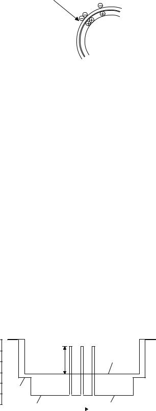
Step-7: Optical discharge (Semiconductor laser)
Before the drum rotation is stopped, the semiconductor laser is radiated onto the drum to reduce the electrical resistance in the OPC layer and elimate residual charge, providing a uniform state to the drum surface for the next page to be printed.
When the electrical resistance is reduced, positive charges on the aluminum layer are moved and neutralized with negative charges on the OPC layer.
Semiconductor laser
Charge by the Scorotron charger
Function
The Scorotron charger functions to maintain uniform surface potential on the drum at all times, It control the surface potential regardless of the charge characteristics of the photoconductor.
Basic function
A screen grid is placed between the saw tooth and the photoconductor. A stable voltage is added to the screen grid to maintain the corona current on the photoconductor.
As the photoconductor is charged by the saw tooth from the main corona unit, the surface potential increases. This increases the current flowing through the screen grid. When the photoconductor potential nears the grid potential, the current turns to flow to the grid so that the photoconductor potential can be maintained at a stable level.
Process controlling
Function
The print pattern signal is converted into an invisible image by the semiconductor laser using negative to positive (reversible) developing method. Therefore, if the developing bias is added before the drum is charged, toner is attracted onto the drum. If the developing bias is not added when the drum is charged, the carrier is attracted to the drum because of the strong electrostatic force of the drum.
To avoid this, the process is controlled by adjusting the drum potential and the grid potential of the Scorotron charger.
Basic function
Voltage added to the screen grid can be selected, high and low. To make it easily understood, the figure below shows voltage transition at the developer unit.
START |
STOP |
0
Print potentioal
|
Toner attract |
Developing bias |
|
potential |
|
|
|
|
|
2) |
|
|
3) |
|
1) |
Low |
|
4) High |
|
Drum potential |
|
|
|
|
|
|
|
Time |
|
Start
1)Because the grid potential is at a low level, the drum potential is at about -400V. (Carrier may not be attracted though the carrier is pulled towards the drum by the electrostatic force of -400V.
2)Developing bias (-400V) is applied when the photoconductor potential is switched from LOW to HIGH.
3)Once developing bias (-400V) is applied and the photo conductor potential rises to HIGH, toner will not be attracted to the drum.
Stop
The reverse sequence takes place.
Retaining developing bias at an abnormal occurrence
Function
The developing bias will be lost if the power supply was removed during print process. In this event, the drum potential slightly abates and the carrier makes deposits on the drum because of strong static power. To prevent this, the machine incorporates a function to retain the developing bias for a certain period and decrease the voltage gradually against possible power loss.
Basic function
Normally, the developing bias voltage is retained for a certain time before the drum comes to a complete stop if the machine should stop before completing the normal print cycle. The developing bias can be added before resuming the operation after an abnormal interruption. Therfore, carrier will not make a deposit on the drum surface.
AL-1551 COPY PROCESS 6-4
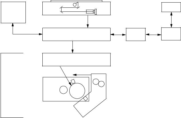
[7] OPERATIONAL DESCRIPTIONS
1. Outline of operation
The outline of operation is described referring to the basic configuration.
(Basic configuration)
Scanner section
CCD |
PC |
Operation
section
MCU (Main control/image process section) |
PCL control |
PCL I / F |
LSU (Laser unit)
Laser diode, Polygon mirror lens
Laser beam
Paper exit
Fusing section
Process section
Printer section
Paper transport section
|
|
Manual paper |
Cassette paper |
|
|
feed section |
|
feed section |
|
|
|
(Outline of copy operation)
Setting conditions
1) Set copy conditions such as the copy quantity and the copy density with the operation section, and press the COPY button. The information on copy conditions is sent to the MCU.
Image scanning
2)When the COPY button is pressed, the scanner section starts scanning of images.
The light from the copy lamp is reflected by the document and passed through the lens to the CCD.
Photo signal/Electric signal conversion
3)The image is converted into electrical signals by the CCD circuit and passed to the MCU.
Image process
4)The document image signal sent from the CCD circuit is processed under the revised conditions and sent to the LSU (laser unit) as print data.
Electric signal/Photo signal (laser beam) conversion
5)The LSU emits laser beams according to the print data. (Electrical signals are converted into photo signals.)
6)The laser beams are radiated through the polygon mirror and various lenses to the OPC drum.
Printing
7)Electrostatic latent images are formed on the OPC drum according to the laser beams, and the latent images are developed to be visible images(toner images).
8)Meanwhile the paper is fed to the image transfer section in synchronization with the image lead edge.
9)After the transfer of toner images onto the paper, the toner images are fused to the paper by the fusing section. The copied paper is discharged onto the exit tray.
AL-1551 OPERATIONAL DESCRIPTIONS 7-1

2. Scanner section
A. How to scan documents
The scanner has sensors that are arranged in a line. These sensors scan a certain area of a document at a time and deliver outputs sequentially. When the line is finished, the next line is scanned, and this procedure is repeated.
The figure below shows the case where the latter two sections of an image which are scanned are shown with solid lines and the former two sections which are being transmitted are shown with dotted lines.
The direction of this line is called "main scanning direction," and the scanning direction "sub scanning direction."
In the figure below, one line is divided into 4 sections. Actually, however, one line is divided into thousands of sections. For scanning, the light receiving element called CCD is used.
The basic resolution indicates the scanner capacity. The basic resolution is expressed in dpi (dot/inch) which shows the number of light emitting elements per inch on the document.
The basic resolution of this machine is 400dpi.
In the sub scanning direction, at the same time, the motor that drives the optical system is controlled to scan the image at the basic resolution.
 Sub scanning direction
 Sensor scanning area
Main scanning direction
Original
1
2
3
4
5
Image data sent to the ICU PWB
5 |
4 |
3 |
2 |
1 |
To MCU PWB
B. Basic structure of scanner section
(11) |
(4) |
(1) |
(2) |
(8) |
|
|
|
|
|||
|
|
|
|
|
|
|
|
|
|
|
|
|
|
|
|
|
|
|
|
|
|
|
|
|
|
|
|
|
|
|
|
|
|
|
|
|
|
|
|
|
|
|
|
|
|
|
|
|
|
|
|
|
|
|
|
|
|
|
|
|
|
|
|
|
|
|
|
|
|
|
|
|
|
|
|
|
|
|
|
|
|
|
|
(5) (7) (3) (6) (9) (10)
1 |
Copy lamp (Xenon lamp) |
2 |
Reflector |
|
|
|
(light conversion plate) |
3 |
No. 1 mirror |
4 |
No. 2 mirror |
5 |
No. 3 mirror |
6 |
Lens |
7 |
No. 2/3 mirror unit |
8 |
Copy lamp unit |
9 |
CCD |
10 |
Mirror motor |
11 |
MHPS |
|
|
|
(Mirror home position sensor) |
|
|
The scanner unit performs scanning in the digital optical system.
The light from the light source (Xenon lamp) is reflected by a document and passed through three mirrors and reduction lenses to the CCD element (image sensor) where images are formed. This system is known as the reduction image sensor system. Photo energy on the CCD element is converted into electrical signals (analog signals). (Photoelectric conversion). The output signals (analog signals) are converted into digital signals (A/D conversion) and passed to the MCU (main control/image process section). The resolution at that time is 400dpi.
The mirror unit in the scanner section is driven by the mirror motor.
The MHPS is provided to detect the home position of the copy lamp unit.
AL-1551 OPERATIONAL DESCRIPTIONS 7-2
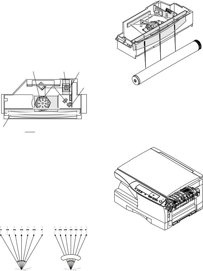
3. Laser unit
The image data sent from the MCU (image process circuit) is sent to the LSU (laser unit), where it is converted into laser beams.
A. Basic structure
The LSU unit is the writing section of the digital optical system.
The semiconductor laser is used as the light source, and images are formed on the OPC drum by the polygon mirror and fθ lens, etc.
The laser beams are passed through the collimator lens, the cylindrical lens, the polygon mirror, the fθ lens, and the mirror to form images on the OPC drum in the main scanning direction. The laser emitting PWB is provided with the APC (auto power control) in order to eliminate fluctuations in the laser power. The BF PWB works for measurement of the laser writing start point.
(3) |
(2) |
(1) |
(4)
(5)
|
|
: Laser beam |
|
|
path for BF PWB |
|
|
|
No |
Component |
Function |
|
|
|
(1) |
Semiconductor laser |
Generates laser beams. |
|
|
|
(2) |
Collimator lens |
Converges laser beams in parallel. |
|
|
|
(3) |
Polygon mirror, |
Reflects laser beams at a constant rpm. |
|
polygon motor |
|
|
|
|
(4) |
BD (Mirror, lens, PWB) |
Detects start timing of laser scanning. |
|
|
|
(5) |
fθ lens |
Converges laser beams at a spot on the |
|
|
drum. |
|
|
|
|
|
Makes the laser scanning speeds at both |
|
|
ends of the drum same as each other. |
|
|
(Refer to the figure below.) |
|
|
|
Makes the laser scanning speeds at both ends of the drum same as each other.
|
|
a ≠ b ≠ c |
|
|
|
|
|
d = e = f |
|
|
|
|
|
|
|
|
|
|
|||
|
|
a b c |
|
|
|
d e f |
||||
|
|
|
|
|
|
|
|
|
|
|
|
|
|
|
|
|
|
|
|
|
|
fθ LENS
B. Laser beam path
C. Composition
Effective scanning width:216mm (max.) Resolution:600dpi
Beam diameter: 75um in the main scanning direction, 80um in the sub scanning direction
Image surface power:0.20 ±0.03mW (Laser wavelength 780 - 795nm) Polygon motor section:Brushless motor 20.787rpm
No. of mirror surfaces:6 surfaces
4. Fuser section
AL-1551 OPERATIONAL DESCRIPTIONS 7-3
 Loading...