


SERVICE MANUAL
CODE : 00ZAL1457/A1E
DIGITAL LASER COPIER/
DIGITAL MULTIFUNCTIONAL
SYSTEM
AL-1217
MODEL AL-1457
CONTENTS
[ 1 ] GENERAL . . . . . . . . . . . . . . . . . . . . . . . . . . . . . . . . . . . . . . . . . . . 1 - 1 [ 2 ] SPECIFICATIONS. . . . . . . . . . . . . . . . . . . . . . . . . . . . . . . . . . . . . 2 - 1
[ 3 ] CONSUMABLE PARTS. . . . . . . . . . . . . . . . . . . . . . . . . . . . . . . . . 3 - 1
[ 4 ] EXTERNAL VIEWS AND INTERNAL STRUCTURES . . . . . . . . . 4 - 1 [ 5 ] UNPACKING AND INSTALLATION . . . . . . . . . . . . . . . . . . . . . . . 5 - 1
[ 6 ] COPY PROCESS . . . . . . . . . . . . . . . . . . . . . . . . . . . . . . . . . . . . . 6 - 1
[ 7 ] OPERATIONAL DESCRIPTIONS . . . . . . . . . . . . . . . . . . . . . . . . . 7 - 1
[ 8 ] DISASSEMBLY AND ASSEMBLY . . . . . . . . . . . . . . . . . . . . . . . . 8 - 1 [ 9 ] ADJUSTMENTS . . . . . . . . . . . . . . . . . . . . . . . . . . . . . . . . . . . . . . 9 - 1
[10] SIMULATION, TROUBLE CODES . . . . . . . . . . . . . . . . . . . . . . . 10 - 1
[11] USER PROGRAMS. . . . . . . . . . . . . . . . . . . . . . . . . . . . . . . . . . . 11 - 1 [12] ELECTRICAL SECTION . . . . . . . . . . . . . . . . . . . . . . . . . . . . . . . 12 - 1
[13] CIRCUIT DIAGRAM . . . . . . . . . . . . . . . . . . . . . . . . . . . . . . . . . . 13 - 1
Parts marked with “ ” are important for maintaining the safety of the machine. Be sure to replace these parts with the replacement parts specified to maintain the safety and performance of the machine.
This document has been published to be used
SHARP CORPORATION |
for after sales service only. |
|
|
|
The contents are subject to change without notice. |

CAUTION
This product is a class 1 laser product that complies with 21CFR 1040 of the CDRH standard and IEC825. This means that this machine does not produce hazardous laser radiation. The use of controls, adjustments or performance of procedures other than those specified herein may result in hazardous radiation exposure.
This laser radiation is not a danger to the skin, but when an exact focusing of the laser beam is achieved on the eye’s retina, there is the danger of spot damage to the retina.
The following cautions must be observed to avoid exposure of the laser beam to your eyes at the time of servicing.
1)When a problem in the laser optical unit has occurred, the whole optical unit must be exchanged as a unit, not as individual parts.
2)Do not look into the machine with the main switch turned on after removing the developer unit, toner cartridge, and drum cartridge.
3)Do not look into the laser beam exposure slit of the laser optical unit with the connector connected when removing and installing the optical system.
4)The middle frame contains the safety interlock switch.
Do not defeat the safety interlock by inserting wedges or other items into the switch slot.
LASER WAVE – LENGTH : 770 ~ 795nm Pulse times : 11.82µs/7mm
Out put power : 0.17mW ± 0.01mW
CAUTION
INVISIBLE LASER RADIATION,
WHEN OPEN AND INTERLOCKS DEFEATED.
AVOID EXPOSURE TO BEAM.
VORSICHT
UNSICHTBARE LASERSTRAHLUNG, WENN ABDECKUNG GEÖFFNET UND
SICHERHEITSVERRIEGELUNG ÜBERBRÜCKT. NICHT DEM STRAHL AUSSETZEN.
VARO !
AVATTAESSA JA SUOJALUKITUS
OHITETTAESSA OLET ALTTIINA NÄKYMÄTTÖMÄLLE LASERSÄTEILYLLE ÄLÄ KATSO SÄTEESEEN.
ADVARSEL
USYNLIG LASERSTRÅLNING VED ÅBNING, NÅR SIKKERHEDSBRYDERE ER UDE AF FUNKTION. UNDGÅ UDSAETTELSE FOR STRÅLNING.
VARNING !
OSYNLIG LASERSTRÅLNING NÄR DENNA DEL ÄR ÖPPNAD OCH SPÄRREN ÄR URKOPPLAD. BETRAKTA EJ STRÅLEN. – STRÅLEN ÄR FARLIG.

At the production line, the output power of the scanner unit is adjusted to 0.57 MILLI-WATT PLUS 20 PCTS and is maintained constant by the operation of the Automatic Power Control (APC). Even if the APC circuit fails in operation for some reason, the maximum output power will only be 15 MILLI-WATT 0.1 MICRO-SEC. Giving and accessible emission level of 42 MICRO-WATT which is still-less than the limit of CLASS-1 laser product.
Caution
This product contains a low power laser device. To ensure continued safety do not remove any cover or attempt to gain access to the inside of the product. Refer all servicing to qualified personnel.
Caution label on the unit
The label ( 
 ) in the fusing area of the unit indicates the following:
  : Caution, risk of danger
 : Caution, hot surface
VAROITUS! LAITTEEN KÄYTTÄMINEN MUULLA
KUIN TÄSSÄ KÄYTTÖOHJEESSA MAINITULLA
TAVALLA SAATTAA ALTISTAA KÄYTTÄJÄN
TURVALLISUUSLUOKAN 1 YLITTÄVÄLLE
NÄKYMÄTTÖMÄLLE LASERSÄTEILYLLE.
VARNING - OM APPARATEN ANVÄNDS PÅ ANNAT SÄTT ÄN I DENNA BRUKSANVISNING SPECIFICERATS, KAN ANVÄNDAREN UTSÄTTAS FÖR OSYNLIG LASERSTRÅLNING, SOM ÖVERSKRIDER GRÄNSEN FÖR LASERKLASS 1.
|
|
|
|
|
|
|
|
|
|
LUOKAN 1 LASERLAITE |
|
The foregoing is applicable only to the 220V |
|||||
|
|
|
KLASS 1 LASER APPARAT |
||
model, 230V model and 240V model. |
|
|
|
|
|
|
|
|
|
CONTENTS
[1]GENERAL
1. Major functions . . . . . . . . . . . . . . . . . . . . . . . . . . . . . . . . . |
1-1 |
[2]SPECIFICATIONS
1. Basic Specifications. . . . . . . . . . . . . . . . . . . . . . . . . . . . . . 2-1 2. Operation specifications . . . . . . . . . . . . . . . . . . . . . . . . . . 2-1 3. Copy performance . . . . . . . . . . . . . . . . . . . . . . . . . . . . . . . 2-3 4. GDI Printer. . . . . . . . . . . . . . . . . . . . . . . . . . . . . . . . . . . . . 2-4 5. Scan function. . . . . . . . . . . . . . . . . . . . . . . . . . . . . . . . . . . 2-4 6. SPF . . . . . . . . . . . . . . . . . . . . . . . . . . . . . . . . . . . . . . . . . . 2-4
[3]CONSUMABLE PARTS
1. Supply system table . . . . . . . . . . . . . . . . . . . . . . . . . . . . . 3-1 2. Environmental . . . . . . . . . . . . . . . . . . . . . . . . . . . . . . . . . . 3-1 3. Production control number (lot No.) identification . . . . . . . 3-2
[4]EXTERNAL VIEWS AND INTERNAL STRUCTURES
1. Appearance . . . . . . . . . . . . . . . . . . . . . . . . . . . . . . . . . . . . 4-1 2. Internal. . . . . . . . . . . . . . . . . . . . . . . . . . . . . . . . . . . . . . . . 4-1 3. Operation panel . . . . . . . . . . . . . . . . . . . . . . . . . . . . . . . . . 4-2 4. Motors and solenoids . . . . . . . . . . . . . . . . . . . . . . . . . . . . 4-4 5. Sensors and switches . . . . . . . . . . . . . . . . . . . . . . . . . . . . 4-5 6. PWB unit . . . . . . . . . . . . . . . . . . . . . . . . . . . . . . . . . . . . . . 4-6 7. Cross sectional view . . . . . . . . . . . . . . . . . . . . . . . . . . . . . 4-7
[5]UNPACKING AND INSTALLATION
1. Copier installation . . . . . . . . . . . . . . . . . . . . . . . . . . . . . . . 5-1 2. Cautions on handling. . . . . . . . . . . . . . . . . . . . . . . . . . . . . 5-1 3. Checking packed components and accessories . . . . . . . . 5-1 4. Unpacking . . . . . . . . . . . . . . . . . . . . . . . . . . . . . . . . . . . . . 5-2 5. Removing protective packing materials . . . . . . . . . . . . . . . 5-2 6. Installing the TD cartridge . . . . . . . . . . . . . . . . . . . . . . . . . 5-2 7. Loading copy paper . . . . . . . . . . . . . . . . . . . . . . . . . . . . . . 5-3 8. Power to copier . . . . . . . . . . . . . . . . . . . . . . . . . . . . . . . . . 5-3 9. Software for the SHARP personal MFP series . . . . . . . . . 5-3 10. Connecting the interface cable . . . . . . . . . . . . . . . . . . . . . 5-8 11. Parallel interface . . . . . . . . . . . . . . . . . . . . . . . . . . . . . . . . 5-8 12. USB interface . . . . . . . . . . . . . . . . . . . . . . . . . . . . . . . . . . 5-9 13. Moving . . . . . . . . . . . . . . . . . . . . . . . . . . . . . . . . . . . . . . . . 5-9
[6]COPY PROCESS
1. Functional diagram . . . . . . . . . . . . . . . . . . . . . . . . . . . . . . 6-1 2. Outline of print process . . . . . . . . . . . . . . . . . . . . . . . . . . . 6-2 3. Actual print process . . . . . . . . . . . . . . . . . . . . . . . . . . . . . . 6-2
[7]OPERATIONAL DESCRIPTIONS
1. Outline of operation . . . . . . . . . . . . . . . . . . . . . . . . . . . . . . .7-1 2. Scanner section . . . . . . . . . . . . . . . . . . . . . . . . . . . . . . . . .7-2 3. Laser unit . . . . . . . . . . . . . . . . . . . . . . . . . . . . . . . . . . . . . .7-3 4. Fuser section. . . . . . . . . . . . . . . . . . . . . . . . . . . . . . . . . . . .7-3 5. Paper feed section and paper transport section . . . . . . . . .7-4 6. Process unit new drum detection mechanism. . . . . . . . . . .7-7 7. SPF section . . . . . . . . . . . . . . . . . . . . . . . . . . . . . . . . . . . . .7-7
[8]DISASSEMBLY AND ASSEMBLY
1. High voltage section . . . . . . . . . . . . . . . . . . . . . . . . . . . . . .8-1 2. Operation panel section . . . . . . . . . . . . . . . . . . . . . . . . . . .8-2 3. Optical section. . . . . . . . . . . . . . . . . . . . . . . . . . . . . . . . . . .8-3 4. Fusing section . . . . . . . . . . . . . . . . . . . . . . . . . . . . . . . . . . .8-5 5. Tray paper feed/transport section . . . . . . . . . . . . . . . . . . . .8-7 6. Manual paper feed section . . . . . . . . . . . . . . . . . . . . . . . .8-13 7. Rear frame section . . . . . . . . . . . . . . . . . . . . . . . . . . . . . .8-17 8. Power section . . . . . . . . . . . . . . . . . . . . . . . . . . . . . . . . . .8-18 9. SPF section (SPF model only) . . . . . . . . . . . . . . . . . . . . .8-18
[9] ADJUSTMENTS
1. Optical section. . . . . . . . . . . . . . . . . . . . . . . . . . . . . . . . . . .9-1 2. Copy density adjustment . . . . . . . . . . . . . . . . . . . . . . . . . . .9-4 3. High voltage adjustment . . . . . . . . . . . . . . . . . . . . . . . . . . .9-5
[10] SIMULATION, TROUBLE CODES
1. Entering the simulation mode . . . . . . . . . . . . . . . . . . . . . .10-1 2. List of simulations . . . . . . . . . . . . . . . . . . . . . . . . . . . . . . .10-2 3. Contents of simulations . . . . . . . . . . . . . . . . . . . . . . . . . . .10-3 4. Trouble codes . . . . . . . . . . . . . . . . . . . . . . . . . . . . . . . . .10-14
[11] USER PROGRAMS
1. Functions that can be set with user programs. . . . . . . . . .11-1 2. Change the setting . . . . . . . . . . . . . . . . . . . . . . . . . . . . . .11-1 3. Density level adjustment . . . . . . . . . . . . . . . . . . . . . . . . . .11-2 4. Toner save mode setup and cancel . . . . . . . . . . . . . . . . .11-2
[12] ELECTRICAL SECTION
1. Block diagram . . . . . . . . . . . . . . . . . . . . . . . . . . . . . . . . . .12-1 2. Circuit descriptions . . . . . . . . . . . . . . . . . . . . . . . . . . . . . .12-3
[13] CIRCUIT DIAGRAM
1. MCU PWB . . . . . . . . . . . . . . . . . . . . . . . . . . . . . . . . . . . . .13-1 2. OPERATION PWB . . . . . . . . . . . . . . . . . . . . . . . . . . . . .13-10 3. I/F PWB . . . . . . . . . . . . . . . . . . . . . . . . . . . . . . . . . . . . . .13-11 4. POWER SUPPLY . . . . . . . . . . . . . . . . . . . . . . . . . . . . . .13-12 5. NOISE FILTER CIRCUIT . . . . . . . . . . . . . . . . . . . . . . . .13-12 6. ACTUAL WIRING DIAGRAM . . . . . . . . . . . . . . . . . . . . .13-14
[1] GENERAL
1. Major functions
Configurations
|
Item |
|
|
|
Color |
GDI |
PCL |
|
|
|
CPM |
SB/MB 2 Tray |
SPF |
R-SPF |
SOPM Duplex Memory |
FAX |
|||
|
Scanner |
printer |
printer |
||||||
Model |
|
|
|
|
|
|
|||
|
|
|
|
|
|
|
|
|
|
AL-1217 |
12CPM |
SB |
|
|
|
|
|
8M |
|
AL-1457 |
14CPM |
MB |
|
|
|
|
|
8M |
|
Descriptions of items
CPM: |
Copy speed (Copies Per Minute) |
SB/MB: |
SB = Manual feed single bypass, MB = Manual feed multi bypass |
2 tray: |
Second cassette unit. |
SPF: |
Original feed unit |
R-SPF: |
Duplex original feed unit |
Color scanner: |
Color scanner function |
GDI printer: |
GDI printer function with USB. |
PCL printer: |
PCL printer function with USB. |
SOPM: |
Scan Once Print Many function (Many copies are made by one scan.) |
Duplex: |
Auto duplex copy function |
Memory: |
Standard page memory |
FAX: |
FAX function. |
Descriptions of table
 : Standard provision
 : No function or no option available
AL-1217
AL-1457
AL-1457 GENERAL 1 - 1
[2] SPECIFICATIONS
1. Basic Specifications
Item |
|
|
|
|
|
|
|
Type |
|
Desktop |
|
|
|
|
|
Copy system |
|
Dry, electrostatic |
|
|
|
|
|
Segment (class) |
|
Digital personal copier |
|
|
|
|
|
Copier dimensions |
AL-1217 |
20.4"(W)X18.2"(D)X11.6"(H) (518mm(W)X462.5mm(D)X295.6mm(H)) |
|
|
|
|
|
|
AL-1457 |
20.4"(W)X19.4"(D)X15.0"(H) (518mm(W)X492.5mm(D)X380.4mm(H)) |
|
|
|
|
|
Weight |
AL-1217 |
35.3lbs.(17Kg) |
TD and drum cartridges included |
(Approximately) |
|
|
|
AL-1457 |
41.9lbs.(20Kg) |
|
|
|
|
|
|
2. Operation specifications
|
Section, item |
Details |
|
|
|
|
|
|
|
Paper feed |
Paper feed |
|
AL-1217 |
1 tray (250 sheet) + single bypass |
section |
system |
|
|
|
|
AL-1457 |
1 tray (250 sheet) + multi bypass (50 sheet) |
||
|
|
|
|
|
|
AB system |
Tray paper feed |
Paper size |
A4, B5, A5 (Landscape) |
|
|
section |
|
|
|
|
Paper weight |
56 - 80g/m2 (15 - 21 lbs.) |
|
|
|
|
Paper feed capacity |
250 sheets |
|
|
|
|
|
|
|
|
Kinds |
Standard paper, specified paper, recycled paper |
|
|
|
|
|
|
|
|
Remark |
User adjustment of paper guide available |
|
|
|
|
|
|
|
Multi bypass paper |
Paper size |
A4, B5, A5, B6, A6 (Landscape) |
|
|
feed section |
|
|
|
|
Paper weight |
52 - 128g/m2 (14 - 34.5 lbs.) |
|
|
|
|
Paper feed capacity |
50 sheets |
|
|
|
|
|
|
|
|
Kinds |
Standard paper, specified paper, recycled paper, OHP, |
|
|
|
|
Label, Envelop (Single copy) |
|
|
|
|
|
|
|
|
Remark |
User adjustment of paper guide available |
|
|
|
|
|
|
|
Single bypass paper |
Paper size |
A4, B5, A5, B6, A6 (Landscape) |
|
|
feed section |
|
|
|
|
Paper weight |
52 - 128g/m2 (14 - 34.5 lbs.) |
|
|
|
|
Paper feed capacity |
1 sheet |
|
|
|
|
|
|
|
|
Kinds |
Standard paper, specified paper, recycled paper, OHP, |
|
|
|
|
Label, Postal card, Envelop, Post card (Including |
|
|
|
|
double postal without fold line) |
|
|
|
|
|
|
|
|
Remark |
User adjustment of paper guide available |
|
|
|
|
|
|
Inch system |
Tray paper feed |
Paper size |
8-1/2" x 14", 8-1/2 x 11", 8-1/2" x 5-1/2" (Landscape) |
|
|
section |
|
|
|
|
Paper weight |
15 - 21 lbs. |
|
|
|
|
|
|
|
|
|
Paper feed capacity |
250 sheets |
|
|
|
|
|
|
|
|
Kinds |
Standard paper, specified paper, recycled paper |
|
|
|
|
|
|
|
|
Remark |
User adjustment of paper guide available |
|
|
|
|
|
|
|
Multi bypass paper |
Paper size |
8-1/2" x 14", 8-1/2 x 11", 8-1/2" x 5-1/2", 3-1/2" x 5-1/2" |
|
|
feed section |
|
(Landscape) |
|
|
|
|
|
|
|
|
Paper weight |
14 - 34.5 lbs. |
|
|
|
|
|
|
|
|
Paper feed capacity |
50 sheets |
|
|
|
|
|
|
|
|
Kinds |
Standard paper, specified paper, recycled paper, OHP, |
|
|
|
|
Label, Envelop (Single copy) |
|
|
|
|
|
|
|
|
Remark |
User adjustment of paper guide available |
|
|
|
|
|
|
|
Single bypass paper |
Paper size |
8-1/2" x 14", 8-1/2 x 11", 8-1/2" x 5-1/2" (Landscape) |
|
|
feed section |
|
|
|
|
Paper weight |
14 - 34.5 lbs. |
|
|
|
|
Paper feed capacity |
1 sheet |
|
|
|
Kinds |
Standard paper, specified paper, recycled paper, OHP, |
|
|
|
|
Label, Envelop |
|
|
|
|
|
|
|
|
Remark |
User adjustment of paper guide available |
|
|
|
|
|
Paper exit section |
Exit way |
|
Face down |
|
|
|
|
|
|
|
|
Capacity of output tray |
|
100 sheets |
|
|
|
|
|
Originals |
|
Original set |
|
Center Registration (left edge) |
|
|
|
|
|
|
|
Max. original size |
|
A4 (8-1/2" x 14") |
|
|
|
|
|
|
|
Original kinds |
|
sheet, book |
|
|
|
|
|
|
|
Original size detection |
|
None |
|
|
|
|
|
AL-1457 SPECIFICATIONS 2 - 1
|
Section, item |
Details |
|
|
||
Optical section |
Scanning |
Scanning system |
|
|
|
3 CCDs (RGB) sensor scanning by lighting white lamp |
|
section |
|
|
|
|
|
|
CCD sensor |
Resolution |
|
600 dpi |
||
|
|
|
|
|
|
|
|
|
Lighting lamp |
Type |
|
CCFL |
|
|
|
|
|
|
|
|
|
|
|
Voltage |
|
560Vrms |
|
|
|
|
|
|
|
|
|
|
|
Power consumption |
|
2.8W |
|
|
|
|
|
|
|
|
|
|
Output data |
|
|
|
R, G, B 1 or 8 bits/pixel / A/D 16bit |
|
|
|
|
|
|
|
|
Writing |
Writing system |
|
|
|
Writing to OPC drum by the semiconductor laser |
|
section |
|
|
|
|
|
|
Laser unit |
Resolution |
|
600 dpi |
||
|
|
|
|
|
|
|
Image forming |
Photoconductor |
type |
|
OPC (30ø) |
||
|
|
|
|
|
|
|
|
|
|
Life |
|
18k |
|
|
|
|
|
|
|
|
|
|
Charger |
Charging system |
|
Saw -tooth charging with a grid, / (-) scorotron |
|
|
|
|
|
|
|
discharge |
|
|
|
|
|
|
|
|
|
|
Transfer system |
|
(+) DC scorotron system |
|
|
|
|
|
|
|
|
|
|
|
Separation system |
|
(-) DC scorotron system |
|
|
|
|
|
|
|
|
|
|
Developing |
Developing system |
|
Dry, 2-component magnetic brush development system |
|
|
|
|
|
|
|
|
|
|
Cleaning |
Cleaning system |
|
Counter blade system (Counter to rotation) |
|
|
|
|
|
|
|
|
Fusing section |
Fusing system |
|
|
|
Heat roller system |
|
|
|
|
|
|
|
|
|
|
Upper heat roller |
type |
|
Teflon roller |
|
|
|
|
|
|
|
|
|
|
Lower heat roller |
type |
|
Silicon rubber roller |
|
|
|
|
|
|
|
|
|
|
Heater lamp |
type |
|
Halogen lamp |
|
|
|
|
|
|
|
|
|
|
|
Voltage |
|
230V |
|
|
|
|
|
|
|
|
|
|
|
Power consumption |
|
800W |
|
|
|
|
|
|
||
Electrical section |
Power source |
Voltage |
|
100V, 110V, 120/127V, 230V, 240V |
||
|
|
|
|
|
|
|
|
|
|
Frequency |
|
Common use for 50 and 60Hz |
|
|
|
|
|
|
|
|
|
|
Power consumption |
Max. |
|
Less than 1000W |
|
|
|
|
|
|
|
|
|
|
|
Average |
|
AL-1217 |
300 Wh/H *1) |
|
|
|
(during copying) |
|
|
|
|
|
|
|
AL-1457 |
300 Wh/H *1) |
|
|
|
|
|
|
|
|
|
|
|
Average (stand-by) |
|
~ 127V 80Wh/H *1), 230V, 240V 75Wh/H *1) |
|
|
|
|
|
|
|
|
|
|
|
Pre-heat mode |
|
~ 127V 16.5Wh/H *1), 230V, 240V 18Wh/H *1) |
|
|
|
|
|
|
||
|
|
|
Auto power shut-off mode |
~ 127V 3.7Wh/H *1), 230V, 240V 4.5Wh/H *1) |
||
|
|
|
|
|
|
|
*1) May fluctuate due to environmental conditions and the input voltage.
AL-1457 SPECIFICATIONS 2 - 2
3. Copy performance
|
Section, item |
|
Details |
AL-1217 |
|
AL-1457 |
|
|
|
|
|
|
|
Copy magnification |
Fixed |
|
3 Reduction + 2 Enlargement |
|
||
|
|
magnification |
|
(AB system : 25, 70, 86, 100, 141, 400%) |
|
|
|
|
ratios |
|
(Inch system : 25, 64, 78, 100, 129, 400%) |
|
|
|
|
|
|
|
|
|
|
|
Zooming |
|
25 - 400% |
|
|
|
|
magnification |
|
(376 steps in 1% increments) |
|
|
|
|
ratios |
|
|
|
|
|
|
|
|
|
||
Manual steps |
|
|
5 steps |
|
||
(manual, photo) |
|
|
|
|
|
|
|
|
|
|
|||
Copy speed |
First copy time |
Tray paper feed |
9.6 sec. (Pre-heat mode:25 sec. / Auto power-shut-off mode : 40 sec.) |
|||
|
|
|
|
A4 or Letter/100%/Auto Exposure |
|
|
|
|
|
|
|
|
|
|
AB system |
Copy speed |
Same size |
12 |
|
14 |
|
A4 |
(CPM) |
|
|
|
|
|
Enlargement |
12 |
|
14 |
||
|
(Landscape) |
|
|
|
|
|
|
|
Reduction |
12 |
|
14 |
|
|
|
|
|
|||
|
|
|
|
|
|
|
|
AB system |
Copy speed |
Same size |
12 |
|
14 |
|
B5 |
(CPM) |
|
|
|
|
|
Enlargement |
12 |
|
14 |
||
|
(Landscape) |
|
|
|
|
|
|
|
Reduction |
12 |
|
14 |
|
|
|
|
|
|||
|
|
|
|
|
|
|
|
Inch system |
Copy speed |
Same size |
12 |
|
14 |
|
8-1/2" x 14" |
(CPM) |
|
|
|
|
|
Enlargement |
12 |
|
14 |
||
|
(Landscape) |
|
|
|
|
|
|
|
Reduction |
12 |
|
14 |
|
|
|
|
|
|||
|
|
|
|
|
|
|
|
Inch system |
Copy speed |
Same size |
12 |
|
14 |
|
8-1/2" x 11" |
(CPM) |
|
|
|
|
|
Enlargement |
12 |
|
14 |
||
|
(Landscape) |
|
|
|
|
|
|
|
Reduction |
12 |
|
14 |
|
|
|
|
|
|||
|
|
|
|
|
|
|
Max. continuous copy quantity |
|
|
99 |
|
|
|
|
|
|
|
|
||
Void |
Void area |
leading edge |
1 - 4mm |
|
||
|
|
|
|
|
||
|
|
|
Trailing edge |
4mm or less, 6mm or less (Duplex copying/both image) |
||
|
|
|
|
|
|
|
|
|
|
Side edge void area |
0.5mm or more (per side) |
|
|
|
|
|
|
4.5mm or less (total of both sides) |
|
|
|
|
|
|
|
||
|
|
Image loss |
leading edge |
same size: 3.0mm or less (OC) / 4mm or less (SPF/R-SPF/Duplex) |
||
|
|
|
|
Enlarge: 2mm or less (OC) / 3mm or less (SPF/R-SPF/Duplex) |
||
|
|
|
|
Reduction (50%): 6.0mm or less (OC) / 8mm or less (SPF/R-SPF/ |
||
|
|
|
|
Duplex) |
|
|
|
|
|
|
|
||
Warm-up time |
|
|
0 sec. |
|
||
|
|
|
|
|
||
Power save mode reset time |
|
|
0 sec. |
|
||
|
|
|
|
|
||
Paper jam recovery time |
|
|
0 sec. |
|
||
|
|
|
|
|
|
|
AL-1457 SPECIFICATIONS 2 - 3
4. GDI Printer
Print speed |
Max. 12ppm (A4, 8.5" x 11") (Mono CW chart / Pentium III 733Mhz / 128MB / Win 98) |
|
|
First print time |
9.6 sec. (without data transfer time) |
|
|
Duplex |
Yes |
|
|
CPU |
None |
|
|
Memory |
8MB (Duplex model: 16MB) |
|
|
Interface |
IEEE1284 / USB 1.1 |
|
|
Emulation |
GDI |
|
|
Resolution |
600dpi *1 |
|
|
Supported OS |
Win 95 / 98 / Me / NT 4.0 / 2000 / XP |
|
|
WHQL support |
Yes *2 |
|
|
*1: Engine Resolution |
|
*2: By running change |
|
5. Scan function
Type |
Flat Bed Color Scanner |
|
|
Scanning system |
Original table/SPF/RSPF (Valid only in the single mode) |
|
|
Light source |
3 CCDs (RGB) sensor scanning by lighting white lamp (2 pcs of CCFL) |
|
|
Resolution |
Optical: 600 x 1200dpi |
|
Setting range: 50 - 9600dpi (Preview resolution is fixed at 75dpi) |
Originals |
Sheet type / Book type |
|
|
Output data |
R, G, B 1 or 8 bits/pixel / A/D 16bit |
|
|
Scan range |
OC / SPF: 8.52 (H) x 14.72 (V)" |
|
Original position: Left Center |
|
|
Scan speed |
OC / SPF: Max. 2.88ms/line (Color/Gray scale), Max. 0.96 ms/line (B & W) |
|
|
Protocol |
TWAIN / WIA (Only XP)* / STI |
|
|
Interface |
USB1.1 |
|
|
Scanner utility |
Button Manager / Sharpdesk / Composer |
|
|
Scan key/lamp |
Yes |
|
|
Duplex scan |
No |
|
|
Supported OS |
Win 98 / Me / 2000 / XP |
|
|
Void area |
No (User settable by PC) |
|
|
WHQL supported |
Yes * |
|
|
* Since only XP is subject to WHQL, XP will be supported to obtain WHQL.
6. SPF
Original capacity |
30 sheets (52 to 90g/m2)(14 to 23.9 lbs.) |
Original size |
A4 to A5/10" x 14" to 5-1/2" x 8-1/2" |
|
|
Original replacement speed |
12CPM(A4/8-1/2" x 11"Landscape)(15CPM model) |
|
|
Original placement |
Face up |
|
|
Original weight |
52 to 90g/m2(14 - 23.9lbs.) |
Mixed feeding(Paper size) |
Performance Degraded |
|
|
Original which cannot |
Thermal papers, originals with punch holes for files, be used folded paper, transparent originals such as OHP films, |
|
stapled or clip used originals with cover up liquid used, Originals with tape sealed, originals with high level frictional |
|
coefficient such as photos or catalogs. |
|
|
AL-1457 SPECIFICATIONS 2 - 4
[3] CONSUMABLE PARTS
1. Supply system table
Common to all destinations
No. |
Name |
Content |
Life |
Product name |
Package |
|
|
|
|
|
|
1 |
Develop cartridge (Black) x 1 |
Toner/developer cartridge x 1 |
4K |
AL-110DC |
5 |
|
|
(Toner: Net weight 124g) (Developer: Net weight 190g) |
(5% document) |
|
|
|
|
|
|
|
|
2 |
Drum cartridge |
Drum cartridge |
18K |
AL-100DR |
5 |
|
|
|
|
|
|
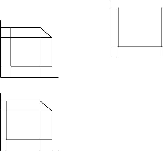
2. Environmental
The environmental conditions for assuring the copy quality and the machine operations are as follows:
(1) Normal operating condition |
(4) Supply storage condition |
|
Temperature: 20 - 25°C |
Humidity (RH) |
|
Humidity: 65 ± 5%RH |
90% |
|
|
|
|
(2) Acceptable operating condition
Humidity (RH) |
|
|
85% |
|
|
60% |
|
|
20% |
|
|
10˚C |
30˚C |
35˚C |
20%
–5˚C |
45˚C |
(3) Optical condition
Humidity (RH) |
|
|
90% |
|
|
60% |
|
|
15% |
|
|
–25˚C |
30˚C |
40˚C |
AL-1457 CONSUMABLE PARTS 3 - 1
3.Production control number (lot No.) identification
<Developing cartridge>
 Production month
Production day
Destination code
(Dealer, distributor, OEM, etc.) Production place
(SOCC: Fixed to B.) End digit of year Version No.
* Destination
Division |
|
No. |
|
|
|
|
|
EX Destination |
|
A same pack |
G |
|
|
|
|
|
|
B same pack |
H |
|
|
|
|
Option Destination |
|
A |
P |
|
|
|
|
|
|
B |
Q |
|
|
|
|
<Drum cartridge>
The label on the drum cartridge shows the date of production. (SOCC production)
 Production month
Production day
Destination code
(Dealer, distributor, OEM, etc.) Production place
(SOCC: Fixed to B.) End digit of year Version No.
<JAPAN production>
Ver.A 9 |
1 |
1 0001 X |
Production month
(1 - 9 = Jan. - Sep. 0 = Oct. X = Nov. Y = Dec.) Serial number of month
Fixed to 1.
Pack division
(See table below) End digit of year Version No.
Division |
No. |
|
|
Ex production |
1 |
|
|
Option |
2 |
|
|
Same pack |
3 |
|
|
Production control
label attachment position
Production control
label attachment position(*1)
*1 The production control label is not attached to the cartridge of a China product.
AL-1457 CONSUMABLE PARTS 3 - 2

[4] EXTERNAL VIEWS AND INTERNAL STRUCTURES
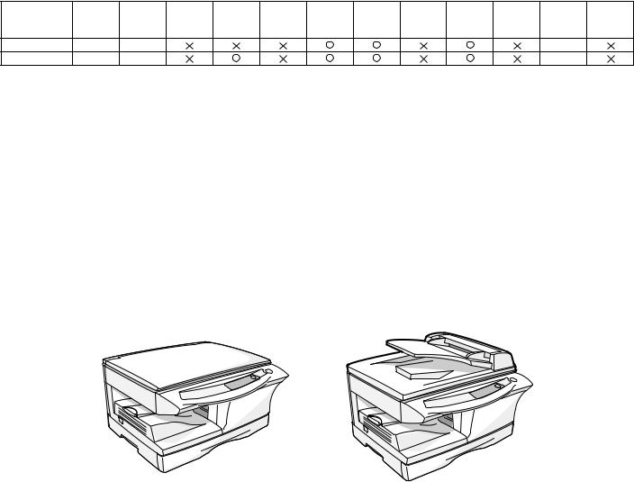
1. Appearance
SPF (AL-1457) |
(AL-1217) |
11 |
13 |
|
12 |
10 |
|
9 |
|
1 |
|
|
|
2 |
5 |
|
|
|
|
14 |
|
|
6 |
|
|
3 |
|
15 |
|
4 |
7 |
|
16 |
|
|
17 |
|
|
|
8 |
|
|
|
18 |
|
|
|
|
Single bypass
7
1 |
Original table |
2 |
Operation panel |
3 |
|
Front cover |
4 |
Paper tray |
5 |
Side cover |
6 |
Side cover open button |
|
7 |
Bypass paper guides |
8 |
Multi-bypass tray |
9 |
|
Document feeder tray |
10 |
SPF exit area |
11 |
Original guides |
12 |
Feeding roller cover |
|
13 |
Original cover |
14 |
Paper output tray |
15 |
Paper output tray extension |
|
16 |
Power switch |
17 |
Handle |
18 |
Power cord socket |
|
2. |
Internal |
|
|
|
|
|
|
|
2 |
|
3 |
|
|
|
|
|
|
|
|
|
4
5 |
|
|
1 |
|
|
6 |
|
|
|
|
|
7 |
1 |
Front cover |
2 |
TD cartridge |
3 |
Drum cartridge |
4 |
Side cover |
5 |
Fusing unit release lever |
6 |
Transfer charger |
7 |
Charger cleaner |
|
|
|
|
AL-1457 EXTERNAL VIEWS AND INTERNAL STRUCTURES 4 - 1
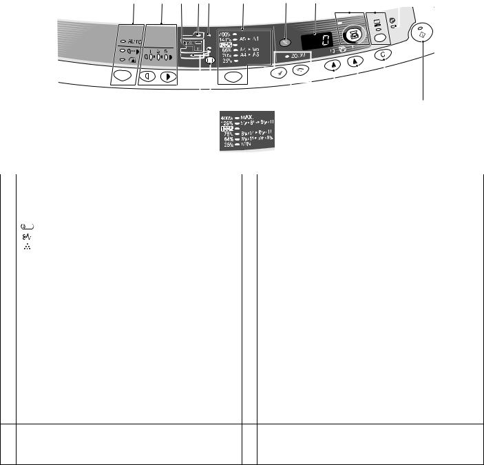
3. Operation panel
1 |
2 |
3 |
4 |
5 |
6 |
|
7 |
|
8 |
9 |
10 |
11 |
||||||||
|
|
|
|
|
|
|
|
|
|
|
|
|
|
|
|
|
|
|
|
|
|
|
|
|
|
|
|
|
|
|
|
|
|
|
|
|
|
|
|
|
|
|
|
|
|
|
|
|
|
|
|
|
|
|
|
|
|
|
|
|
|
|
|
|
|
|
|
|
|
|
|
|
|
|
|
|
|
|
|
|
|
|
|
|
|
|
|
|
|
|
|
|
|
|
|
|
|
|
|
|
|
|
|
|
|
|
|
|
|
|
|
|
|
|
|
|
|
|
|
|
|
|
|
|
|
12 13 14 15 16 17
|
Inch system |
|
|
|
|
6 |
|
|
|
|
|
||
|
(AL-1457) |
|
|
|
|
|
|
|
|
|
|
|
|
|
|
|
|
|||
1 |
Exposure mode selector key and indicators |
2 |
Light and dark keys and exposure indicators |
|||
|
Use to sequentially select the exposure modes: AUTO, MANUAL or |
|
Use to adjust the MANUAL or PHOTO exposure level. |
|||
|
PHOTO. Selected mode is shown by a lit indicator. |
|
Selected exposure level is shown by a lit indicator. |
|||
|
|
|
|
Use to start and terminate user program setting. |
||
3 |
Alarm indicators |
4 |
SPF indicator (AL-1457) |
|||
|
Drum replacement required indicator *1 |
|
|
|
|
|
|
Misfeed indicator |
|
|
|
|
|
|
TD cartridge replacement required indicator *2 |
|
|
|
|
|
5 |
SPF misfeed indicator (AL-1457) |
6 |
Copy ratio selector key and copy ratio indicators |
|||
|
|
|
|
Use to sequentially select preset reduction/enlargement copy ratios. |
||
|
|
|
|
Selected copy ratio is shown by a lit indicator. |
||
7 |
Copy ratio display (%) key |
8 |
Display |
|||
|
|
|
|
Displays the specified copy quantity, zoom copy ratio, user program |
||
|
|
|
|
code, and error code. |
||
9 |
SCANNER key and indicator *3, *4 |
10 |
ONLINE key / indicator |
|||
|
|
|
|
Lights up when the machine is used as a printer and scanner. *3 |
||
11 |
Power save indicator |
12 |
Paper feed location indicators |
|||
|
Lights up when the copier is in a power save mode. |
|
Light up to show the selected paper feed station. |
|||
13 |
Tray select key (AL-1457) |
14 |
Zoom keys / indicator |
|||
|
Use to select a paper feed station (paper tray or bypass tray). |
|
Use to select any reduction or enlargement copy ratio from 25% to |
|||
|
|
|
|
400% in 1% increments. |
||
15 |
Copy quantity keys |
16 |
Clear key |
|||
|
• Use to select the desired copy quantity (1 to 99). |
|
• Press to clear the display, or press during a copy run to terminate |
|||
|
• Use to make user program entries. |
|
copying. |
|||
|
|
|
|
• Press and hold down during standby to display the total number |
||
|
|
|
|
of copies made to date. |
||
17Print key and ready indicator
•Copying is possible when the indicator is on.
•Use to set a user program.
•Press to start copying
*1. Photoreceptor Cartridge Replacement indicator |
*2. Toner Developer Cartridge Replacement |
After making 17,000 copies, the indicator will be “ON”, and after 1,000 copier more are made, the indicator starts blinking and machine will hard-stop (after current job) until a new cartridge is installed. End life of photoreceptor cartridge displays 3-digits x 2- line (total 6-digits) by pressing CLEAR key for five seconds in user simulation.
When toner density is lower than a specified level, the TONER DEVELOPER CARTRIDGE REPLACEMENT indicator lights up to warn the user. If the Toner Developer Cartridge is not replaced in that time, the Ready Lamp changes to blinking and then start to supply the toner after around 10 copies. (Cartridge replacement lamp continues to light.) If toner density is not back to specific level after two minutes, the READY indicator goes out and Toner Developer indicator starts blinking, and the copier stops.
AL-1457 EXTERNAL VIEWS AND INTERNAL STRUCTURES 4 - 2

*3. Indicators on the operation panel
The ON LINE indicator and the start (  ) indicator indicate the state of the printer or scanner.
Start indicator
On: |
Indicates the unit is ready for copying or scanning is |
|
being performed. |
Blinking: Indicates that an interrupt print job is in progress, or that the unit is initializing (the cover has been opened and closed or the power turned off and on).
Off: |
Indicates copying or scanning is being performed or the |
|
unit is in the auto power shut-off mode. |
SCANNER indicator
ON LINE indicator
 Start indicator
 Power save indicator
ON LINE indicator
The ON LINE key is pressed and on line and off line are changed.
On: |
Indicates the unit is ready for printing or scanning is |
|
being performed. (On line) |
Blinking: Printing or data is being received from a computer.
Off: |
Copying is being performed. (Off line) |
|
Power save indicator |
|
|
On: |
Indicates the unit is in a power save mode. |
|
Scanner indicator |
|
|
On: |
The SCANNER ( |
) key has been pressed and the unit |
|
is in scanner mode. |
|
Blinking: A scan job is being executed from the computer, or scan data is stored in the unit's memory.
Off: |
The unit is in the copy mode. |
*4. Using the SCANNER key to begin scanning
This scanning method can only be used if the Button Manager has been installed using the installer. To scan using this method, you must first complete the settings in Button Manager in your computer. For more information on Button Manager, see the online manual or the help file for Button Manager.
Note:
•Scanning is not possible during a copy job.
•If the unit is used to begin a scan job during a print job using the parallel interface connection or the USB interface connection, the scan job will be stored and scanning will begin when the print job is completed.
•When scanning an original that has been placed in the SPF/ RSPF, only one original can be placed unless you are using Sharpdesk.
1)Press the SCANNER ( ) key. The unit enters scan mode.
2)Place the original you wish to scan on the original table/SPF/ RSPF.
For the procedure for placing the original, see "ORIGINAL PLACEMENT".
3)Press the right copy quantity key to display the number of the application that you wish to use for scanning.
The application numbers are initially as follows.
The application numbers are initially as follows.
Application |
Application launched |
|
number |
||
|
||
SC1 |
Sharpdesk (if installed) |
|
SC2 |
E-mail (your standard e-mail program in the |
|
|
Windows OS you are using) |
|
SC3 |
Fax (if a fax program is installed) |
|
SC4 |
OCR (if an OCR program is installed) |
|
SC5 |
Microsoft Word (if installed) |
|
SC6 |
Any application set in Button Manager |
4)Press the start (  ) key.
The selected application launches and scanning begins.
AL-1457 EXTERNAL VIEWS AND INTERNAL STRUCTURES 4 - 3
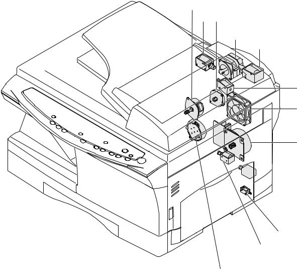
4. Motors and solenoids
9
12 2
8
11
10
4
1
 5
5
|
|
|
|
|
7 |
|
|
|
|
||
|
|
|
|
|
6 |
|
|
|
|
|
|
|
|
|
3 |
||
|
|
|
|
|
|
No. |
Part name |
Control signal |
|
|
Function / Operation |
1 |
Main motor |
MM |
Drives the copier. |
||
2 |
Scanner motor |
MRMT |
Drives the optical mirror base (scanner unit). |
||
3 |
Toner motor |
TM |
Supplies toner. |
||
4 |
Cooling fan motor |
VFM |
Cools the optical section. |
||
5 |
Resist roller solenoid |
RRS |
Resist roller rotation control solenoid |
||
6 |
Paper feed solenoid |
CPFS1 |
Cassette Paper feed solenoid 1 |
||
7 |
Multi paper feed solenoid |
MPFS |
Multi manual pages feed solenoid |
||
8 |
SPF motor |
SPFM |
Drives the single pass feeder |
||
9 |
Duplex motor |
DMT |
Devices the duplex paper transport section |
||
10 |
Original feed solenoid |
SPUS |
Original feed solenoid |
||
11 |
Original resist roller solenoid |
SRRC |
Original resist roller solenoid |
||
12 |
Original paper feed solenoid |
SPFS |
Original paper feed solenoid |
||
AL-1457 EXTERNAL VIEWS AND INTERNAL STRUCTURES 4 - 4

5. Sensors and switches
|
11 |
1 |
2 |
|
9
10
3
4
|
|
|
|
|
|
5 |
|
|
|
8 |
|
|
6 |
|
|
|
7 |
|||
|
|
|
|
|||
|
|
|
|
|
||
|
|
|
|
|
|
|
No. |
Name |
Signal |
Type |
|
Function |
Output |
1 |
Scanner unit home position |
MHPS |
Transmission sensor |
Scanner unit home position detection |
"H" at home position |
|
|
sensor |
|
|
|
|
|
2 |
POD sensor |
POD |
Transmission sensor |
Paper exit detection |
"H" at paper pass |
|
3 |
PPD2 sensor |
PPD2 |
Transmission sensor |
Paper transport detection 2 |
"L" at paper pass |
|
4 |
Cassette detection switch |
CED1 |
Micro-switch |
Cassette installation detection |
"L" at cassette insertion |
|
5 |
Manual feed detection |
MFD |
Transmission sensor |
Manual feed paper detection |
"L" at paper detection |
|
|
switch |
|
|
(single only) |
|
|
6 |
PPD1 sensor |
PPD1 |
Transmission sensor |
Paper transport detection 1 |
"L" at paper pass |
|
7 |
Door switch |
DSW |
Micro-switch |
Door open/close detection |
1 or 0V of 24V at door open |
|
|
|
|
|
(safety switch for 24V) |
|
|
8 |
Drum reset switch |
DRST |
Micro-switch |
New drum detection switch |
Instantaneously "L" at insertion of new |
|
|
|
|
|
|
|
drum |
9 |
SPF sensor |
SPID/ |
Transmission sensor |
Paper entry detection |
"L" at paper pass |
|
|
|
SD SW |
|
Cover open/close detection |
|
|
10 |
SPPD sensor |
SPPD |
Transmission sensor |
Paper transport detection |
"L" at paper pass |
|
11 |
SDOD sensor |
SDOD |
Transmission sensor |
SPF open/close detection Book |
"L" at paper pass |
|
|
|
|
|
sensor |
|
|
AL-1457 EXTERNAL VIEWS AND INTERNAL STRUCTURES 4 - 5
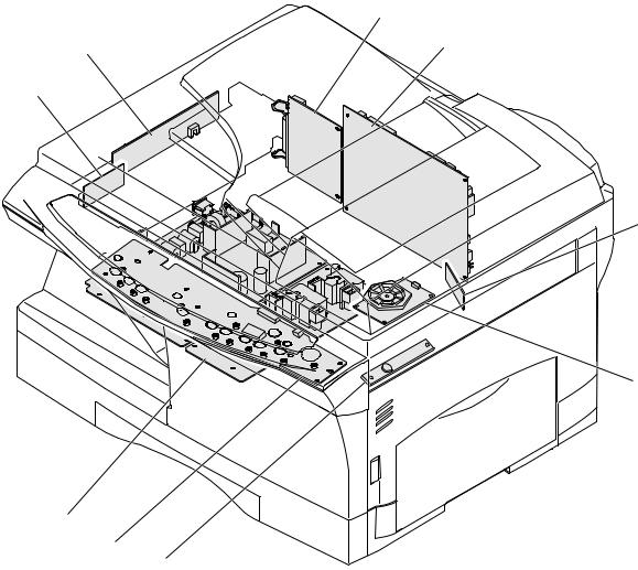
6. PWB unit
9
2
5
1
8
6
4
3
7
No. |
Name |
Function |
1 |
Exposure lamp invertor PWB |
Exposure lamp (CCFL) control |
2 |
Main PWB (MCU) |
Copier control |
3 |
Operation PWB |
Operation input/display |
4 |
Power PWB |
AC power input, DC voltage control, High voltage control |
5 |
CCD sensor PWB |
For image scanning |
6 |
LSU motor PWB |
For polygon motor drive |
7 |
TCS PWB |
For toner sensor control |
8 |
LSU PWB |
For laser control |
9 |
I/F PWB |
Scanner/GDI Printer control (parallel I/F, USB I/F) |
AL-1457 EXTERNAL VIEWS AND INTERNAL STRUCTURES 4 - 6

7. Cross sectional view
|
|
3 |
17 |
14 |
15 |
|
|
5 |
|
|
|
|
2 |
4 |
|
|
|
|
|
|
|
|
|
|
|
|
|
|
16 |
|
1 |
|
|
|
|
|
|
|
|
|
6 |
|
|
|
|
|
7 |
|
|
|
|
|
8 |
|
|
|
|
|
9 |
|
|
|
|
|
10 |
|
|
|
|
|
11 |
|
|
|
|
13 |
12 |
No. |
Part name |
|
|
Function and operation |
|
1 |
Scanner unit |
Illuminates the original with the copy lamp and passes the reflected light to the lens unit(CCD). |
|||
2 |
Exposure lamp |
Exposure lamp (CCFL) Illuminates original |
|
|
|
3 |
LSU (Laser unit) |
Converts the original image signal into laser beams and writes onto the drum. |
|||
4 |
Paper exit roller |
Roller for paper exit |
|
|
|
5 |
Main charger |
Provides negative charges evenly to the drum surface. |
|
||
6 |
Heat roller |
Fuses toner on the paper. (Teflon roller) |
|
|
|
7 |
Pressure roller |
Fuses toner on the paper. (Silicon rubber roller) |
|
||
8 |
Drum |
Forms images. |
|
|
|
9 |
Transfer unit |
Transfers images onto the drum. |
|
|
|
10 |
Pickup roller |
Picks up the manual feed paper. (In multi feed only) |
|
||
11 |
Manual paper feed tray |
Tray for manual feed paper |
|
|
|
12 |
Manual paper feed roller |
Transport the paper from the manual paper feed port. |
|
||
13 |
PS roller unit |
Takes synchronization between the lead edge and the rear edge of the paper. |
|||
14 |
Pickup roller |
Picks up documents. |
|
|
|
15 |
Separation roller |
Separates documents to feed properly. |
|
|
|
16 |
PS roller |
Feeds documents to the scanning section. |
|
|
|
17 |
Paper exit roller |
Discharges documents. |
|
|
|
AL-1457 EXTERNAL VIEWS AND INTERNAL STRUCTURES 4 - 7

[5] UNPACKING AND INSTALLATION
1. Copier installation
Improper installation may damage the copier. Please note the following during initial installation and whenever the copier is moved.
Caution: If the copier is moved from a cool place to a warm place, condensation may form inside the copier. Operation in this condition will cause poor copy quality and malfunctions.
Leave the copier at room temperature for at least 2 hours before use.
Do not install your copier in areas that are:
• damp, humid, or very dusty
• exposed to direct sunlight
• poorly ventilated
•subject to extreme temperature or humidity changes, e.g., near an air conditioner or heater.
The copier should be installed near an accessible power outlet for easy connection.
Be sure to connect the power cord only to a power outlet that meets the specified voltage and current requirements.
Also make certain the outlet is properly grounded.
Be sure to allow the required space around the machine for servicing and proper ventilation.
8" (20cm) |
8"(20cm) |
4" |
4" |
(10cm) |
(10cm) |
2. Cautions on handling
Be careful in handling the copier as follows to maintain the performance of this copier.
Do not drop the copier, subject it to shock or strike it against any object.
Do not expose the drum cartridge to direct sunlight.
Doing so will damage the surface (green portion) of the drum cartridge, causing poor print quality.
Store spare supplies such as drum cartridges and TD cartridges in a dark place without removing from the package before use.
If they are exposed to direct sunlight, poor print quality may result.
Do not touch the surface (green portion) of the drum cartridge.
Doing so will damage the surface of the cartridge, causing poor print quality.
3.Checking packed components and accessories
Open the carton and check if the following components and accessories are included.
Operation manual |
Drum cartridge |
|
|
|
(installed in unit) |
Power cord
TD cartridge
AL-1457 UNPACKING AND INSTALLATION 5 - 1

4. Unpacking |
6. Installing the TD cartridge |
Be sure to hold the handles on both sides of the copier to unpack the copier and carry it to the installation location.
5. Removing protective packing materials
1)Remove pieces of tape and protective cover. Then open the original cover and remove protective materials (a) and (b).
The TD cartridge replacement required (  ) indicator will light up when toner is needed. If copying is continued while the
  indicator is lit, copies will gradually become lighter until the copier stops and the indicator begins blinking. Replace the old TD cartridge by following the procedure given below.
Note:
•After the copier stops, it may be possible to make a few more copies by taking the TD cartridge out of the copier, shaking it horizontally, then reinstalling it. If copying is not possible after this operation, replace the TD cartridge.
•During long copy run of a dark original, the ready (  ) indicator may blink, the
  indicator may light up, and the copier may stop, even though toner cartridge is not empty. The copier will feed toner up to 2
minutes and then the ready (  ) indicator will light up. Press the print (
  ) key to restart copying.
1)Ensure that the bypass tray is open and then open the side cover by pressing the open button on the side cover.
2) Remove the CAUTION tape from the front cover and remove the two protective pins from the fusing unit by pulling the strings upward one at a time.
AL-1217 |
AL-1457 |
Protective pins
CAUTION tape
AL-1217 |
AL-1457 |
3) Push gently on both sides of the front cover to open the cover.
2) Release the scan head locking switch.
Grasp here and turn in the direction of the arrow.
Lock |
Unlock |
4) Remove the TD cartridge from the bag. Remove the protective paper. Hold the cartridge on both sides and shake it horizontally four or five times.
4 or 5 times
AL-1457 UNPACKING AND INSTALLATION 5 - 2
5)Hold the tab of the protective cover and pull the tab to remove the cover.
6) Gently insert the TD cartridge until it locks in place.
Paper |
Paper |
guide (B) |
guide (A) |
5)Fan the copy paper and insert it into the tray. Make sure the edges go under the corner hooks.
Note: Do not load paper above the maximum height line ( 
 ). Exceeding the line will cause a paper misfeed.
7)Close the front cover and then the side cover by pressing the
round projections near the side cover open button. The  indicator will go out and the ready (
  ) indicator will light up.
Note: When closing the covers, be sure to close the front cover securely and then close the side cover. If the covers are closed in the wrong order, the covers may be damaged.
6) Gently push the paper tray back into the copier.
Note: After loading copy paper, to cancel the blinking "H" without restarting copying, press the clear (  ) key. The "P" in the display will go out and the ready (
  ) indicator will light up.
7. Loading copy paper
Note: This copier is equipped with two paper trays. Load copy paper into the two paper trays.
1)Raise the handle of the paper tray and pull the paper tray out until it stops.
2)Remove the pressure plate lock. Rotate the pressure plate lock in the direction of the arrow to remove it while pressing down the pressure plate of the paper tray.
3)Store the pressure plate lock that was removed in step 2 and the screw that was removed when unpacking the machine in the front of the paper tray. To store the pressure plate lock, rotate the lock to fix it on the relevant location.
4)Adjust the paper guides on the paper tray to the copy paper width and length.
Squeeze the lever of paper guide (A) and slide the guide to match with the width of the paper.
Move paper guide (B) to the appropriate slot as marked on the tray.
8. Power to copier
1)Ensure that the power switch of the copier is in the OFF position. Insert the attached power cord into the power cord socket at the rear of the copier.
2)Plug the other end of the power cord into the nearest outlet.
9.Software for the SHARP personal MFP series
The supplied CD-ROM includes software for this unit.
MFP driver
Scanner driver
Permits you to operate scanning function of this unit with TWAIN-com- pliant and WIA-compliant application.
Printer driver
Enables you to use the printer function of this unit with your computer.
Print Status Window
The print state and information on current printing are displayed on the status monitor window.
Sharpdesk
An integrated software environment that makes it easy to manage document and image files and launch applications.
Button Manager
Button Manager enabling the SCANNER key located on the unit.
AL-1457 UNPACKING AND INSTALLATION 5 - 3

(Hardware and software requirements)
Check the following hardware and software requirements in order to install the software.
Computer type |
IBM PC/AT or compatible computer equipped with |
|
a USB1.1*1 or bi-directional parallel interface |
|
(IEEE 1284) |
Operating |
Windows 95, Windows 98, Windows Me, Windows |
system*2 |
NT Workstation 4.0 (ServicePack 5 or later)*3, |
|
Windows 2000 Professional, Windows XP |
|
Professional*3, Windows XP Home Edition*3 |
Display |
800 x 600dots (SVGA) display with 256 colors (or |
|
better) |
Hard disk free |
150MB or more |
space |
|
Other |
An environment on which any of the operating |
requirement for |
systems listed above can fully operate |
hardware |
|
*1: Compatible with Windows 98, Windows Me, Windows 2000 Professional, Windows XP Professional or Windows XP Home Edition preinstalled model with USB interface equipped as standard.
*2: Printing is unavailable in MS-DOS mode.
*3: The administrator's authorization is required to install this software using this installer.
(Before installation)
The following table shows the drivers and software that can be installed for each version of Windows and interface connection method.
|
MFP Driver |
|
|
|
|
Printer |
|
Button |
|
|
driver/ |
Scanner |
Sharpdesk |
|
|
Manager |
|||
|
Print Status |
driver |
|
|
|
Window |
|
|
|
Users of Windows |
|
|
|
|
98/Me/2000/XP |
|
|
|
|
who will use the |
|
Available |
Available |
Available |
USB interface |
|
|
|
|
connection |
|
|
|
|
Users of Windows |
Available*1 |
|
|
|
98/Me/2000/XP |
|
|
|
|
|
|
|
|
|
who will use the |
|
Not |
Not |
|
parallel interface |
|
Available*2 |
||
|
Available |
Available |
||
connection |
|
|
||
|
|
|
|
|
Windows 95/NT 4.0 |
|
|
|
|
users |
|
|
|
|
*1: When the unit is connected through the parallel port, the Print Status Window can only be used when the parallel port is set to ECP mode. To set the parallel port mode, refer to your computer manual or ask the manufacturer of your computer.
*2: Sharpdesk can be installed when using a parallel interface connection, however, the unit's scanner function cannot be used.
•If you are using some of your computer's memory as a RAM drive, the printer driver may not be allocated the correct amount of memory. In such a case, reduce the size of your RAM disk, or do not use the RAM disk. Please refer to your Windows documentation for further information.
•Is there another GDI printer driver or a Windows Printing System printer driver already installed? If installed, change the printer port setting. For the change of the printer port setting, see "USING OTHER INSTALLED DRIVERS".
(Flow of installation)
Refer to the following table and then begin installation
Operating |
Interface |
Reference pages for how to install |
|
system |
|||
|
|
||
Windows XP |
USB/ |
Installing onto Windows XP (USB/parallel |
|
Parallel |
interface) |
||
|
|||
|
USB |
Installing onto Windows 98/Me/2000 (USB |
|
|
interface) |
||
Windows 98 |
|
||
Parallel |
Installing onto Windows 95/98/Me/NT4.0/ |
||
|
|||
|
2000 (Parallel interface) |
||
|
USB |
Installing onto Windows 98/Me/2000 (USB |
|
|
interface) |
||
Windows Me |
|
||
Parallel |
Installing onto Windows 95/98/Me/NT4.0/ |
||
|
|||
|
2000 (Parallel interface) |
||
|
USB |
Installing onto Windows 98/Me/2000 (USB |
|
Windows |
interface) |
||
|
|||
2000 |
Parallel |
Installing onto Windows 95/98/Me/NT4.0/ |
|
|
|
2000 (Parallel interface) |
|
Windows 95/ |
Parallel |
Installing onto Windows 95/98/Me/NT4.0/ |
|
NT 4.0 |
|
2000 (Parallel interface) |
(Installing the software)
The following term is used in this section.
MFP
Means the unit as a printer and scanner.
•For this description, it is assumed that the mouse is configured for right hand operation.
•To print or scan, the MFP must be in the online state.
•The scanner feature only works when using a USB interface cable.
•If any error message appears, solve the problem following the instructions on the screen. After your problem is solved, the installing procedure will be continued. Depending on your problem, you may have to exit the installer. In this case, click the "Cancel" button to exit the installer. After solving your problem, reinstall the software from the beginning.
A. Windows XP (USB/parallel interface)
Before starting the installation, make sure the USB or parallel interface cable is not connected to the MFP.
1)Insert the supplied CD-ROM into your CD-ROM drive.
2)Click the "start" button, click "My Computer", and then double-click the CD-ROM icon.
•When any of "Found New Hardware Wizard" messages appear during the software installation, be sure to click the "Cancel" button.
3)Double-click the "Setup" icon.
If the language selection screen appears after you double click the "Setup" icon, select the language you wish to use and click the "Next" button. (Normally, the correct language is selected automatically.)
4)Select the software packages to be installed, and then click the "Next" button.
The software packages with checkmark on the list on the screen will be installed.
Click the "Display README" button to show the information on the selected package.
AL-1457 UNPACKING AND INSTALLATION 5 - 4
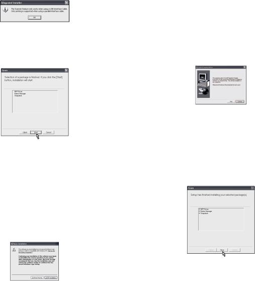
•If you are using the parallel interface connection, do not select the Button Manager checkbox because this feature is not supported with the parallel interface.
•If the following screen appears, click the "OK" button. Review the contents in "BEFORE INSTALLATION", and then select only appropriate the software packages to be installed.
5)Review the software packages to be installed on the screen, and then click the "Start" button.
The software packages to be installed will be displayed on the screen. If inappropriate packages are displayed, click the "Back" button to select appropriate packages again.
6)Copying files for MFP driver installation and parallel interface setup (This step will start if it was selected in step 4).
1.After confirming the message in the "Welcome" window, click the "Next" button.
2.A dialog box appears asking you to verify that the USB or parallel interface cable is not connected to the MFP. Make sure that the interface cable is not connected and click the "Next" button.
3.Click the "Next" button in the dialog box to install the MFP driver or Cancel to quit the installation.
The setup program will start to copy the files.
If the following screen appears while the files are being copied (the message may appear more than once), click "Continue Anyway".
4.When the "The MFP driver installation is complete." dialog box appears, click the "OK" button.
The Button Manager installer will start.
7)Begin installation of the Button Manager (This step will start if it was selected in step 4).
1.After confirming the message in the "Welcome" window, click the "Next" button.
2.Read the message in the "Please read the following information." window, and then click the "Next" button.
3.When a message appears that lets you specify the location for the software to be installed, click the "Next" button.
4.If the program displays, "Do you want the Button Manager added to Windows Startup?", check "Yes" and click the "OK" button.
The setup program will start to copy the files.
5.Click the "Finish" button when the message informs you that setup is successful.
The Sharpdesk installer will start.
8)Begin installation of the Sharpdesk (This step will start if it was selected in step 4).
1.After confirming the message in the "Welcome to Sharpdesk installation" window, click the "Next" button.
2.Read the message in the "Information" window, and then click the "Next" button.
3.When the "Choose Destination Location" window appears, click the "Next" button.
4.When the "Select Program Folder" window appears, click the "Next" button.
The setup program will start to copy the files.
If the dialog box asking "If you have TIFF files saved using Photo-Shop or Imaging for Windows you should hit Skip" appears. Answer the question to continue the Sharpdesk installation.
5.Click the "Finish" button when the message informs you that Setup is complete.
9)Click the "Close" button when the message informs you that "Setup has finished". When the "Now connect the MFP interface cable to the PC" dialog box appears, click the "OK" button.
• After the installation, a message to restart your computer may be displayed. In this case, click the "Yes" button to restart your computer.
• For parallel interface connection ensure that your computer and MFP are turned off before connecting the cable.
10)Connect the USB interface cable or parallel interface cable (see page 5-8).
Windows will detect the MFP and the Plug and Play screen will appear. If you are using Windows XP with the parallel interface, go to step 12.
11)Begin installation of the scanner driver.
1."SHARP AL-xxxx" (where xxxx is the model name of your MFP) will appear in the "Found New Hardware Wizard" dialog box. Select "Install the software automatically (Recommended)" and click the "Next" button.
2.The "Install hardware" dialog box will appear. Click the "Continue Anyway" button.
3.When installation of the driver is completed, click the "Finish" button to finish the scanner driver installation.
12)Begin installation of the printer driver.
1."SHARP AL-xxxx" (where xxxx is the model name of your MFP) will appear in the "Found New Hardware Wizard" dialog box. Select "Install the software automatically (Recommended)" and click the "Next" button.
2.The "Hardware Installation" dialog box will appear. Click the "Continue Anyway" button.
3.When installation of the driver is completed, click the "Finish" button to finish the printer driver installation.
You have completed the installation of all the software.
AL-1457 UNPACKING AND INSTALLATION 5 - 5

B. Windows 98/Me/2000 (USB interface)
Before starting the installation, make sure the USB interface cable is not connected to the MFP.
1)Insert the supplied CD-ROM into your CD-ROM drive.
2)Double-click "My Computer", and then double-click the CD-ROM icon.
•When any of "Hardware Found", or "Found New Hardware Wizard" messages appear during the software installation, be sure to click the "Cancel" button.
3)Double-click the "Setup" icon.
•If the language selection screen appears after you double click the "Setup" icon, select the language you wish to use and click the "Next" button. (Normally, the correct language is selected automatically.)
4)Select the software packages to be installed, and then click the "Next" button.
The software packages with checkmark on the list on the screen will be installed. Click the "Display README" button to show the information on the selected package.
•If the following screen appears, click the "OK" button. Review the contents in "BEFORE INSTALLATION", and then select the appropriate driver software packages to be installed.
5)Review the software packages to be installed on the screen, and then click the "Start" button.
The software packages to be installed will be displayed on the screen. If inappropriate packages are displayed, click the "Back" button to select appropriate packages again.
6)Copying files for MFP driver installation.
1.After confirming the message in the "Welcome" window, click the "Next" button.
2.A dialog box appears asking you to verify that the interface cable is not connected to the MFP. Make sure that the interface cable is not connected and click the "Next" button.
3.Click the "Next" button in the dialog box showing the files to be copied for installation of the MFP driver.
The setup program will start to copy the files.
In Windows 2000, if the following screen appears while the files are being copied (the message may appear more than once), click "Yes" in Windows 2000.
4.The following screen appears when all of the files for the USB interface connection have been copied. If you are not using a parallel interface cable for connection to the MFP, please click the "No" button.
5.When the "The MFP driver installation is complete." dialog box appears, click the "OK" button.
The Button Manager installer will start.
7)Begin installation of the Button Manager (This step will start if it was selected in step 4).
1.After confirming the message in the "Welcome" window, click the "Next" button.
2.Read the message in the "Please read the following information." window, and then click the "Next" button.
3.When a message appears that lets you specify the location for the software to be installed, click the "Next" button.
4.If the program displays, "Do you want to add Button Manager to Startup program?", check "Yes" and click the "OK" button.
The setup program will start to copy the files.
5.Click the "Finish" button when the message to inform you of the completion of the installation appears.
The Sharpdesk installer will start.
8)Begin installation of the Sharpdesk (This step will start if it was selected in step 4).
1.After confirming the message in the "Welcome to Sharpdesk installation" window, click the "Next" button.
2.Read the message in the "Information" window, and then click the "Next" button.
3.When the "Choose Destination Location" window appears, click the "Next" button.
4.When the "Select Program Folder" window appears, click the "Next" button.
The setup program will start to copy the files.
If the dialog box asking "If you have TIFF files saved using Photo-Shop or Imaging for Windows you should hit Skip" appears. Answer the question to continue the Sharpdesk installation.
5.Click the "Finish" button when the message to inform you of the completion of the installation appears.
AL-1457 UNPACKING AND INSTALLATION 5 - 6
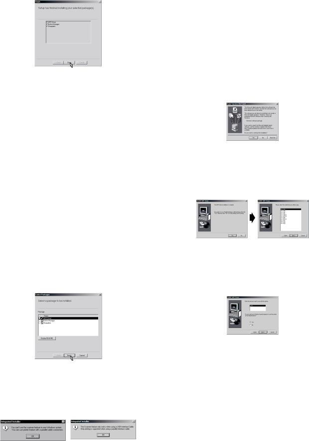
9)Click the "Close" button when the message to inform you of the completion of the installation appears. When the "Now connect the MFP interface cable to the PC. This will finalize the drivers installation and settings." dialog box appears, click the "OK" button.
•After the installation, a message to restart your computer may be displayed. In this case, click the "Yes" button to restart your computer.
10)Connect the USB interface cable (see page 5-8).
Windows will detect the MFP and the Plug and Play screen will appear.
11)Follow the instructions in the Plug and Play screen that appears in your version of Windows to begin the installation.
You have completed the installation of the software.
C. Windows 95/98/Me/NT4.0/2000 (Parallel interface)
Before starting the installation, make sure the USB or parallel interface cable is not connected to the MFP.
1)Insert the supplied CD-ROM into your CD-ROM drive.
2)Double-click "My Computer", and then double-click the CD-ROM icon.
•When any of "Hardware Found", or "Found New Hardware Wizard" messages appear during the software installation, be sure to click the "Cancel" button.
3)Double-click the "Setup" icon.
•If the language selection screen appears after you double click the "Setup" icon, select the language you wish to use and click the "Next" button. (Normally, the correct language is selected automatically.)
4)Select the software packages to be installed, and then click the "Next" button.
The software packages with checkmark on the list on the screen will be installed.
Click the "Display README" button to show the information on the selected package.
•In Windows 95/NT 4.0, "Button Manager" does not appear. In Windows 98/Me/2000, do not select the "Button Manager" checkbox. because this is not supported when using the parallel interface.
5)The next screen appears. Make sure that the parallel interface cable is not connected, and click "OK".
Windows 95/NT 4.0 |
Windows 98/Me/2000 |
6)Check the contents of the package on the screen, and then click the "Start" button.
The software packages to be installed will be displayed on the screen. If inappropriate packages are displayed, click the "Back" button to select only appropriate software packages.
7)Copying files for MFP driver installation and parallel interface setup (This step will start if it was selected in step 4).
1.After confirming the message in the "Welcome" window, click the "Next" button.
2.A dialog box appears asking you to verify that the USB or parallel interface cable is not connected to the MFP. Make sure that the interface cable is not connected and click the "Next" button.
3.Click the "Next" button in the dialog box to install the MFP driver or Cancel to quit the installation.
The setup program will start to copy the files.
In Windows 2000, if the following screen appears while the files are being copied (the message may appear more than once), click "Yes" in Windows 2000.
4.The following screen appears. Click the "Yes" button, and then the Model screen will appear. Select the model number that is the same as the model name of your MFP and click the "Next" button.
Be sure to select the displayed model number that is the same as the MFP's model name. If they are not the same, the driver will not be installed correctly.
5.Establish the printer settings and click the "Next" button.
Select "LPT1" for the port to be used. If "LPT1" does not appear, it is likely that another printer or peripheral device is using "LPT1". Check your other printers and peripheral devices, and change the port setting as needed so no device is using "LPT1". If you wish the MFP to be your default printer, select "Yes". If not, select "No".
6.When the "Setup has completed gathering all necessary installation information" dialog box appears, click the "Yes" button. The parallel interface driver is installed.
7.When the "The MFP driver installation is complete." dialog box appears, click the "OK" button.
The Sharpdesk installer will start.
8)Begin installation of the Sharpdesk (This step will start if it was selected in step 4).
1.After confirming the message in the "Welcome to Sharpdesk installation" window, click the "Next" button.
2.Read the message in the "Information" window, and then click the "Next" button.
3.When the "Choose Destination Location" window appears, click the "Next" button.
AL-1457 UNPACKING AND INSTALLATION 5 - 7

4.When the "Select Program Folder" window appears, click the "Next" button.
The setup program will start to copy the files.
If the dialog box asking "If you have TIFF files saved using Photo-Shop or Imaging for Windows you should hit Skip" appears. Answer the question to continue the Sharpdesk installation.
5.Click the "Finish" button when the message to inform you of the completion of the installation appears.
9)Click the "Close" button when the message to inform you of the completion of the installation appears.
•After the installation, a message to restart your computer may be displayed. In this case, click the "Yes" button to restart your computer.
10)Connect the parallel interface cable.
You have completed the installation of all the software.
•For parallel interface connection ensure that your computer and MFP are turned off before connecting the cable (see page 5-8).
10. Connecting the interface cable
This unit includes both USB and parallel interface connectors. Interface cables for connecting the unit to your computer are not included with this unit.
Caution:
•If you intend to use the unit as a scanner, it must be connected to your computer with a USB interface cable. The scanner function cannot be used if the unit is connected with a parallel cable.
•USB is available with a PC/AT compatible computer that was originally equipped with USB and had Windows 98, Windows Me, Windows 2000 Professional, Windows XP Professional or Windows XP Home Edition preinstalled.
•Do not connect the interface cable before installing the MFP driver. The interface cable should be connected during installa-tion of the MFP driver.
Connecting the USB interface cable
1)Obtain a shielded USB interface cable.
2)Insert the cable into the USB interface connector located on the rear of the unit.
3)Insert the other end of the cable into the interface connector of your computer, or the USB hub connected to your computer.
Connecting the parallel interface cable
1)Obtain an IEEE1284 shielded parallel interface cable.
2)Ensure that your computer and unit are turned off.
3)Insert the cable into the parallel interface connector located on the rear of the unit, and fasten with clasps.
4)Insert the other end of the cable into the interface connector of your computer.
11. Parallel interface
This printer uses a bi-directional parallel interface. Use the supplied interface cable.
Connector
36-pin ACON RBE42-36K1153 female connector or equivalent connector
Cable
Shielded type bi-directional parallel interface For best results, use a printer interface cable which is IEEE1284 compliant.
Pin configuration
The pin numbers and signal names are listed in the following table.
18 |
1 |
|
|
36 |
|
|
|
19 |
|
|
|||||
|
|
|
|
|
|
|
|
|
|
|
|
|
|
Pin |
|
|
|
Signal name |
Pin |
|
Signal name |
||||||
No. |
|
|
|
No. |
|
||||||||
|
|
|
|
|
|
|
|
|
|
|
|
||
|
|
|
|
|
|
|
|
|
|
||||
1 |
|
|
|
|
|
|
19 |
|
GND (STB RET) |
||||
|
STB |
||||||||||||
2 |
|
|
DATA1 |
20 |
|
GND (DATA1 RET) |
|||||||
|
|
|
|
|
|
|
|||||||
3 |
|
|
DATA2 |
21 |
|
GND (DATA2 RET) |
|||||||
|
|
|
|
|
|
|
|||||||
4 |
|
|
DATA3 |
22 |
|
GND (DATA3 RET) |
|||||||
|
|
|
|
|
|
|
|||||||
5 |
|
|
DATA4 |
23 |
|
GND (DATA4 RET) |
|||||||
|
|
|
|
|
|
|
|||||||
6 |
|
|
DATA5 |
24 |
|
GND (DATA5 RET) |
|||||||
|
|
|
|
|
|
|
|||||||
7 |
|
|
DATA6 |
25 |
|
GND (DATA6 RET) |
|||||||
|
|
|
|
|
|
|
|||||||
8 |
|
|
DATA7 |
26 |
|
GND (DATA7 RET) |
|||||||
|
|
|
|
|
|
|
|||||||
9 |
|
|
DATA8 |
27 |
|
GND (DATA8 RET) |
|||||||
|
|
|
|
|
|
|
|
|
|
|
|
|
|
10 |
|
|
|
|
|
|
28 |
|
GND |
|
|
|
RET) |
ACKNLG |
(ACKNLG |
||||||||||||
11 |
|
|
BUSY |
29 |
|
GND (BUSY RET) |
|||||||
|
|
|
|
|
|
||||||||
12 |
|
PE (Paper End) |
30 |
|
GND (PE RET) |
||||||||
|
|
|
|
|
|
||||||||
13 |
|
SLTC |
31 |
|
INPRM |
||||||||
|
|
|
|
|
|
|
|
|
|||||
14 |
|
|
|
|
|
|
32 |
|
|
|
|
|
|
AUTO LF |
FAULT |
||||||||||||
15 |
|
|
(NC) |
33 |
|
(NC) |
|||||||
|
|
|
|
|
|
||||||||
16 |
|
|
GND (0 V) |
34 |
(NC) |
||||||||
|
|
|
|
|
|
|
|||||||
17 |
|
|
FG |
35 |
|
+5 V |
|||||||
|
|
|
|
|
|
|
|
||||||
18 |
|
|
+5 V |
36 |
|
|
|
|
|
||||
|
SLTC IN |
||||||||||||
AL-1457 UNPACKING AND INSTALLATION 5 - 8

12. USB interface
Connector
4-pin ACON UBR23-4K2200 Type-B connector
Cable
Shielded twisted pair cable
(2 m (6 feet) Max.: high-speed transmission equivalent)
Pin configuration
The pin numbers and signal names are listed in the following table.
Pin No. |
|
Signal name |
|||||
|
|
|
|
|
|
|
|
1 |
|
|
|
|
+5V |
||
|
|
|
|
|
|
|
|
2 |
|
|
|
|
-DATA |
||
|
|
|
|
|
|
|
|
3 |
|
|
|
|
+DATA |
||
|
|
|
|
|
|
|
|
4 |
|
|
|
|
GND |
||
|
|
|
|
|
|
|
|
2 |
|
|
1 |
||||
|
|
|
|
|
|
|
|
|
|
|
|
|
|
|
|
|
|
|
|
|
|
|
|
|
|
|
|
|
|
|
|
3 |
4 |
13. Moving
Moving instructions
When moving the unit, follow the procedure below.
Note: When moving this unit, be sure to remove the TD cartridge in advance.
1)Turn the power switch off and remove the power cord from the outlet.
2)Open the side cover and front cover, in that order. Remove the TD cartridge and close the front cover and side cover, in that order.
To open and close the side cover and front cover, and to remove the TD cartridge, see "TD CARTRIDGE REPLACEMENT".
3)Raise the handle of the paper tray and pull the paper tray out until it stops.
4)Push the center of the pressure plate down until it locks in place and lock the plate using the pressure plate lock which has been stored in the front of the paper tray.
5)Push the paper tray back into the unit.
6)Lock the scan head locking switch.
Note: When shipping the unit, the scan head locking switch must be locked to prevent shipping damage.
7)Close the multi-bypass tray and the paper output tray extension, and attach the packing materials and tape which were removed during installation of the unit. See "PREPARING THE UNIT FOR INSTALLATION".
8)Pack the unit into the carton. See "CHECKING PACKED COMPONENTS AND ACCESSORIES".
AL-1457 UNPACKING AND INSTALLATION 5 - 9
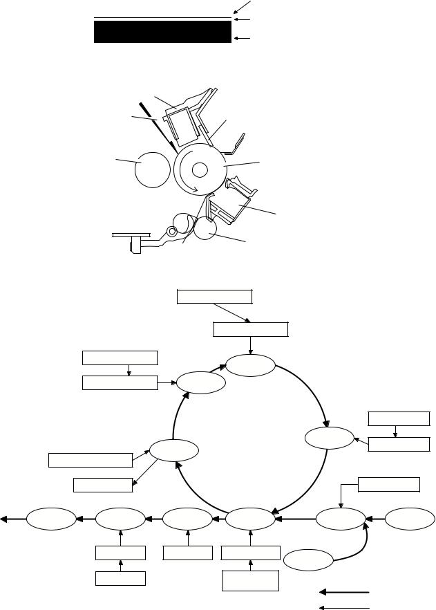
[6] COPY PROCESS
An OPC drum is used for the photoconductor.
(Structure of the OPC drum layers)
OPC layer
(20 microns thick)
Pigment layer (0.2 to 0.3 microns thick) Aluminum drum
1. Functional diagram
Main charger |
|
Laser beam |
Cleaning blade |
MG roller |
Drum |
|
|
|
|
|
Transfer unit |
|
|
|
|
|
|
Resist roller |
|
||
(Basic operation cycle) |
|
|
|
|
|
||
|
|
|
Semiconductor laser |
|
|
||
|
|
|
|
Focus correction lens |
|
||
|
|
Main high voltage unit |
|
Exposure |
|
|
|
|
|
|
|
|
|
||
|
|
Saw tooth |
Charge |
|
|
|
|
|
|
|
|
|
|
Toner |
|
|
|
|
|
Drum |
Developing |
Developer |
|
|
|
|
Cleaning |
|
|
||
|
|
|
|
|
|
||
|
Cleaning blade |
|
|
|
|
||
|
|
Waste toner box |
|
|
|
PS roller |
|
To face |
Paper release |
Fusing |
Separation |
Transfer |
Synchronization |
Manual feed |
|
down tray |
with drum |
||||||
|
|
|
|
|
|||
|
|
Heat roller |
Electrode |
Transfer charger |
Cassette |
|
|
|
|
|
|
|
|
||
|
|
|
|
|
paper feed |
|
|
|
|
Heater lamp |
|
Transfer high |
|
|
|
|
|
|
|
voltage unit |
|
Print process |
|
|
|
|
|
|
|
||
Paper transport route
AL-1457 COPY PROCESS 6 - 1
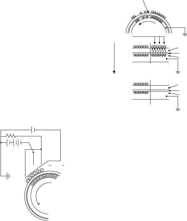
2. Outline of print process
This printer is a non-impact printer that uses a semiconductor laser and electrostatic print process. This printer uses an OPC (Organic Photo Conductor) for its photoconductive material.
First, voltage from the main corona unit charges the drum surface and a latent image is formed on the drum surface using a laser beam. This latent image forms a visible image on the drum surface when toner is applied. The toner image is then transferred onto the print paper by the transfer corona and fused on the print paper in the fusing section with a combination of heat and pressure.
Step-1: Charge Step-2: Exposure
* Latent image is formed on the drum. Step-3: Developing
Latent image formed on the drum is then changed into visible image with toner.
Step-4: Transfer
The visible image (toner image) on the drum is transferred onto the print paper.
Step-5: Cleaning
Residual toner on the drum surface is removed and collected by the cleaning blade.
Step-6: Optical discharge
Residual charge on the drum surface is removed, by semiconductor laser beam.
3. Actual print process
Step-1: DC charge
A uniform negative charge is applied over the OPC drum surface by the main charging unit. Stable potential is maintained by means of the Scorotron charger.
Positive charges are generated in the aluminum layer.
About
DC5.5KV
( 580V/ 390V)
Step-2: Exposure (laser beam, lens)
A Laser beam is generated from the semiconductor laser and controlled by the print pattern signal. The laser writes onto the OPC drum surface through the polygon mirrors and lens. The resistance of the OPC layer decreases for an area exposed by the laser beam (corresponding to the print pattern signal). The beam neutralizes the negative charge. An electrostatic latent image is formed on the drum surface.
Semiconductor laser
Exposure (semiconductor laser)
OPC layer Pigment layer
Aluminum drum
Drum surface charge after the exposure
OPC layer Pigment layer
Aluminum
layer
Non-image area Image area
AL-1457 COPY PROCESS 6 - 2

Step-3: Developing (DC bias)
A bias potential is applied to the MG roller in the two component magnetic brush developing method, and the toner is charged negative through friction with the carrier.
Non-image area of the drum surface charged with negative potential repel the toner, whereas the laser exposed portions where no negative charges exist, attract the toner. As a result, a visible image appears on the drum surface.
 :Carrier (Magnetized particle)
  :Toner (Charge negative by friction)
(N)(S) Permanent magnet (provided in three locations)
N
S
N
MG roller
DC
400V 8V
8V
Step-4: Transfer
The visible image on the drum surface is transferred onto the print paper by applying a positive charge from the transfer corona to the backside of the print paper.
About DC 5.2kV
Step-5: Separation
Since the print paper is charged positively by the transfer corona, it is discharged by the separation corona. The separation corona is connected to ground.
Step-6: Cleaning
Toner remaining on the drum is removed and collected by the cleaning blade. It is transported to the waste toner collecting section in the cleaning unit by the waste toner transport roller.
Toner is attracted over the shadowed area because of the developing bias.
AL-1457 COPY PROCESS 6 - 3
 Loading...