


 Loading...
|
AF-A07CE |
ROOM AIR CONDITIONER |
AF-A09CE |
INSTALLATION AND OPERATION |
AF-A12CE |
|
|
MANUAL |
|
КОМНАТНЫЙ КОНДИЦИОНЕР
РУКОВОДСТВО ПО УСТАНОВКЕ И ЭКСПЛУАТАЦИИ
CONTENTS |
PAGE |
PART NAMES AND DIMENSIONS ...... |
E-1 |
INSTALLATION INSTRUCTIONS ........ |
E-1 |
OPERATION INSTRUCTIONS ............. |
E-6 |
MODES OF OPERATION ..................... |
E-7 |
CLEANING AND MAINTENANCE ....... |
E-9 |
BEFORE CALLING FOR SERVlCE ..... |
E-10 |
ENGLISH
СОДЕРЖАНИЕ СТРАНИЦА
НАИМЕНОВАНИЕ ЧАСТЕЙ |
|
И РАЗМЕРЫ ........................................ |
R-1 |
ИНСТРУКЦИИ ПО УСТАНОВКЕ ....... |
R-1 |
ИНСТРУКЦИИ ПО ЭКСПЛУАТАЦИИ... |
R-6 |
РЕЖИМЫ РАБОТЫ ............................ |
R-7 |
ОЧИСТКА И УХОД.............................. |
R-9 |
ПРЕЖДЕ ЧЕМ ОБРАЩАТЬСЯ |
|
В СЛУЖБУ СЕРВИСНОГО |
|
ОБСЛУЖИВАНИЯ .............................. |
R-10 |
РУССКИЙ
This INSTALLATION AND OPERATION MANUAL explains the proper use of your new SHARP Air Conditioner. Read these instructions carefully before installing or operating your air conditioner. The INSTALLATION AND OPERATION MANUAL should be kept in a safe place for handy reference.
В настоящем РУКОВОДСТВЕ ПО УСТАНОВКЕ И ЭКСПЛУАТАЦИИ объясняется, как правильно
пользоваться Вашим новым кондиционером SHARP. Пожалуйста, перед установкой и
эксплуатацией Вашего кондиционера внимательно прочтите эти инструкции. Это РУКОВОДСТВО
следует хранить в удобном месте для будущих консультаций.

PART NAMES AND DIMENSIONS
|
Front panel |
|
D |
Grille |
|
Air filter (behind the grille) |
||
|
||
|
Up/Down air flow adjustment louvers |
|
|
Left/Right air flow adjustment louvers |
|
B |
Cabinet |
|
|
Ventilation lever |
|
|
Control panel |
|
E |
Stopper screws |
|
C |
(on left and right side) |
|
A |
Power cord |
DIMENSIONS
MODEL |
AF-A07CE, AF-A09CE |
AF-A12CE |
|
A (mm) |
470 |
|
560 |
B (mm) |
350 |
|
375 |
C (mm) |
583 (center 590) |
600 (center 610) |
|
D (mm) |
239 |
|
255 |
E (mm) |
33 |
(center 40) |
30 (center 40) |
This equipment complies with requirements of Directives 89/336/EEC and 73/23/EEC as amended by 93/68/EEC.
We reserve the right to change the materials and specifications without notice.
INSTALLATION INSTRUCTIONS
ITEMS PACKED WITH THIS UNIT
|
Accessories |
Q'ty |
|
GOLD SCREW (2.5cm/1") |
9 |
|
|
|
|
GOLD SCREW (1.2cm/0.5") |
2 |
|
GASKET |
1 |
|
DRAIN TRAY |
1 |
|
|
|
ENGLISH
The long GOLD SCREW (  ) is used to secure the cabinet to the mounting frame. The short GOLD SCREW(
  ) is used to secure the drain tray to the cabinet.
The DRAIN TRAY ( ) is attached to the cabinet, in case drainage is necessary in high humidity district, or in case you do not like the splashing sound of the non-drain function.
See page E-3 for detail installation instructions.
E-1
INSTALLATION INSTRUCTIONS
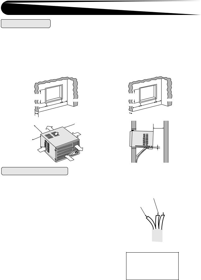
LOCATION
The appliance shall be installed in accordance with national wiring regulations. Improper connection may cause the power cord and electrical outlet to overheat or fire. Install the air conditioner to the opening dimensions shown below.
Never install the unit where any of the air inlet is blocked.
The air conditioner should be installed with a strong external support to minimize noise and vibration, and for the purpose of safe installation, repair, replacement and secure positioning.
Avoid installing the air conditioner where it is exposed to direct sunlight.
AF-A07CE,AF-A09CE |
AF-A12CE |
36.0~37.0 cm |
|
|
|
|
|
(14.2"~14.6") |
|
|
|
More than 20 cm(8") |
|
|
|
|
|
||
|
48 |
.0~49 |
.0 cm |
||
More than 20 cm |
) |
||||
|
|
|
|||
|
|
|
~19.3" |
||
(8") |
(18 |
.9" |
|
||
|
8~20 cm(3"~8") |
|
|
More than 40cm(16") |
Air outlet |
|
More than 20cm(8") |
|
|
||
|
|
Air inlet |
Air inlet |
|
|
|
More than 20cm(8")
Air outlet
Air inlet
Air inlet
POWER CABLING
GROUNDING
WARNING : THIS APPLIANCE MUST BE GROUNDED.
Fit a disconnect switch, having a contact separation of at least 3mm in all poles, to the electricity power line.
Connect the brown wire of the power supply cord to the live terminal, and the grounding wire (green and yellow) to the grounding terminal of the electrical outlet. The remaining wire should be connected to the neutral terminal of the electrical outlet.
FUSE
For safe, trouble free operation, connect the power cord of the unit to a properly rated independent circuit with a time delay fuse or a circuit breaker. See chart for proper amp ratings for each model.
AF-A07CE, AF-A09CE |
10 amp. |
|
|
AF-A12CE |
15 amp. |
|
|
38.5~39.5 cm |
|
|
|
|
|
(15.2"~15.6") |
|
|
|
More than 20 cm(8") |
|
|
|
|
|
||
|
57 |
.0~58 |
.0 cm |
||
More than 20 cm |
) |
||||
|
|
|
|||
|
|
|
~22.8" |
||
(8") |
(22 |
.4" |
|
||

 8~20 cm(3"~8")
More than 40cm (16")
About 1cm (3/8")
Grounding wire |
Neutral |
|||
(green&yellow) |
(blue) |
|||
Live |
|
|
|
|
(brown) |
|
|
|
|
|
|
|
|
|
|
|
|
|
|
|
|
|
|
|
|
|
|
|
|
Maximum Permissible
System Impedance
0.41  ( AF-A09CE )
0.25  ( AF-A12CE )
E-2
Loading...