

Schneider Electric Limit Switches Catalog
Limit Switches
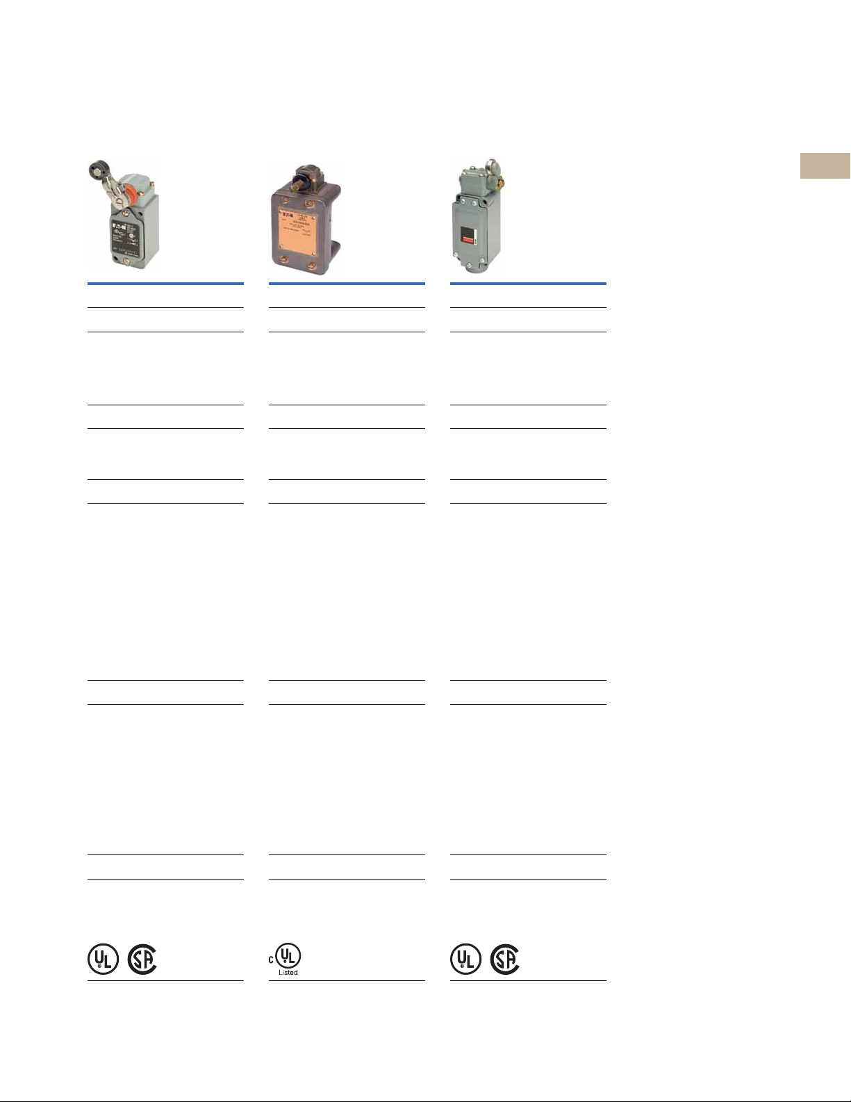
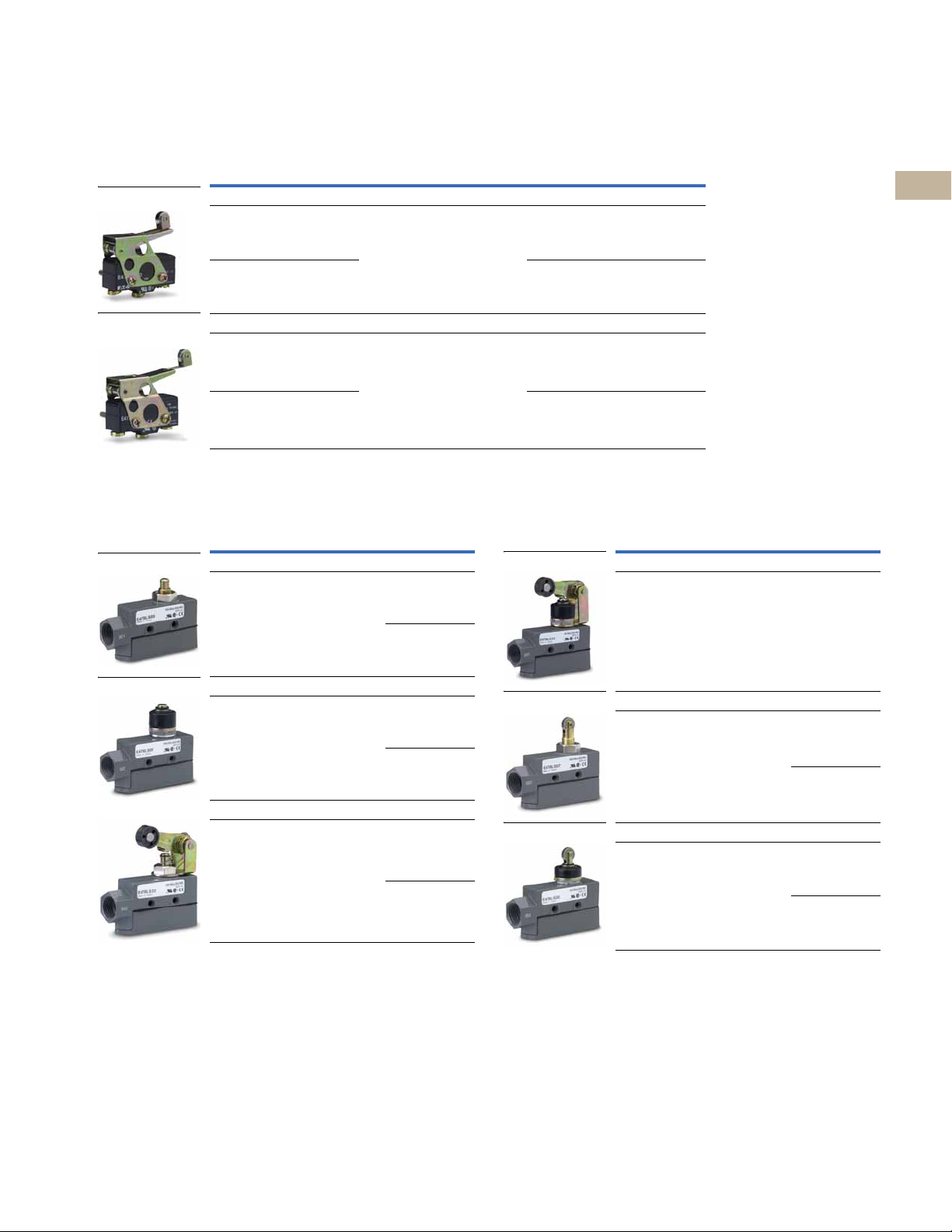
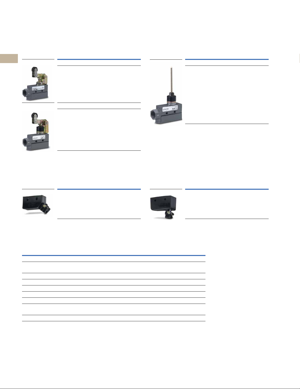
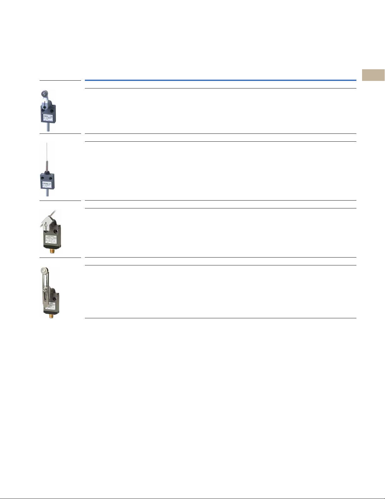
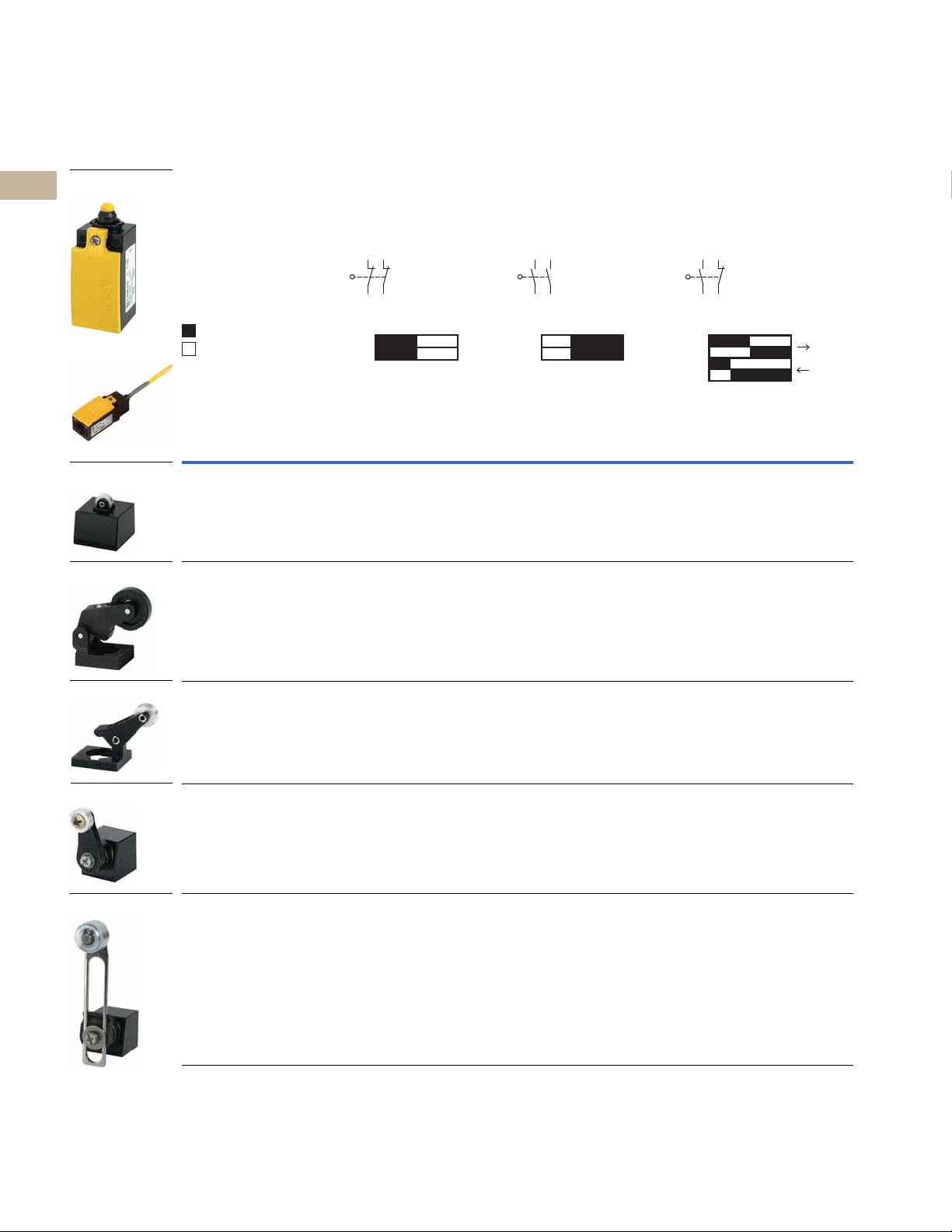
E47 Precision Switch
LS-Titan Miniature DIN Switch
E49 Compact Metal Switch
Heavy-Duty Factory Sealed
6P+ Switch
Compact Prewired Switch
Learn
Online
2.0 Introduction
Technical Reference . . . . . . . . . . . . . . . . . . . . . . . . . . . . . . . . . . . . . . . V8-T2-2
Product Selection Guide . . . . . . . . . . . . . . . . . . . . . . . . . . . . . . . . . . . V8-T2-3
2.1 E47 Precision Switches
Product Description . . . . . . . . . . . . . . . . . . . . . . . . . . . . . . . . . . . . . . . V8-T2-6
Product Selection . . . . . . . . . . . . . . . . . . . . . . . . . . . . . . . . . . . . . . . . . V8-T2-7
2.2 Compact Prewired Switches
Product Description . . . . . . . . . . . . . . . . . . . . . . . . . . . . . . . . . . . . . . . V8-T2-15
Product Selection . . . . . . . . . . . . . . . . . . . . . . . . . . . . . . . . . . . . . . . . . V8-T2-16
2.3 LS-Titan Miniature DIN Switches
Product Description . . . . . . . . . . . . . . . . . . . . . . . . . . . . . . . . . . . . . . . V8-T2-21
Product Selection . . . . . . . . . . . . . . . . . . . . . . . . . . . . . . . . . . . . . . . . . V8-T2-23
2.4 E49 Mini Metal Switches
Product Description . . . . . . . . . . . . . . . . . . . . . . . . . . . . . . . . . . . . . . . V8-T2-43
Product Selection . . . . . . . . . . . . . . . . . . . . . . . . . . . . . . . . . . . . . . . . . V8-T2-44
2.5 E49 Compact Metal Switches
Product Description . . . . . . . . . . . . . . . . . . . . . . . . . . . . . . . . . . . . . . . V8-T2-49
Product Selection . . . . . . . . . . . . . . . . . . . . . . . . . . . . . . . . . . . . . . . . . V8-T2-50
2.6 E50 Heavy-Duty Plug-In Switches
Product Description . . . . . . . . . . . . . . . . . . . . . . . . . . . . . . . . . . . . . . . V8-T2-54
Product Selection . . . . . . . . . . . . . . . . . . . . . . . . . . . . . . . . . . . . . . . . . V8-T2-55
2.7 E50 Heavy-Duty Factory Sealed 6P+ Switches
Product Description . . . . . . . . . . . . . . . . . . . . . . . . . . . . . . . . . . . . . . . V8-T2-68
Product Selection . . . . . . . . . . . . . . . . . . . . . . . . . . . . . . . . . . . . . . . . . V8-T2-69
2.8 Operators
Product Description . . . . . . . . . . . . . . . . . . . . . . . . . . . . . . . . . . . . . . . V8-T2-80
Product Selection . . . . . . . . . . . . . . . . . . . . . . . . . . . . . . . . . . . . . . . . . V8-T2-81
2.9 Non Plug-In Switches
Product Description . . . . . . . . . . . . . . . . . . . . . . . . . . . . . . . . . . . . . . . V8-T2-89
Product Selection . . . . . . . . . . . . . . . . . . . . . . . . . . . . . . . . . . . . . . . . . V8-T2-90
2.10 Hazardous Location Limit Switches
Product Description . . . . . . . . . . . . . . . . . . . . . . . . . . . . . . . . . . . . . . . V8-T2-92
Product Selection . . . . . . . . . . . . . . . . . . . . . . . . . . . . . . . . . . . . . . . . . V8-T2-93
2.11 Special Purpose Limit Switches
Product Description . . . . . . . . . . . . . . . . . . . . . . . . . . . . . . . . . . . . . . . V8-T2-96
Product Selection . . . . . . . . . . . . . . . . . . . . . . . . . . . . . . . . . . . . . . . . . V8-T2-97
Unless otherwise noted, the products contained in this section should not
be used for functional safety applications. These products were not designed
or tested to IEC 60947-5-3 or recommended for functional safety.
2
2
2
2
2
2
2
2
2
2
2
2
2
2
2
2
2
2
2
2
2
2
2
2
2
2
Volume 8—Sensing Solutions CA08100010E—May 2013
2
2
2
2
V8-T2-1
2.0
Differential
Reset Point
Initial Position
Operating
Point
Pre-travel
Over-travel
Initial Position
Over-travel
Reset Point
Operating Point
Pre-travel
Final Position
Differential
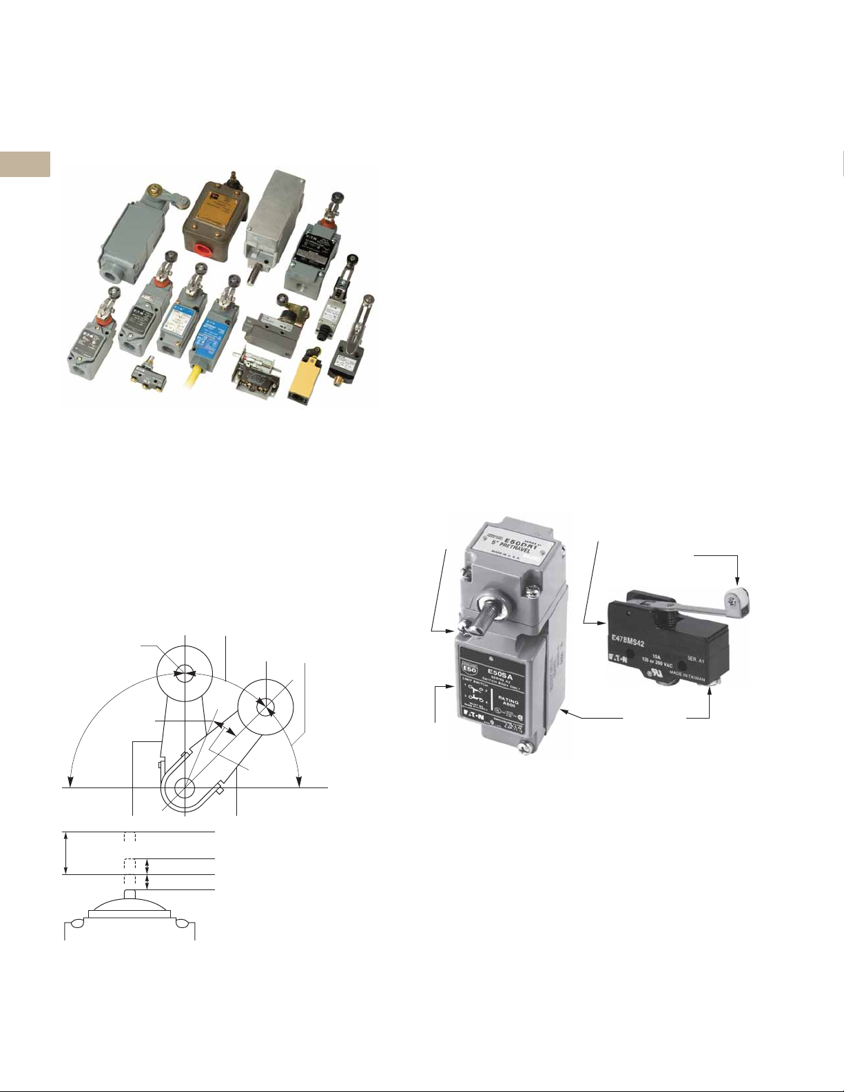
Actuator/
Operating
Head
Switch
Body
Switch
Body
Actuator/
Operating
Head
Receptacle/
Terminals
Technical Reference
2
Limit Switches
2
2
2
2
2
2
2
2
2
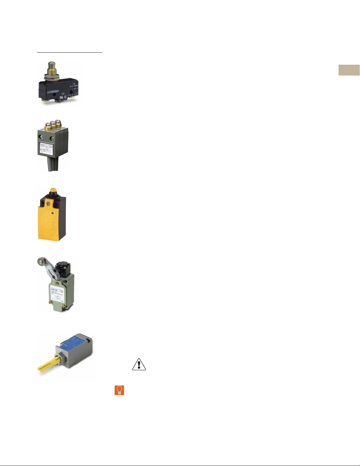
Mechanical Limit Switches
2
are contact sensors widely
used for detecting the
2
presence or position of
objects in industrial
applications.
2
2
2
2
Lever Type Actuator
2
Limit Switches
Introduction
Limit Switches offer high
precision in terms of accuracy
and repeatability. This is
primarily due to the fact that
they make direct contact
with the target. When an
object contacts the limit
switch lever (or plunger)
the lever moves a pre-travel
distance to the operating
point where the contacts are
tripped. Movement of the
lever beyond this point is
called the over-travel.
Limit switches contain the
following major components.
These may be modular or part
of a single-piece switch.
Limit Switch Components
2
2
2
2
2
2
2
2
2
2
2
2
2
Refer to Sensor Learning Course, Page V8-T12-4, for a
complete description of limit switch terminology.
V8-T2-2
Volume 8—Sensing Solutions CA08100010E—May 2013
Actuator
This is the part of the switch
that contacts the target.
Typical actuators are levers
and plungers. Several styles
are available, see Sensor
Learning Course, Page
V8-T12-4, for more
information.
Switch Body
This part contains the
electrical contact mechanism.
For complete information on
electrical outputs, see Sensor
Learning Course, Page
V8-T12-4.
Te rm in al s
The terminals are the point of
connection for the wiring.
These terminals may be on
the body itself, or housed in a
removable receptacle. The
limit switch may also come
equipped with a factory
installed cable or pinconnector.
Limit Switches
Introduction
2.0
Product Selection Guide
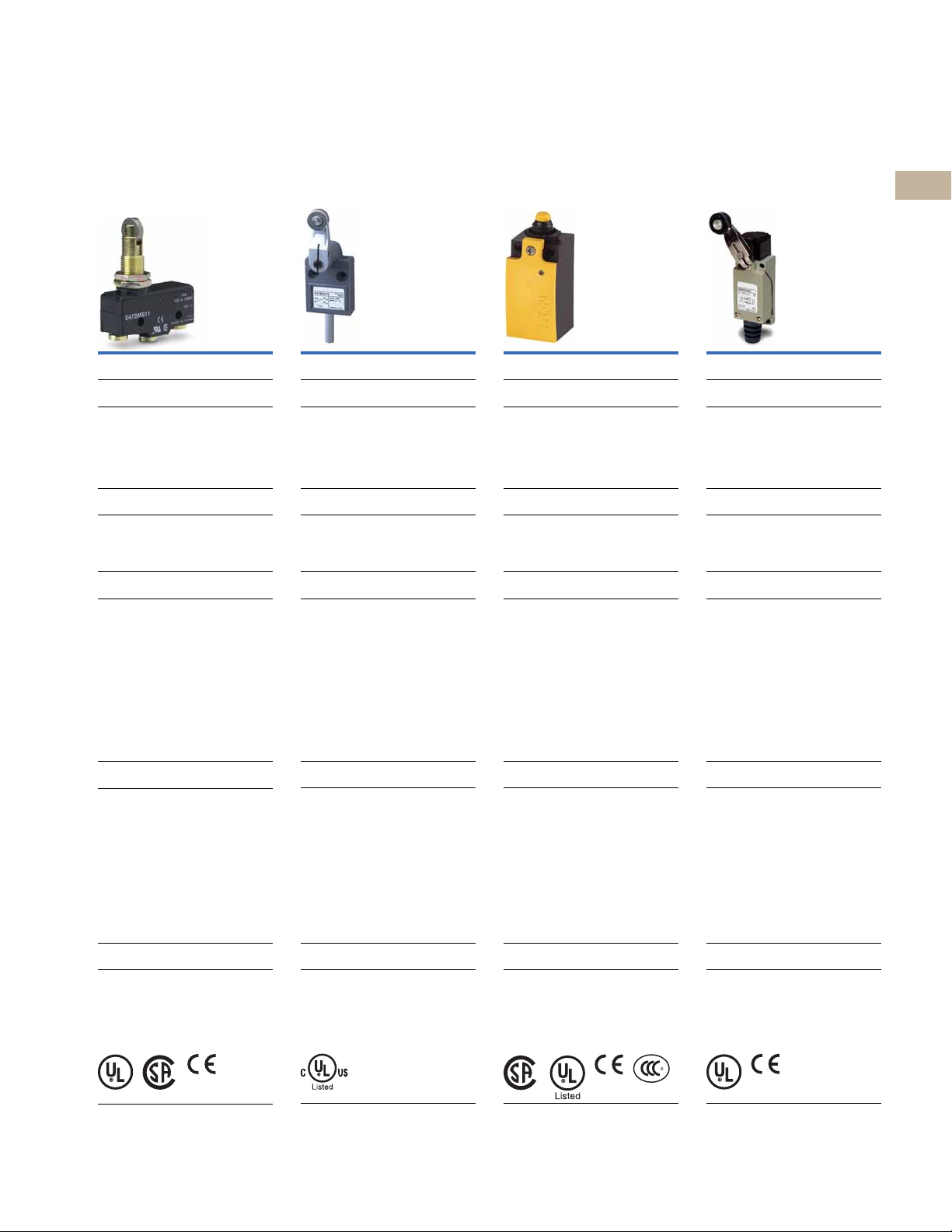
E47 Precision Switches
Page V8- T2 -6
Overview
Specified when accurate repeatability,
choice of operating forces and travel
characteristics and tightly controlled
action of cam or target in space restricted
areas are of prime importance. Cost
effective and compact.
Applications
Overhead, folding and elevator doors,
sliding gates, automated guided vehicles
and commercial instrumentation
Product Features
Self-contained switches or with an enclosed
cast housing for increased durability and
conduit connection
(1/2 in NPT)
High current capacity for power load
switching and motor handling capability
Screw and solder terminations
Booted enclosed version shields actuators
from debris
Mounting centers—1.0 in (25.4 mm),
#8 screw size
Technical Data and Specifications
Mechanical life: 3,000,000 operations min.
Electrical life: 500,000 operations min.
Contact ratings—
NEMA A600, R300, AC-15, DC-13
15A/20A, 125 or 250 Vac
Enclosure ratings—
Enclosed: NEMA 1
Construction—
Basic: Phenolic
Enclosed: Aluminum die cast
Compact Prewired
Switches
Page V8- T2 -15
Overview
Designed to be a versatile, slim device for
hard to fit applications where sealing
integrity is required.
Applications
Machine tool, food processing and
packaging
Product Features
Rugged aluminum alloy die cast housing
Sealed construction with enclosure ratings
of NEMA 4, 6 and 13
Prewired with 3m of 18 AWG, AWM 2517,
300V cable
Stackable ridge for ganged operation
Technical Data and Specifications
Mechanical life: 10,000,000 operations
min.
Electrical life: 200,000 operations
30 operations min.
Contact ratings—
NEMA B300
Enclosure ratings—
NEMA 4, 6 and 13; IP67, IP69K
Construction—
Aluminum alloy die cast
LS-Titan Miniature
DIN Switches E49 Mini Metal Switches
Page V8- T2 -21
Overview
Safety position switches with
insulated plastic or rugged metal
enclosures. Approved for worldwide
safety application.
Applications
Automatic vending machines, electronic
assembly machines, elevators and lifts,
injection molding, packaging and safety
applications
Product Features
Modular plug-in head and body components
Positive opening NC contacts for safety
applications
Operating heads can be rotated 90 degrees
to suit specific direction of operation
Technical Data and Specifications
Mechanical life: 8,000,000 operations
Contact ratings—
AC-15, 6A at 24V, 6A at 230/240V,
4A at 400/415V;
DC-13, 3A at 24V, 800 mA at 110V,
300 mA at 220V
Enclosure ratings—
IP66, IP67 (by model)
Construction—
Plastic or metal (by model)
Page V8-T2-43
Overview
Suitable for OEMs who require a small,
cost-effective solution but cannot sacrifice
durability and mechanical life as they would
if they chose a plastic IEC style switch.
Applications
Automatic vending machines, electronic
assembly machines, elevators and lifts,
injection molding, packaging
Product Features
Pre-wired units with custom cable lengths
available for high volume customers
“Fingerproof” terminals protect against
accidental shock
Double-spring mechanism for contact
reliability
Grounding terminal included
Captive screws on enclosure cover make
wiring hassle-free
SPDT double break
Technical Data and Specifications
Contact ratings—
5A at 250 Vac
5A at 30 Vdc
Enclosure ratings—
IP65
Construction—
Zinc alloy
2
2
2
2
2
2
2
2
2
2
2
2
2
2
2
2
2
2
2
2
2
2
2
2
Approvals
®
Recognized
UL
®
Certified
CSA
CE
Approvals
cULus
Approvals
Safety function, IEC/EN 60947-5-1
TÜV-Rheinland certified (LSE models)
CSA certified
UL listed
CE
CCC
Volume 8—Sensing Solutions CA08100010E—May 2013
Approvals
UL Recognized
CE
2
2
2
2
2
2
V8-T2-3
2.0
Limit Switches
Introduction
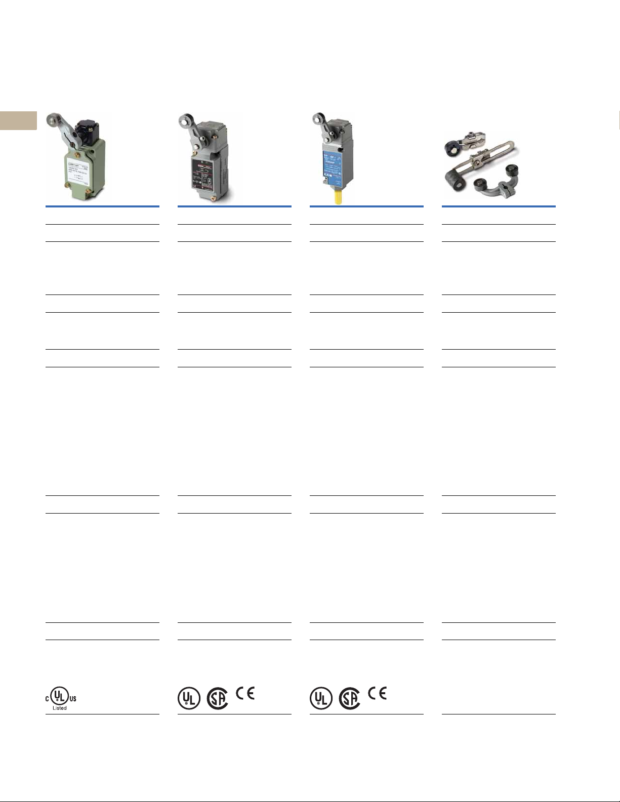
E49 Compact Metal
2
Switches
2
2
2
2
2
Page V8-T2-49
2
Overview
Designed with high mechanical strength for
2
robust environments. The rugged Aluminum
die cast construction provides reliable, oiltight, waterproof and dustproof sealing for
2
a variety of applications. Snap action 1NO1NC contacts provide flexibility in design.
2
Applications
Packaging, material handling conveyors,
2
end-of-travel and guarding operations,
baler/compactor, industrial door lifts
2
Product Features
2
Rigid die cast switch housing
Set position indicator plate for easy
2
maintenance
High mechanical strength
2
Oiltight, waterproof and dustproof
construction
2
2
2
2
Technical Data and Specifications
2
Mechanical life: 15,000,000 operations
min.
Electrical life: 500,000 operations
2
min. at full load
Contact ratings—
2
NEMA A600, R300; AC-15, DC-13
Enclosure ratings—
2
NEMA 4, 4X, 6, 6P, 12, 13; IP65, IP67
Construction—
2
Aluminum die cast
2
Approvals
cULus
2
IP67
2
2
E50 Heavy-Duty Plug-In
Switches
Page V8-T2-54
Overview
Versatile in design. High reliability. Low
maintenance costs with installation ease.
BEST CHOICE for Heavy-Duty Limit Switch
applications. Withstands physical and
chemical abuse of harsh industrial
environments.
Applications
Punch presses, waste water treatment,
machine tool, automotive, retrieval
systems, industrial truck, car wash lines
Product Features
Modular operating heads, switch bodies
and receptacles are interchangeable
without field adjustment
Order as complete assemblies or
components for stocking and
manufacturing flexibility
90 degree total travel, 5 degree pre-travel
characteristics are standard features
®
gasket, boot, and seal material
Viton
offers exceptional chemical resistance
Rotary head operating mode from CW,
CCW or CW and CCW is easily changed
without tools
Technical Data and Specifications
Mechanical life: 13,000,000 operations
min.
Electrical life: 1,000,000 operations
min. at full load (single-pole)
Contact ratings—
NEMA A600, R300
Lighted versions A150, R150
6A, 120 Vac; 10A continuous
Enclosure ratings—
NEMA 1, 3, 3S, 4, 4X, 6, 6P, 13; IP67
Construction—Zinc die cast
Approvals
UL Listed
CSA Certified
IEC 947-5-1
TUV
CE (some models)
E50 Heavy-Duty Factory
Sealed 6P+ Switches Operators
Page V8- T2 -68
Overview
Designed specifically to withstand the
penetrating properties of new cutting fluids
(coolants), acid or caustic washes, salt
spray, severe vibration, shock and
temperature fluctuations, grit and debris.
Applications
Automotive, pulp and paper, food
processing, waste management, primary
metals, machine tool (cutting, forming,
bending)
Product Features
Tamperproof, one-piece switch body
assembly, epoxy filled
Factory sealed. 6P submersible. Pre-wired
with cable, pigtail or pin connector options.
All with ground connection
Utilizes E50 modular operating heads
Special V-seal on switch body/head
connection provides hermetic barrier
against fluid ingress
LED indicating light, 24V–120 Vac/dc
neon version too
Peel off see-through painting mask over
nameplate
Technical Data and Specifications
Mechanical life: 35,000,000 operations min.
Electrical life: 1,000,000 operations
min. at full load
Contact ratings—
NEMA A600, R300
Lighted versions A150, R150
6A, 120 Vac; 10A continuous
Enclosure ratings—
NEMA 1, 2, 3, 3S, 4, 4X, 6, 6P, 13; IP67,
IP69K
Construction—Zinc die cast
Approvals
UL Listed
CSA Certified
IEC 947-5-1
TUV
CE (some models)
Page V8-T2-80
Overview
Wide variety of operator types f or rotary and
wobble style limit switches.
Applications
Used with E50, E50 6P+ and 10316
limit switches
Product Features
Rollers and rods available in metal
and nonmetal contact surfaces
Technical Data and Specifications
Varies by model
Approvals
Varies by model
2
2
V8-T2-4 Volume 8—Sensing Solutions CA08100010E—May 2013
Limit Switches
Introduction
2.0
Non Plug-In Switches
Page V8-T2-89
Overview
The Industrial standard for Non Plug-In
Heavy-Duty Limit Switches. Sold as
complete assembled units only.
Applications
Serving MRO and USER replacement
requirements with broad
d market coverage
Product Features
Side and top rotary, side and top push or
wobble operation
CW, CCW or CW and CCW operating modes
are field convertible
Double break-make snap action contacts,
same polarity each pole
Captive saddle clamp terminals accept up
to #12 wire
Head can be mounted in any of four discrete
positions, intervals of 90 degrees
Technical Data and Specifications
Mechanical life: 10,000,000 operations
min.
Electrical life: 500,000 operations at
full load
Contact ratings—NEMA A600, R300
6A, 120 Vac; 10A continuous
Enclosure ratings—NEMA 1, 4, 13
Construction—
Zinc die cast
Hazardous Location
Switches Special Purpose Switches
Page V8- T2 -92
Overview
Designed for severe environmental service
in locations where there exists a danger of
an internal or external explosion of
flammable gases, vapors, metal alloy or
grain dust.
Applications
Mining, metal cutting, grain storage, forest
products, petrochemical, waste and sewage
management, pharmaceutical
Product Features
Sealed and unsealed versions available
One-way gasket on sealed version keeps
liquids out, yet allows a harmless release of
gases in the event of an internal explosion
Silicon bronze housing provides excellent
corrosion resistant properties in extreme
NEMA 4X applications
Temperature build-up on limit switch
surface is dissipated by housing design and
materials used
Utilizes the operating heads and internal
switch mechanisms of the 10316
Non Plug-In line
Technical Data and Specifications
NEMA 7, Div. 1, Class I, BCD
NEMA 9, Div. 1, Class II, EFG
Contact ratings—NEMA B600
3A, 120 Vac; 5A continuous
Enclosure ratings—LX: NEMA 7, 9
CX: NEMA 1, 4, 7, 9
CB: NEMA 1, 4, 4X, 13
CBX: NEMA 1, 4, 4X, 7, 9, 13
Construction—LX, CX: Aluminum die cast
CB, CBX: Silicon bronze
Page V8- T2 -96
Overview
Variety of special function limit switch
products.
Applications
Serving MRO and USER replacement
requirements with broad market coverage
Product Features
Special function switch lines include:
Cabinet door interlocks — when plunger
is pulled out, red band indicator visually
shows that interlock is defeated
Precision switches—1NO-1NC,
2NO-2NC, or operator only. Variety of
mounting brackets available
Pneumatic time delay—ON delay and OFF
delay. Timing range—0.05 to 60 seconds
Rotating cam shaft switches
Technical Data and Specifications
See Page V8-T2-99 for more information
Enclosure ratings—
NEMA 1 or NEMA 4 versions
Construction—
Zinc die cast
PS: Phenolic
2
2
2
2
2
2
2
2
2
2
2
2
2
2
2
2
2
2
2
2
2
2
2
2
Approvals
UL Listed
CSA Certified
Approvals
®
Listed
cUL
Approvals
UL Listed
CSA Certified (PS and J only)
Volume 8—Sensing Solutions CA08100010E—May 2013 V8-T2-5
2
2
2
2
2
2
2.1
E47 Precision Switches
Drawings
Online
Limit Switches
E47 Precision Switches
2
2
2
2
2
2
2
2
2
2
2
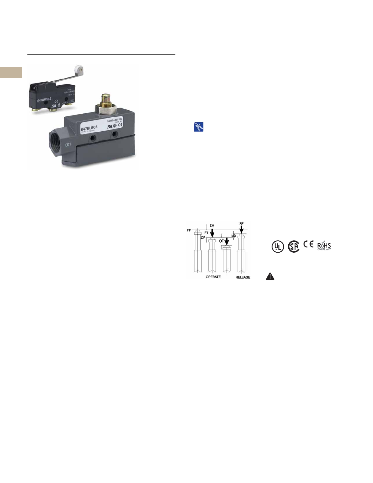
E47 Precision Switches
Product Description
2
E47 Precision Switches from
Eaton’s electrical sector
2
provide high accuracy
switching at an affordable
2
price. A variety of standard
features, such as current
2
capacity, operating force,
travel characteristics and
2
actuators, lets you custom
fit the switch to your
application.
2
The switches are available
2
in their compact basic form,
or enclosed in a rugged,
metal housing.
2
2
2
2
2
2
2
2
Features
●
Compact housings are
deal for use where sp
i
i
s restricted
●
Precision, snap-action
erators provide a
op
repe
atability of electrical
and mechanical operating
haracteristics
c
●
High current capacity
to 20A) allows powe
(up
l
oad switchi
handling capability
●
Enclosed booted versions
ield actua
sh
de
bris
ng and motor
tors from
ace
ccurate
r
Contents
Description Page
E47 Precision Switches
Product Selection
Basic Switches . . . . . . . . . . . . . . . . . . . . . . V8-T2-7
Enclosed Switches. . . . . . . . . . . . . . . . . . . . V8-T2-9
Accessories . . . . . . . . . . . . . . . . . . . . . . . . . . . V8-T2-10
Technical Data and Specifications . . . . . . . . . . V8-T2-10
Dimensions . . . . . . . . . . . . . . . . . . . . . . . . . . . V8-T2-12
Operating Characteristics
Definitions
●
OF—Operating Force
●
RF—Return Force
●
PT—Pre-Travel
●
OT—Over-Travel
●
MD—Movement
ferential
Dif
●
FP—Free Position
●
OP—Operating Position
Standards and Certifications
●
UL Recognized
●
CSA Certified
●
CE
●
RoHS
DANGER
THIS SENSOR IS NOT A
SAFETY DEVICE AND IS NOT
INTENDED TO BE USED AS A
SAFETY DEVICE. This sensor
is designed only to detect
and read certain data in an
electronic manner and
perform no use apart from
that, specifically no safetyrelated use. This sensor
product does not include
self-checking redundant
circuitry, and the failure of
this sensor product could
cause either an energized
or de-energized output
condition, which could result
in death, serious bodily
injury, or property damage.
2
2
2
2
V8-T2-6 Volume 8—Sensing Solutions CA08100010E—May 2013
Limit Switches
Pin Plunger
Extended Plunger
Straight Plunger
Reversed Lever
Straight Lever
Standard Lever
Extended Straight
Plunger
E47 Precision Switches
2.1
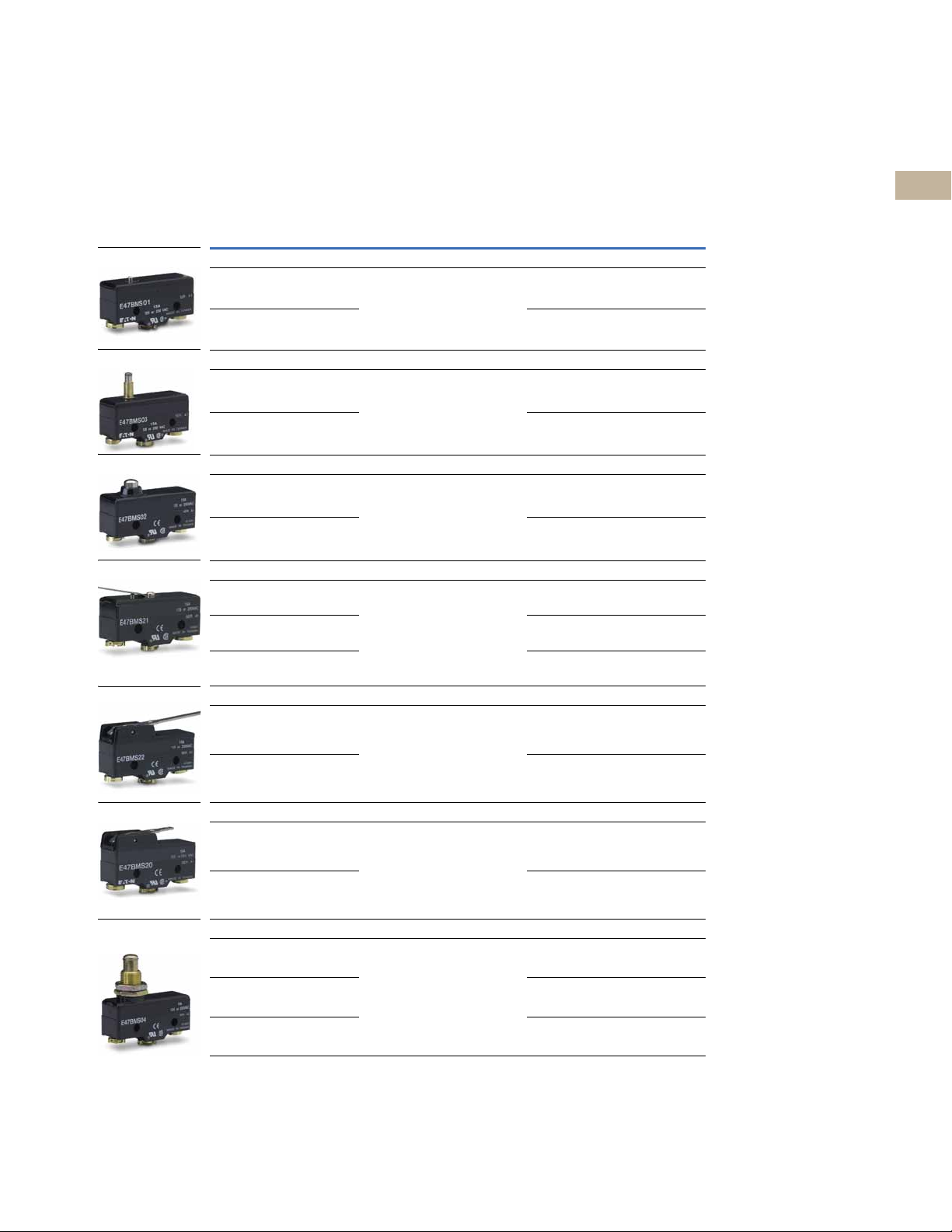
Product Selection
Basic Switches
E47 Precision Switches—Basic
Type Specifications
Pin Plunger
Screw terminal OF max.—12.3 oz (350g)
Solder terminal E47BML01 E47CML01
Extended Plunger
Screw terminal OF max.—12.3 oz (350g)
Solder terminal E47BML03 —
Straight Plunger
Screw terminal OF max.—12.3 oz (350g)
Solder terminal E47BML02 E47CML02
Reversed Lever
Screw terminal OF max.—5.29 oz (150g)
Solder terminal E47BML21 —
Spade terminal E47BMT21 —
RF max.—4.02 oz (114g)
PT max.—0.016 in (0.4 mm)
OT max.—0.005 in (0.13 mm)
MD max.—0.002 in (0.05 mm)
OP—0.626 in (15.9 mm)
RF max.—4.02 oz (114g)
PT max.—0.016 in (0.4 mm)
OT max.—0.063 in (1.6 mm)
MD max.—0.002 in (0.05 mm)
OP—1.11 in (28.2 mm)
RF max.—4.02 oz (114g)
PT max.—0.016 in (0.4 mm)
OT max.—0.063 in (1.6 mm)
MD max.—0.002 in (0.05 mm)
OP—0.846 in (21.5 mm)
RF max.—0.49 oz (14g)
PT max.—0.16 in (4 mm)
OT max.—0.063 in (1.6 mm)
MD max.—0.051 in (1.3 mm)
FP max.—0.81 in (20.6 mm)
OP—0.685 in (17.4 mm)
1
15A
Catalog Number
E47BMS01 E47CMS01
E47BMS03 —
E47BMS02 E47CMS02
E47BMS21 —
20A
Catalog Number
2
2
2
2
2
2
2
2
2
2
2
2
2
2
2
2
2
Straight Lever
Screw terminal OF max.—2.47 oz (70g)
Solder terminal E47BML22 —
Standard Lever
Screw terminal OF max.—3.53 oz (100g)
Solder terminal E47BML20 —
Extended Straight Plunger
Screw terminal OF max.—12.3 oz (350g)
Screw terminal (with space lugs) E47BMT04 —
Solder terminal E47BML04 E47CML04
Notes
1
OF = Operating Force; RF = Return Force; PT = Pre-Travel; OT = Over-Travel; MD = Movement Differential;
FP = Free Position; OP = Operating Position.
2
Contact Eaton’s Sensor Applications Department at 1-800-426-9184 for approval status.
RF min.—0.49 oz (14g)
PT max.—0.394 in (10 mm)
OT max.—0.220 in (5.6 mm)
MD max.—0.051 in (1.3 mm)
FP max.—1.11 in (28.2 mm)
OP—0.748 in (19 mm)
RF min.—0.99 oz (28g)
PT max.—0.197 in (5.0 mm)
OT max.—0.079 in (2.0 mm)
MD max.—0.039 in (1.0 mm)
FP max.—0.976 in (24.8 mm)
OP—0.748 in (19 mm)
RF max.—4.02 oz (114g)
PT max.—0.016 in (0.4 mm)
OT max.—0.217 in (5.5 mm)
MD max.—0.002 in (0.05 mm)
OP—0.858 in (21.8 mm)
E47BMS22 E47CMS22
E47BMS20 —
E47BMS04 E47CMS04
2
2
2
2
2
2
2
2
2
2
2
2
2
2
Volume 8—Sensing Solutions CA08100010E—May 2013 V8-T2-7
2.1
Roller Plunger
Cross Roller Plunger
Reversed Roller Lever
Extended Roller Lever
Roller Lever
One-Way Roller
Integral Leaf
Limit Switches
E47 Precision Switches
2
2
2
2
2
2
2
2
2
2
2
2
2
2
2
2
2
2
2
2
2
2
2
2
2
2
2
2
2
2
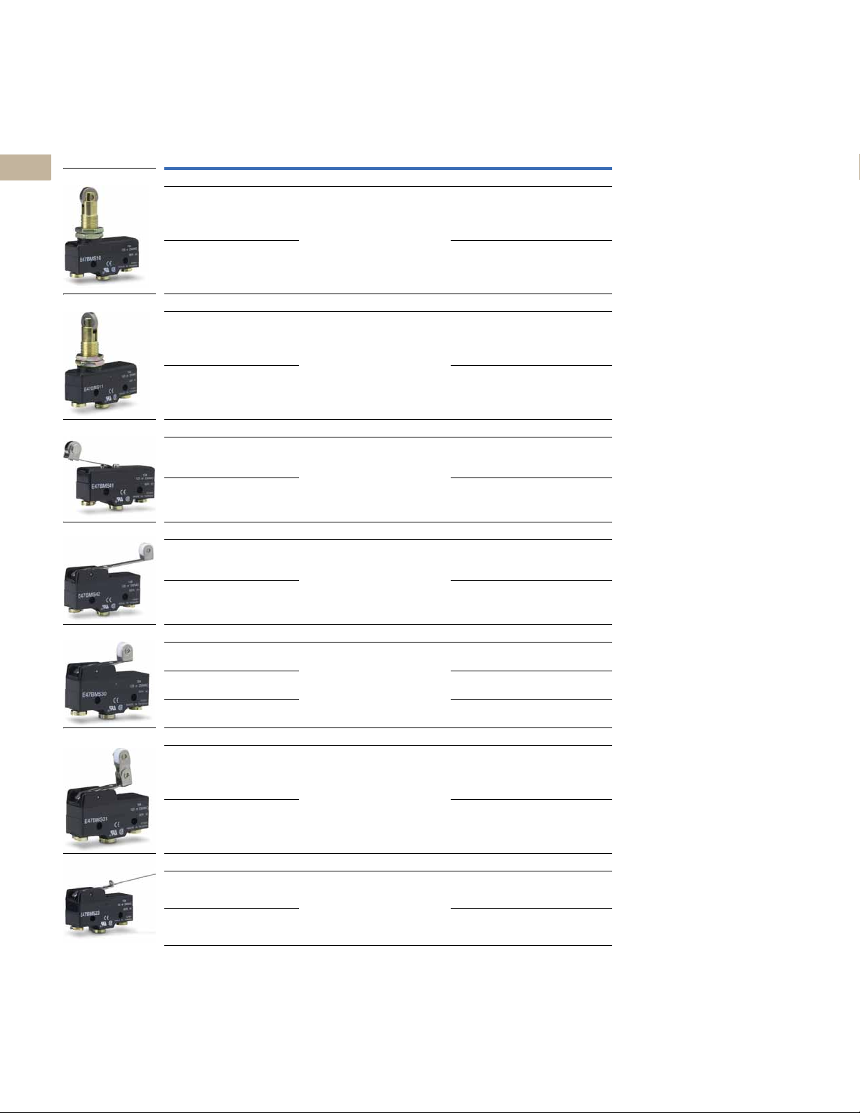
E47 Precision Switches—Basic, continued
Type Specifications
Roller Plunger
Screw terminal OF max.—12.3 oz (350g)
Solder terminal E47BML10 —
Cross Roller Plunger
Screw terminal OF max.—12.3 oz (350g)
Solder terminal E47BML11 —
Reversed Roller Lever
Screw terminal OF max.—5.29 oz (150g)
Solder terminal E47BML41 —
Extended Roller Lever
Screw terminal OF max.—5.64 oz (160g)
Solder terminal E47BML42 —
Roller Lever
Screw terminal OF max.—5.64 oz (160g)
Solder terminal E47BML30 —
Spade terminal E47BMT30 E47CMT30
One-Way Roller
Screw terminal OF max.—5.64 oz (160g)
Solder terminal E47BML31 —
Integral Leaf
Screw terminal OF max.—0.35 oz (10g)
Solder terminal E47BML23 —
Note
1
OF = Operating Force; RF = Return Force; PT = Pre-Travel; OT = Over-Travel; MD = Movement Differential;
FP = Free Position; OP = Operating Position.
RF max.—4.02 oz (114g)
PT max.—0.016 in (0.4 mm)
OT max.—0.14 in (3.6 mm)
MD max.—0.002 in (0.05 mm)
OP—1.315 in (33.4 mm)
RF max.—4.02 oz (114g)
PT max.—0.016 in (0.4 mm)
OT max.—0.14 in (3.6 mm)
MD max.—0.002 in (0.05 mm)
OP—1.315 in (33.4 mm)
RF max.—0.49 oz (14g)
PT max.—0.16 in (4 mm)
OT max.—0.063 in (1.6 mm)
MD max.—0.051 in (1.3 mm)
FP max.—1.252 in (31.8 mm)
OP—1.126 in (28.6 mm)
RF min.—0.78 oz (22g)
PT max.—0.28 in (7.1 mm)
OT max.—0.16 in (4 mm)
MD max.—0.04 in (1.02 mm)
FP max.—1.437 in (36.5 mm)
OP—1.189 in (30.2 mm)
RF min.—1.48 oz (42g)
PT max.—0.106 in (2.7 mm)
OT max.—0.094 in (2.4 mm)
MD max.—0.02 in (0.5 mm)
FP max.—1.28 in (32.5 mm)
OP—1.189 in (30.2 mm)
RF min.—1.48 oz (42g)
PT max.—0.106 in (2.7 mm)
OT max.—0.094 in (2.4 mm)
MD max.—0.02 in (0.5 mm)
FP—1.717 in (43.6 mm)
OP—1.697 in (43.1 mm)
RF min.—0.106 oz (3.0g)
PT max.—0.787 in (20.0 mm)
OT max.—0.22 in (5.6 mm)
MD max.—0.118 in (3.0 mm)
OP—0.748 in (19.0 mm)
1
15A
Catalog Number
E47BMS10 E47CMS10
E47BMS11 E47CMS11
E47BMS41 —
E47BMS42 E47CMS42
E47BMS30 E47CMS30
E47BMS31 —
E47BMS23 E47CMS23
20A
Catalog Number
V8-T2-8 Volume 8—Sensing Solutions CA08100010E—May 2013
Limit Switches
Adjustable Roller
Extended
Adjustable Roller
Plunger Actuator
Booted Plunger
Roller Lever
Booted Roller Lever
Roller Plunger
Booted Roller Plunger
E47 Precision Switches
2.1
Enclosed Switches
E47 Precision Switches—Basic, continued
Type Specifications
Adjustable Roller
Screw terminal OF max.—17.64 oz (500g)
Solder terminal E47BML40 —
Extended Adjustable Roller
Screw terminal OF max.—21.16 oz (600g)
Solder terminal E47BML43 —
E47 Precision Switches—Enclosed
Specifications
Plunger Actuator
OF max.—8.82–12.3 oz (250–350g)
RF min.—4.02 oz (114g)
PT max.—0.016 in (0.4 mm)
OT max.—0.217 in (5.5 mm)
MD max.—0.002 in (0.05 mm)
OP—1.504 in (38.2 mm)
Booted Plunger
OF max.—28.22 oz (800g)
RF min.—8.46 oz (240g)
PT max.—0.079 in (2.0 mm)
OT max.—0.197 in (5.0 mm)
MD max.—0.004 in (0.1 mm)
OP—1.803 in (45.8 mm)
Roller Lever
OF max.—20.1 oz (570g)
RF min.—6.0 oz (170g)
PT max.—0.157 in (4.0 mm)
OT max.—0.236 in (6.0 mm)
MD max.—0.016 in (0.4 mm)
1
RF min.—6.0 oz (170g)
PT max.—0.197 in (5.0 mm)
OT max.—0.5 in (12.7 mm)
MD max.—0.087 in (2.2 mm)
FP max.—1.752 in (44.5 mm)
OP—1.591 in (40.4 mm)
RF min.—10.58 oz (300g)
PT max.—0.118 in (3.0 mm)
OT max.—0.236 in (6.0 mm)
MD max.—0.079 in (2.0 mm)
FP max.—1.614 in (41 mm)
OP—1.591 in (40.4 mm)
1
Catalog Number
E47BLS05
23
E47CLS05
E47BLS06
23
E47CLS06
E47BLS32
23
E47CLS32
15A
Catalog Number
E47BMS40 —
E47BMS43 —
20A
Catalog Number
Specifications
Booted Roller Lever
OF max.—22.57 oz (640g)
RF min.—8.11 oz (230g)
PT max.—0.197 in (5.0 mm)
OT max.—0.236 in (6.0 mm)
MD max.—0.016 in (0.4 mm)
Roller Plunger
OF max.—8.82–12.3 oz (250–350g)
RF min.—4.02 oz (114g)
PT max.—0.02 in (0.5 mm)
OT max.—0.142 in (3.6 mm)
MD max.—0.002 in (0.05 mm)
OP—1.957 in (49.7 mm)
Booted Roller Plunger
OF max.—17.64 oz (500g)
RF min.—3.53 oz (100g)
PT max.—0.039 in (1.0 mm)
OT max.—0.138 in (3.5 mm)
MD max.—0.005 in (0.12 mm)
OP—1.957 in (49.7 mm)
1
Catalog Number
E47BLS33
E47BLS07
4
E47BLS11
E47BLS08
4
E47BLS12
2
2
2
2
2
2
2
2
2
2
2
2
2
2
2
2
2
2
2
2
2
2
2
2
Notes
1
OF = Operating Force; RF = Return Force; PT = Pre-Travel; OT = Over-Travel; MD = Movement Differential;
FP = Free Position; OP = Operating Position.
2
Contact Eaton’s Sensor Applications Department at 1-800-426-9184 for approval status.
3
20 ampere version.
4
Cross roller unit.
Volume 8—Sensing Solutions CA08100010E—May 2013 V8-T2-9
2
2
2
2
2
2
2.1
One-Way Roller
Booted One-Way
Roller
Booted Wobble
45°
90°
Limit Switches
E47 Precision Switches
2
2
2
2
2
2
2
2
2
2
2
2
2
2
2
Accessories
E47 Precision Switches—
Enclosed, continued
Specifications
One-Way Roller
OF max.—20.1 oz (570g)
RF min.—6.0 oz (170g)
PT max.—0.157 in (4.0 mm)
OT max.—0.236 in (6.0 mm)
MD max.—0.016 in (0.4 mm)
Booted One-Way Roller
OF max.—22.57 oz (640g)
RF min.—8.11 oz (230g)
PT max.—0.197 in (5.0 mm)
OT max.—0.236 in (6.0 mm)
MD max.—0.016 in (0.4 mm)
Terminal Wire Covers for Basic Switches
Description Catalog Number
Terminal wire cover with
45° conduit interface
1
Catalog Number
E47BLS34
E47BLS35
E47PA1
E47 Precision Switches—
Enclosed, continued
Specifications
Booted Wobble
OF max.—2.11 oz (60g)
RF min.—0.88 oz (25g)
PT max.—0.520 in (13.2 mm)
OT max.—0.315 in (8.0 mm)
MD max.—0.039 in (1.0 mm)
Description Catalog Number
Terminal wire cover with
90° conduit interface
1
Catalog Number
E47BLS14
E47PA2
2
2
2
2
2
2
2
2
2
2
2
2
2
2
Technical Data and Specifications
E47 Precision Switches
Description Specification
Operating speed 0.01m/second to 1m/second
Operating Frequency
Mechanical 120 operations/minute
Electrical 20 operations/minute
Mechanical life 3,000,000 operations minimum
Electrical life 500,000 operations minimum
Contact resistance 15M ohms maximum, initial
Insulation resistance 100M ohms minimum at 500 Vdc
Dielectric Strength
Between non-current carrying parts 1000 Vac, 50/60 Hz for 1 minute
Between current carrying parts and ground 2000 Vac, 50/60 Hz for 1 minute
Notes
1
OF = Operating Force; RF = Return Force; PT = Pre-Travel; OT = Over-Travel;
MD = Movement Differential; FP = Free Position; OP = Operating Position.
2
Cross roller unit.
2
V8-T2-10 Volume 8—Sensing Solutions CA08100010E—May 2013
Limit Switches
Solder TypeScrew Type
E47 Precision Switches
2.1
E47 Precision Switches, continued
Description Specification
Ambient Operating Temperature
Basic –13° to 176°F (–25° to 80°C)
Enclosed 5° to 176°F (–15° to 80°C)
Environmental rating enclosed, booted NEMA 1
Mounting centers 1.0 in (25.4 mm), #8 screw size
Terminal screws Bottom facing M4 x 0.7 (8–32)
Threaded bushing 15/32 in
Material of construction Mineral filled phenolic
Enclosure rating Aluminum die casting (ADC-3/A380); Seal boot: nitrile, butyl rubber (NBR)
Conduit fitting on enclosed type 1/2 in NPT
Maximum Ampere Ratings
Model
15A 125 Vac 15 3 1.5 15 5 2.5 30 max. 15 max.
20A 125 Vac 20 7.5 7.5 20 12.5 12.5 60 max. 30 max.
Rated
Voltage
250 Vac 15 2.5 1.25 15 3 1.5
500 Vac 3 1.5 0.75 2.5 1.5 0.75
8 Vdc 15 3 1.5 15 5 2.5
14 Vdc 15 3 1.5 10 5 2.5
30 Vdc 6 (2) 3 1.5 5 5 2.5
125 Vdc 0.4 0.4 0.4 0.05 0.05 0.05
250 Vdc 0.2 0.2 0.2 0.03 0.03 0.03
250 Vac 20 7.5 7.5 20 8.3 8.3
500 Vac6 445 22
8 Vdc 20 3 1.5 20 12.5 12.5
14 Vdc 20 3 1.5 15 12.5 12.5
30 Vdc 6 3 1.5 5 5 5
125 Vdc 0.5 0.5 0.5 0.05 0.05 0.05
250 Vdc 0.25 0.25 0.25 0.03 0.03 0.03
12
Non-Inductive Load (A) Inductive Load (A)
Resistive Load Lamp Load Inductive Load Motor Load Inrush Current (A)
NC and NO NC NO NC and NO NC NO NC NO
Screws with cup washers will accept 22–12 AWG (2.5 sq. mm maximum)
Maximum torque: 10 in-lbs.
2
2
2
2
2
2
2
2
2
2
2
2
2
2
2
2
2
2
2
2
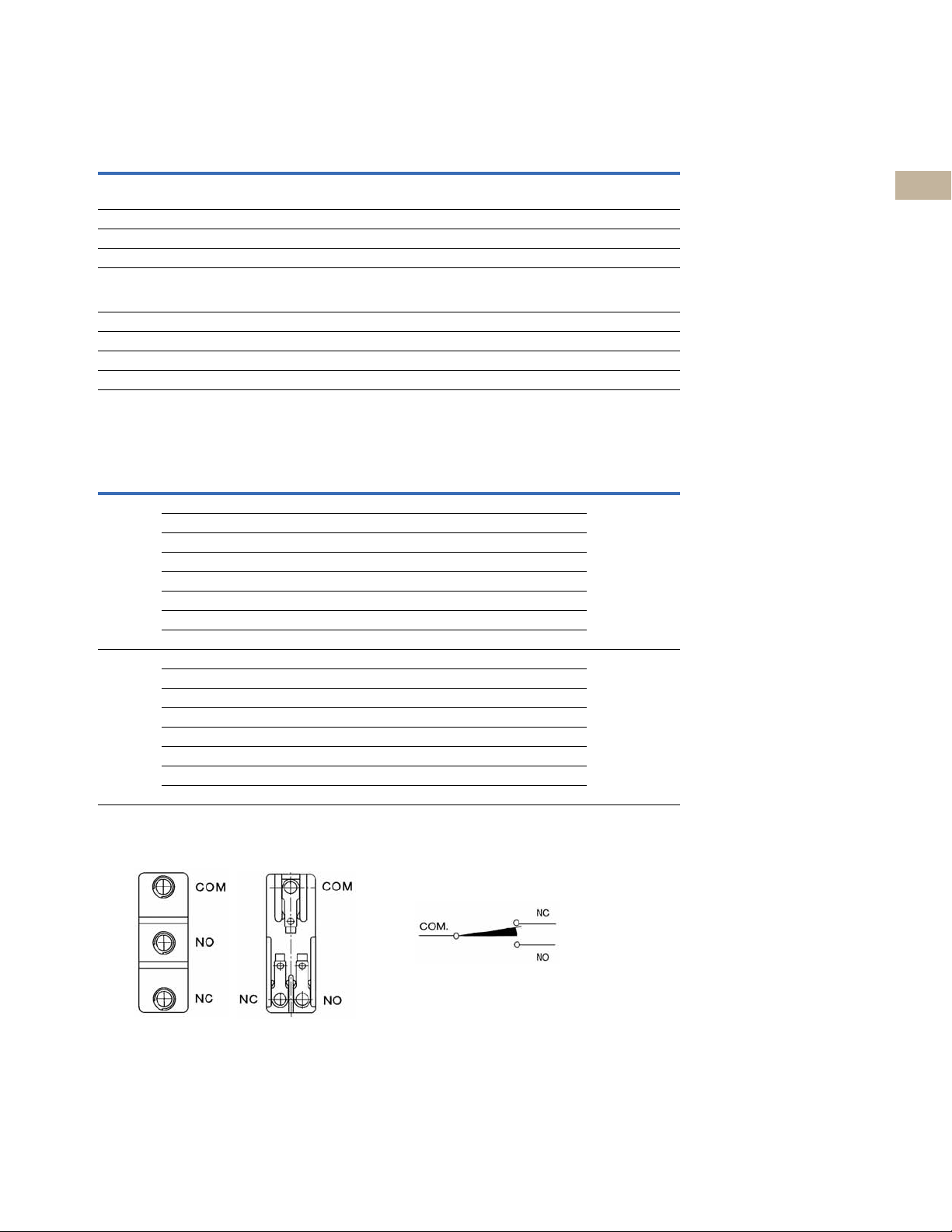
Terminal Configurations
Contact Configuration—
Form C Precision Snap Action
(Spade type not shown, available on some models)
Notes
1
Inductive load has a power factor of 0.04 minimum (AC) and a time constant of 7 m/second (DC).
2
Lamp load has an inrush current of six times steady-state current.
Volume 8—Sensing Solutions CA08100010E—May 2013 V8-T2-11
2
2
2
2
2
2
2
2
2
2
Limit Switches
2.1
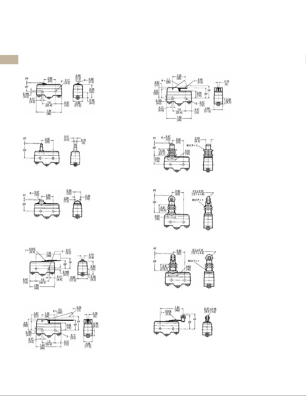
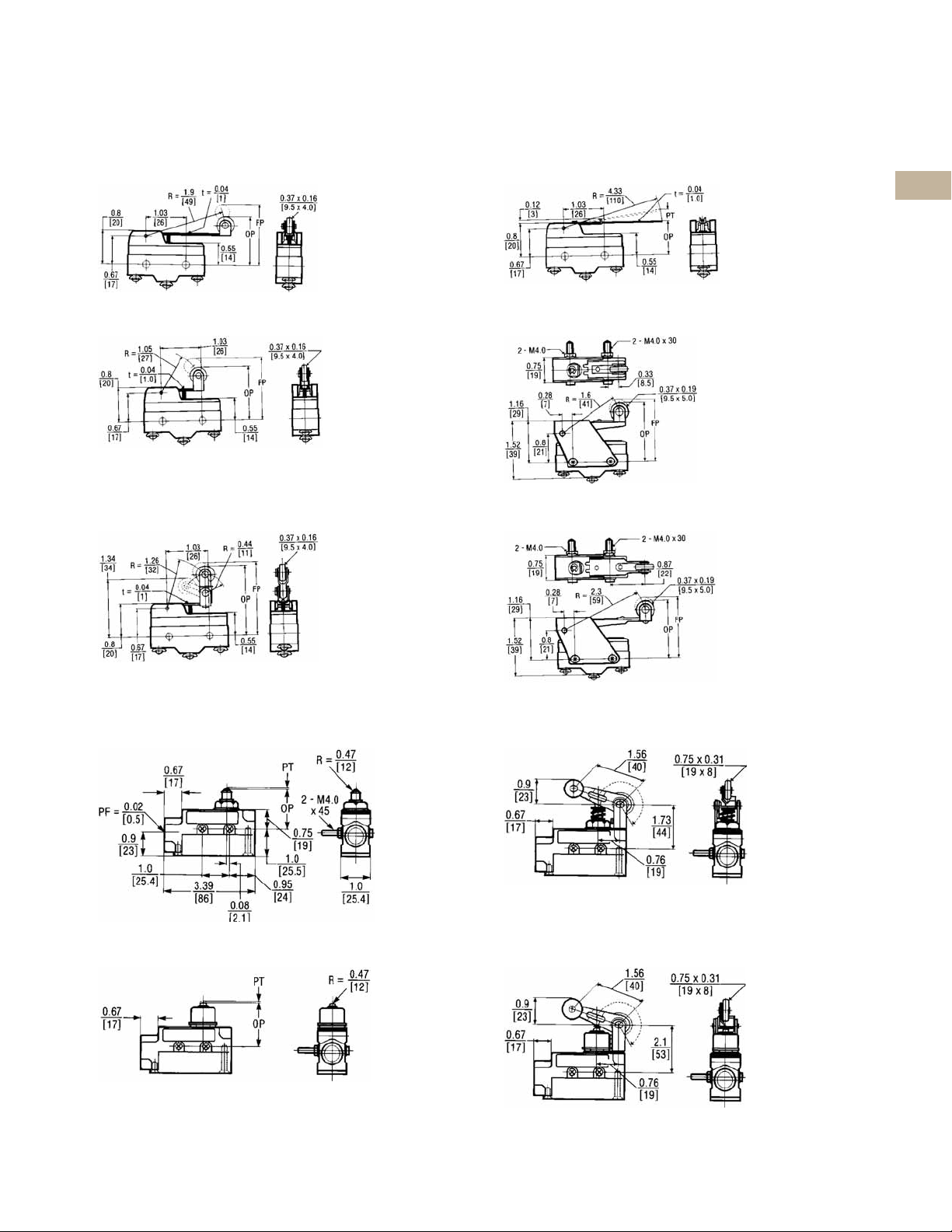
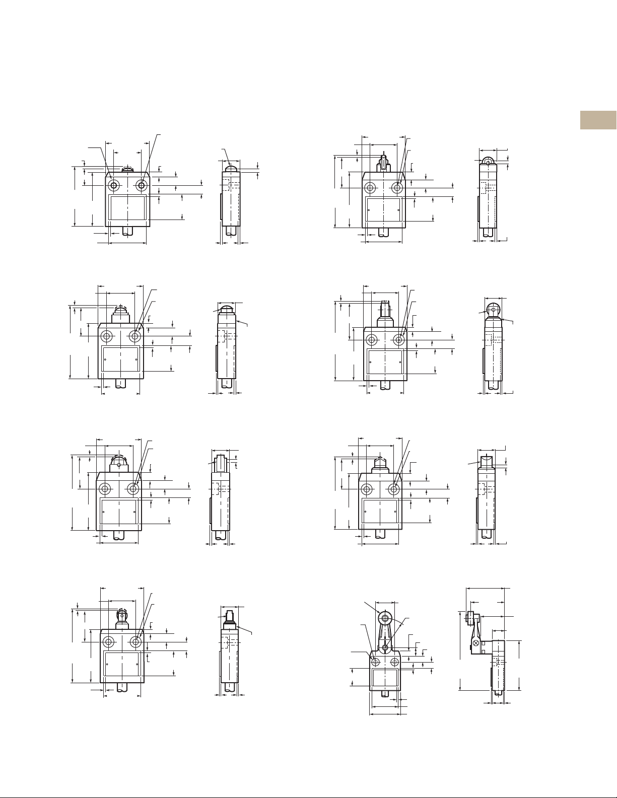
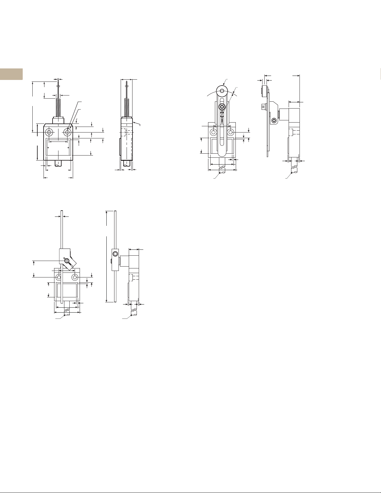
Dimensions
2
Approximate Dimensions in Inches [mm]
2
Basic Switches
Pin Plunger
2
2
2
2
2
2
Extended Plunger
2
2
2
E47 Precision Switches
Standard Lever
Extended Straight Plunger
2
2
Straight Plunger
2
2
2
2
2
Reversed Lever
2
2
2
2
2
2
Straight Lever
2
Roller Plunger
Cross Roller Plunger
Reversed Roller Lever
2
2
2
2
2
V8-T2-12 Volume 8—Sensing Solutions CA08100010E—May 2013
Limit Switches
E47 Precision Switches
2.1
Approximate Dimensions in Inches [mm]
Extended Roller Lever
Roller Lever
One-Way Roller
Integral Leaf
Adjustable Roller
Extended Adjustable Roller
2
2
2
2
2
2
2
2
2
2
2
2
2
2
Enclosed Switches
Plunger Actuator
Booted Plunger
Roller Lever
Booted Roller Lever
2
2
2
2
2
2
2
2
2
2
2
2
2
2
Volume 8—Sensing Solutions CA08100010E—May 2013 V8-T2-13
2
2
Limit Switches
0.91
[23]
0.67
[17]
0.08
[2.1]
5.91
[150]
1.00
[25.5]
1.00 [25.4] 1.00 [25.4] 0.96 [24.5]
3.37
[85.5]
0.25 [6.5]
Dia.
PT
0.37
[9.5]
2-M4.0 x 45
21
14
12
14
53
25.4
2-ø4.2
7
21
18
25
21
12
14
14
25.4
53
A
A
BB
12
39
46
21
7
2-ø4.2
2.1
Approximate Dimensions in Inches [mm]
2
Roller Plunger
2
2
2
2
2
2
2
Booted Roller Plunger
2
2
2
E47 Precision Switches
Booted One-Way Roller
Booted Wobble
2
2
One-Way Roller
2
2
2
2
2
2
Accessories
2
Approximate Dimensions in mm
Terminal Wire Cover with 45° Conduit Interface Terminal Wire Cover with 90° Conduit Interface
2
2
2
2
2
2
2
2
2
2
V8-T2-14 Volume 8—Sensing Solutions CA08100010E—May 2013
Limit Switches
Compact Prewired Switches
Drawings
Online
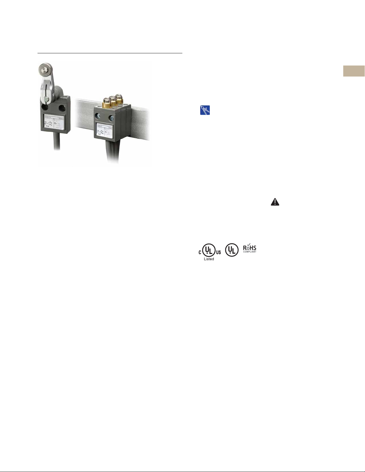
Compact Prewired Switches
2.2
Compact Prewired Switches
Product Description
The E47 Compact Prewired
Limit Switch by Eaton’s
electrical sector is designed
to be a versatile, slim device
for hard to fit applications
where sealing integrity is
required. The rugged die
cast aluminum alloy housing,
cable connection and switch
mechanism are encapsulated
for protection against extreme
temperature (
[
14° to 158°F
moisture, shock and
vibration. This factory wired
(3m) device has NEMA
enclosure ratings of 4, 6
and 13, making it suitable
for applications such as
machine tool, food
processing and packaging.
–10° to 70°C
]), contaminants,
®
Features
●
Rugged aluminum alloy die
cast housing
●
Sealed construction with
closure ratings of
en
4,
6 and 13
●
Prewired with 3m of
AWG, AWM 2517,
18
300V cable, or microconnector version also
ilable
ava
●
Stackable ridge for ganged
eration
op
NEMA
Contents
Description Page
Compact Prewired Switches
Product Selection . . . . . . . . . . . . . . . . . . . . . . . V8-T2-16
Technical Data and Specifications . . . . . . . . . . V8-T2-18
Wiring Diagram . . . . . . . . . . . . . . . . . . . . . . . . V8-T2-18
Dimensions . . . . . . . . . . . . . . . . . . . . . . . . . . . V8-T2-19
Standards and Certifications
●
cULus (cable versions only)
●
UL (cable versions only)
●
NEMA 4, 6 and 13
●
IEC IP67, IP69K
●
RoHS
DANGER
THIS SENSOR IS NOT A
SAFETY DEVICE AND IS NOT
INTENDED TO BE USED AS A
SAFETY DEVICE. This sensor
is designed only to detect
and read certain data in an
electronic manner and
perform no use apart from
that, specifically no safetyrelated use. This sensor
product does not include
self-checking redundant
circuitry, and the failure of
this sensor product could
cause either an energized
or de-energized output
condition, which could result
in death, serious bodily
injury, or property damage.
2
2
2
2
2
2
2
2
2
2
2
2
2
2
2
2
2
2
2
2
2
2
2
2
2
2
2
2
2
2
Volume 8—Sensing Solutions CA08100010E—May 2013 V8-T2-15
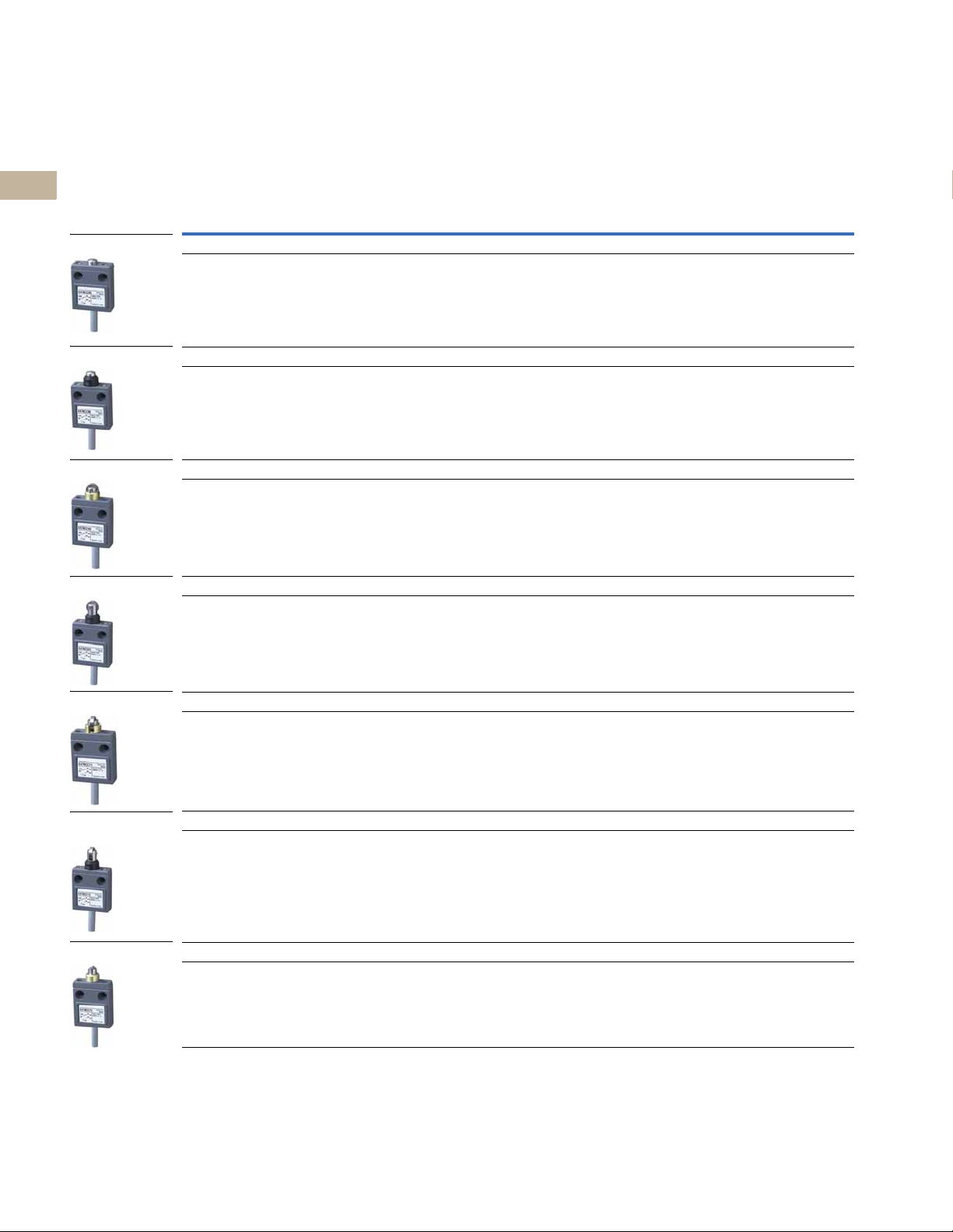
2.2
Pin Plunger
Sealed Plunger
Roller Plunger
Sealed Roller Plunger
Cross Roller Plunger
Sealed Cross Roller
Plunger
Bevel Plunger
Actuator Type
Product Selection
2
2
2
2
2
2
Limit Switches
Compact Prewired Switches
Compact Prewired Switches
Operating Force
(Maximum)
Pin Plunger
42.3 oz
(1.2 kg)
Reset Force
(Minimum)
15.9 oz
(450g)
Over-Travel
(Maximum) Pre-Travel
0.118 in
(3 mm)
0.07 in
(1.8 mm)
Movement
Differential
(Maximum)
0.008 in
(0.2 mm)
Operating
Position
0.62 ± 0.04 in
(15.7 ± 1 mm)
Standard Version
Catalog Number
E47BCC05 E47BCC05P4
Connector Version
Catalog Number
2
2
2
2
2
2
2
2
2
2
2
2
2
2
Sealed Plunger
63.5 oz
(1.8 kg)
Roller Plunger
42.3 oz
(1.2 kg)
Sealed Roller Plunger
63.5 oz
(1.8 kg)
Cross Roller Plunger
42.3 oz
(1.2 kg)
15.9 oz
(450g)
15.9 oz
(450g)
15.9 oz
(450g)
15.9 oz
(450g)
0.118 in
(3 mm)
0.118 in
(3 mm)
0.118 in
(3 mm)
0.118 in
(3 mm)
0.07 in
(1.8 mm)
0.07 in
(1.8 mm)
0.07 in
(1.8 mm)
0.07 in
(1.8 mm)
0.008 in
(0.2 mm)
0.008 in
(0.2 mm)
0.008 in
(0.2 mm)
0.008 in
(0.2 mm)
0.99 ± 0.04 in
(24.9 ± 1 mm)
1.12 ± 0.04 in
(28.5 ± 1 mm)
1.35 ± 0.04 in
(34.3 ± 1 mm)
1.12 ± 0.04 in
(28.5 ± 1 mm)
E47BCC06 E47BCC06P4
E47BCC07 E47BCC07P4
E47BCC08 E47BCC08P4
E47BCC11 E47BCC11P4
2
2
2
2
2
2
2
2
2
2
V8-T2-16 Volume 8—Sensing Solutions CA08100010E—May 2013
Sealed Cross Roller Plunger
63.5 oz
(1.8 kg)
Bevel Plunger
42.3 oz
(1.2 kg)
15.9 oz
(450g)
15.9 oz
50g)
(4
0.118 in
(3 mm)
0.118 in
(3 mm)
0.07 in
(1.8 mm)
0.07 in
(1.8 mm)
0.008 in
(0.2 mm)
0.008 in
(0.2 mm)
1.35 ± 0.04 in
(34.3 ± 1 mm)
1.12 ± 0.04 in
(28.5 ± 1 mm)
E47BCC12 E47BCC12P4
E47BCC13 E47BCC13P4
Limit Switches
Wobble Stick
Rod Lever
Actuator Type
Roller Lever
Adjustable Level Arm
Compact Prewired Switches
2.2
Compact Prewired Switches, continued
Operating Force
(Maximum)
Roller Lever
20.5 oz
(580g)
Wobble Stick
5.3 oz
(150g)
Rod Lever
20.5 oz
(580g)
Reset Force
(Minimum)
5.3 oz
(150g)
——15° max.— — E47BCC20 E47BCC20P4
5.3 oz
(150g)
Over-Travel
(Maximum) Pre-Travel
40° 25° max. 3° — E47BCC15 E47BCC15P4
40° 25° max. 3° — — E47BCC21P4
Movement
Differential
(Maximum)
Operating
Position
Standard Version
Catalog Number
Connector Version
Catalog Number
2
2
2
2
2
2
2
2
2
2
2
2
2
2
Adjustable Level Arm
20.5 oz
(580g)
5.3 oz
(150g)
40° 25° max. 3° — E47BCC22 E47BCC22P4
2
2
2
2
2
2
2
2
2
2
2
2
2
2
2
2
Volume 8—Sensing Solutions CA08100010E—May 2013 V8-T2-17

Limit Switches
Common
(Black)
NC (Red)
NO (Blue)
Ground
(Green)
3 4
12
Face View of Male Connector
COM 1
2 NC
4 NO
Contacts Rated
1.0A at 124 Vac
1.0A at 30 Vdc
3
2.2
Technical Data and Specifications
2
Compact Prewired Switches
2
Description Specification
Contacts 1-SPDT (Form C)
2
Mechanical life 10,000,000 operations
Electrical life 200,000 operations, 30 operation/min. at rated load
2
Operating speed 30 operations per minute maximum
2
Operating temperature range –10° to 70°C (14° to 158°F)
Storage temperature range –10° to 70°C (14° to 158°F)
2
Humidity 95% maximum non-condensing
Vibration Malfunction durability, 10 to 55 Hz 1.5 mm double amplitude
2
Shock Malfunction durability, approximately 50G
Enclosure ratings NEMA 4, 6 and 13; IEC IP67
2
Compact Prewired Switches
2
Maximum Ampere Ratings
2
Rated
2
Voltage
125 Vac55332.51.320 max.10 max.
2
250 Vac55221.50.8
8 Vdc55541.51.5
2
14 Vdc55441.51.5
30 Vdc44331.51.5
2
125 Vdc 0.4 0.4 0.4 0.4 0.05 0.05
2
250 Vdc 0.2 0.2 0.2 0.2 0.03 0.03
Non-Inductive Load (A) Inductive Load (A)
Resistive Load Inductive Load Motor Load Inrush Current (A)
NC NO NC NO NC NO NC NO
1
2
Wiring Diagram
2
Compact Prewired Switches Micro-Connector Switches
2
2
2
2
2
Note
1
2
Inductive load ratings are tested at a power factor 0.4 min. for AC power and a time constant of 7 ms max. for DC power. Inrush current for
motor load is six times the steady state current.
2
2
2
2
2
2
2
V8-T2-18 Volume 8—Sensing Solutions CA08100010E—May 2013
Limit Switches
40.0 [1.575]
25.0
[0.984]
54.2
[2.134]
Max
49.0
[1.929]
2.0 [0.079]
1.4
[0.055]
1.5
[0.059]
2.8
[0.110]
Correct
Setting
Postion
16.0
[0.630]
Max
Ø10 [0.397]
Stainless
Steel Plunger
34.0 [1.339]
2.0
[0.079]
23.0
[0.906]
8.0 [0.315]
7.5 [0.295]
4.5 [0.177]
2 x Ø10.2
[0.402]
Depth: 6
[0.236]
2 x Ø5.1 [Ø0.201]
OP
PT
40.0 [1.575]
49.0
[1.929]
2.0
[0.079]
1.4
[0.055]
1.5
[0.059]
16.0
[0.630]
Max
Rubber
Cap
Ø10 [0.397]
Stainless
Steel Plunger
34.0 [1.339]
2.0
[0.079]
23.0
[0.906]
8.0 [0.315]
7.5 [0.295]
4.0
[0.157]
2 x Ø10.2 [0.402]
Depth: 6 [0.236]
2 x Ø5.1 [Ø0.201]
OP
PT
63.5
[2.5]
Max.
25.0
[0.984]
40.0 [1.575]
Max
2.0 [0.079]
1.4
[0.055]
1.5
[0.059]
16.0
[0.630]
Max
2.8
[0.110]
Correct
Setting
Position
Ø12.7 [0.500] x
3.8 [0.150]
Stainless Steel
Roller
34.0 [1.339]
2.0
[0.079]
23.0
[0.906]
8.0 [0.315]
7.5 [0.295]
7.0
[0.276]
67.0
[2.638]
Max
51.5
[2.028]
2 x Ø10.2 [0.402]
Depth: 6 [0.236]
2 x Ø5.1 [Ø0.201]
OP
PT
25.0
[0.984]
40.0 [1.575]
Max
2.0
[0.079]
49.0
[1.929]
1.4
[0.055]
1.5
[0.059]
16.0
[0.630]
Max
Rubber
Cap
Ø12.7 [0.500] x
3.8 [0.150]
Stainless Steel
Roller
34.0 [1.339]
2.0
[0.079]
23.0
[0.906]
8.0 [0.315]
7.5 [0.295]
4.0
[0.157]
2 x Ø10.2 [0.402]
Depth: 6 [0.236]
2 x Ø5.1 [Ø0.201]
OP
PT
25.0
[0.984]
73.0
[2.874]
Max.
1.4 [0.055]
1.5 [0.059]
34.0 [1.339]
2.0
[0.079]
2.0 [0.079]
23.0 [0.906]
11.4 [0.45]
7.5 [0.30]
8.0
[0.31]
7.0 [0.276]
R38
[1.496]
2 x
Ø10.2 [0.402]
Depth: 6 [0.236]
40.0 [1.575]
25.0
[0.984]
Ø17.0 [0.669]
x 7.0 [0.276]
Stainless
Sintered Roller
31.5
[1.240]
16.0 [0.630]
Max
65.0
[2.559]
Max
Max
50.0 [1.969]
Max.
44.0
[1.732]
2 x Ø5.1
[Ø0.201]
102.7
[4.043]
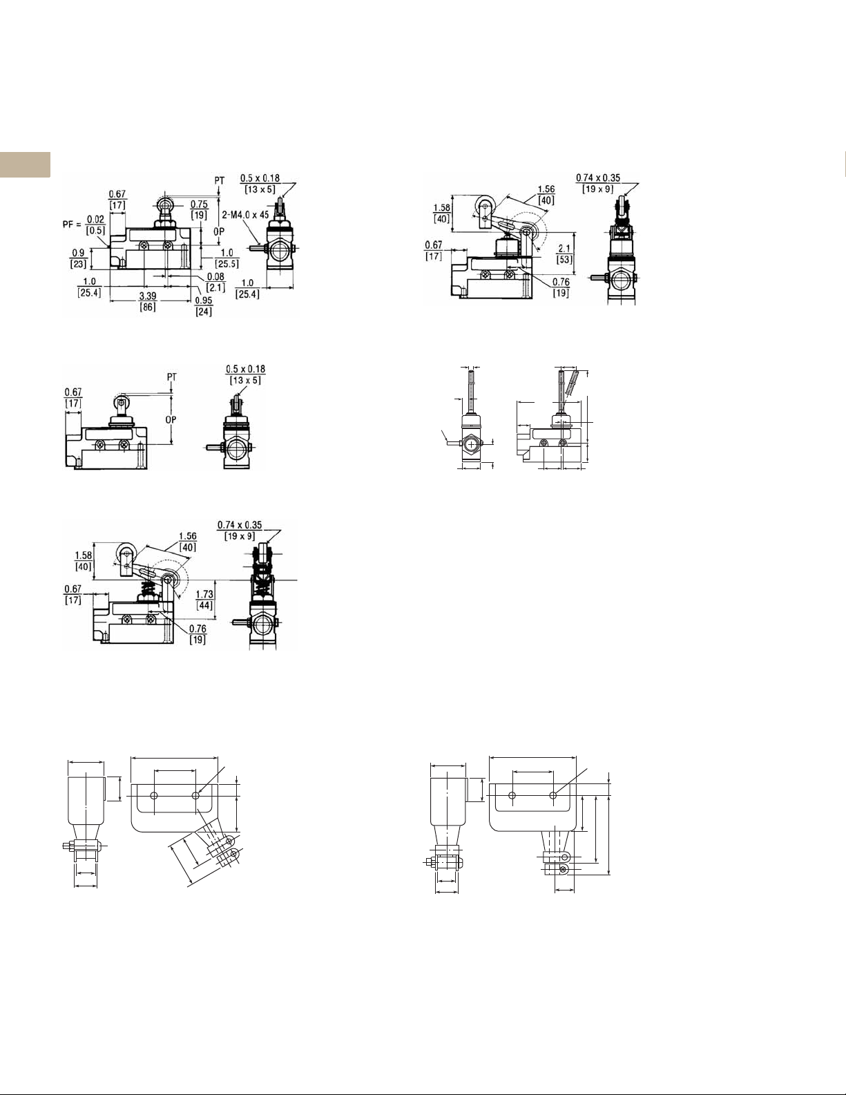
Compact Prewired Switches
2.2
Dimensions
Approximate Dimensions in mm [in]
E47BCC05
E47BCC06
E47BCC11
25.0
[0.984]
PT
OP
67.0
[2.638]
Max
51.5
[2.028]
2.0 [0.079]
34.0 [1.339]
E47BCC12
25.0
[0.984]
PT
OP
73.0
[2.874]
Max.
49.0
[1.929]
2.0
[0.079]
40.0 [1.575]
Max
40.0 [1.575]
34.0 [1.339]
2 x Ø5.1 [Ø0.201]
2 x Ø10.2 [0.402]
Depth: 6 [0.236]
7.0
[0.276]
7.5 [0.295]
8.0 [0.315]
23.0
2.0
[0.906]
[0.079]
2 x Ø5.1 [Ø0.201]
2 x Ø10.2 [0.402]
Depth: 6 [0.236]
Ø12.7 [0.500] x
4.0
[0.157]
Stainless Steel
7.5 [0.295]
8.0 [0.315]
23.0
2.0
[0.906]
[0.079]
Ø12.7 [0.500]
x 3.8 [0.150]
Stainless
Steel Roller
1.4
[0.055]
3.8 [0.150]
Roller
1.4
[0.055]
16.0
[0.630]
Max
2.8
[0.110]
Correct
Setting
Position
1.5
[0.059]
16.0
[0.630]
Max
Rubber
Cap
1.5
[0.059]
2
2
2
2
2
2
2
2
2
2
2
2
2
2
2
E47BCC07
E47BCC08
E47BCC13
25.0
[0.984]
OP
67.0
[2.638]
Max
51.5
[2.028]
2.0 [0.079]
34.0 [1.339]
PT
40.0 [1.575]
2 x Ø5.1 [Ø0.201]
2 x Ø10.2 [0.402]
Depth: 6 [0.236]
7.0
[0.276]
7.5 [0.295]
23.0
[0.906]
2.0
[0.079]
Ø10 [0.397]
Stainless
Steel PLU
8.0 [0.315]
[0.055]
1.4
16.0
[0.630]
2.8
[0.110]
Correct
Setting
Position
1.5
[0.059]
E47BCC15
Volume 8—Sensing Solutions CA08100010E—May 2013 V8-T2-19
2
2
2
2
2
2
2
2
2
2
2
2
2
2
2
2.2
40.0 [1.575]
49.0
[1.929]
2.0
[0.079]
1.4
[0.055]
1.5
[0.059]
16.0
[0.630]
Max
Rubber
Cap
34.0 [1.339]
2.0
[0.079]
23.0
[0.906]
8.0 [0.315]
7.5 [0.295]
4.0
[0.157]
2 x Ø10.2 [0.402]
Depth: 6 [0.236]
2 x Ø5.1 [Ø0.201]
103.7
[2.5]
25.0
[0.984]
50.7
Ø1.2
5.7
18 AWG/4
UL, SJT (0)
Ø8.5 [0.335]
159.0
[6.257]
16.0
[0.630]
1.5
[0.059]
1.3
[0.051]
Ø3.0
[0.117]
25.9
[1.020]
8.0
[0.315]
2.0
[0.079]
2.0 [0.079]
34.0 [1.339]
40.0 [1.575]
25.0
[0.984]
23.0
[0.906]
18 AWG/4
UL, SJT (0)
Ø8.5 [0.335]
Approximate Dimensions in mm [in]
2
E47BCC20
2
2
2
2
2
Limit Switches
Compact Prewired Switches
E47BCC22
25.0
[0.984]
Ø17.5
[0.69]
R 25.0–89.0
[0.984–3.600]
8.0
[0.315]
51.2 [2.017]
7.0 [0.280]
16.0
[0.630]
2
2
2
2
2
2
2
2
2
2
2
2
2
2
E47BCC21
23.0
[0.906]
18 AWG/4
UL, SJT (0)
Ø 8.5 [0.335]
2.0
[0.079]
2.0 [0.079]
34.0 [1.339]
40.0 [1.575]
1.3
[0.051]
18 AWG/4
UL, SJT (0)
Ø 8.5 [0.335]
1.5
[0.059]
2
2
2
2
2
2
2
2
2
2
V8-T2-20 Volume 8—Sensing Solutions CA08100010E—May 2013
Limit Switches
LS-Titan Miniature DIN Switches
LS-Titan Miniature DIN Switches
2.3
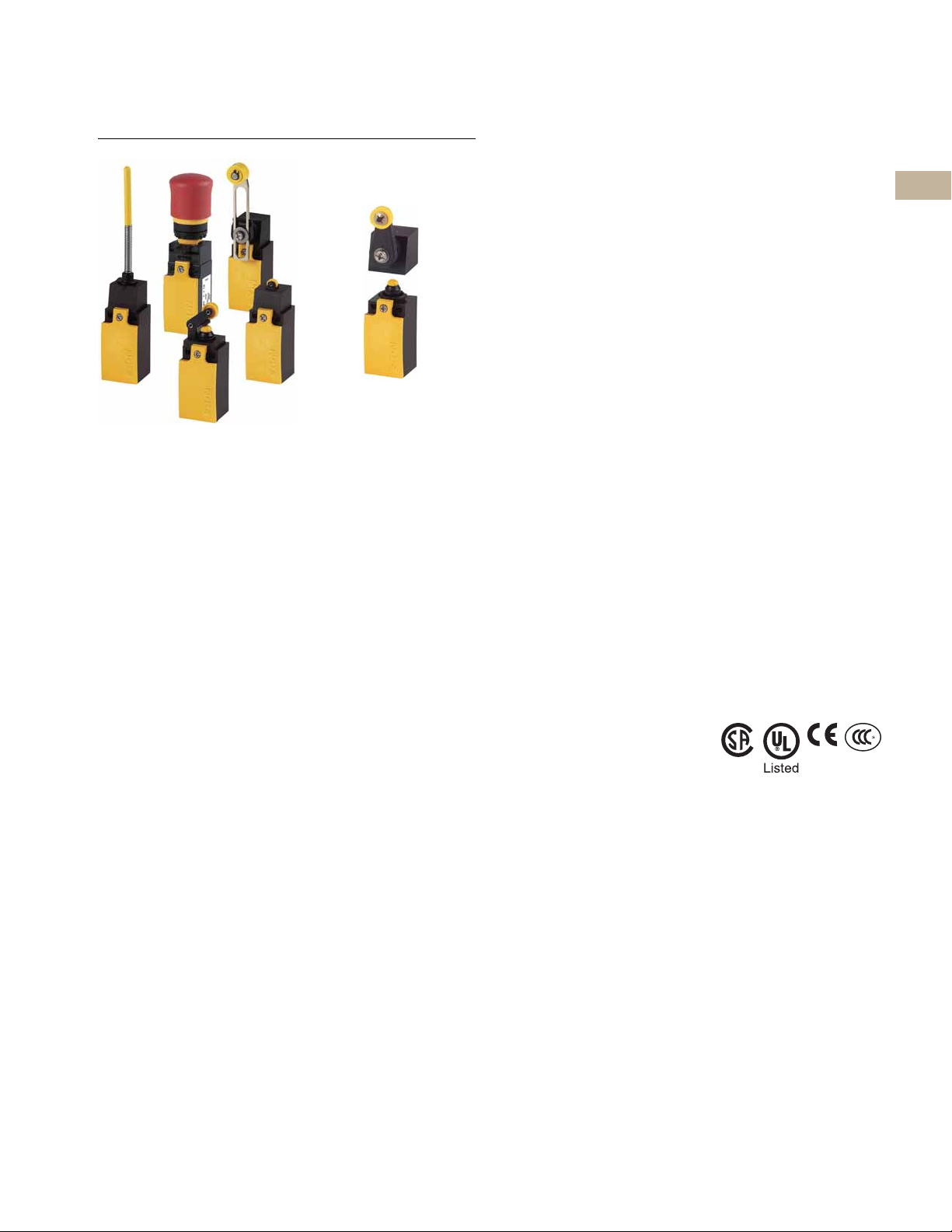
LS-Titan Miniature DIN Switches
Product Description
Eaton’s LS-Titan™ limit
switch line is a complete
offering of safety position
switches designed for
worldwide application.
Economical insulated
plastic or rugged metal
enclosures and modular,
plug-in operating heads
and bodies make LS-Titan a
flexible switching solution.
A highlight of the LS-Titan
switch line is the world’s
first electronic position
switch (LSE models). These
switches feature freely
programmable operating
points that can be set
individually at any time.
Additional LSE models
provide analog outputs
proportional to the
actuator position.
LS-Titan switches are suitable
for use in safety applications
designed to protect persons
or processes.
Features
●
Modular, plug-in
stem (head a
sy
bo
dy components)
●
Positive opening NC
ntacts for safet
co
ap
plications
●
Wide variety of economical
plastic and rugged metal
versions available
●
Operating heads can
rotated 90 degrees
be
to suit specific directio
of operation
●
Unique electronic safety
sition switches (L
po
mod
els) provide anal
(0–10 Vdc or 4–20 mA)
tputs proportional
ou
act
uator position and allo
for easy configuration of
custom trip poin
a
nd
y
SE
to the
t
og
Contents
Description Page
LS-Titan Miniature DIN Switches
Product Identification . . . . . . . . . . . . . . . . . . . . V8-T2-22
Product Selection . . . . . . . . . . . . . . . . . . . . . . . V8-T2-23
LS-Titan Plastic Safety Switches . . . . . . . . . V8-T2-23
LS-Titan Plastic Electronic
Safety Position Switches . . . . . . . . . . . . . V8-T2-26
LS-Titan Metal Safety Switches . . . . . . . . . V8-T2-30
Understanding LS-Titan Electronic
Safety Position Switches . . . . . . . . . . . . . V8-T2-32
Operating Point Adjustment . . . . . . . . . . . . V8-T2-32
Accessories . . . . . . . . . . . . . . . . . . . . . . . . . . . V8-T2-33
Technical Data and Specifications . . . . . . . . . . V8-T2-34
Contact Travel Diagrams . . . . . . . . . . . . . . . . . . V8-T2-37
Dimensions . . . . . . . . . . . . . . . . . . . . . . . . . . . V8-T2-40
2
2
2
2
2
2
2
2
2
2
2
Standards and Certifications
●
Can be ordered as
arate compon
sep
(
head and body) or as
completely assembled
tches
swi
●
Screw and Cage Clamp
standard on LSE mode
(
and
optionally availabl
on mechanical models)
nections provide larg
con
wi
ring areas for easi
n
installation
●
Approved for worldwide
lication
app
ents
®
ls
e
er
●
Safety function by positive
opening contacts pe
I
EC/EN 60947-5-1 up
Category 4 per EN 954-1
●
TÜV-Rheinland Certified
or Functional-Safet
f
(L
SE models)
●
CSA certified
●
er
UL listed
●
CE
●
CCC
r
to
y
2
2
2
2
2
2
2
2
Note: Cage Clamp is a
w
registered trademark of
Wago Kontakttechnik,
32423 Minden, Germany.
2
2
2
2
2
2
Volume 8—Sensing Solutions CA08100010E—May 2013 V8-T2-21
2
2
2
2
2
2.3
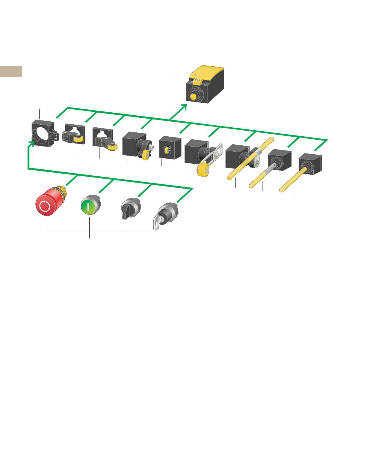
Product Identification
2
Limit Switches
LS-Titan Miniature DIN Switches
2
2
2
2
2
2
2
2
2
2
2
2
2
2
1
2
3
4
k
5
6
7
8
9
j
2
2
2
2
2
2
2
2
2
2
2
2
2
2
Notes
1
Basic device
(see Pages V8-T2-23 to V8-T2-31)
According to EN 50047
With screw-on cover
Contacts: 1NO-1NC, 2NO, 2NC
Cage Clamp, screw terminal
As snap-action or standard-action switch
As electronic snap-action switch
(individually adjustable)
As 4–20 mA analog signal encoder
As 0–10 Vdc analog signal encoder
2
Fixing adapter (see Page V8-T2-33)
Allows mounting of M22 pushbuttons
3
Roller lever
(see Pages V8-T2-23 and V8-T2-26)
For one-sided operation with higher
operating speed
4
Angled roller lever
(see Pages V8-T2-23, V8-T2-26 and
V8-T2-30)
For actuation along the unit axis
5
Rotary lever (see Pages V8-T2-23,
V8-T2-27 and V8-T2-30)
For actuation from the side, for
pendulum movements
6
Roller plunger (see Pages V8-T2-23,
V8-T2-26 and V8-T2-30)
For actuation from the side with low
actuating force
7
Adjustable roller lever
(see Pages V8-T2-24, V8-T2-27,
V8-T2-28 and V8-T2-30)
For length adjustment as required
8
Actuating rod (see Pages V8-T2-25,
V8-T2-29 and V8-T2-31)
On conveyor belts for lightweight goods
9
Spring-rod (see Pages V8-T2-25,
V8-T2-29 and V8-T2-31)
For flexible actuation from all sides
j Actuating rod (see Pages V8-T2-25,
V8-T2-29 and V8-T2-31)
Withdrawable mechanism from front
k Pushbuttons from the M22 family; see
M22 catalog (CA04716001E) or
Operating heads can be rotated
by 90 degrees.
m22
2
V8-T2-22 Volume 8—Sensing Solutions CA08100010E—May 2013
Limit Switches
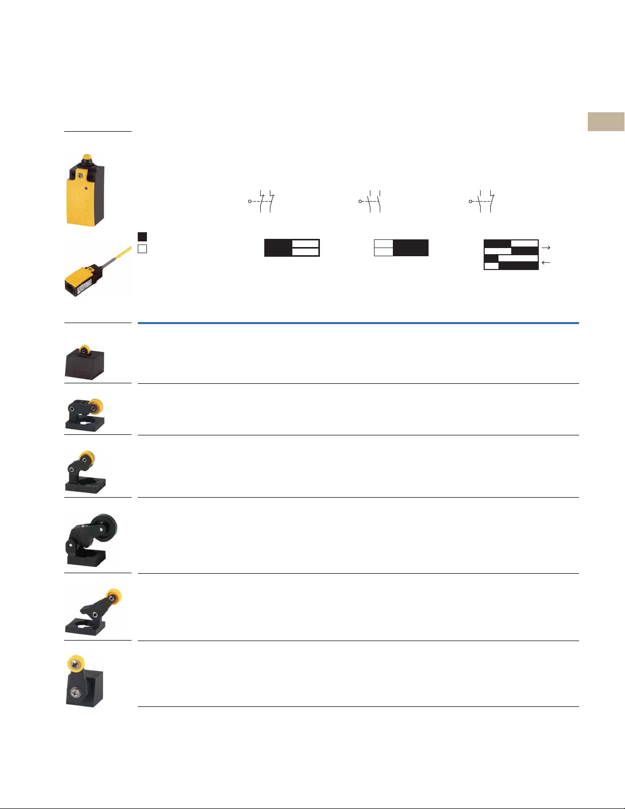
Plastic Safety
Switch Body
Top Push Roller
Plunger
Long Roller Lever
Short Roller Lever
Large Roller Lever
Angled Roller
Assembled Switch
Rotary Lever
13
14 24
23
NC
11–12
21–22
NC
Zw = 4.5 mm
3.0
0 3.0 6.1
13–14
13–14
21–22
21–22
Zw = 5.5 mm
1.6
0
3.0
6.1
LS-Titan Miniature DIN Switches
2.3
Product Selection
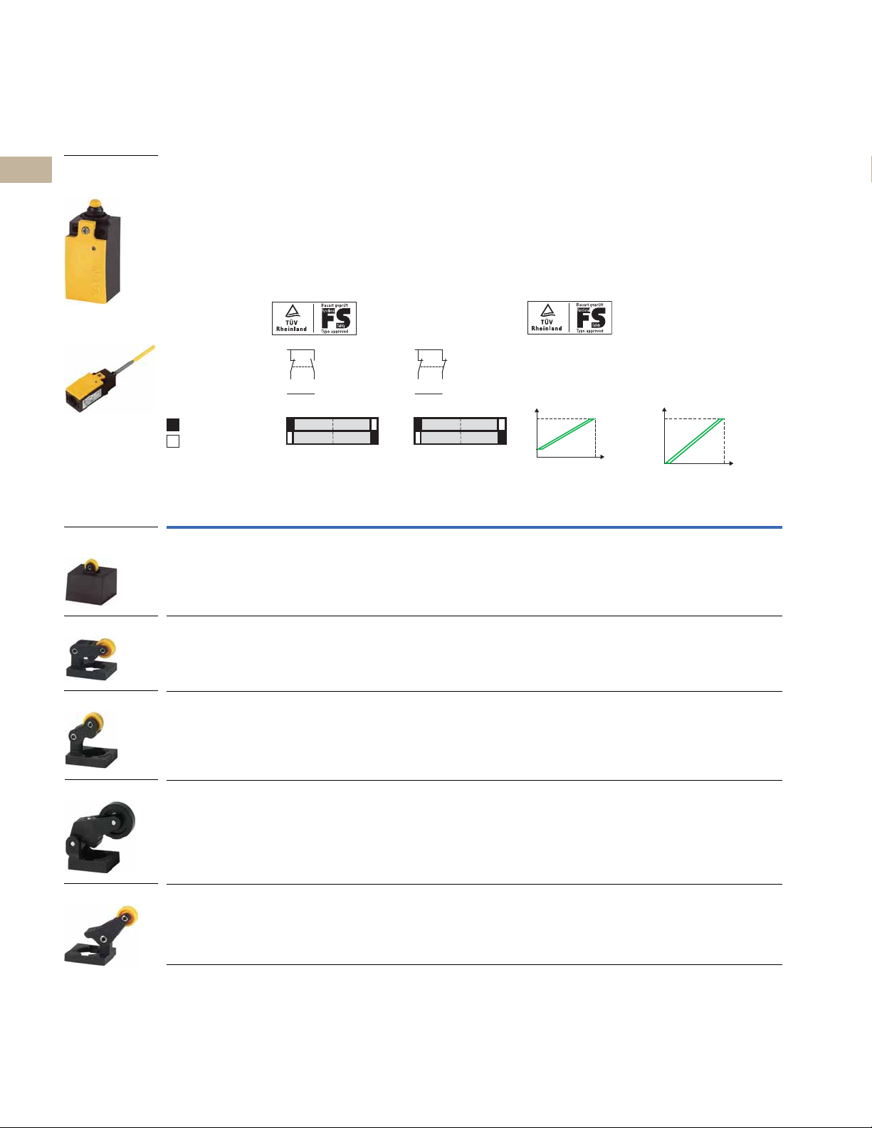
LS-Titan Plastic Safety Switches
Plastic Safety Switches
Switch Body Catalog Number LS-S02 LS-S20A LS-S11S
Output Function 2NC with positive
Terminal Connection Screw terminal
Contact Sequence
Contact Travel Snap-action contact
= contact closed
= contact open
Operating Head Type
Head Only
Catalog Number
LS-XP LS-S02-P LS-S20A-P LS-S11S-P
LS-XL LS-S02-L LS-S20A-L LS-S11S-L
2
2
2
opening contacts
11
21
12
22
2NO with slow
make/break
1
Screw terminal
13–14
23–24
1
0 2.1 6.1
2.1
ZW = 4.5 mm
NO
NO
1NO and 1NC with
positive opening contact
Screw terminal
1
21
13
14
22
2
2
2
2
2
2
2
Assembled Switch
Catalog Number
2
2
2
2
2
2
LS-XLS LS-S02-LS LS-S20A-LS LS-S11S-LS
LS-XLB LS-S02-LB LS-S20A-LB LS-S11S-LB
LS-XLA LS-S02-LA LS-S20A-LA LS-S11S-LA
LS-XRL LS-S02-RL LS-S20A-RL LS-S11S-RL
Notes
1
Cage Clamp versions available. Contact Application Engineering.
2
For operating head dimensions, see Page V8-T2-40.
2
2
2
2
2
2
2
2
2
2
2
2
2
2
2
Volume 8—Sensing Solutions CA08100010E—May 2013 V8-T2-23
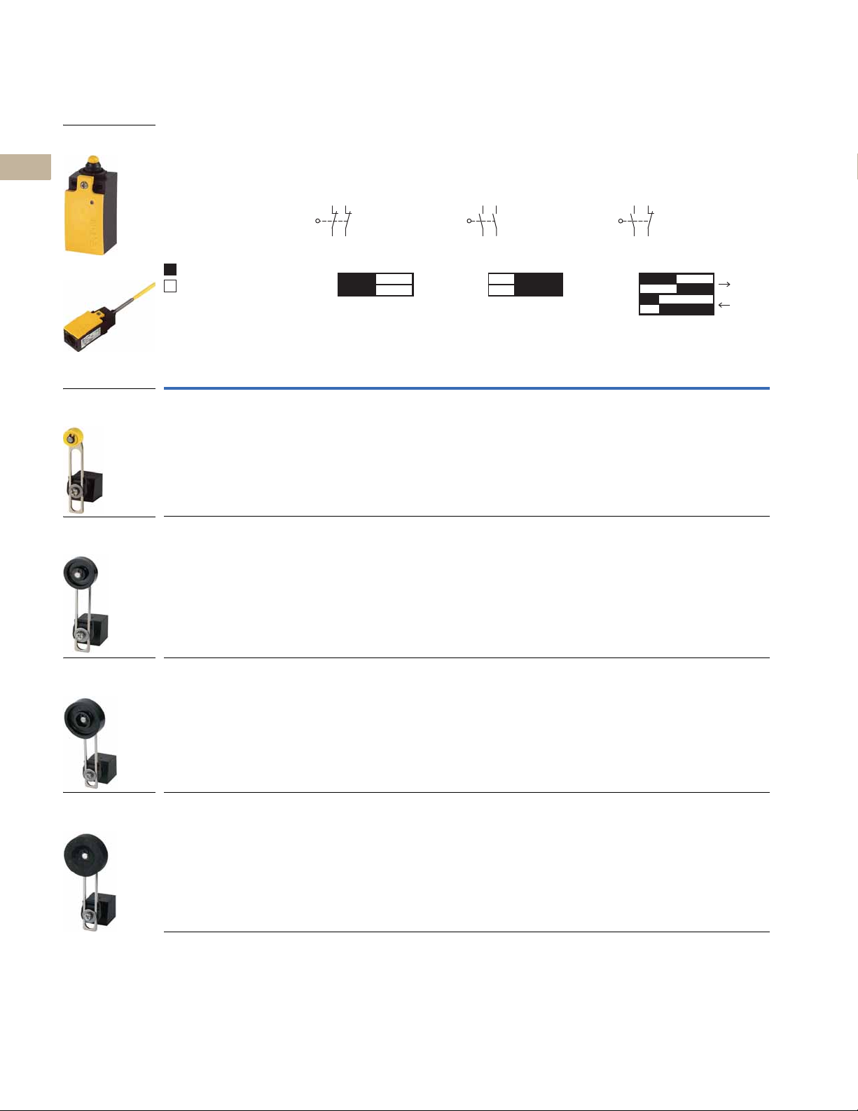
2.3
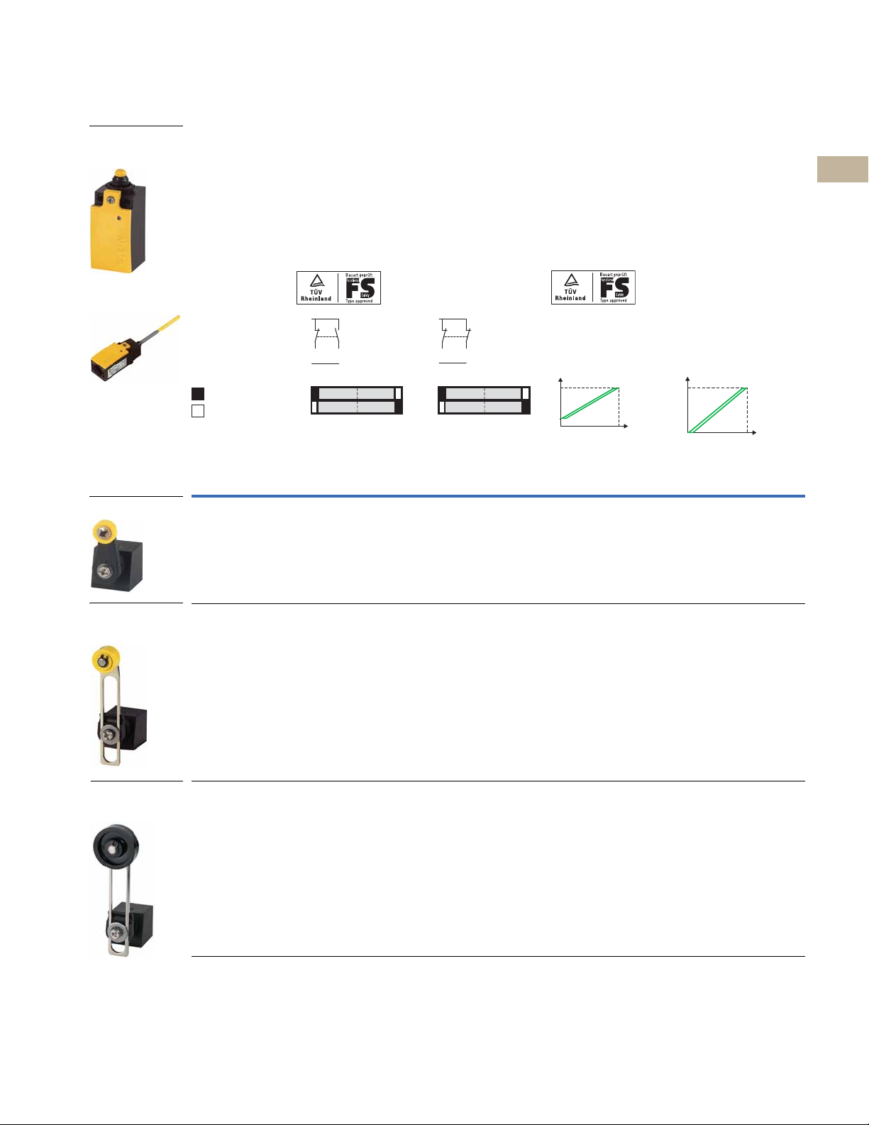
Adjustable
Roller Lever
(with 18 mm Roller)
Adjustable
Roller Lever
(with 30 mm Roller)
Adjustable
Roller Lever
(with 40 mm Roller)
Adjustable Roller
Lever (with 40 mm
Rubber Roller)
Plastic Safety
Switch Body
Assembled Switch
13
14 24
23
= contact closed
= contact open
NC
11–12
21–22
NC
Zw = 4.5 mm
3.0
0 3.0 6.1
13–14
13–14
21–22
21–22
Zw = 5.5 mm
1.6
0
3.0
6.1
Limit Switches
LS-Titan Miniature DIN Switches
2
2
2
2
2
2
2
2
2
2
2
2
2
2
2
Plastic Safety Switches, continued
Switch Body Catalog Number LS-S02 LS-S20A LS-S11S
Output Function 2NC with positive
Terminal Connection Screw terminal
Contact Sequence
Contact Travel Snap-action contact
Operating Head Type
Head Only
Catalog Number
LS-XRLA LS-S02-RLA LS-S20A-RLA LS-S11S-RLA
LS-XRLA30 LS-S02-RLA30 LS-S20A-RLA30 LS-S11S-RLA30
2
opening contacts
1
2111
12
22
Assembled Switch
Catalog Number
2NO with slow
make/break
Screw terminal
0 2.1 6.1
13–14
23–24
2.1
ZW = 4.5 mm
1NO and 1NC with
positive opening contact
1
NO
NO
Screw terminal
1
21
13
14
22
2
2
2
2
2
2
2
2
2
2
2
2
2
2
LS-XRLA40 LS-S02-RLA40 LS-S20A-RLA40 LS-S11S-RLA40
LS-XRLA40R LS-S02-RLA40R LS-S20A-RLA40R LS-S11S-RLA40R
Notes
1
Cage Clamp versions available. Contact Application Engineering.
2
For operating head dimensions, see Page V8-T2-40.
2
V8-T2-24 Volume 8—Sensing Solutions CA08100010E—May 2013
Limit Switches
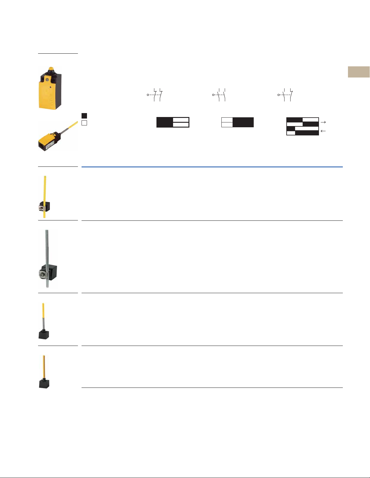
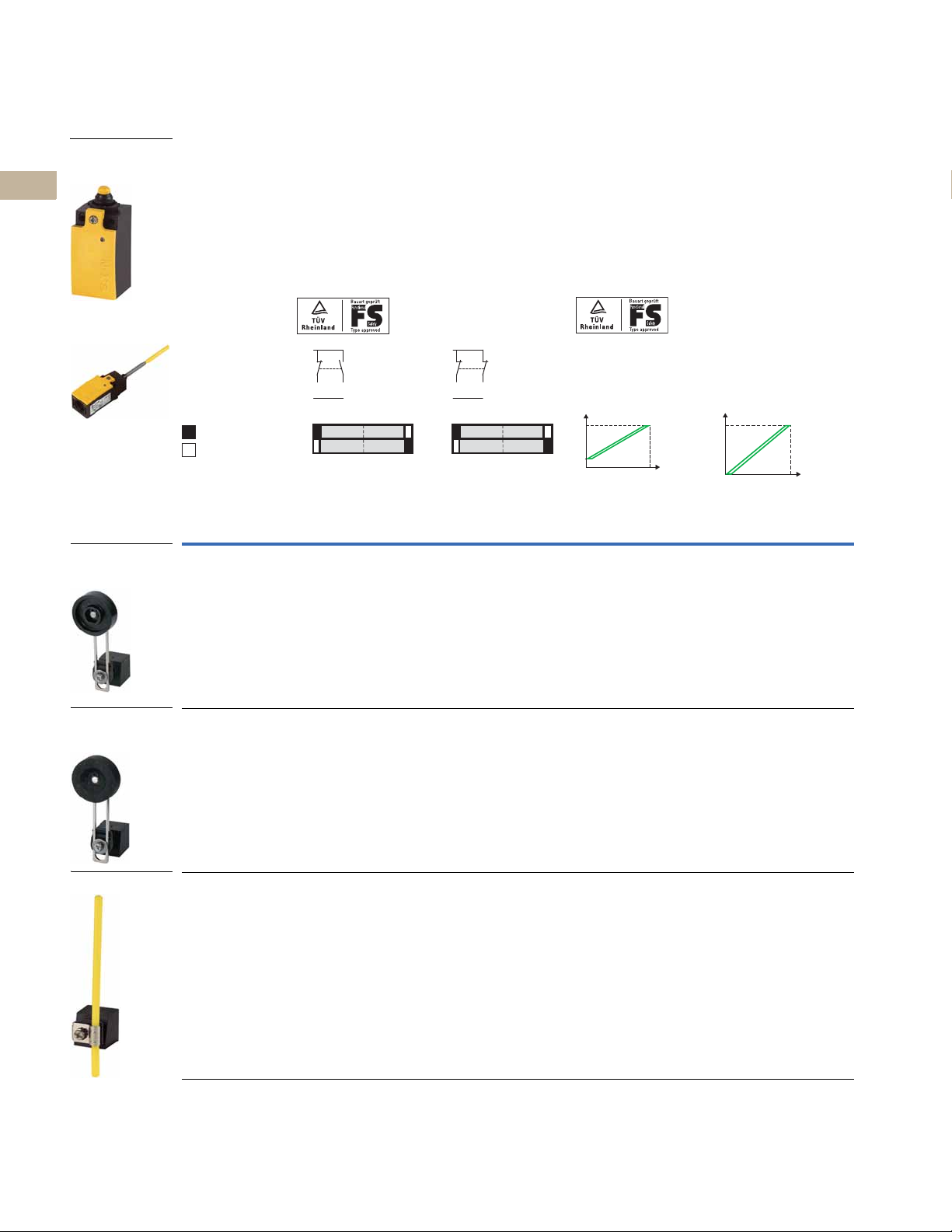
Plastic Rod Lever
Metal Rod
Spring Rod (Wobble)
3
Actuating Rod
Plastic Safety
Switch Body
Assembled Switch
13
14 24
23
NC
11–12
21–22
NC
Zw = 4.5 mm
3.0
0 3.0 6.1
13–14
13–14
21–22
21–22
Zw = 5.5 mm
1.6
0
3.0
6.1
LS-Titan Miniature DIN Switches
2.3
Plastic Safety Switches, continued
Switch Body Catalog Number LS-S02 LS-S20A LS-S11S
Output Function 2NC with positive
Terminal Connection Screw terminal
Contact Sequence
Contact Travel Snap-action contact
= contact closed
= contact open
Operating Head Type
Head Only
Catalog Number
LS-XRR LS-S02-RR LS-S20A-RR LS-S11S-RR
LS-XRRM LS-S02-RRM LS-S20A-RRM LS-S11S-RRM
2
opening contacts
1
2111
12
22
Assembled Switch
Catalog Number
2NO with slow
make/break
Screw terminal
0 2.1 6.1
13–14
23–24
2.1
ZW = 4.5 mm
1NO and 1NC with
positive opening contact
1
NO
NO
Screw terminal
1
21
13
14
22
2
2
2
2
2
2
2
2
2
2
2
2
2
2
2
2
2
2
LS-XS LS-S02-S LS-S20A-S LS-S11S-S
2
2
2
2
LS-XOR LS-S02-OR LS-S20A-OR LS-S11S-OR
2
2
2
2
Notes
1
Cage Clamp versions available. Contact Application Engineering.
2
For operating head dimensions, see Page V8-T2-40.
3
Not to be used as a safety position switch. Use only in conjunction with snap-action contact.
2
2
2
2
Volume 8—Sensing Solutions CA08100010E—May 2013 V8-T2-25
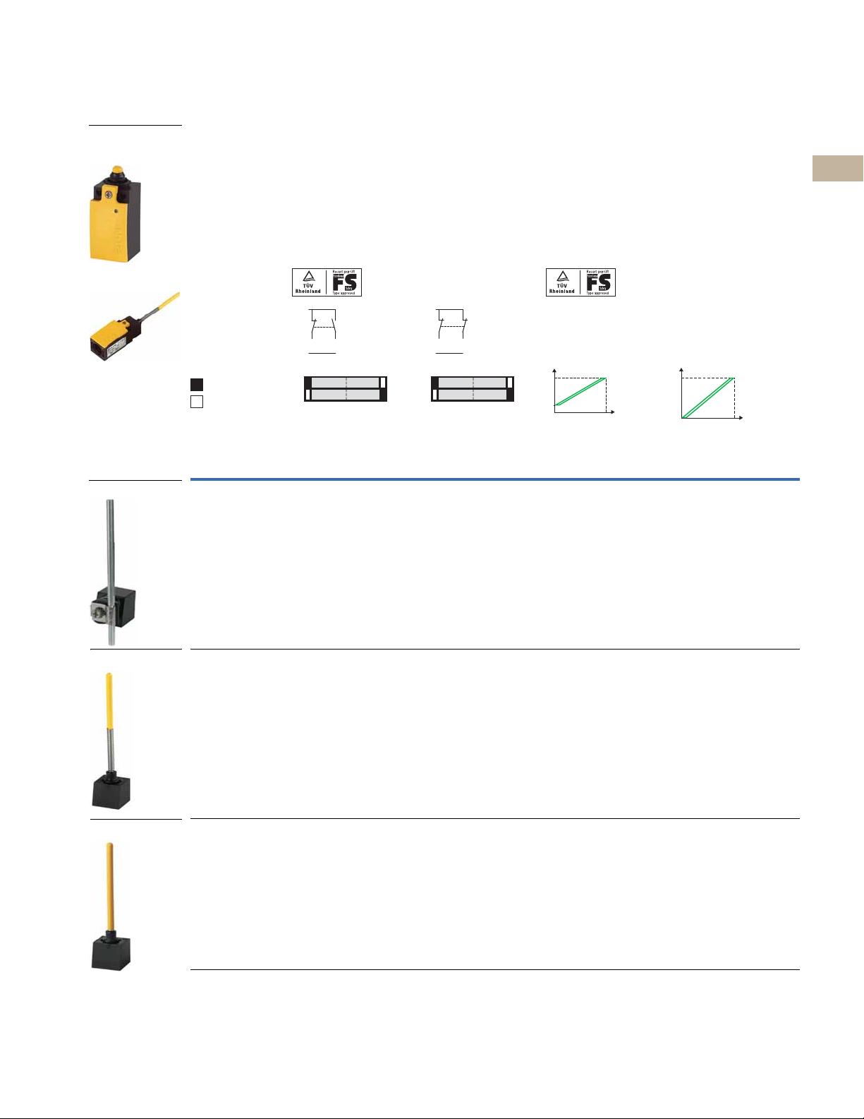
2.3
Plastic Electronic
Safety Position
Switch Body
Top Push Roller
Plunger
Long Roller Lever
Short Roller Lever
Large Roller Lever
Assembled Switch
Angled Roller
Q10VQ2
+U
e
electron.
= contact closed
= contact open
Q1
Q2
0.5 5.5
default=3.0
6.1
0
LS-Titan Plastic Electronic Safety Position Switches
2
2
2
2
2
2
2
2
2
2
2
2
2
2
Limit Switches
LS-Titan Miniature DIN Switches
Plastic Electronic Safety Position Switches
Switch Body
Catalog Number LSE-11 LSE-02 LSE-AI LSE-AU
Output Function 1NO and 1 NC 2NC Analog 4–20 mA Analog 0–10V
Terminal Connections Cage Clamp
Safety Functions
and Approvals
Contact Sequence Analog 4–20 mA Analog 0–10V
Contact Travel
Operating Head Type
Head Only
Catalog Number
LS-XP LSE-11-P LSE-02-P LSE-AI-P LSE-AU-P
These models may be used in safety-oriented circuits. Visual status
LED indication is comparable to positive opening contacts. Certified
by TÜV as a “Functional-Safety” device. Suitable for protection of
people or processes.
2
Assembled Switch
Catalog Number
1
Cage Clamp
+U
Q1
Q2
1
e
electron.
Q10VQ2
0
0.5 5.5
default=3.0
4
0
I [mA]
1
S [%]
100
Cage Clamp
U [V]
10
0100
Cage Clamp
Additional diagnostic output that registers a 0V signal in the event
of a fault. Self-test function continuously tests both outputs for
overloads, short circuits to 0V and short circuits to +U
TÜV to EN 954-1, Category 3 or 4. Suitable for protection of people
or processes.
6.1
20
1
. Certified by
e
S [%]
2
2
2
2
2
2
2
2
2
2
2
2
2
2
2
LS-XL LSE-11-L LSE-02-L LSE-AI-L LSE-AU-L
LS-XLS LSE-11-LS LSE-02-LS LSE-AI-LS LSE-AU-LS
LS-XLB LSE-11-LB LSE-02-LB LSE-AI-LB LSE-AU-LB
LS-XLA LSE-11-LA LSE-02-LA LSE-AI-LA LSE-AU-LA
Notes
1
A compatible Cage Clamp tool is available as an accessory on Page V8-T2-33.
2
For operating head dimensions, see Page V8-T2-40.
2
V8-T2-26 Volume 8—Sensing Solutions CA08100010E—May 2013
Limit Switches
Rotary Lever
Adjustable
Roller Lever
(with 18 mm Roller)
Adjustable
Roller Lever
(With 30 mm Roller)
Plastic Electronic
Safety Position
Switch Body
Assembled Switch
Q10VQ2
+U
e
electron.
Q1
Q2
0.5 5.5
default=3.0
6.1
0
LS-Titan Miniature DIN Switches
2.3
Plastic Electronic Safety Position Switches, continued
Switch Body
Catalog Number LSE-11 LSE-02 LSE-AI LSE-AU
Output Function 1NO and 1NC 2NC Analog 4–20 mA Analog 0–10V
Terminal Connections Cage Clamp
Safety Functions
and Approvals
Contact Sequence Analog 4–20 mA Analog 0–10V
Contact Travel
= contact closed
= contact open
Operating Head Type
Head Only
Catalog Number
LS-XRL LSE-11-RL LSE-02-RL LSE-AI-RL LSE-AU-RL
These models may be used in safety-oriented circuits. Visual status
LED indication is comparable to positive opening contacts. Certified
by TÜV as a “Functional-Safety” device. Suitable for protection of
people or processes.
2
Assembled Switch
Catalog Number
1
Cage Clamp
+U
Q1
Q2
1
e
electron.
Q10VQ2
0
0.5 5.5
default=3.0
4
0
I [mA]
1
S [%]
100
Cage Clamp
U [V]
10
0100
Cage Clamp
Additional diagnostic output that registers a 0V signal in the event
of a fault. Self-test function continuously tests both outputs for
overloads, short circuits to 0V and short circuits to +U
TÜV to EN 954-1, Category 3 or 4. Suitable for protection of people
or processes.
6.1
20
1
. Certified by
e
S [%]
2
2
2
2
2
2
2
2
2
2
2
2
2
2
LS-XRLA LSE-11-RLA LSE-02-RLA LSE-AI-RLA LSE-AU-RLA
LS-XRLA30 LSE-11-RLA30 LSE-02-RLA30 LSE-AI-RLA30 LSE-AU-RLA30
Notes
1
A compatible Cage Clamp tool is available as an accessory on Page V8-T2-33.
2
For operating head dimensions, see Page V8-T2-40.
2
2
2
2
2
2
2
2
2
2
2
2
2
2
2
2
Volume 8—Sensing Solutions CA08100010E—May 2013 V8-T2-27
2.3
Plastic Rod Lever
Adjustable
Roller Lever
(With 40 mm Roller)
Adjustable
Roller Lever
(With 40 mm Roller)
Plastic Electronic
Safety Position
Switch Body
Assembled Switch
Q10VQ2
+U
e
electron.
= contact closed
= contact open
Q1
Q2
0.5 5.5
default=3.0
6.1
0
Limit Switches
LS-Titan Miniature DIN Switches
2
2
2
2
2
2
2
2
2
2
2
2
2
2
Plastic Electronic Safety Position Switches, continued
Switch Body
Catalog Number LSE-11 LSE-02 LSE-AI LSE-AU
Output Function 1NO and 1NC 2NC Analog 4–20 mA Analog 0–10V
Terminal Connections Cage Clamp
Safety Functions
and Approvals
Contact Sequence Analog 4–20 mA Analog 0–10V
Contact Travel
Operating Head Type
Head Only
Catalog Number
LS-XRLA40 LSE-11-RLA40 LSE-02-RLA40 LSE-AI-RLA40 LSE-AU-RLA40
These models may be used in safety-oriented circuits. Visual status
LED indication is comparable to positive opening contacts. Certified
by TÜV as a “Functional-Safety” device. Suitable for protection of
people or processes.
2
Assembled Switch
Catalog Number
1
Cage Clamp
+U
Q1
Q2
1
e
electron.
Q10VQ2
0
0.5 5.5
default=3.0
4
0
I [mA]
1
S [%]
100
Cage Clamp
10
Cage Clamp
Additional diagnostic output that registers a 0V signal in the event
of a fault. Self-test function continuously tests both outputs for
overloads, short circuits to 0V and short circuits to +U
TÜV to EN 954-1, Category 3 or 4. Suitable for protection of people
or processes.
6.1
20
1
U [V]
0100
. Certified by
e
S [%]
2
2
2
2
2
2
2
2
2
2
2
2
2
2
LS-XRLA40R LSE-11-RLA40R LSE-02-RLA40R LSE-AI-RLA40R LSE-AU-RLA40R
LS-XRR LSE-11-RR LSE-02-RR LSE-AI-RR LSE-AU-RR
2
2
Notes
1
A compatible Cage Clamp tool is available as an accessory on Page V8-T2-33.
2
For operating head dimensions, see Page V8-T2-40.
V8-T2-28 Volume 8—Sensing Solutions CA08100010E—May 2013
Limit Switches
Plastic Electronic
Safety Position
Switch Body
Spring Rod (Wobble)
3
Actuating Rod
Assembled Switch
Metal Rod
Q10VQ2
+U
e
electron.
Q10VQ2
+U
e
electron.
I [mA]
20
0
4
100
S [%]
10
0100
S [%]
U [V]
LS-Titan Miniature DIN Switches
2.3
Plastic Electronic Safety Position Switches, continued
Switch Body
Catalog Number LSE-11 LSE-02 LSE-AI LSE-AU
Output Function 1NO and 1NC 2NC Analog 4–20 mA Analog 0–10V
Terminal Connections Cage Clamp
Safety Functions
and Approvals
Contact Sequence Analog 4–20 mA Analog 0–10V
Contact Travel
= contact closed
= contact open
Operating Head Type
Head Only
Catalog Number
LS-XRRM LSE-11-RRM LSE-02-RRM LSE-AI-RRM LSE-AU-RRM
These models may be used in safety-oriented circuits. Visual status
LED indication is comparable to positive opening contacts. Certified
by TÜV as a “Functional-Safety” device. Suitable for protection of
people or processes.
Q1
Q2
2
Assembled Switch
Catalog Number
1
0
0.5 5.5
default=3.0
Cage Clamp
6.1
Q1
Q2
1
0
0.5 5.5
default=3.0
Cage Clamp
Additional diagnostic output that registers a 0V signal in the event
of a fault. Self-test function continuously tests both outputs for
overloads, short circuits to 0V and short circuits to +U
by TÜV to EN 954-1, Category 3 or 4. Suitable for protection of people
or processes.
6.1
1
Cage Clamp
1
. Certified
e
2
2
2
2
2
2
2
2
2
2
2
2
2
2
2
2
2
LS-XS LSE-11-S LSE-02-S LSE-AI-S LSE-AU-S
2
2
2
2
2
2
LS-XOR LSE-11-OR LSE-02-OR LSE-AI-OR LSE-AU-OR
2
2
2
2
2
Notes
1
A compatible Cage Clamp tool is available as an accessory on Page V8-T2-33.
2
For operating head dimensions, see Page V8-T2-40.
3
Not to be used as a safety position switch. Use only in conjunction with snap-action contact.
2
2
Volume 8—Sensing Solutions CA08100010E—May 2013 V8-T2-29
2.3
Top Push Roller
Plunger
Long Roller Lever
Angled Roller
Rotary Lever
Adjustable Roller Lever
Metal Safety
Switch Body
Assembled Switch
12
22
2111
= contact closed
= contact open
NC
11–12
21–22
NC
Zw = 4.5 mm
3.0
0 3.0 6.1
13–14
13–14
21–22
21–22
Zw = 5.5 mm
1.6
0
3.0
6.1
LS-Titan Metal Safety Switches
2
2
2
2
Limit Switches
LS-Titan Miniature DIN Switches
Metal Safety Switches
Switch Body Catalog Number LSM-02 LSM-20A LSM-11S
Output Function 2NC with positive
opening contacts
Terminal Connection Cage Clamp Cage Clamp Cage Clamp
Contact Sequence
2NO with slow
make/break
13
23
1NO and 1NC with
positive opening contact
13
21
2
2
2
2
2
2
2
2
2
2
2
2
2
2
14 24
Contact Travel Snap-action contact
Operating Head Type
Head Only
Catalog Number
LSM-XP LSM-02-P LSM-20A-P LSM-11S-P
LSM-XL LSM-02-L LSM-20A-L LSM-11S-L
LSM-XLA LSM-02-LA LSM-20A-LA LSM-11S-LA
1
Assembled Switch
Catalog Number
0 2.1 6.1
13–14
23–24
2.1
ZW = 4.5 mm
NO
NO
14
22
2
2
2
2
2
2
2
2
2
2
2
2
V8-T2-30 Volume 8—Sensing Solutions CA08100010E—May 2013
LSM-XRL LSM-02-RL LSM-20A-RL LSM-11S-RL
LSM-XRLA LSM-02-RLA LSM-20A-RLA LSM-11S-RLA
Note
1
For operating head dimensions, see Page V8-T2-40.
 Loading...