

User’s manual
LUFP9
Telemecanique
Gateway
DeviceNet / Modbus RTU


LUFP9
Gateway DeviceNet / Modbus RTU Page 4
3

In spite of all the care taken over the writing of this document, Schneider Electric SA does not give
any guarantees in relation to the information contained in it, and may not be held liable for any
errors, nor for any damage which might result from its use or its application.
The characteristics and operation of the products and additives presented in this document may
change at any time. The description is in no way contractually binding.
4

Table of contents
1. Introduction............................................................6
1.1. Introduction to the user guide................................................. 6
1.2. Introduction to the LUFP9 Gateway ....................................... 7
1.3. Terminology............................................................................ 7
1.4. Notational Conventions .......................................................... 8
1.5. Additional Documentation ......................................................8
1.6. Introduction to the Communication “System” Architecture ..... 9
1.7. Principle Used to Configure and Operate the LUFP9 Gateway 10
2. Hardware Implementation of the LUFP9
Gateway ........................................................... 13
2.1. On Receipt ...........................................................................13
2.2. Introduction to the LUFP9 Gateway ..................................... 13
2.3. Mounting the Gateway on a DIN Rail ................................... 14
2.4. Powering the gateway .......................................................... 14
2.5. Connecting the Gateway to the Modbus Network ................ 15
2.5.1. Examples of Modbus connection topologies.................. 15
2.5.2. Pin outs .......................................................................... 17
2.5.3. Wiring recommendations for the Modbus network......... 18
2.6. Connecting the LUFP9 gateway to the DeviceNet network .19
2.7. Configuring DeviceNet Communication Features ................ 20
2.7.1. Encoding DeviceNet Speed ........................................... 20
2.7.2. Encoding the Gateway Address..................................... 21
2.7.3. Sample Gateway Configurations.................................... 21
6.8.1. Replacing a Periodic Input Data Element.......................48
6.8.2. Replacing an Output Periodic Data Element ..................49
6.8.3. Increasing the Amount of Periodic Input Data ................50
6.8.4. Increasing the amount of periodic output data ...............53
6.9. Deleting Aperiodic Parameter Data ......................................58
6.10. Changing a Modbus slave Configuration............................60
6.10.1. Changing the Name of a Modbus Slave.......................60
6.10.2. Changing the Address of a Modbus Slave ...................61
6.11. Adding and Setting Up a Modbus Command .....................62
6.11.1. With TeSys U Motor Starters........................................62
6.11.2. With a Generic Modbus Slave ......................................63
6.11.2.1. Managing Degraded Modes ...................................65
6.11.2.2. Configuring the Query ............................................66
6.11.2.3. Configuring the Response......................................69
6.11.2.4. Configuring the Content of the Query Frame .........70
6.11.2.5. Configuring the Content of the Response Frame...72
6.11.3. Adding a Special Modbus Command ...........................73
6.11.3.1. Modbus Commands Based on Standard Commands
...............................................................................73
6.11.3.2. Modbus Commands which Can Be Completely
Changed by the User.............................................74
6.12. Configuring the General Characteristics of the Gateway....75
6.12.1. “Fieldbus” element........................................................75
6.12.2. “ABC” Element..............................................................76
6.12.3. “Sub-Network” Element ................................................77
6.13. Adding a Broadcaster Node................................................79
3. Signalling ............................................................ 22
7. Appendix A: Technical Characteristics............ 80
4. Software Implementation of the Gateway........ 23
4.1. Introduction........................................................................... 23
4.1.1. System Architecture ....................................................... 23
4.1.2. Configuring the Motor Starters ....................................... 24
4.1.3. Modbus cycle time .........................................................24
4.1.4. Managing degraded modes ...........................................24
4.2. Configuring the Gateway in RsNetWorx............................... 25
4.2.1. Selecting and adding the master PLC’s DeviceNet
scanner........................................................................... 25
4.2.2. Installing the Gateway Description File.......................... 25
4.2.3. Selecting and Adding the Gateway to the DeviceNet
Network ..........................................................................26
4.2.4. Editing gateway parameters........................................... 26
4.2.5. Configuring the DeviceNet Scanner............................... 28
4.2.6. Configuring Inputs from the Gateway............................. 29
4.2.7. Configuring Outputs Intended for the Gateway.............. 30
4.2.8. Description of Services Assigned to Gateway
Inputs/Outputs ................................................................ 31
4.2.9. Transferring the DeviceNet Scanner Configuration .......32
4.2.10. Developing a DeviceNet Application............................ 32
5. Gateway Initialization and Diagnostics............ 33
5.1. Full Management.................................................................. 33
5.1.1. DeviceNet Master Command Word ...............................33
5.1.2. Gateway Status Word ....................................................35
5.2. Diagnostic only ..................................................................... 37
5.2.1. Gateway Status Word ....................................................37
5.2.2. DeviceNet Master Command Word ...............................38
5.3. Simplified Operation ............................................................. 39
6. Configuring the Gateway................................... 40
6.1. Connecting the Gateway to the Configuration PC ............... 40
6.1.1. Pin Outs .........................................................................41
6.1.2. RS-232 link protocol....................................................... 41
6.2. Installing AbcConf ................................................................42
6.3. Importing the Gateway Configuration................................... 42
6.4. Transferring a Configuration to the Gateway ......................43
6.5. Monitoring the Content of the Gateway’s Memory ............... 43
6.6. Deleting a Modbus Slave .....................................................45
6.7. Adding a Modbus Slave .......................................................46
6.8. Changing the Periodic Data Exchanged With a Modbus Slave
.............................................................................................. 48
7.1. Environment..........................................................................80
7.2. Communication Characteristics ............................................80
8. Appendix B: Default Configuration................... 83
8.1. Configuring Modbus exchanges ...........................................83
8.2. Content of the Gateway’s DPRAM Memory .........................84
8.2.1. Input Data Memory Area ................................................84
8.2.2. Output Data Memory Area..............................................85
8.2.3. Total Number of Modbus Queries and Responses ........85
9. Appendix C: Practical Example (RSLogix 500) 86
9.1. Main Program: “LAD 2 - MAIN_LUFP9” ...............................86
9.2. Controlling/Monitoring Sub-Program for a TeSys U Motor
Starter: “LAD 3 - CMD_MON” ...............................................87
9.3. Sub-Program for Reading a Parameter in all TeSys U Motor
Starters: “LAD 4 - RD_PAR”..................................................89
9.4. Sub-Program for Writing a Parameter on a Single TeSys U
Motor Starter: “LAD 5 - WR_PAR” ........................................91
9.5. Reserves relating to the RSLogix 500 example....................93
10. Appendix D: DeviceNet Objects...................... 94
10.1. Introduction to the Gateway’s DeviceNet Objects ..............94
10.2. List of the Gateway’s DeviceNet Objects............................94
10.3. Graphical Representation of the Gateway’s DeviceNet
Objects ..................................................................................95
10.4. Identity Object (class 16#01) ..............................................95
10.5. Message Router Object (class 16#02) ...............................97
10.6. DeviceNet Object (class 16#03) .........................................97
10.7. Assembly Objects (Class 16#04)........................................98
10.8. Connection Object (Class 16#05).......................................99
10.9. Acknowledge Handler Object (class 16#2B) ....................106
10.10. I/O Data Input Mapping Object (Class 16#A0) ...............108
10.11. I/O Data Output Mapping Object (Class 16#A1).............109
10.12. Diagnostic Object (Class 16#AA) ...................................110
11. Appendix E: Modbus Commands ................. 113
11.1. “Read Holding Registers” Command (16#03) ..................114
11.2. “Preset Single Register” command (16#06) .....................114
11.3. “Preset Multiple Registers” Command (16#10) ................115
11.4. Modbus Protocol Exception Responses ...........................115
5

1. Introduction
1.1. Introduction to the user guide
Chapter 1 Introduction (page 6) describes the gateway, the user guide that comes with it and the terms used in it.
Chapter 2 Hardware Implementation of the LUFP9 Gateway (page 13) gives an introduction to the gateway
and describes all the items used when setting it up, both inside (thumb wheels) and outside (cables and
connectors) the gateway.
Chapter 3 Signalling (page 22) describes the six LEDs on the front of the gateway.
Chapter 4 Software Implementation of the Gateway (page 23) describes the successive steps for setting the
gateway up with its default configuration, with a PLC using DeviceNet. LUFP9 gateways are shipped preconfigured to allow you to interface a DeviceNet master with 8 predefined Modbus slaves (TeSys U motor starters).
Chapter 5 Gateway Initialization and Diagnostics (page 33) describes two registers in the gateway’s memory
reserved for initializing and carrying out diagnostics on the gateway. They are only exchanged between the
DeviceNet master and the gateway.
Chapter 6 Configuring the Gateway (page 40) describes how to use the “ABC-LUFP Configurator” software
application, which allows you to modify or create a new configuration for the gateway and shows the various
features of this software (add or remove a Modbus slave, add or change a Modbus command, etc.).
This chapter also shows the changes to be made to software implementation operations in RsNetWorx.
Appendix A: Technical Characteristics (chapter 7, page 80) describes the technical aspects of both the
gateway and the DeviceNet and Modbus RTU networks it is interfaced with.
Appendix B: Default Configuration (chapter 8, page 83) describes the main features of the default
configuration of the LUFP9 gateway. However, it does not go into AbcConf in detail.
Appendix C: Practical Example (RSLogix 500) (chapter 9, page 86) gives a simple example using the LUFP9
gateway’s default configuration. This example exploits the command and monitoring registers for 8 TeSys U motor
starters and uses the aperiodic read and write services used to acces the value of any motor starter parameter.
Appendix D: DeviceNet Objects (chapter 10, page 94) describes both the generic DeviceNet objects and the
DeviceNet objects specific to the LUFP9 gateway. The values of the attributes of these objects are also given.
Appendix E: Modbus Commands (chapter 11, page 113) describes the content of the Modbus command
frames supported by the LUFP9 gateway.
6
1. Introduction
1.2. Introduction to the LUFP9 Gateway
The LUFP9 gateway allows a master located on a DeviceNet network to enter into a dialogue with the slaves on
a Modbus RTU network. This is a generic protocol converter operating in a way which is transparent to the user.
This gateway allows you to interface many products marketed by Schneider Electric with a DeviceNet network.
These include TeSys U motor starters, Altivar drives and Altistart soft start- soft stop units.
1.3. Terminology
Throughout this document, the term “user” refers to any person or persons who may need to handle or use the
gateway.
The term “RTU”, which refers to the Modbus RTU communication protocol, will be omitted most of the time. As a
result, the simple term “Modbus” will be used to refer to the Modbus RTU communication protocol.
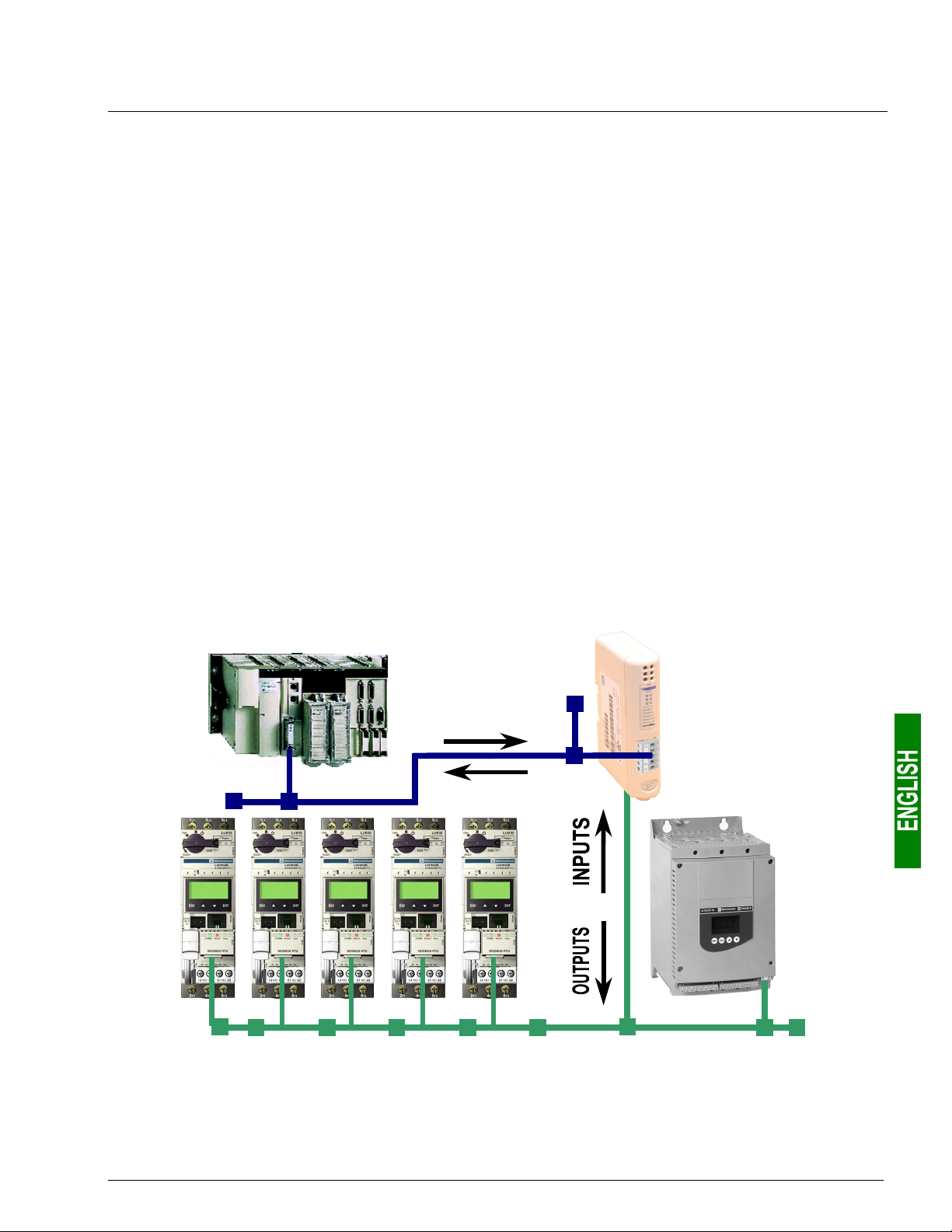
As is still the case with all communication systems, the terms “input” and “output” are somewhat ambiguous. To
avoid any confusion, we use a single convention throughout this document. So the notions of “input” and “output”
are always as seen from the PLC, or the DeviceNet master / scanner.
Hence, an “output” is a command signal sent to a Modbus slave, whereas an “input” is a monitoring signal
generated by this same Modbus slave.
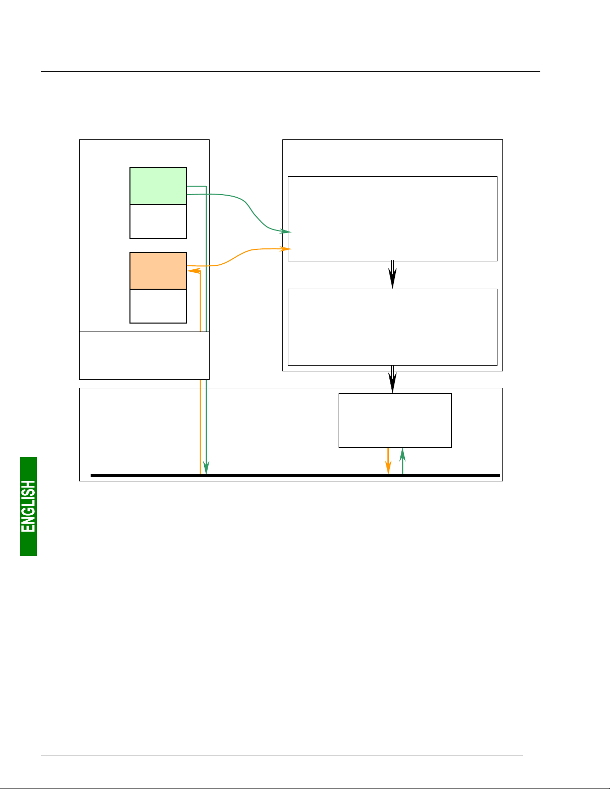
The diagram below shows the flows of “inputs” and “outputs” exchanged between a DeviceNet master and
Modbus RTU slaves via the LUFP9 gateway:
DeviceNet master
OUTPUTS
LUFP9
Gateway
INPUTS
Altistart 48
Modbus RTU Slaves
7

1. Introduction
1.4. Notational Conventions
16#•••• ..............Value expressed in hexadecimal, which is equivalent to the H••••, ••••h and 0x•••• notations,
sometimes used in other documents. N.B. The AbcConf software uses the 0x•••• notation.
E.g. 16#0100 = 0x0100 = 256.
02#•••• •••• ........Value expressed in binary. The number of ‘•’ digits depends on the size of the item of data
represented. Each nibble (group of 4 bits) is separated from the other nibbles by a space.
Examples: byte 2#0010 0111 = 39, word 2#0110 1001 1101 0001 = 16#69D1 = 27089.
AbcConf ...........Abbreviation that refers to the tool used to configure and implement the LUFP9 gateway: “ABC-
LUFP Configurator”.
ATS ..................Abbreviation of “Altistart” (soft start- soft stop unit).
ATV ..................Abbreviation of “Altivar” (drive).
CRC .................Cyclical Redundancy Check.
LED ..................Light-Emitting Diode.
EDS..................Electronic Data Sheet. Refers to the file format (“.eds” extension) which allow a tool used for
configuring and preparing DeviceNet masters to configure their exchanges using this same
protocol.
Fieldbus ...........A term referring to the upstream DeviceNet network in AbcConf.
Handshake.......An old term referring to the two registers used for initializing and carrying out diagnostics of the
LUFP9 gateway. This term has been replaced by the expression “Control/Status Byte”.
LRC..................Longitudinal Redundancy Check.
Node ................A term referring to the connection point of a Modbus slave under AbcConf.
ODVA...............Open DeviceNet Vendor Association, Inc.
LSB: .................Least significant byte in a 16-bit word.
MSB: ................Most significant byte in a 16-bit word.
Sub-Network ....A term referring to the downstream Modbus network under AbcConf.
XML..................EXtensive Markup Language. The language used by AbcConf to import/export the configuration
of a Modbus slave.
1.5. Additional Documentation
In the case of Modbus slaves, the features, services and adjustment of the Modbus communications are not
dealt with in this document.
8
1. Introduction
A
(
)
1.6. Introduction to the Communication “System” Architecture
DeviceNet
Master
Upstream network (DeviceNet)
Downstream
network no.1
(Modbus)
Total of 16
motor starters
(TeSys U model)
Downstream
network no.2
Modbus
ATS48
VW33-A48
VW3-G46301
Downstream network no.3 (Modbus)
TS46
9

1. Introduction
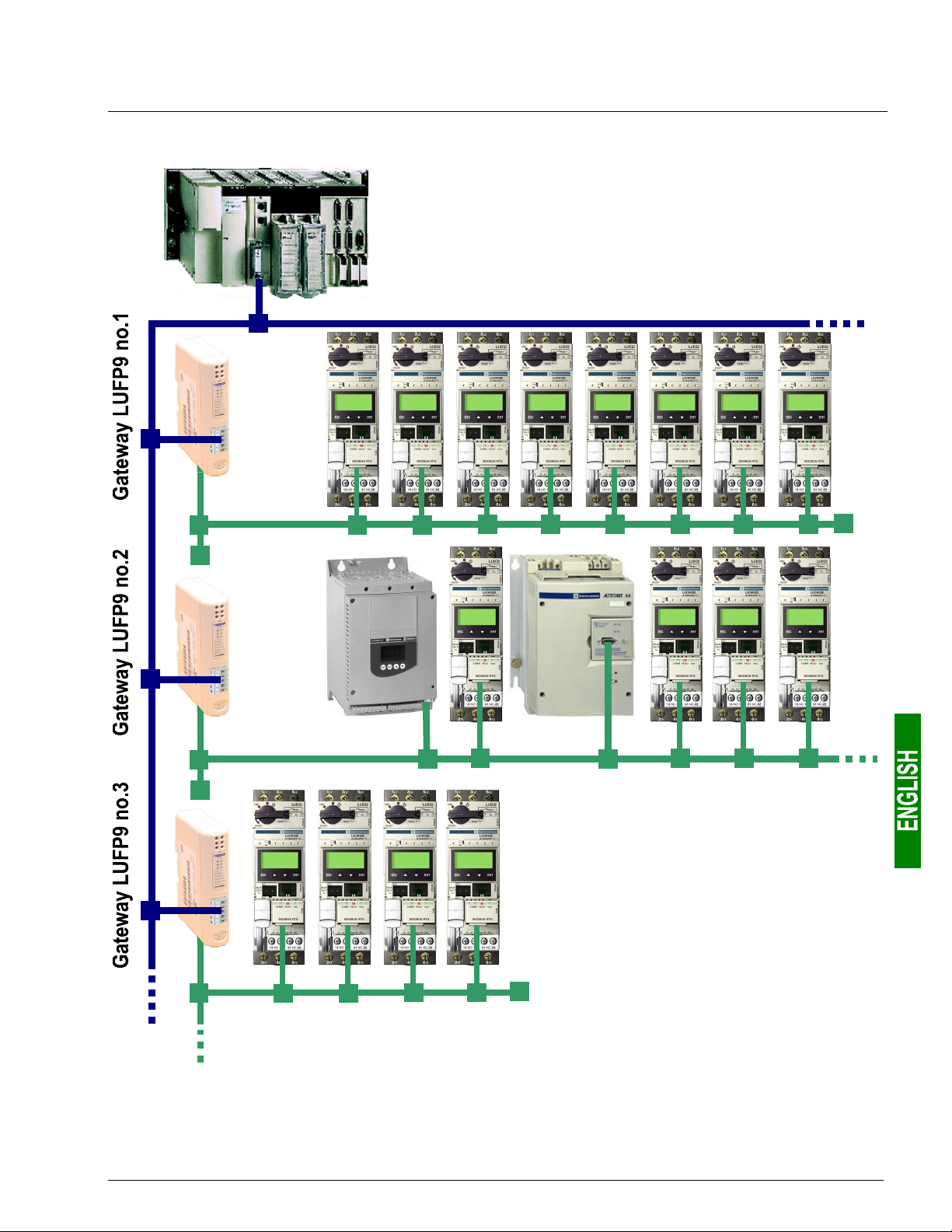
Each LUFP9 DeviceNet / Modbus RTU gateway allows a PLC on the DeviceNet network to command, control
and configure up to 8 Modbus slaves. If there are more than 8 Modbus slaves, you will need to use an
appropriate number of LUFP9 gateways. In the same way, if the exchanges with the Modbus slaves require
more than 25 Modbus commands (that is to say more than 50 queries and responses), you will have to distribute
the Modbus slaves over several gateways.
The LUFP9 gateway behaves both as a DeviceNet slave on the upstream network and as a Modbus RTU
master on the downstream network.
See chapter 7.2 Communication Characteristics, page 80, if you would like to read about the technical
communication characteristics of the LUFP9 gateway.
The gateway can carry out its data exchanges (inputs and outputs of all types) with the Modbus slaves cyclically,
aperiodically or in an event-driven way. All of these Modbus exchanges make up the gateway’s “Modbus
scanner” and we use the “ABC-LUFP Configurator” software application to configure this scanner’s exchanges.
Each item of data exchanged in this way is made available to the DeviceNet master, which can gain access to it
in a number of ways (cyclical, aperiodic or event-driven exchanges).
N.B. If, for example, a communication is periodic on the Modbus network, the corresponding data does not have
to be exchanged periodically on the DeviceNet network and vice versa.
The diagram on the page to the left illustrates the distribution of several slaves over three downstream Modbus RTU
networks, each of these networks being interfaced with the DeviceNet master PLC using an LUFP9 gateway.
1.7. Principle Used to Configure and Operate the LUFP9 Gateway
The gateway is part of a family of products (referred to as LUFPz) designed to meet generic needs for
connection between two networks using different communication protocols.
The software elements common to all these gateways (a configuration tool known as “ABC-LUFP Configurator”
and the on-board Modbus software) cohabit with the specific features of the network upstream of each of them
(DeviceNet in the case of the LUFP9 gateway) generically. This is one of the reasons why the interfacing between
the upstream network and the Modbus network is carried out entirely via the gateway’s physical memory.
Ö The exchanges between the gateway (which operates as a Modbus master) and the Modbus slaves are
wholly configured using the “ABC-LUFP Configurator”. This configuration tool goes into great detail (setting
timers for exchanges, communication modes, frame content, etc.), which makes it all the more delicate to
use. So a whole chapter in this guide (chapter 6 Configuring the Gateway, page 40) has been devoted to this
tool.
By configuring the queries and responses for Modbus commands via this tool the user can create links
between a part of the content of the corresponding Modbus frames and the content of the gateway’s physical
memory (input memory for the content of the Modbus responses and output memory for the content of the
queries).
Ö The exchanges between the DeviceNet master PLC and the LUFP9 gateway should be configured in such a
way that the DeviceNet master can read the input data and write the output data from the gateway, but only
the data used for the Modbus exchanges (see previous point).
10
1. Introduction
A
y
)
)
y
)
)
–––––––
–
Ö Each LUFP9 gateway is shipped pre-configured so as to make it easier to operate and the factory settings
can be used as a basis for a configuration which will best meet the user’s expectations. The typical
operations applicable to this default configuration are described in chapter 6 Configuring the Gateway,
page 40.
The DeviceNet network is totally separate from the Modbus network. The frames on a network are not directly
“translated” by the gateway to generate frames on the other network. Instead, the exchanges between the content
of the gateway’s memory and the Modbus slaves make up a system which is independent of the one which is
entrusted with managing the exchanges between this same memory and the DeviceNet master.
So the user must ensure that the size of the DeviceNet data corresponds to the size of the memory used for the
Modbus exchanges, because the gateway configures its DeviceNet exchanges on the basis of the memory used
by the Modbus frames.
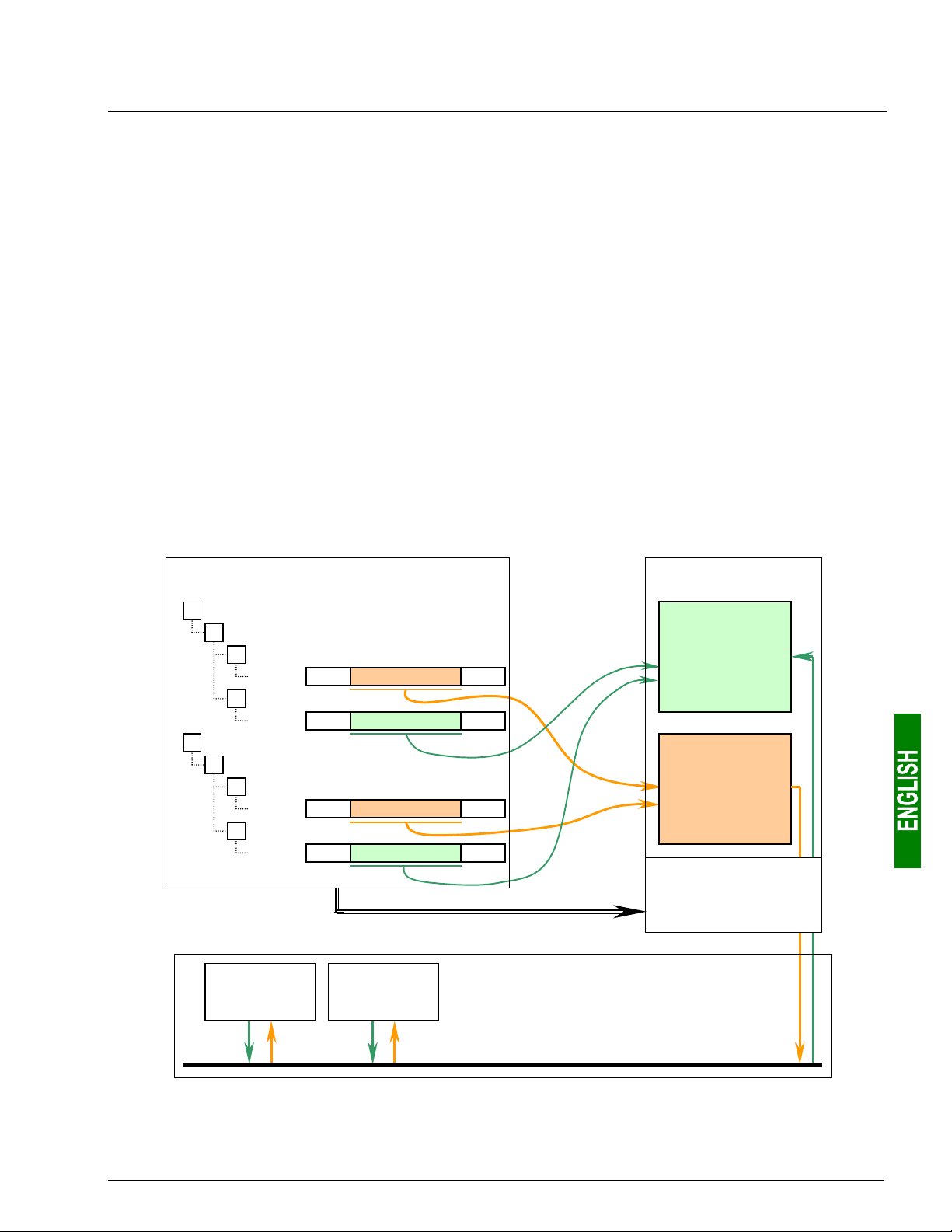
The two synopses which follow illustrate the independent management of each of the two networks:
— Managing Gateway ↔ Modbus slaves exchanges —
ABC Configurator
Slave
Command A1
A1RQ
Quer
Frame
→
• • • Data (Out
Response A1AQ
Frame
→
• • • Data (In
Slave B
Command B1
B1RQ
Quer
Frame →
Response B1AQ
Frame
Slave A Slave B
• • • Data (Out
→
• • • Data (In
Configuration of
Modbus exchanges
by the user
• • •
• • •
• • •
• • •
Transfer of the configuration
LUFP9 gateway
0x0000
:
Input
memory
:
0x01FF
:
0x0200
:
Output
memory
:
0x03FF
Managing
exchanges with the
Modbus slaves
Modbus network
11
1. Introduction
— Managing Gateway ↔ DeviceNet master exchanges —
LUFP9 gateway
0x0000
:
:
:
:
0x01FF
:
0x0200
:
:
:
:
0x03FF
Management of
exchanges with the
DeviceNet master
Input
Modbus
data
Free
memory
locations
:
Output
Modbus
Data
Free
memory
locations
DeviceNet
network
Configuration of the DeviceNet exchanges for the
master PLC by the user (excluding programming)
RSNetWorx
Configuration of DeviceNet exchanges :
♦ Type and address of the LUFP9 gateway
♦ Size of the input DeviceNet data
♦ Size of the output DeviceNet data
Export of the configuration
RSLogix 500
Direct transposition of the content of the gateway’s
memory into programming objects:
• Input Modbus data → I:x.y Objects
• Output Modbus data → O:x.y Objects
Transfer of the configuration
DeviceNet
master PLC
12
2. Hardware Implementation of the LUFP9 Gateway
2.1. On Receipt
After opening the packaging, check that the following element is there:
• One LUFP9 DeviceNet / Modbus RTU gateway.
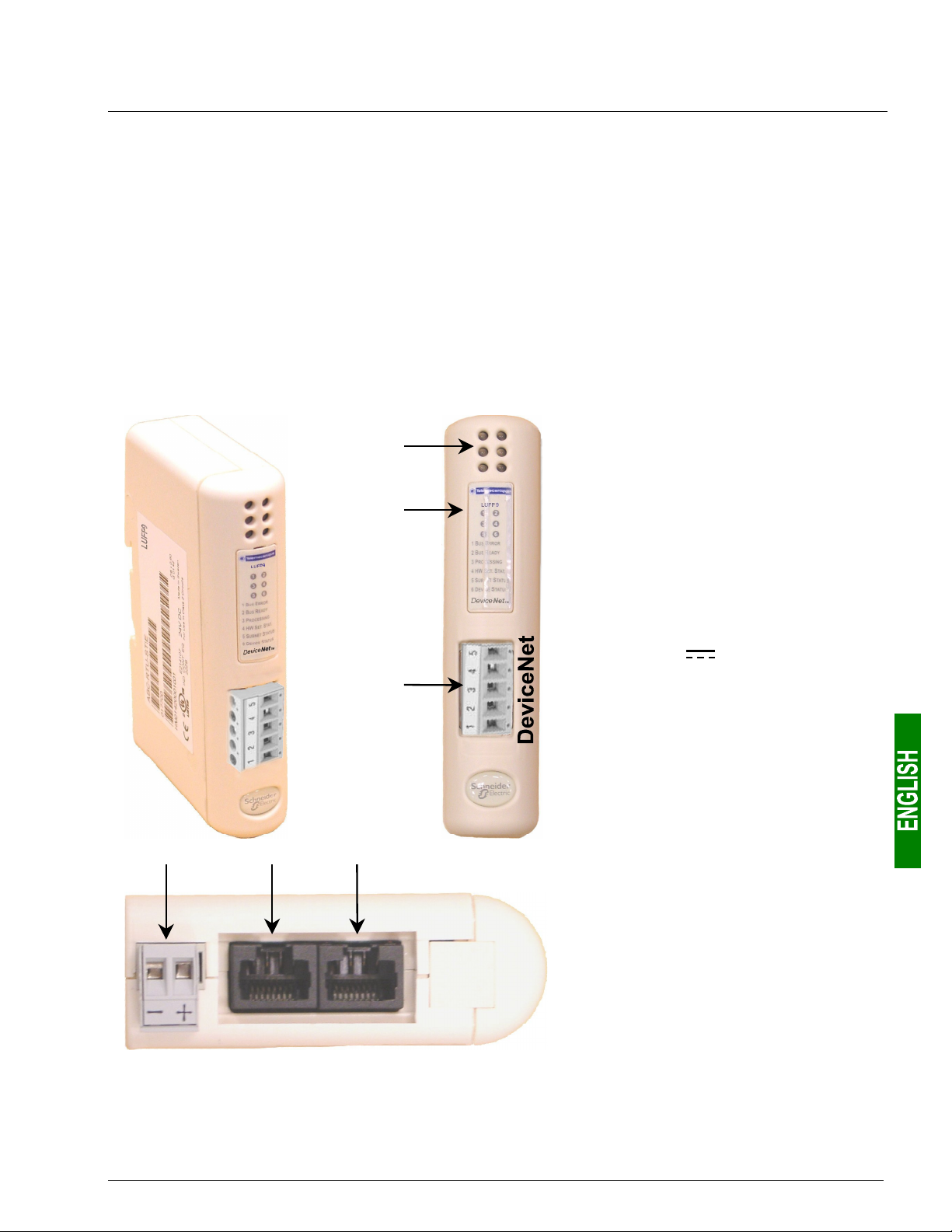
2.2. Introduction to the LUFP9 Gateway
The cables and other accessories for connecting to DeviceNet and Modbus networks need to be ordered
separately.
f
g
h
cde
Modbus RTUConfiguration
Legend:
c Detachable power connector for the
gateway (
24V ±10%).
d Female RJ45 connector to a PC
running AbcConf configuration
software.
e Female RJ45 connector for the
downstream Modbus RTU network.
f Six diagnostic LEDs.
g Removable cover for the selector
switches used to configure the
gateway, shown and described in
chapter 2.7 Configuring DeviceNet
Communication Features, page 20.
The label describing the LEDs is stuck
onto this cover.
h Detachable female DeviceNet
connector.
13
2. Hardware Implementation of the LUFP9 Gateway
2.3. Mounting the Gateway on a DIN Rail
Mounting the gateway
1
2
Start by fitting the rear base of the gateway to the
upper part of the rail, pushing downwards (1) to
compress the gateway’s spring. Then push the
gateway against the DIN rail (2) until the base of the
gateway box fits onto the rail.
Dismounting the gateway
1
2
Start by pushing the gateway downwards (1) to
compress the gateway’s spring. Then pull the
bottom of the gateway box forwards (2) until the box
comes away from the rail.
N.B. The spring is also used to earth the gateway (Protective Earth).
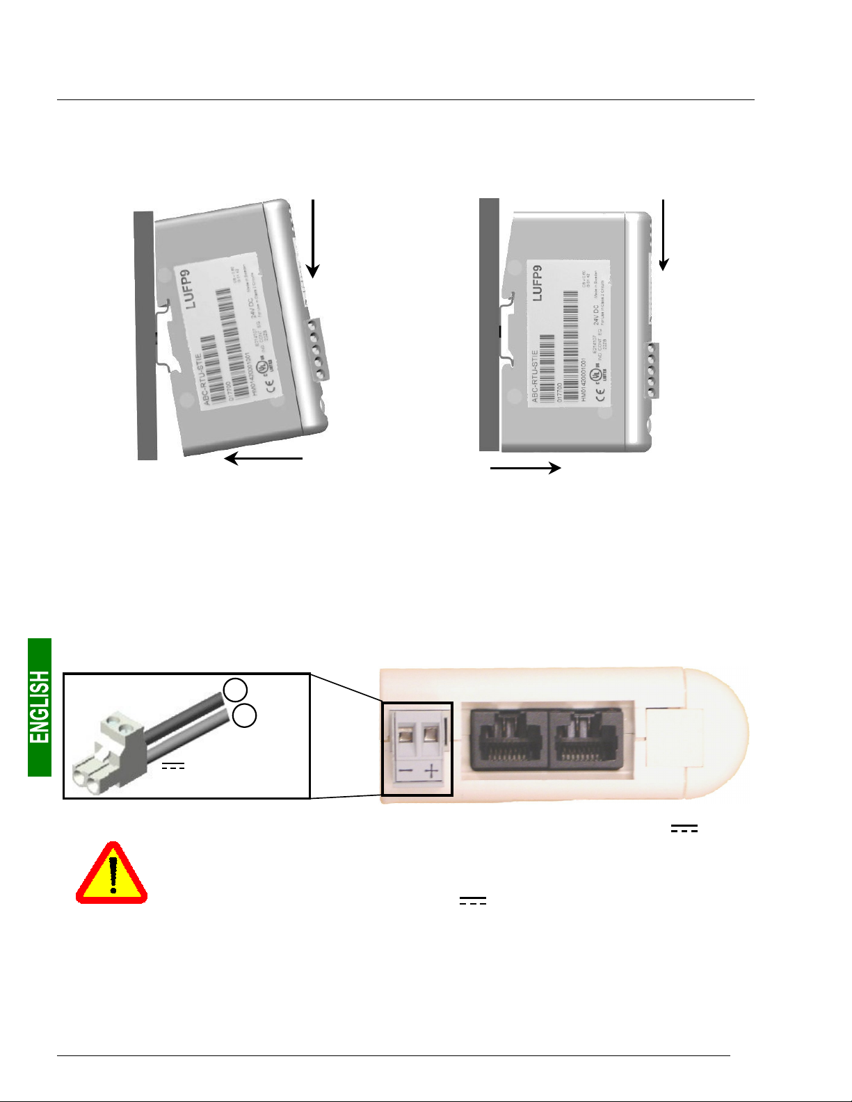
2.4. Powering the gateway
DeviceNet / Modbus RTU gateway – View from underneath
–
+
Power supply
24V isolated (±10%)
95 mA max.
We do not recommend powering the gateway using the 24V power voltage on the
DeviceNet network. It is better to use a separate power supply, because the gateway needs to
be powered using a stabilised voltage, which is not necessarily the case with the power
voltage on the DeviceNet network.
N.B. The negative 24V power supply terminal
earth.
should be connected to the installation’s
14
2. Hardware Implementation of the LUFP9 Gateway
2.5. Connecting the Gateway to the Modbus Network
Three typical examples of Modbus connection for the gateway and its slaves are shown below. There are many
other possible Modbus connections, but they are not covered in this document.
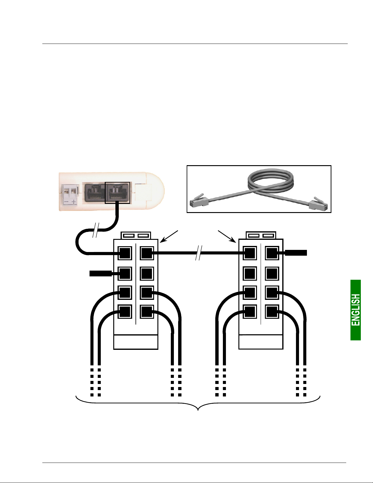
2.5.1. Examples of Modbus connection topologies
• “Star” topology: This topology uses LU9GC03 Modbus hubs, which have 8 female RJ45 connectors.
These hubs should be placed close to the Modbus slaves to which they are connected using
VW3 A8 306 R•• cables. On the other hand, the nature of the cable connecting the LUFP9 gateway to one
of these hubs will depend on the network architecture, so long as there is a male RJ45 connector at each
end. If necessary, one or two line terminations may be directly connected to the hubs.
The connections are shown below:
LUFP9 gateway
Modbus
Modbus
VW3 A8 306 R••
Line
termination
Modbus hubs
LU9GC03
Line
termination
Towards 8 Modbus slaves
15
2. Hardware Implementation of the LUFP9 Gateway
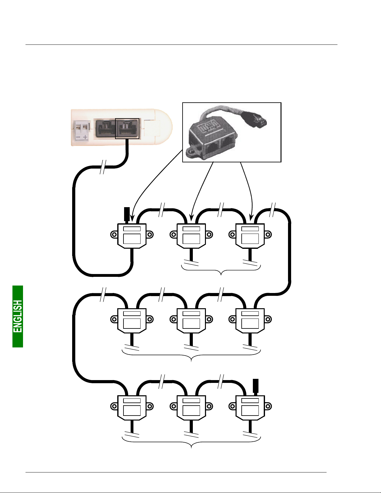
• “Bus” topology with VW3 A8 306 TF3 drop boxes: This topology uses VW3 A8 306 TF3 drop boxes to
connect each of the Modbus slaves to the main section of the Modbus network. Each box should be placed in
the immediate vicinity of the Modbus slave it is associated with. The cable for the main section of the Modbus
network must have male RJ45 connectors (like the VW3 A8 306 R•• cable used for the “star” topology). The
lead between the drop box and the slave or the Modbus gateway is an integral part of this box. The
connections are shown below:
LUFP9 gateway
Modbus
VW3 A8 306 TF3
Line
termination
Towards 2 Modbus slaves
Towards 3 Modbus slaves
Towards 3 Modbus slaves
Line
termination
16
2. Hardware Implementation of the LUFP9 Gateway
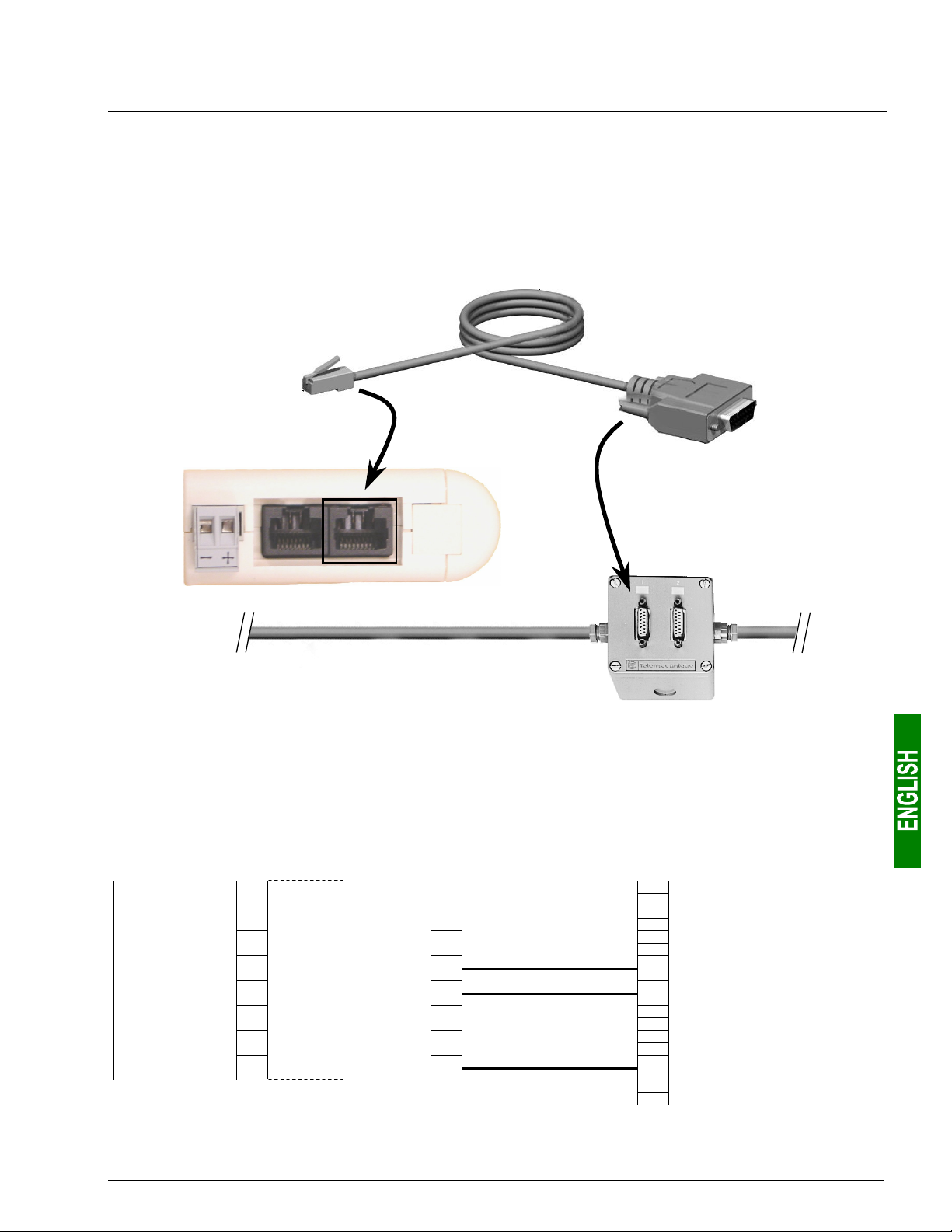
• “Bus” topology with tap boxes: This topology is similar to the previous one, except that it uses
TSXSCA62 subscriber connectors and/or TSXCA50 subscriber connectors. We recommend using a
VW3 A68 306 connection cable and the TSXCSA•00 Modbus cables. Connect the RJ45 connector on the
VW3 A68 306 cable to the Modbus connector on the LUFP9 gateway.
The connections are shown below:
VW3 A68 306
Modbus
TSXSCA62
LUFP9 gateway
TSXCSA•00
2.5.2. Pin outs
In addition to the pin out for the connector on the gateway, the one on the VW3 A68 306 cable is also shown
below, as it is the only Modbus cable which does not exclusively use RJ45 connections.
— LUFP9 connector —
Female RJ45 Male RJ45 Male 15-point SUB-D
11
2
3
D(B) 4
D(A) 5
6
7
0 V 8
———— VW3 A68 306 cable for TSXSCA62 box ————
2
3
D(B) 4 14 D(B)
D(A) 5 7 D(A)
6
7
0 V 8 15 0V
17
2. Hardware Implementation of the LUFP9 Gateway
r
r
2.5.3. Wiring recommendations for the Modbus network
• Use a shielded cable with 2 pairs of twisted conductors,
• connect the reference potentials to one another,
• maximum length of line: 1,000 metres
• maximum length of drop line / tap-off: 20 metres
• do not connect more than 9 stations to a bus (slaves and one LUFP9 gateway),
• cable routing: keep the bus away from power cables (at least 30 cm), make crossings at right angles if
necessary, and connect the cable shielding to the earth on each unit,
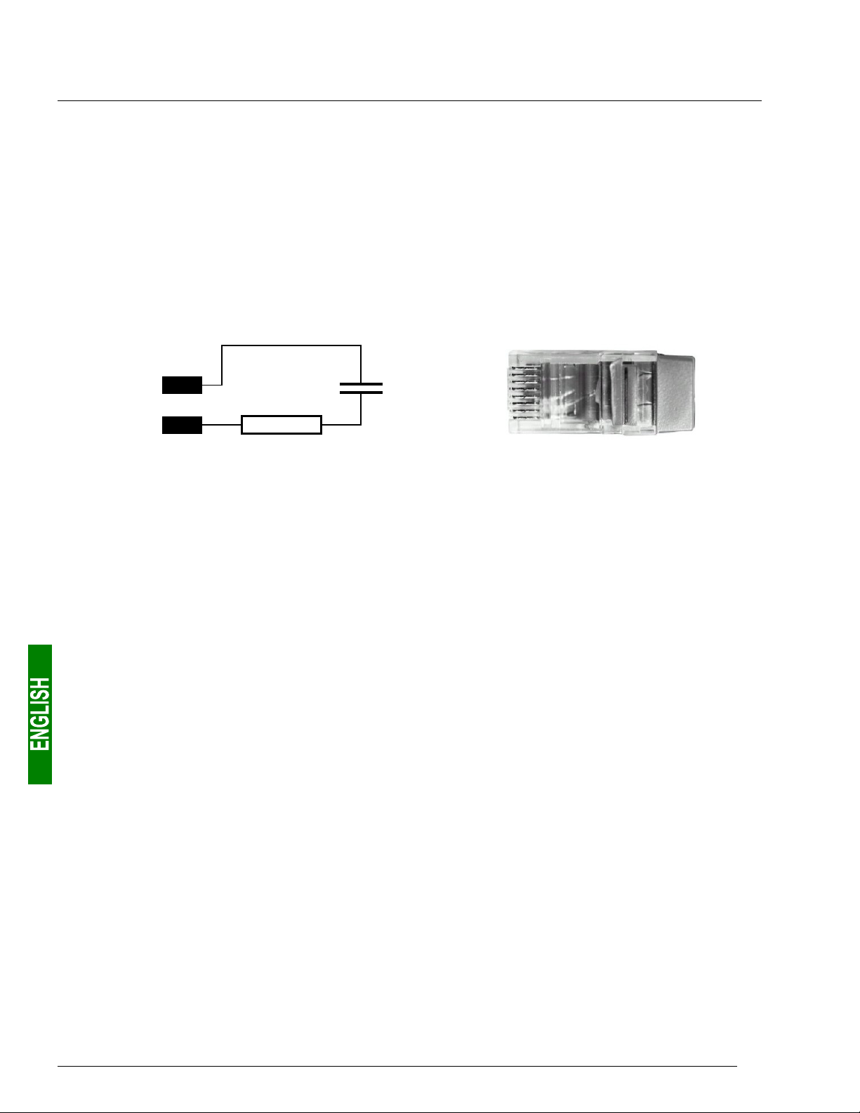
• adapt the line at both ends using a line terminator (see diagram and VW3 A8 306 RC termination below).
D(B)
D(A)
— Line termination recommended at both ends of the line — — VW3 A8 306 RC line termination —
To make it easier to connect the units using the topologies described in chapter 2.5.1 Examples of Modbus
connection topologies, page 15, various accessories are available in the Schneider Electric catalogue:
1) Hubs, drops, taps, and line terminations:
LU9GC03 hub.....................
(“star” topology)
VW3 A8 306 TF3 drop box......................
(“bus” topology with VW3 A8 306 TF3
drop boxes)
2-way TSXSCA62 subscriber connector .
(“bus” topology with branch boxes)
4
120 Ω
1 nF
5
This passive box has 8 female RJ45 connectors. Each of these connectors can
be connected to a Modbus slave, to a Modbus master, to another Modbus hub,
or to a line termination.
This passive box includes a short lead with a male RJ45 connecto
allowing it to be connected directly to a Modbus slave, without
having to use a different cable. It is fitted with 2 female RJ45
connectors for the connection of two Modbus cables of the
VW3 A8 306 R•• type.
This passive box has a printed circuit fitted with screw terminals
and allows the connection of 2 subscribers to the bus (2 female
15 point SUB-D connectors). It includes the line termination when
the connector is located at the end. It is fitted with 2 screw terminals
for the connection of two double twisted pair Modbus cables.
TSXCA50 tap box....................................
(“bus” topology with tap boxes)
VW3 A8 306 RC double termination .......
(all topologies)
18
This passive box allows a Modbus unit to be connected to a screw
terminal. It includes the line termination when the connector is
located at the end. It is fitted with 2 screw terminals for the
connection of two double twisted pair Modbus cables.
Each of these two red passive boxes is a male RJ45 connecto
3 cm long containing an RC line termination (see diagram and
illustration above). Only the abbreviation “RC” is shown on these
boxes.
2. Hardware Implementation of the LUFP9 Gateway
2) Cables:
VW3 A8 306 R•• Modbus cable ...................................
(“star” topology / “bus” topology with tap boxes)
VW3 A68 306 Modbus cable........................................
(“bus” topology with tap boxes)
Shielded double twisted pair Modbus cable.................
(“bus” topology with branch boxes)
Shielded cable with a male RJ45 connector at each
end.
Shielded cable with a male RJ45 connector and a
male 15-point SUB-D connector. It is used to connect
a Modbus subscriber (slave or master) to a
TSXSCA62 or TSXCA50 box.
Bare cable (without connectors) used to make up the
main section of the Modbus network. There are three
items available: TSXCSA100 (100 m), TSXCSA200
(200 m), and TSXCSA500 (500 m).
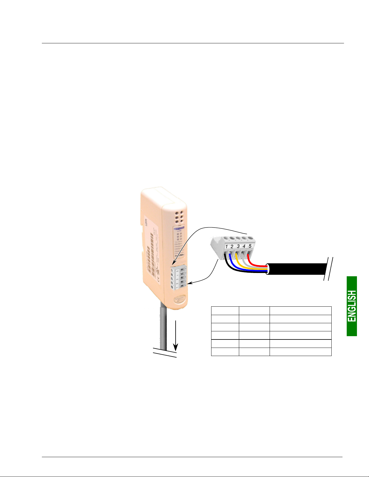
2.6. Connecting the LUFP9 gateway to the DeviceNet network
If the LUFP9 gateway is
physically located either end of
the DeviceNet network, you will
need to connect a line
termination to the terminals on
its DeviceNet connector.
The resistance of this line
termination should be equal to
121 Ω and it should be
connected between pins 2 and 4
on the gateway connector, that
is to say between the CAN_L
and CAN_H signals.
LUFP9
Gateway
Detachable female
connector
DeviceNet cable
Modbus
Pinouts
Pin Name Wire colour
1GNDBlack
2 CAN_L Blue
3 SHIELD None (bare wire)
4CAN_HWhite
5V+Red
19
2. Hardware Implementation of the LUFP9 Gateway
A
)
A
)
2.7. Configuring DeviceNet Communication Features
This configuration should be carried out when the gateway is powered off.
The block of selector switches allowing you to configure the DeviceNet communication functions is hidden
behind the gateway cover
remove this cover, all you have to do is slide the end of a small screwdriver between the top of the cover and the
gateway box, then carefully remove it.
The power supply of the gateway must be turned off before opening the cover.
Once the cover has been removed, make sure that you touch neither the electrical circuits nor
the electronic components.
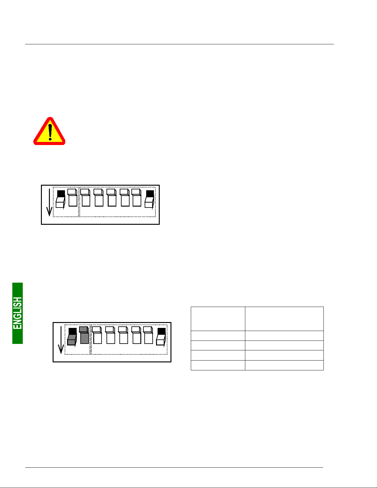
The block of selector switches is shown in the diagram below, each switch being shown in its factory set
position:
(see illustration in chapter 2.2 Introduction to the LUFP9 Gateway, page 13). To
g
Speed
2 3 4 5 6 8
1 7
ON
2.7.1. Encoding DeviceNet Speed
The gateway’s communication speed on the DeviceNet network must be identical to that of the DeviceNet
master.
The factory setting is 500 kbits/s.
This speed value depends on the position of selector switches 1 and 2.
Speed
1 7
ON
ddress (Mac ID
ddress (Mac ID
2 3 4 5 6 8
A selector switch is in the 0 state when it is in the OFF
position and in the 1 state when it is in the ON position.
Any change to the gateway’s communication
functions will not be effective until the next time
that the gateway is powered on.
Selector
switches
1 2 3 4 5 6 7 8
0 0 x x x x x x 125 kbits/s
0 1 x x x x x x 250 kbits/s
1 0 x x x x x x 500 kbits/s
1 1 x x x x x x Invalid configuration
DeviceNet speed
20
2. Hardware Implementation of the LUFP9 Gateway
(
)
A
)
A
)
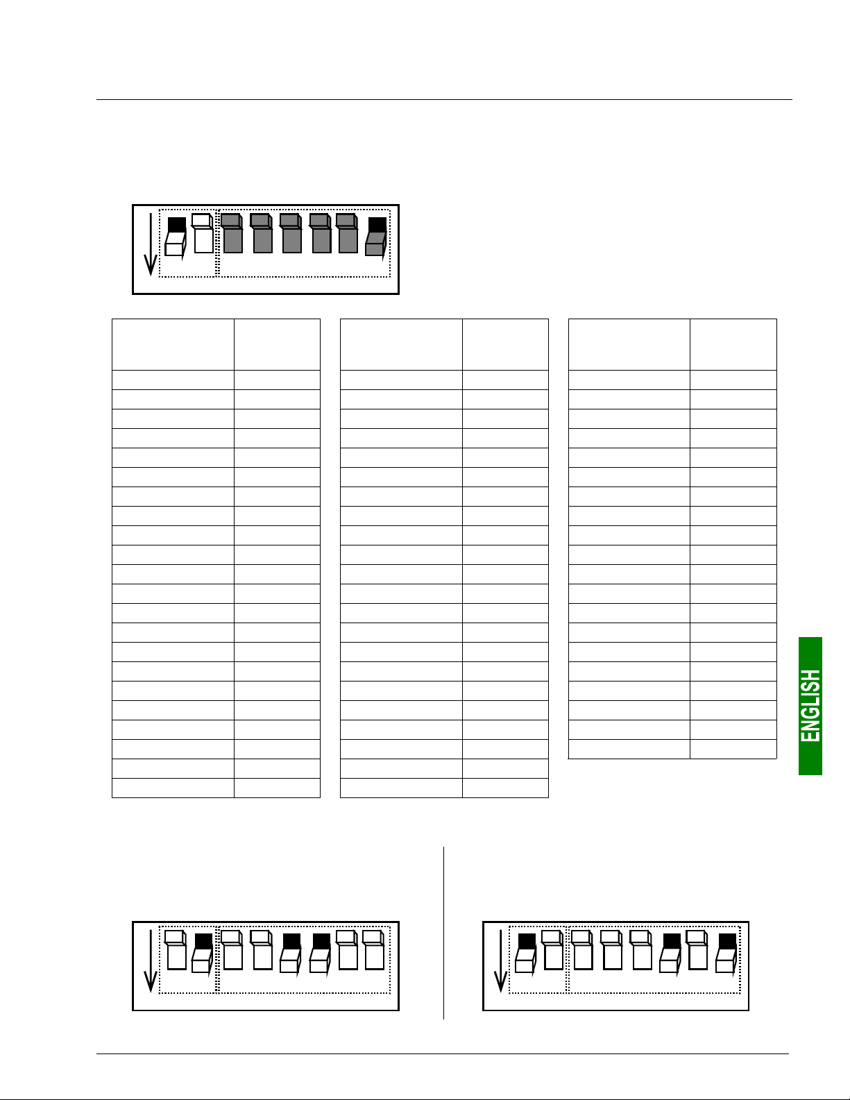
2.7.2. Encoding the Gateway Address
The LUFP9 gateway is identified on the DeviceNet bus by its address (or “Mac ID”), which is between 0 and 63.
Speed
1 7
Address
2 3 4 5 6 8
Mac ID
The gateway’s DeviceNet address depends on the
position of selector switches 3 to 8. It corresponds to
the binary number given by the ON (1) or OFF (0)
position of these 6 selector switches.
ON
Selector
switches
1 2 3 4 5 6 7 8
x x 0 0 0 0 0 0 0 x x 0 1 0 1 1 0 22 x x 1 0 1 1 0 0 44
x x 0 0 0 0 0 1 1 x x 0 1 0 1 1 1 23 x x 1 0 1 1 0 1 45
x x 0 0 0 0 1 0 2 x x 0 1 1 0 0 0 24 x x 1 0 1 1 1 0 46
x x 0 0 0 0 1 1 3 x x 0 1 1 0 0 1 25 x x 1 0 1 1 1 1 47
x x 0 0 0 1 0 0 4 x x 0 1 1 0 1 0 26 x x 1 1 0 0 0 0 48
x x 0 0 0 1 0 1 5 x x 0 1 1 0 1 1 27 x x 1 1 0 0 0 1 49
x x 0 0 0 1 1 0 6 x x 0 1 1 1 0 0 28 x x 1 1 0 0 1 0 50
x x 0 0 0 1 1 1 7 x x 0 1 1 1 0 1 29 x x 1 1 0 0 1 1 51
x x 0 0 1 0 0 0 8 x x 0 1 1 1 1 0 30 x x 1 1 0 1 0 0 52
x x 0 0 1 0 0 1 9 x x 0 1 1 1 1 1 31 x x 1 1 0 1 0 1 53
x x 0 0 1 0 1 0 10 x x 1 0 0 0 0 0 32 x x 1 1 0 1 1 0 54
x x 0 0 1 0 1 1 11 x x 1 0 0 0 0 1 33 x x 1 1 0 1 1 1 55
x x 0 0 1 1 0 0 12 x x 1 0 0 0 1 0 34 x x 1 1 1 0 0 0 56
x x 0 0 1 1 0 1 13 x x 1 0 0 0 1 1 35 x x 1 1 1 0 0 1 57
x x 0 0 1 1 1 0 14 x x 1 0 0 1 0 0 36 x x 1 1 1 0 1 0 58
x x 0 0 1 1 1 1 15 x x 1 0 0 1 0 1 37 x x 1 1 1 0 1 1 59
x x 0 1 0 0 0 0 16 x x 1 0 0 1 1 0 38 x x 1 1 1 1 0 0 60
x x 0 1 0 0 0 1 17 x x 1 0 0 1 1 1 39 x x 1 1 1 1 0 1 61
x x 0 1 0 0 1 0 18 x x 1 0 1 0 0 0 40 x x 1 1 1 1 1 0 62
x x 0 1 0 0 1 1 19 x x 1 0 1 0 0 1 41 x x 1 1 1 1 1 1 63
x x 0 1 0 1 0 0 20 x x 1 0 1 0 1 0 42
x x 0 1 0 1 0 1 21 x x 1 0 1 0 1 1 43
DeviceNet
address
Selector
switches
1 2 3 4 5 6 7 8
DeviceNet
address
Selector
switches
1 2 3 4 5 6 7 8
DeviceNet
address
2.7.3. Sample Gateway Configurations
Speed = 250 kbits/s
Address = 12
Speed
1 3 4 6
2 7 85
ddress (Mac ID
ON
Speed = 500 kbits/s
Address = 5
Speed
2 3 4 5 8
1 7
ddress (Mac ID
ON
6
21
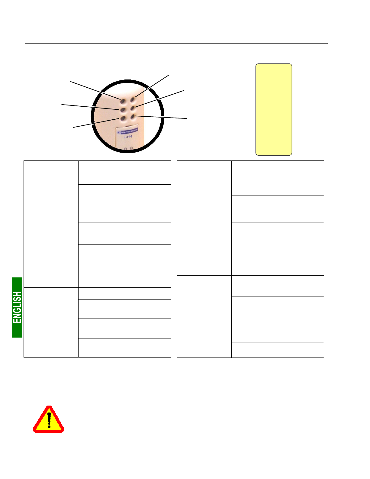
3. Signalling
The gateway’s 6 LEDs and the descriptive label on the removable cover which hides its block of selector
switches allow you to diagnose the status of the gateway:
d
c
f
e
h
g
telm
LUFP9
n
o
p
q
r
s
ETWORK STATUS
1 N
ODULE STATUS
2 M
OT USED
3 N
OT USED
4 N
ODBUS
5 M
TEWAY
6 GA
Net
Device
™
LED LED Æ Gateway state
Off: Gateway not connected to
the DeviceNet bus
Green: Gateway connected to
the DeviceNet bus:
Connection established
Red: Fatal error on connection
n
p
r
NETWORK
STATUS
NOT USED
MODBUS
to the DeviceNet bus
Flashing (green): Gateway
connected to the DeviceNet bus:
Connection not established
Flashing (red):Timeout in
connection to the DeviceNet bus
The length of this timeout is
defined by the DeviceNet master
Off: —
Off: No power
Flashing (green): No Modbus
communications
Green: Modbus
communications OK
Red: Loss of communication with
at least one Modbus slave (1)
LED LED Æ Gateway state
Off: No power
Red: Unrecoverable failure
MODULE
o
STATUS
Green: Gateway is operational
Flashing (red): Minor fault
q
s
NOT USED
GATEWAY
Off: —
Off: No power
Flashing (red/green):
Configuration absent / not valid
Use AbcConf to load a valid
configuration
Green: Gateway currently being
initialized and configured
Flashing (green): Gateway is in
running order: Configuration OK
(1) The LED r MODBUS becomes red whenever you use incorrect values in the outputs corresponding to the queries
of the two aperiodic services designed to read/write the value of any parameter of a Modbus slave (see chapter 4.2.8
Description of Services Assigned to Gateway Inputs/Outputs, page 31). This LED will only revert to its former
green state if you reuse these very same services, but with correct values. More generally, this LED becomes red,
then reverts to a green state, on loss and recovery of the communications with any Modbus slave.
N.B. If the DEVICE STATUS LED s is flashing following a sequence beginning with one or
more red flashes, we advise that you note down the order of this sequence and give this
information to the Schneider Electric support service.
In some cases, all you need to do is power the gateway off then back on again to solve the problem.
22
4. Software Implementation of the Gateway
y
4.1. Introduction
This chapter gives an introduction to a quick implementation of the LUFP9 gateway, using its default
configuration. All LUFP9 gateways ship pre-configured.
This pre-configuration means that the user does not have to configure the LUFP9 gateway using AbcConf. This
configuration is described in order to allow the gateway to be used with a configuration tool for DeviceNet master
PLCs. As an example this implementation will use RsNetWorx, the PLC configuration tool marketed by Allen
Bradley (e.g. SLC500).
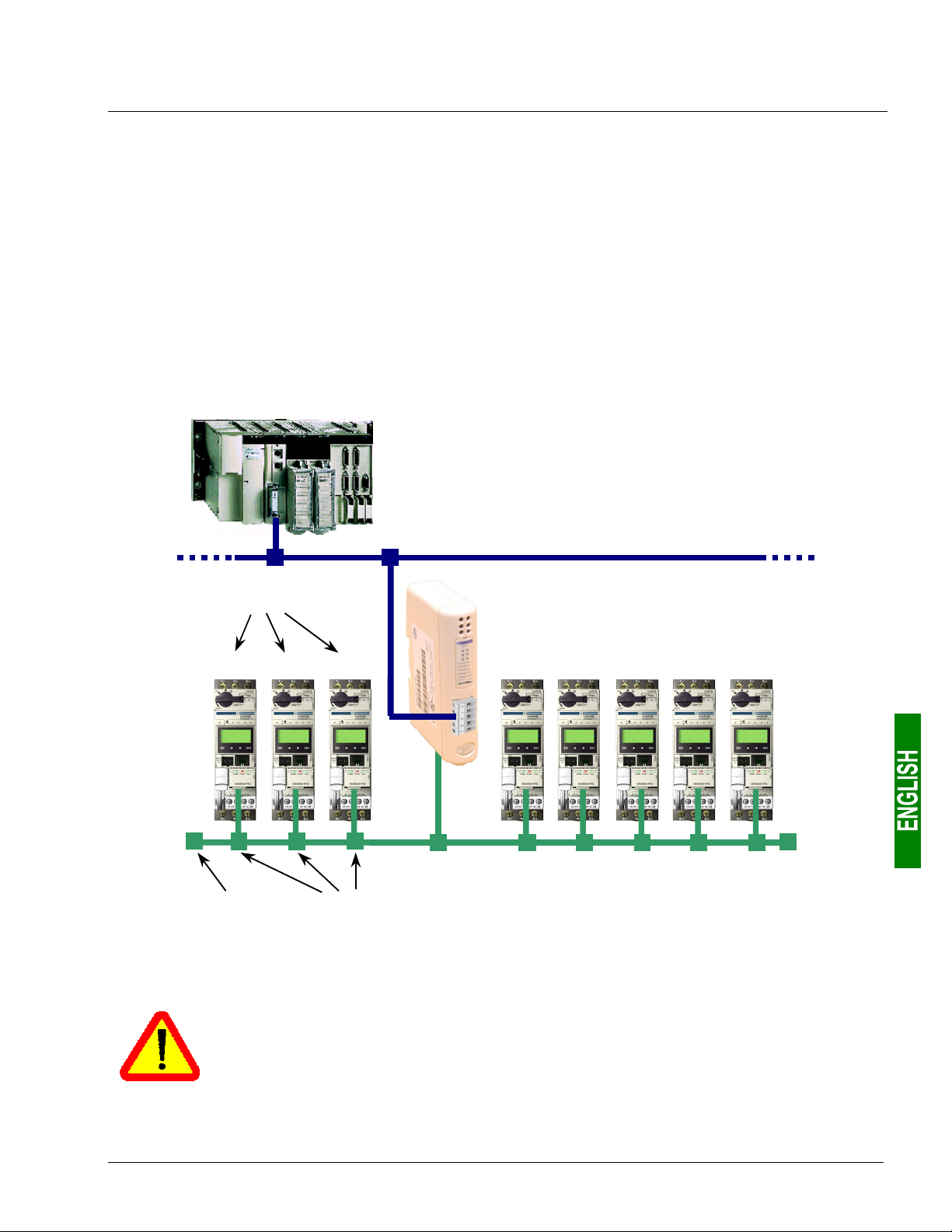
4.1.1. System Architecture
The default configuration for an LUFP9 gateway allows it to control, monitor and configure 8 TeSys U motor
starters:
DeviceNet
master PLC
(SLC500)
DeviceNet (upstream network)
Modbus
addresses
LUFP9
Gatewa
Total of 8
motor starters
(TeSys U model)
cde fghij
Modbus (downstream network)
Line
termination
Please see chapter 2 Hardware Implementation of the LUFP9 Gateway, page 13, for the hardware
implementation of the default configuration.
If you are using fewer than 8 TeSys U motor starters, you will need to adapt the gateway
configuration using the “ABC-LUFP Configurator” software (see chapter 6 Configuring the
Gateway, page 40, and chapter 6.6 Deleting a Modbus Slave, page 45).
Connection
boxes
23
4. Software Implementation of the Gateway
4.1.2. Configuring the Motor Starters
Each motor starter should be configured as follows:
Protocol: Modbus RTU slave Start bits 1
Modbus address 1 to 8 Parity None
Bitrate 19,200 bits/s Parity bit 0
Data bits 8 Stop bits 1
When using a TeSys U motor starter with a Modbus communication module (LULC031 module), the
configuration parameters for the RS485 connection are automatically detected, only the Modbus address needs
to be configured.
4.1.3. Modbus cycle time
The LUFP9 gateway’s default configuration sets a cycle time of 300 ms on Modbus commands for each of the
8 TeSys U motor starters.
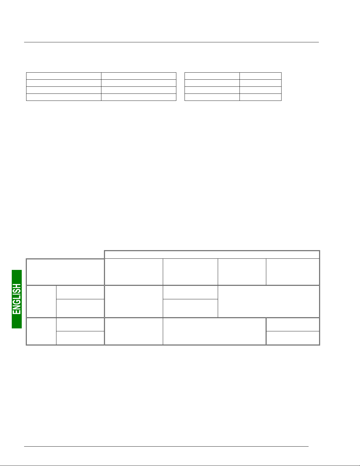
4.1.4. Managing degraded modes
The default management for degraded modes is described below, but it takes no account of the PLC used or of
the DeviceNet scanner. Please see chapter 6.11.2.1 Managing Degraded Modes, page 65, if you would like to
change the way that degraded modes for one or more Modbus commands are managed.
Event
Desired behaviour
Reset
Outputs
Hold
Reset
Inputs
Hold
(1) The desired behaviour with regard to the outputs should be directly configured on each of the TeSys U motor starters.
DeviceNet PLC:
CPU stop or failure
Depending on the
configuration
of the DeviceNet
master
——
Disconnection of
the upstream
DeviceNet network
Yes
——
Depending on the configuration
of the DeviceNet master
LUFP9 gateway
Depending on the configuration of the
Failure of the
TeSys U motor starters (1)
Disconnection
of the downstream
Modbus RTU
network
Yes
——
You can also read the user manuals for your master and your DeviceNet scanner to obtain further details about
how to process degraded modes.
24
4. Software Implementation of the Gateway
4.2. Configuring the Gateway in RsNetWorx
The DeviceNet master PLC must be configured so that it has access to all of the data described in
chapters 8.2.1 Input Data Memory Area, page 84 et 8.2.2 Output Data Memory Area, page 85.
The following chapters describe the steps in RsNetWorx which you will need to go through so that the gateway is
correctly recognised by the DeviceNet master PLC.
The DeviceNet network which is described in the following chapters only includes one master
and one slave (LUFP9 gateway). So you will need to adapt the addressing of the inputs and
outputs shown below (%IW and %QW) according to any other slaves on the DeviceNet
network which you need to configure.
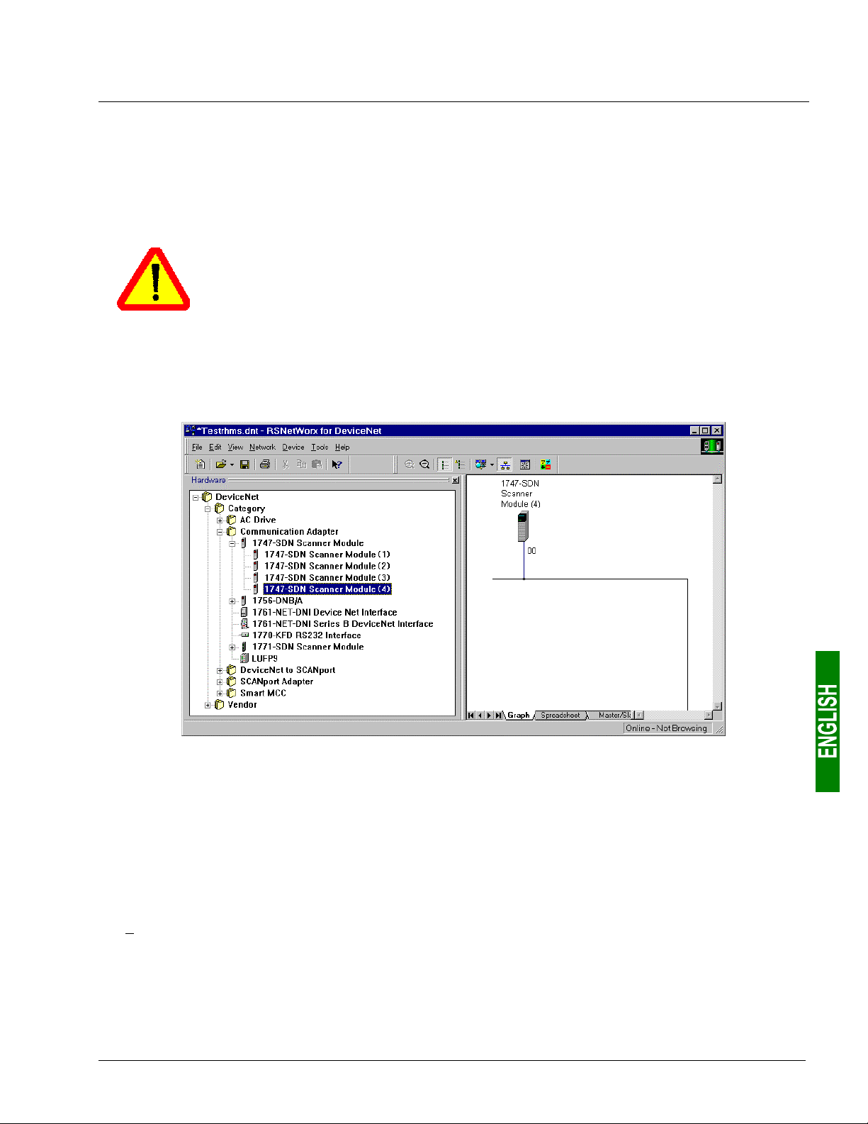
4.2.1. Selecting and adding the master PLC’s DeviceNet scanner
In RsNetWorx, select the type of scanner you have and add it to the DeviceNet network topology.
In our example, this scanner is a “1747-SDN Scanner Module (4)” and its Mac ID address is set to 00.
4.2.2. Installing the Gateway Description File
The EDS file describing the gateway must be placed on the PC’s hard disk so that RsNetWorx has access to it
at all times. The best thing is to place this file in the directory which holds all of the EDS files used by
RsNetWorx.
This file can be found on the CD LUF9CD1 : “LUFP9_100.eds”.
Î Once you are inside RsNetWorx, see the documentation to read how to import an EDS file. This procedure
should then be applied to the file “LUFP9_100.eds”. It uses the “EDS wizard”, which is accessible from the
“Tools” menu.
The following two entries are then added to the tree structure for recognised DeviceNet products:
• DeviceNet / Category / Communication Adapter / LUFP9
• DeviceNet / Vendor / Schneider Automation / LUFP9
25
4. Software Implementation of the Gateway
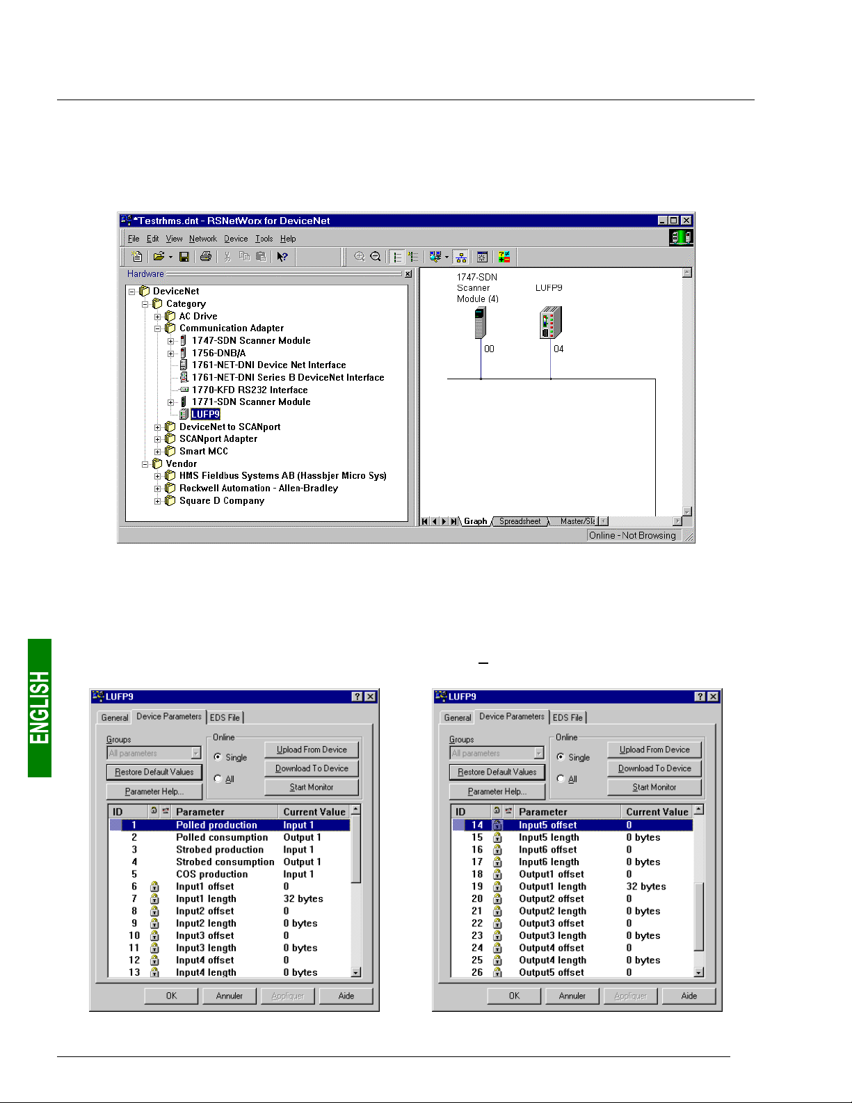
4.2.3. Selecting and Adding the Gateway to the DeviceNet Network
Select “LUFP9” from the list on the left, then add it to the DeviceNet network topology.
In our example, we have assigned the Mac ID address 04 to the gateway (the configuration of the address for a
gateway is described in chapter 2.7.2 Encoding the Gateway Address, page 21).
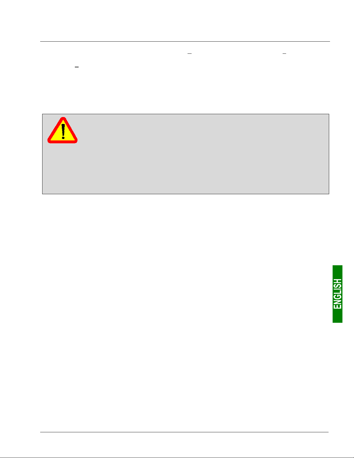
4.2.4. Editing gateway parameters
Double-click on the icon which corresponds to the gateway, in the frame on the right.
In the window which then appears, select the “Device Parameters” tab and check that the values for the
parameters correspond to those for the parameters shown below. If necessary, change them (only parameters 1
to 5 are accessible to the user in write mode), then click on the “Download To Device” button to send these
changes to the gateway.
26
4. Software Implementation of the Gateway
If you are in any doubt over what is displayed, click on the “Upload From Device” button, then on “Start Monitor”. The
RsNetWorx application then starts to read from the gateway the values of the parameters currently displayed.
Click on the “Stop Monitor” button to stop this reading process.
The most important parameters, in the case of the default gateway configuration, are parameters 1 and 2
(periodic transfers between the PLC and the gateway via a periodic connection known as “polled”), 6 and 7
(offset and size of the input data area in the gateway’s input memory), and 18 and 19 (offset and size of the
output data area in the gateway‘s output memory).
If you create or change a configuration using AbcConf (see chapter 6 Configuring the
Gateway, page 40), you should be aware that the values of these parameters should
correspond to the configuration of the data in the gateway’s memory, as defined in AbcConf.
This data corresponds to all of the bytes exchanged with the Modbus slaves via the “Data” or
“Preset Data” fields in the Modbus frames.
You should only check the parameters related to “Input1” and “Output1” areas. The other
parameters, related to “Input2” to “Input6” or to “Output2” to “Output6” areas, are intended for
an advanced use of the gateway, and Schneider Electric refuses to accept responsability for
their use. The operations needed to set the values of these parameters will not be described in
the current guide.
N.B. If a connection is not used, the corresponding EDS parameters are not used by the gateway. This is the
case with “Strobed” and “COS” connections (and EDS parameters nos. 3 to 5) when the default gateway
configuration is used. You can then retain the initial assignment of parameters nos. 1 to 5 to the two default input
and output areas (areas no. 1), because only the “Polled” connection (parameters nos. 1 and 2) will be activated
by the DeviceNet master.
N.B. The value of each “offset” type parameter refers to an offset from the start of the gateway’s input data
memory area or from the start of its output data memory area and not from the start of its physical memory.
27
4. Software Implementation of the Gateway
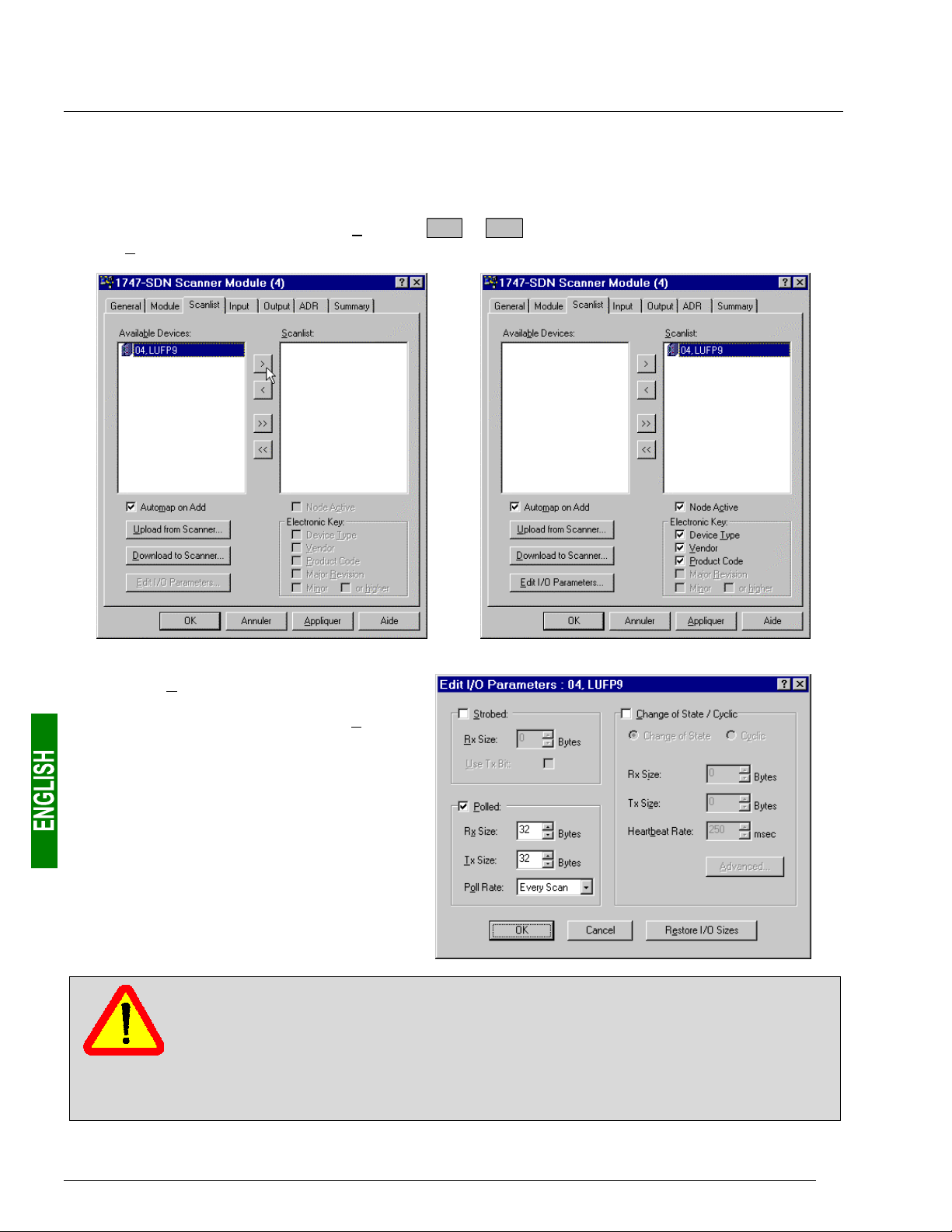
4.2.5. Configuring the DeviceNet Scanner
Double-click on the icon which corresponds to the DeviceNet scanner.
A window then appears allowing you to configure the exchanges carried out by the scanner. Select the “Scanlist”
tab and add the “LUFP9” gateway to the “Scanlist” (
list, the “Edit I/O Parameters…” button becomes accessible.
> or >> buttons). After selecting the gateway from this
Click on the “Edit I/O Parameters…” button.
In the window that appears, check the “Polled:”
box, then configure the size of the data
received (Rx = 32 bytes) and the size of the
data transmitted (Tx = 32 bytes) by the
scanner.
With the LUFP9 gateway’s default
configuration, these values allow you to
exchange all of the data shown in
chapters 8.2.1 Input Data Memory Area,
page 84, et 8.2.2 Output Data Memory Area,
page 85.
If you create or change a configuration using AbcConf (see chapter 6 Configuring the
Gateway, page 40), the sizes of the data exchanged via one of these connections must
correspond to the sizes of the “Input1” and “Output1” areas which have been assigned to it
using EDS parameters nos. 1 to 5 (see previous chapter).
Please see chapter 10.8 Connection Object (Class 16#05), page 99 for further information
about DeviceNet connections for the LUFP9 gateway. Please also see the documentation that
came with your DeviceNet master PLC.
28
4. Software Implementation of the Gateway
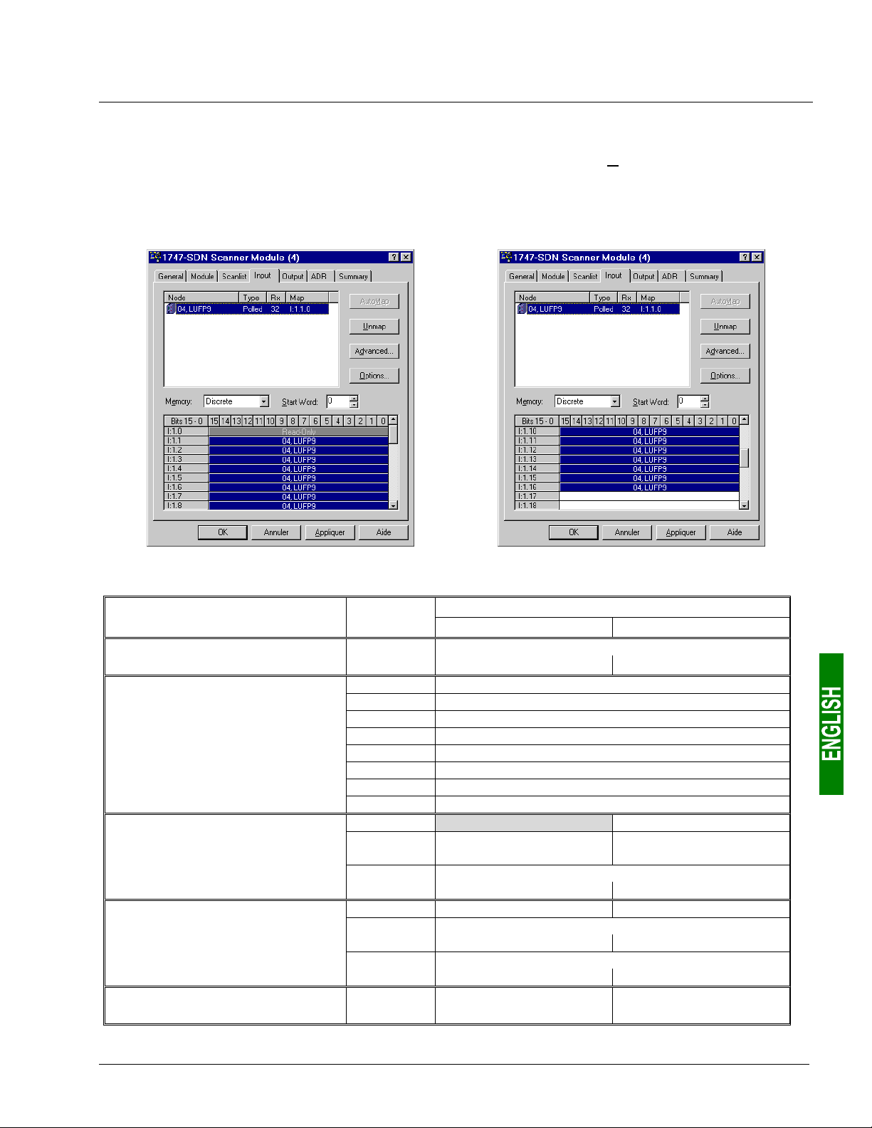
4.2.6. Configuring Inputs from the Gateway
On the “Input” tab, select the “LUFP9” gateway, then click on the “AutoMap” button. RsNetWorx then
automatically establishes the correspondence between the 32 data bytes (8-bit format) from the gateway and the
corresponding 16 PLC inputs “I:1.1” to “I:1.16” (16-bit format).
Please check that a correspondence between all of the data from the gateway and the PLC inputs “I:1.1” to
“I:1.16” has been established.
The correspondence between the contents of the gateway’s input memory (see chapter 8.2.1 Input Data Memory
Area, page 84) and PLC inputs “I:1.1” to “I:1.16” is given in the following table:
Service PLC input
Managing the downstream
Modbus network
Periodic communications
—
Monitoring of
TeSys U motor starters
Aperiodic communications
—
Reading the value of a
motor starter parameter (
Aperiodic communications
—
Writing the value of a
motor starter parameter (
Aperiodic communications
(“Trigger bytes” for the responses)
RESPONSE)
RESPONSE)
I:1.1
I:1.2
I:1.3
I:1.4
I:1.5
I:1.6
I:1.7
I:1.8
I:1.9
I:1.10
I:1.11
I:1.12
I:1.13
I:1.14
I:1.15
I:1.16
Bit 0......................Bit 7 Bit 8 ...................Bit 15
LUFP9 gateway status word
(MSB Æ 16#xx••) (LSB Æ 16#••xx)
Value of the motor starter c status register
Value of the motor starter d status register
Value of the motor starter e status register
Value of the motor starter f status register
Value of the motor starter g status register
Value of the motor starter h status register
Value of the motor starter i status register
Value of the motor starter j status register
Memory location free Slave no. (16#01-16#08)
Function number (16#03)
Value of the parameter read
(MSB Æ 16#xx••) (LSB Æ 16#••xx)
Slave no. (16#01-16#08) Function no. (16#06)
Address of the parameter written
(MSB Æ 16#xx••) (LSB Æ 16#••xx)
Value of the parameter written
(MSB Æ 16#xx••) (LSB Æ 16#••xx)
Read parameter
response counter
Description
Number of bytes
read (16#02)
Write parameter
response counter
29
4. Software Implementation of the Gateway
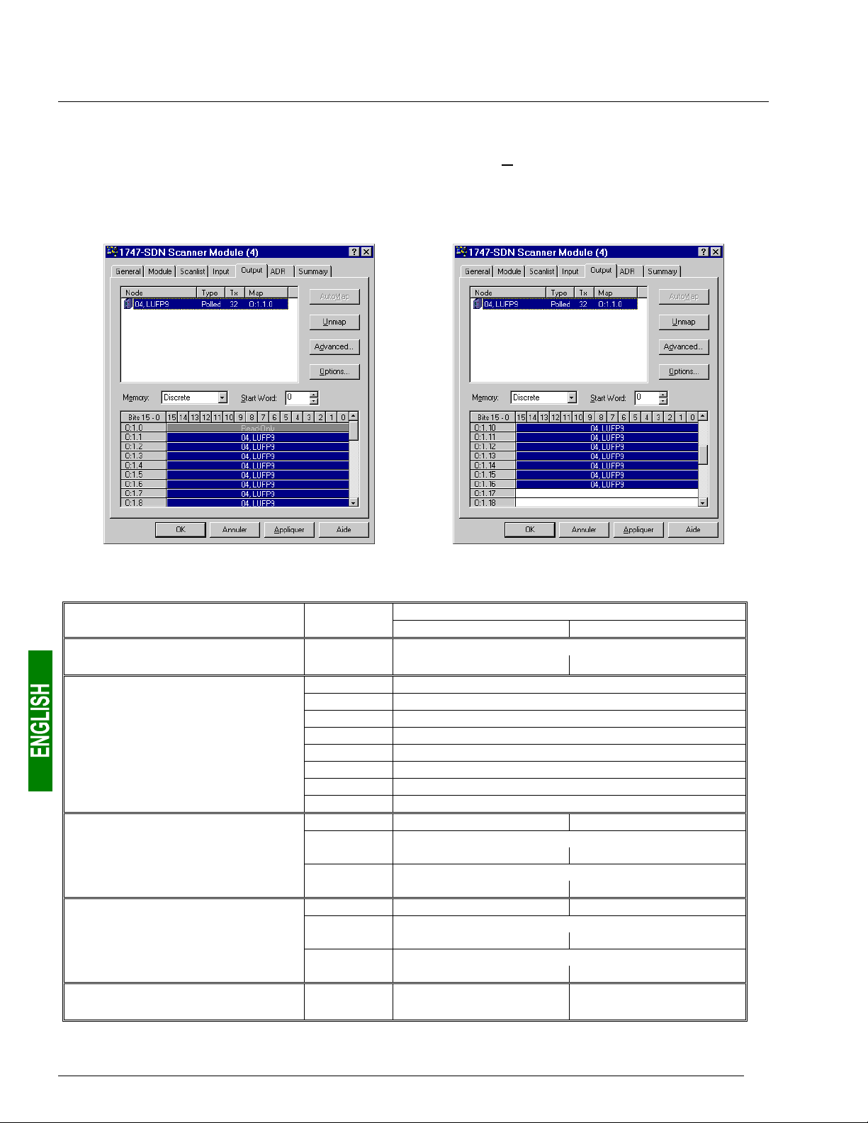
4.2.7. Configuring Outputs Intended for the Gateway
On the “Output” tab, select the “LUFP9” gateway, then click on the “AutoMap” button. RsNetWorx then automatically
establishes the correspondence between the 32 data bytes (8-bit format) to be sent to the gateway and the
corresponding 16 PLC outputs “O:1.1” to “O:1.16” (16-bit format).
Please check that a correspondence between all of the data sent to the gateway and the PLC outputs “O:1.1” to
“O:1.16” has been established.
The correspondence between the contents of the gateway’s output memory (see chapter 8.2.2 Output Data
Memory Area, page 85) and PLC outputs “O:1.1” to “O:1.16” is given in the following table:
Service PLC output
Managing the downstream
Modbus network
Periodic communications
—
Controlling
TeSys U motor starters
Aperiodic communications
—
Reading the value of a
motor starter parameter (Q
Aperiodic communications
—
Writing the value of a
motor starter parameter (Q
Aperiodic communications
(“Trigger bytes” for the queries)
UERY)
UERY)
O:1.1
O:1.2
O:1.3
O:1.4
O:1.5
O:1.6
O:1.7
O:1.8
O:1.9
O:1.10
O:1.11
O:1.12
O:1.13
O:1.14
O:1.15
O:1.16
Bit 0 ..................... Bit 7 Bit 8....................Bit 15
DeviceNet master command word
(MSB Æ 16#xx••) (LSB Æ 16#••xx)
Value of the motor starter c command register
Value of the motor starter d command register
Value of the motor starter e command register
Value of the motor starter f command register
Value of the motor starter g command register
Value of the motor starter h command register
Value of the motor starter i command register
Value of the motor starter j command register
Slave no. (16#01-16#08) Function no. (16#03)
Address of the parameter to be read
(MSB Æ 16#xx••) (LSB Æ 16#••xx)
Number of parameters to be read
(MSB Æ 16#00••) (LSB Æ 16#••01)
Slave no. (16#01-16#08) Function no. (16#06)
Address of the parameter to be written
(MSB Æ 16#xx••) (LSB Æ 16#••xx)
Value of the parameter to be written
(MSB Æ 16#xx••) (LSB Æ 16#••xx)
Read parameter
query counter
Description
Write parameter
query counter
30

4. Software Implementation of the Gateway
4.2.8. Description of Services Assigned to Gateway Inputs/Outputs
Managing the downstream Modbus network: Please see chapter 5.2 Diagnostic only, page 37, for a detailed
description of this service. The example described in chapter 9.1 Main Program: “LAD 2 - MAIN_LUFP9”,
page 86, only automatically acknowledges gateway diagnostics, that is to say it does not exploit the data from
these diagnostics. In the case of the gateway’s default configuration, under AbcConf, the “Control/Status Byte”
field of the “ABC” element is equal to “Enabled but no startup lock.”
Periodic communications (inputs): The value of each of the 8 words for this service corresponds to the value
of the status register of a TeSys U motor starter (register located at address 455).
Periodic communications (outputs): The value of each of the 8 words for this service corresponds to the value
to be sent to the command register for a TeSys U motor starter (register located at address 704).
Please see chapter 9.2 Controlling/Monitoring Sub-Program for a TeSys U Motor Starter: “LAD 3 - CMD_MON”,
page 87, for an example of the simplified use of these “periodic communications” services.
Aperiodic communications: Please see chapter 9.3 Sub-Program for Reading a Parameter in all TeSys U
Motor Starters: “LAD 4 - RD_PAR”, page 89, and chapter 9.4 Sub-Program for Writing a Parameter on a Single
TeSys U Motor Starter: “LAD 5 - WR_PAR”, page 91, for an example of how to use the “aperiodic
communications” services.
These aperiodic communications services offer functions similar to those of “parameter area PKW”, which can
be found on certain Schneider Electric products, such as some ATV drives.
The 16-bit inputs and outputs for which the MSB and LSB order is specified must be
used by the DeviceNet master inverting the LSB / MSB order so as to restore the value
of the corresponding item of Modbus data.
• Sample reading of a motor starter parameter:
Reading of the 1st fault register (address = 452 = 16#01C4) on “TeSys U n°5” motor starter. The initial
values of O:1.16 and I:1.16 are equal to 16#1306. The result of the reading is 16#0002 (magnetic fault).
Output Value Meaning (MSB + LSB) Input Value Meaning (MSB + LSB)
O:1.10
O:1.11
O:1.12
O:1.16
16#0305
16#C401
16#0100
16#1307
Function no. + Slave no. I:1.10
Parameter address (MSB
Number of parameters (MSB
“Trigger byte” for the query (Pf) I:1.16
↔LSB
↔LSB
)
)
I:1.11
I:1.12
16#0500
16#0203
16#0200
16#1307
Slave no. + (not used)
Number of bytes + Function no.
Value read (MSB
“Trigger byte” for the response (Pf)
↔LSB
)
• Sample writing of a motor starter parameter:
Writing of the 2nd command register (address = 705 = 16#02C1) on “TeSys U n°7” motor starter at the value
16#0006 (clear statistics + reset thermal memory). The initial values of O:1.16 and I:1.16 are equal to
16#1307. The result of the writing is a command echo, that is to say that the values of the “address
parameter” and “value to be written” fields are identical in both the query and the response.
Output Value Meaning (MSB + LSB) Input Value Meaning (MSB + LSB)
O:1.13
O:1.14
O:1.15
O:1.16
16#0607
16#C102
16#0600
16#1407
Function no. + Slave no. I:1.13
Parameter address (MSB
Value to be written (MSB
“Trigger byte” for the query (PF) I:1.16
↔LSB
↔LSB
)
)
I:1.14
I:1.15
16#0607
16#C102
16#0600
16#1407
Function no. + Slave no.
Parameter address (MSB
Value to be written (MSB
“Trigger byte” for the response (PF)
↔LSB
↔LSB
Avoid writing incorrect values in outputs which correspond to the aperiodic communication
services described above, as they would lead to the transmission of an incoherent Modbus
frame. In fact there is no check on the data used by these services and so it is up to the
DeviceNet master PLC application to manage them.
)
)
In addition, do not ever use these services in “Broadcast” mode (Modbus address = 0).
31

4. Software Implementation of the Gateway
4.2.9. Transferring the DeviceNet Scanner Configuration
Once you have finished the operations described above, make sure that the changes made have been
transmitted to the DeviceNet scanner. To do this, click on the “Download to Scanner…” button on each of the
“Module” and “Scanlist” tabs in the DeviceNet scanner properties window.
If necessary, please see the RsNetWorx documentation for further details on this subject.
4.2.10. Developing a DeviceNet Application
The DeviceNet master PLC used as an example is a SLC500, marketed by Allen Bradley. An example of a PLC
application, developed in RSLogix 500, is shown in chapter 9 Appendix C: Practical Example (RSLogix 500),
page 86. This example uses the PLC, the gateway and the 8 TeSys U motor starters shown in the Software
Implementation of the Gateway.
32

5. Gateway Initialization and Diagnostics
Each of the three sub-chapters 5.1, 5.2 and 5.3 describes the principle used to initialize and carry out
diagnostics on the gateway using each of the three options offered by the gateway. These options can be
configured via AbcConf, by changing the assignment of the “Control/Status Byte” field for the “ABC” element
(see chapter 6.12.2 “ABC” Element, page 76). The links between these sub-chapters and these options are as
follows:
“Control/Status Byte” field .............................Sub-chapter ...................................Page
Enabled ..............................................................5.1 Full Management ........................ 33
Enabled but no startup lock
Disabled .............................................................5.3 Simplified Operation.................... 39
The option chosen in the default configuration is “Enabled but no startup lock.”
5.1. Full Management
Until it receives an order to start up the Modbus exchanges from the DeviceNet master, the
LUFP9 gateway does not transmit any queries on the Modbus network. The DeviceNet master
can then deactivate these exchanges by inverting this startup order. Subsequently these two
orders may be reiterated by the DeviceNet master.
..............................5.2 Diagnostic only............................ 37
The Modbus exchange startup order is located in a 16-bit register occupying the addresses 16#0200 and
16#0201 in the gateway’s memory (outputs). A second 16-bit register, located at the addresses 16#0000 and
16#0001 (inputs), allows the gateway to send diagnostics to the DeviceNet master.
So you must configure your DeviceNet master so that it has access to the first two bytes of the
gateway’s output data area, as well as to the first two bytes of the gateway’s input data area (see
chapter 4.2 Configuring the Gateway in RsNetWorx, page 25).
5.1.1. DeviceNet Master Command Word
The output word located at addresses 16#0200 (MSB) and 16#0201 (LSB) in the gateway’s output memory
constitutes the DeviceNet master command word. Its structure is described below:
Bits Description
15
FB_HS_CONFIRM: Acknowledgement bit of a gateway diagnostic
The DeviceNet master must compare the value of the FB_HS_CONFIRM bit to the value of the
ABC_HS_SEND bit (bit 15 in the gateway’s status word). If these two values are different, this means
that the gateway has transmitted a new diagnostic to the DeviceNet master.
To tell the gateway that it has read a diagnostic, the DeviceNet master must copy the value of the
ABC_HS_SEND bit to the FB_HS_CONFIRM bit. This allows the gateway to issue a new diagnostic.
Summary:
• If ( FB_HS_CONFIRM = ABC_HS_SEND ) Æ The gateway’s status word contains a diagnostic
which has already been acknowledged by the DeviceNet master. So the gateway is free to use
this status word to place another diagnostic there.
• Else Æ A new diagnostic is available in the gateway’s status word. The DeviceNet master can
read this diagnostic, but must also copy the value of ABC_HS_SEND to FB_HS_CONFIRM in
order to allow the gateway to generate new diagnostics.
33

5. Gateway Initialization and Diagnostics
Bits Description
14
FB_HS_SEND: New command from the DeviceNet master
Before changing the value of FB_DU, the DeviceNet master must compare the values of
FB_HS_SEND and ABC_HS_CONFIRM (bit 14 of the gateway’s status word). If these two values are
different, this means that the gateway has not yet acknowledged the previous DeviceNet master
command. Else, the DeviceNet master can issue a new command, updating the FB_DU bit according
to the nature of its command (shutdown or activation of Modbus exchanges), then toggling the value
of the FB_HS_SEND bit to inform the gateway that it has sent it a new command.
Summary:
• If ( FB_HS_SEND ≠ ABC_HS_CONFIRM ) Æ The DeviceNet master command word still
contains a command which has not yet been acknowledged by the gateway. So the DeviceNet
master cannot use this word to place a new command in it.
• Else Æ The previous command of the DeviceNet master has been acknowledged by the
gateway, which allows it to transmit a new command. In this case, it changes the value of the
FB_DU bit, then toggles the value of the FB_HS_SEND bit.
13
FB_DU: Modbus exchange startup
The setting of this bit to one by the DeviceNet master allows communications between the gateway
and the Modbus slaves. Resetting it to zero is used to inhibit them.
When the DeviceNet master sets this bit to one, it is preferable for all of the output data it has placed
in the gateway’s output memory to be up-to-date (“FB_DU” means “FieldBus – Data Updated”). If
they are not, this data will be transmitted to the Modbus slaves “as it”.
0-12 Reserved.
Due to the inversion of the LSB and the MSB for this register between the gateway and the DeviceNet master,
the structure of the corresponding output word (“O:1.1” in the case of the default configuration) is as follows:
Bits Description
8-15 Reserved.
7
FB_HS_CONFIRM: Acknowledgement bit of a gateway diagnostic
6
FB_HS_SEND: New DeviceNet master command word
5
FB_DU: Modbus exchange startup
0-4 Reserved.
e.g. If the O:1.1 output word is set to 16#00A0, the DeviceNet master command word will be set to 16#A000.
The correct use of this command word by the DeviceNet master, to transmit a new command to the gateway,
goes through the following steps:
• Checking of (FB_HS_SEND = ABC_HS_CONFIRM).
• The command, that is to say the value of the FB_DU bit, is updated.
• The value of the FB_HS_SEND bit is inverted.
N.B. It is possible to simplify this use as follows:
• The FB_DU and FB_HS_SEND bits are set to one to activate the Modbus communications.
• The FB_DU and FB_HS_SEND bits are reset to halt Modbus communications.
On the other hand, do not write directly in 16-bit format in the DeviceNet master command word, because this
would disrupt the operation of the transfer of the gateway diagnostics (undesired change to FB_HS_CONFIRM).
However, during some debug or test phase, you could, for instance, write 16#6000 in the DeviceNet master
command word (that is to say 16#0060 in the O:1.1 output word) in order to activate the Modbus
communications, and 16#0000 to stop them.
34

5. Gateway Initialization and Diagnostics
5.1.2. Gateway Status Word
The input word located at addresses 16#0000 (MSB) and 16#0001 (LSB) in the gateway’s input memory
constitutes the gateway’s status word. Its structure is described below:
Bits Description
15
ABC_HS_SEND: New gateway diagnostic
(See description of bit 15 of the DeviceNet master command word, FB_HS_CONFIRM.)
14
ABC_HS_CONFIRM: Acknowledgement bit of a DeviceNet master command
(See description of bit 14 of the DeviceNet master command word, FB_HS_SEND.)
13
ABC_DU: Modbus exchanges activated
The gateway activates this bit to tell the DeviceNet master that the Modbus data located in its input
memory area have all been updated at least once since the last activation of FB_DU (“ABC_DU”
means “ABC – Data Updated”). These Modbus input data include every data in responses from all
Modbus slaves, for both periodic commands and aperiodic commands.
This bit is deactivated by the gateway when the FB_DU bit is deactivated, that is to say when the
DeviceNet master demands a shutdown of Modbus exchanges.
N.B. Once it is active, this bit is not deactivated if there are any communication errors with the
Modbus slaves. To signal this type of error, the gateway uses bit 12 of its status word.
12
Periodicity of Modbus exchanges
The gateway activates this bit provided that it is periodically communicating with all of the Modbus
slaves. It deactivates it as soon as it loses communication with one of them.
The “Reconnect time (10ms)”, “Retries” and “Timeout time (10ms)” elements of each of the Modbus
queries (see chapter 6.11.2.2 Configuring the Query, page 66) are used to determine whether
communication is lost, then restored.
N.B. If a number of periodic exchanges are configured for the same Modbus slave, only one of them
needs to remain active for the periodic communications with this slave to be declared active.
8-11
0-07
EC: Error code associated with the Modbus network
Code for the error detected on the Modbus network by the gateway and transmitted to the DeviceNet
master.
ED: Error data item associated with the Modbus network
Data item associated with the EC error code.
Due to the inversion of the LSB and the MSB for this register between the gateway and the DeviceNet master,
the structure of the corresponding input word (“I:1.1” in the case of the default configuration) is as follows:
Bits Description
8-15
0-3
E.g. If the gateway’s status word is set to 16#F031, the input word I:1.1 will be set to 16#31F0.
ED: Error data item associated with the Modbus network
7
ABC_HS_SEND: New gateway diagnostic
6
ABC_HS_CONFIRM: Acknowledgement bit of a DeviceNet master command
5
ABC_DU: Modbus exchanges activated
4
Periodicity of Modbus exchanges
EC: Error code associated with the Modbus network
35

5. Gateway Initialization and Diagnostics
The correct use of this status word by the DeviceNet master, to read a diagnostic generated by the gateway,
goes through the following steps:
• Checking of (ABC_HS_SEND ≠ FB_HS_CONFIRM).
• Reading of the value of ABC_DU to determine whether all of the Modbus input data are up-to-date.
• Reading of the value of the “Periodicity of Modbus exchanges” bit to determine whether the periodicity of
the Modbus communications has been maintained.
• Reading of the values of EC and ED to check for any error detected by the gateway on the Modbus
network (see table below).
• Copying of the value of the ABC_HS_SEND bit to the FB_HS_CONFIRM bit.
This last step is essential because it allows the gateway to transmit a future diagnostic! Even if you do not wish
to read the content of the gateway’s status word, it is preferable to automate this step in your DeviceNet master
software.
The values of the EC and ED fields are described in the table below:
EC Description of the error ED Notes
2#0000 Re-transmissions on the
Modbus network
2#0001 A Modbus slave is missing Address of the missing
2#0010 Several Modbus slaves
are missing
2#0011 Excessive data in a
Modbus response
2#0100 Unknown Modbus error
Number of re-
transmissions (1)
Modbus slave
——
Address of the Modbus
slave involved
Address of the Modbus
slave involved
Total number of re-transmissions carried out
on the sub-network, for all slaves.
—
This error occurs when the gateway receives too
much data in the response sent by one of its
Modbus slaves.
—
(1) The re-transmission counter used to signal this error is not reset when the gateway generates this error
code. If there are recurrent communication problems on the Modbus network, the gateway will generate this
same diagnostic repeatedly, so as to tell the DeviceNet master the total number of re-transmissions carried
out as often as possible. This counter is reset when its value exceeds its maximum value (counter modulo
256: 16#FF Æ 16#00).
36

5. Gateway Initialization and Diagnostics
5.2. Diagnostic only
The gateway uses a 16-bit register, located at the addresses 16#0000 and 16#0001 in its memory (inputs), to
send diagnostics to the DeviceNet master. A second 16-bit register, located at the addresses 16#0200 and
16#0201 (outputs), allows the DeviceNet to acknowledge each of these diagnostics.
So you must configure your DeviceNet master so that it has access to the first two bytes of the
gateway’s output data area, as well as to the first two bytes of the gateway’s input data area (see
chapter 4.2 Configuring the Gateway in RsNetWorx, page 25).
5.2.1. Gateway Status Word
The input word located at addresses 16#0000 (MSB) and 16#0001 (LSB) in the gateway’s input memory
constitutes the gateway’s status word. Its structure is described below:
Bits Description
15
ABC_HS_SEND: New gateway diagnostic
(See description of bit 15 of the DeviceNet master command word, FB_HS_CONFIRM.)
14 Reserved.
13
ABC_DU: Modbus exchanges activated
The gateway activates this bit to tell the DeviceNet master that the Modbus data located in its input
memory area have all been updated at least once since the last activation of FB_DU (“ABC_DU”
means “ABC – Data Updated”). These Modbus input data include every data in responses from all
Modbus slaves, for both periodic commands and aperiodic commands.
This bit is deactivated by the gateway when the FB_DU bit is deactivated, that is to say when the
DeviceNet master demands a shutdown of Modbus exchanges.
N.B. Once it is active, this bit is not deactivated if there are any communication errors with the
Modbus slaves. To signal this type of error, the gateway uses bit 12 of its status word.
12
Periodicity of Modbus exchanges
The gateway activates this bit provided that it is periodically communicating with all of the Modbus
slaves. It deactivates it as soon as it loses communication with one of them.
The “Reconnect time (10ms)”, “Retries” and “Timeout time (10ms)” elements of each of the Modbus
queries (see chapter 6.11.2.2 Configuring the Query, page 66) are used to determine whether
communication is lost, then restored.
N.B. If a number of periodic exchanges are configured for the same Modbus slave, only one of them
needs to remain active for the periodic communications with this slave to be declared active.
8-11
0-07
EC: Error code associated with the Modbus network
Code of the error detected on the Modbus network by the gateway and transmitted to the DeviceNet
master.
ED: Error data item associated with the Modbus network
Data item associated with the EC error code.
37

5. Gateway Initialization and Diagnostics
Due to the inversion of the LSB and the MSB for this register between the gateway and the DeviceNet master,
the structure of the corresponding input word (“I:1.1” in the case of the default configuration) is as follows:
Bits Description
8-15
0-3
E.g. If the gateway’s status word is set to 16#B031, the input word I:1.1 will be set to 16#31B0.
The correct use of this status word by the DeviceNet master, to read a diagnostic generated by the gateway,
goes through the following steps:
• Checking of (ABC_HS_SEND ≠ FB_HS_CONFIRM).
• Reading of the value of ABC_DU to determine whether all of the Modbus inputdata are up-to-date.
• Reading of the value of the “Periodicity of Modbus exchanges” bit to determine whether the periodicity of
ED: Error data item associated with the Modbus network
7
ABC_HS_SEND: New gateway diagnostic
6 Reserved.
5
ABC_DU: Modbus exchanges activated
4
Periodicity of Modbus exchanges
EC: Error code associated with the Modbus network
the Modbus communications has been maintained.
• Reading of the values of EC and ED to check for any error detected by the gateway on the Modbus
network (see table on page 36).
• Copying of the value of the ABC_HS_SEND bit to the FB_HS_CONFIRM bit.
This last step is essential because it allows the gateway to transmit a future diagnostic! Even if you do not wish
to read the content of the gateway’s status word, it is preferable to automate this step in your DeviceNet master
software.
5.2.2. DeviceNet Master Command Word
The output word located at addresses 16#0200 (MSB) and 16#0201 (LSB) in the gateway’s output memory
constitutes the DeviceNet master command word. Its structure is described below:
Bits Description
15
FB_HS_CONFIRM: Acknowledgement bit of a gateway diagnostic
The DeviceNet master must compare the value of the FB_HS_CONFIRM bit to the value of the
ABC_HS_SEND bit (bit 15 in the gateway’s status word). If these two values are different, this means
that the gateway has transmitted a new diagnostic to the DeviceNet master.
To tell the gateway that it has read a diagnostic, the DeviceNet master must copy the value of the
ABC_HS_SEND bit to the FB_HS_CONFIRM bit. This allows the gateway to issue a new diagnostic.
Summary:
• If ( FB_HS_CONFIRM = ABC_HS_SEND ) Æ The gateway’s status word contains a diagnostic
which has already been acknowledged by the DeviceNet master. So the gateway is free to use
this status word to place another diagnostic there.
• Else Æ A new diagnostic is available in the gateway’s status word. The DeviceNet master can
read this diagnostic, but must also copy the value of ABC_HS_SEND to FB_HS_CONFIRM in
order to allow the gateway to generate new diagnostics.
0-14 Reserved.
38

5. Gateway Initialization and Diagnostics
Due to the inversion of the LSB and the MSB for this register between the gateway and the DeviceNet master,
the structure of the corresponding output word (“O:1.1” in the case of the default configuration) is as follows:
Bits Description
8-15 Reserved.
7
FB_HS_CONFIRM: Acknowledgement bit of a gateway diagnostic
0-6 Reserved.
E.g. If the O:1.1 output word is set to 16#0080, the DeviceNet master command word will be set to 16#8000.
5.3. Simplified Operation
The two 16-bit registers located at addresses 16#0000-16#0001 (inputs) and 16#0200-16#0201 (outputs) are no
longer used for “managing the downstream Modbus network”. These two registers are no longer reserved and
so these addresses can be used to exchange data with the Modbus slaves (“Data Location” attribute of “Data” or
“Preset Data” type frame fields).
The DeviceNet master’s command word and the gateway’s status word, which we will be talking about in the rest
of this document, do not exist anymore. So the two warnings on pages 51 and 55 should be ignored, and the
input and output ranges in the gateway’s memory therefore go respectively from 16#0002-16#01FF to 16#000016#01FF and from 16#0202-16#03FF to 16#0200-16#03FF.
If the gateway’s default configuration were to be configured in this way, it would clear DeviceNet scanner input
“I:1.1” and output “O:1.1”. These two words would then become “free memory locations”.
39

6. Configuring the Gateway
Each part of this chapter describes a separate step allowing the user to personalize the gateway configuration,
according to his own particular needs. Each part gives an introduction to a basic operation isolating it from the
rest of the configuration and describing the operations to be carried out using AbcConf (mainly) and RsNetWorx
(where necessary), and their implications for the gateway’s general behaviour.
In each case, the first two steps are required, as they allow you to establish the dialogue between the gateway
and the PC software allowing you to configure it, that is to say AbcConf.
We strongly recommend that you read chapter 4 Software Implementation of the Gateway, page 23, because all
of the operations carried out in AbcConf or RsNetWorx are based on the principle that we are using the default
configuration of the LUFP9 gateway.
6.1. Connecting the Gateway to the Configuration PC
This step is required when setting up the gateway configuration application, AbcConf.
Connecting the gateway to one of the serial (COM) ports on a PC requires a straight PowerSuite cable and a
RS232/RS485 converter. These two items are the same as those allowing dialogue with drives and soft startsoft stop units using the PowerSuite application and are both available from the catalogue (ref.: VW3 A8 106).
Ensure that you use the “POWERSUITE” cable and the “RS232 / RS485 PC” converter. An “ATV28 before 09 /
2001” cable and an “ATV 58” converter are also supplied with these items, but they should not be used with the
LUFP9 gateway.
LUFP9 gateway (Seen from underneath)
Configuration
RS485
RJ45
VW3 A8 106
RJ45
Straight POWERSUITE cable
PC
Male
SubD 9
RS232 / RS485
converter
RS232
(COM)
Female
SubD 9
Once the gateway has been connected to a PC with the PowerSuite cable and the RS232/RS485 converter, you
can change its configuration using “ABC-LUFP Configurator”, more generally referred to as “AbcConf”. This
configurator also allows you to carry out a few diagnostics on the gateway.
40

6. Configuring the Gateway
6.1.1. Pin Outs
— LUFP9 (Configuration) —
Female RJ45 Male RJ45
11
22
33
RS-485 D(B) 4 4 D(B)
RS-485 D(A) 5 5 D(A)
66
+10 V 7 7 +10 V
GND 8 8 0 V
Straight POWERSUITE cable
——— RS485 / RS232 converter ——— –—— PC (COM) ——–
Male RJ45 Female RJ45 Female 9 point SUB-D Male 9 point SUB-D
11 11
22 Tx 2 2 RS-232 Rx
33 Rx 3 3 RS-232 Tx
D(B) 4 4 D(B) 44
D(A) 5 5 D(A) GND 55GND
66 66
+10 V 7 7 +10 V 77
0 V 8 8 0 V 88
8
99
N.B. The inversion of the Rx and Tx signals between the gateway and the PC is shown on the 9-point SUB-D
connectors, because beyond this junction, the RS-232 signals are replaced by the D(A) and D(B) polarisations of
the RS-485 signals.
6.1.2. RS-232 link protocol
There is no need to configure the PC’s COM port, as AbcConf uses a specific setup which replaces the one for
the port being used. This replacement is temporary and is cancelled as AbcConf stops using this serial port, that
is to say when AbcConf is closed.
41

6. Configuring the Gateway
6.2. Installing AbcConf
The minimum system requirements for AbcConf are as follows:
• Processor........................................Pentium 133 MHz
• Free hard disk space ......................10 Mb
• RAM................................................08 Mb
• Operating system............................MS Windows 95 / 98 / ME / NT / 2000
• Browser...........................................MS Internet Explorer 4.01 SP1
The AbcConf installation program can be found on the CD LU9CD1. To install it, run “
then follow the on-screen instructions
You can read about how to use AbcConf in a user manual entitled
which is also on the CD LU9CD1 : “ABC_User_Manual.pdf”. We strongly recommend that you read this
manual when using AbcConf, because this guide will only describe the various features it provides in relation to
using the LUFP9 gateway.
AnyBus Communicator – User Manual
ABC-LUFP_Setup.exe”,
6.3. Importing the Gateway Configuration
Before you can make any changes to the gateway configuration, you will first need to import its current
configuration. If you already have this configuration on your hard disk, all you will need to do is open the file
corresponding to this configuration.
Check that the gateway has a valid configuration and that it is working properly, that is to say that LED
DEVICE STATUS is flashing green.
In AbcConf, choose “Upload configuration from ABC-LUFP”
from the “File” menu or click on the button, in the AbcConf
toolbar. A window called “Upload” will then open and a
progress bar shows you the state of progress of the gateway
configuration uploading process. This window disappears as
soon as the whole configuration has been uploaded
successfully.
s
This step is particularly important if you wish to read details about the content of the gateway’s default
configuration, after unpacking it. You can then use this configuration as a template for any changes you wish to
make subsequently, thus avoiding having to create all of the items and reducing the potential risk of error.
Save this configuration to your hard disk so that it is always available. This will allow you to
reconfigure the gateway “cleanly” should the configuration become invalid, if you were to
download an invalid configuration, for example.
N.B. The LUFP9 gateway’s default configuration can be found on the CD LU9CD1 : “LUFP9.cfg”.
42

6. Configuring the Gateway
6.4. Transferring a Configuration to the Gateway
When using AbcConf, you can transfer the configuration you are editing to the gateway at any time.
Choose “Download configuration to ABC-LUFP” from the “F
menu or click on the button, in the AbcConf toolbar.
AbcConf initializes a check test of the gateway type.
test, the PC should not carry out any other operations, as
this could lead to AbcConf apparently freezing up and slow
down the PC’s general operation for several minutes!
test then continues and the PC returns to normal running speed.
Once this test has finished, a window called “Download” opens
and a progress bar shows the state of progress for the transfer of
the configuration to the gateway. You must never interrupt this
operation, otherwise you will have to start it again from the
beginning.
Check that the transfer has been correctly carried out: LED s DEVICE STATUS should be flashing green.
If this LED is flashing red/green, save the configuration you were editing, open the file containing the default
configuration for LUFP9 gateways, then transfer it to the gateway. This will restore it to a known initial state. You
can then continue with the configuration you were transferring, and make any corrections which may be
necessary.
During this
ile”
The
6.5. Monitoring the Content of the Gateway’s Memory
One of the main commands that you will need to use when setting up the gateway is the command allowing you
to read the contents of the gateway’s memory and to display it in a window used for this purpose. This will be
particularly useful when you are working on your PLC configurations and applications. However, it only shows
data from the “Data” and “Preset Data” fields configured in the “Query” and “Response” elements of just one of
the Modbus slaves, plus the content of the gateway’s two reserved registers, located at memory addresses
16#0000-16#0001 (gateway status word) and 16#0200-16#0201 (DeviceNet master command word).
To monitor the content of the gateway’s memory, start by selecting the node corresponding to the Modbus slave
whose data you wish to view, then choose “Monitor” from the menu whose name corresponds to the name of the
previously selected node. A monitoring window then appears. The sample window shown at the top of the next
page corresponds to a view of the contents of the memory exchanged, using the gateway’s default configuration,
with the “TeSys U n°1” motor starter.
43

6. Configuring the Gateway
The upper part of this window allows you to choose a Modbus command, to edit its contents, then to send it to
the Modbus network (“Command” menu). The response will then be displayed in this same part. Please see
chapter 2.10 Node monitor in the AbcConf user manual, entitled AnyBus Communicator – User Manual, for
further information about how to use this window. This manual can be found on the CD LU9CD1 :
ABC_User_Manual.pdf”.
“
The lower part of this window allows you to view the content of the gateway’s memory, but only the bytes used in
queries and responses frames for commands and transactions configured for the selected node. The values of
the gateway’s two reserved words (addresses 16#0000-16#0001 and 16#0200-16#0201) are also shown,
whichever node is selected.
In the window shown above, the data displayed correspond to the values at the memory locations designated by the
“Data” fields in the commands and transactions configured for the “TeSys U no. 1” node, that is to say the following
commands: “Read Holding Registers”, “Preset Multiple Registers”, “Transactions 1”, and “Transactions 2”.
N.B. The data exchanged with the Modbus slave previously selected are displayed LSB-first, that is in the LSB /
MSB order (as read from left to right, with growing memory addresses), provided that the “Byte Swap” option
from the “Data” or “Preset Data” element of the corresponding Modbus command was set to “Swap 2 bytes” (see
chapter 6.11.2.5 Configuring the Content of the Response Frame, page 72). For the two reserved words
dedicated to the management of the downstream Modbus network, it is the contrary: MSB-first.
However, but only as far as the “TeSys U n°1” node is concerned, the data beginning at addresses 16#0013,
16#0018, 16#0212, and 16#0218 (see chapter 8.2 Content of the Gateway’s DPRAM Memory, page 84) follow
the same byte order than the content of the frames they are related to (see Appendix E: Modbus Commands,
page 113), from first to last byte (checksum excluded), and following growing adresses in the memory of the
gateway. Finally, bytes 16#001E, 16#001F, 16#021E, and 16#021F correspond to the reception and emission
counters for these frames (“Trigger bytes” from Transactions 1 and 2). But
two between the gateway and the DeviceNet master.
A brief description of the toolbar buttons of this window is given below:
Stop / Start communications with the selected node.
all these bytes are swapped two by
44
Select / Send the Modbus command shown in the upper part of the window
Stop / Resume refreshing the data displayed in the lower part of the window

6. Configuring the Gateway
6.6. Deleting a Modbus Slave
This step allows you, for instance, to free up a location on the downstream Modbus network, known as the “SubNetwork” in AbcConf, in order to replace one Modbus slave with another.
In fact the gateway’s default configuration already allows it to communicate with eight TeSys U motor starters,
whereas the maximum number of Modbus slaves with which it can communicate is limited to eight.
If the gateway is used to manage exchanges on a Modbus network with fewer than eight TeSys U motor
starters, it is preferable to delete the redundant TeSys U motor starters from the gateway configuration. In fact,
the deterioration in performances linked to the absence of one or more TeSys U motor starters is such that it is
preferable to carry out this operation using AbcConf.
If you wish to retain the read/write aperiodic services for the value of a motor starter
parameter,
transactions associated with these services are configured for this motor starter.
In fact, these two transactions are sent to any Modbus slave, because the value of the “slave
number” field in the Modbus queries associated to them is fully managed wholly by the
DeviceNet master PLC software (bits 0 to 7 of outputs O:1.10 and O:1.13).
Procedure for deleting a Modbus slave
never delete the first configured TeSys U motor starter, because the two
1) Select the node corresponding to the Modbus slave you wish to delete from the configuration. If this is the
only node remaining in the configuration, you will not be able to delete it, as the downstream Modbus network
must include at least one slave.
2) Right click on the icon or the name of this Modbus slave. A menu pops up underneath the mouse cursor.
or
In the AbcConf main menu, pull down the menu whose name corresponds to the name of the previously
selected node.
3) On this menu, click on “Delete”. The confirmation window shown below then appears, asking you to either
confirm that you want to delete the selected node (“TeSys U no. 2” in the example shown here) or cancel the
operation.
4) If you confirm that you want to delete the node,
the menu disappears, along with the previously
selected node. Otherwise, the node will still be
there once the window disappears.
Keyboard shortcut: “Del” key.
Adjusting the gateway’s memory (optional step):
The data previously exchanged between the gateway and the Modbus slave which has just been deleted will
free up locations in the gateway’s memory. If you want to optimize the exchanges between the gateway’s
memory and the master PLC DeviceNet scanner inputs/outputs, you will need to change the configuration of all
the other Modbus slaves in order to adjust the content of the gateway’s memory.
45

6. Configuring the Gateway
However, these operations are not necessary when deleting a single slave. Conversely, they become almost
essential when most of the Modbus slaves are deleted, because these deletions divide up the gateway’s
memory.
Please see chapter 6.11 Adding and Setting Up a Modbus Command, page 62, which describes all of the
changes you can make to the configuration of each of the Modbus commands.
6.7. Adding a Modbus Slave
This operation allows you to add a Modbus slave whose type is different from those of the other Modbus slaves in the
configuration. On the other hand, if the slave type is the same as one of the previously configured slaves, it is
preferable to copy this slave rather than to create a new one.
An additional import/export feature also allows you to individually save the complete configuration of a Modbus
slave, in order to have access to it in AbcConf, from any configuration and at any time.
These two features are only available provided that there are less than 8 Modbus slaves declared, which is not
the case in the default configuration, as it comprises 8 TeSys U motor starters.
Adding a new type of Modbus slave:
Use one of the two methods shown below:
a) Select “Sub-Network”, then choose “Add Node” from the “S
the other configured nodes. By default, its name is “New Node”.
b) Select one of the nodes located under the “Sub-network” element, then choose “Insert New Node” from the
menu whose name corresponds to the name of the selected node. A new node is added just before the
selected node. By default, its name is “New Node”.
All of the steps in configuring the new node are described in chapter 6.10 Changing a Modbus
slave Configuration, page 60.
Copying a previously configured Modbus slave:
Select the node corresponding to the slave whose configuration you want to copy, then choose “Copy” from the
menu whose name corresponds to the name of the selected node. Keyboard shortcut: “Ctrl C”.
Then use one of the two methods shown below:
a) Select “Sub-Network”, then choose “Paste” from the “S
other configured nodes. Its name and its whole configuration are identical to that of the node you copied.
Keyboard shortcut: “Ctrl V”.
b) Select one of the “Sub-Network” nodes, then choose “Insert” from the menu whose name corresponds to the
selected node. A new node is added just before the one which is selected. Its name and the whole of its
configuration are identical to that of the node you copied.
As the new node and the original node are identical in every way, you will need to change (1) the name of the
node, (2) the address of the corresponding Modbus slave and (3) the location of the data exchanged between
the gateway’s memory and this Modbus slave. All of these operations are described in chapter 6.10 Changing a
Modbus slave Configuration, page 60, and in chapter 6.11 Adding and Setting Up a Modbus Command,
page 62.
ub-Network” menu. A new node is added after all
ub-Network” menu. A new node is added after all the
46

6. Configuring the Gateway
Importing/exporting a Modbus slave configuration:
AbcConf offers the possibility of independently saving and loading the configuration of a node on the
downstream “Sub-Network”. For instance, this will allow you to build a library of Modbus slave templates, so that
you can use them in any configuration.
To save the configuration of a Modbus slave, select the node it corresponds to, then choose “Save Node” from
the menu whose name corresponds to the name of the selected node. A dialog box will then appear asking you
to save the configuration (export in XML format).
To insert a node using the XML file containing a Modbus slave configuration as a template, use one of the two
methods shown below:
a) Select “Sub-Network”, then choose “Load Node” from the “S
choose a file containing a Modbus slave configuration (import in XML format). A new node is added after all
the other configured nodes. Its name and its whole configuration are identical to those of the Modbus slave,
as it was configured when it was saved.
b) Select one of the “Sub-Network” nodes, then choose “Insert from File” from the menu whose name
corresponds to the name of the selected node. A new node is added just before the selected node. Its name
and its whole configuration are identical to those of the Modbus slave, as it was configured when it was
saved.
You will then change (1) the name of the node, (2) the address of the corresponding Modbus slave and (3) the
location of the data exchanged between the gateway’s memory and this Modbus slave. All of these operations
are described in chapter 6.10 Changing a Modbus slave Configuration, page 60, and in chapter 6.11 Adding and
Setting Up a Modbus Command, page 62.
ub-Network” menu. A dialog box asks you to
47

6. Configuring the Gateway
6.8. Changing the Periodic Data Exchanged With a Modbus Slave
This operation consists of replacing, adding or deleting periodic data exchanged with one of the Modbus slaves.
With each of these operations, we shall take the default configuration of the LUFP9 gateway as an example, that
is to say that any changes previously made will have been cancelled at the start of each operation. In addition,
the operations to be carried out are shown as part of a targeted example.
You must never forget to save the changes you have made, or to transfer the whole configuration to the
gateway. This will allow you to check that the configuration is valid.
6.8.1. Replacing a Periodic Input Data Element
E.g. “TeSys U n°3” motor starter. We are trying to replace the monitoring of the “TeSys U Status Register”
(address 455 = 16#01C7) with the monitoring of the “1st Fault Register” (address 452 = 16#01C4).
The operation is a very simple one and consists purely of changing the value of the “Starting Address (Hi, Lo)”
element of the “Query” from the “Read Holding Registers” command (Modbus command for reading the values
of a number of registers).
Select this element, then change its value as shown below. You can enter the address of the parameter in
decimal format. AbcConf will automatically convert it to hexadecimal.
This operation in no way changes the content of the gateway’s memory, because we do not need to change the
values of the “Data length” and “Data location” fields of the “Data” element of the “Response” to the
aforementioned command. So no additional operations will be necessary, either in AbcConf, or in RsNetWorx.
On the other hand, the DeviceNet master PLC software will have to take account of the change in the nature of the
corresponding input. In the chapter 8.2.1 Input Data Memory Area, page 84, the description of the word located at
address 16#0006 becomes “value of the motor starter
word I:1.4 (see chapter 4.2.6 Configuring Inputs from the Gateway, page 29).
48
e 1st default register.” This word corresponds to the PLC input

6. Configuring the Gateway
6.8.2. Replacing an Output Periodic Data Element
E.g. “TeSys U n°6” motor starter. We are trying to replace the control of the “Command Register” (address 704 =
16#02C0) with the control of the “2nd Command Register” (address 705 = 16#02C1).
The operation consists of changing the value of the “Starting Address” in the “Query” and in the “Response” for
the “Preset Multiple Registers” command (Modbus command for writing values from a number of registers).
Select “Starting Address” from the “Query”, then change its value as shown below. You can enter the address of
the parameter in decimal format. AbcConf will automatically convert it to hexadecimal.
“Starting Address” element of the “Response” because the gateway checks the value of this field when it
receives each Modbus response. If the value does not correspond to that of the query, the gateway will ignore
the response.
Do the same for the
This operation in no way changes the content of the gateway’s memory, because we do not need to change the
values of the “Data length” and “Data location” fields of the “Data” element of the “Query”. So no additional
operations will be necessary, either in AbcConf, or in RsNetWorx.
On the other hand, the DeviceNet master PLC software will have to take account of the change in the nature of
the corresponding output. In chapter 8.2.2 Output Data Memory Area, page 85, the description of the
located at address 16#020C becomes “value of the motor starter h 2nd command register.” This word
corresponds to PLC output word O:1.7 (see chapter 4.2.7 Configuring Outputs Intended for the Gateway,
page 30).
word
49

6. Configuring the Gateway
6.8.3. Increasing the Amount of Periodic Input Data
E.g.
“TeSys U no. 2” motor starter. We are trying to complete the monitoring of this motor starter starting from
the currently monitored register, that is to say “TeSys U Status Register” (address 455 = 16#01C7), and going as
far as the “Reserved: 2nd Warning Register” (address 462 = 16#01CE). The number of registers monitored is
therefore increased from 1 to 8.
In this case, there are quite a lot of operations to be carried out. They are described in order below:
1) Changing the number of registers monitored: This step consists of changing the value of “Number of points
(Hi, Lo)” element of the “Query” from the “Read Holding Registers” command (Modbus command for reading
the values of a number of registers). Select this element, then change its value as shown below. AbcConf will
automatically convert any value entered in decimal to hexadecimal.
2) Changing the number of data bytes in the Modbus response: The number of bytes read from the “TeSys U
n°2” motor starter memory increases from 2 to 16, as the number of registers monitored has increased from 1
to 8. Select the “Byte count” element from the “Response” and change its value as shown below. AbcConf
will automatically convert any value entered in decimal to hexadecimal.
50

6. Configuring the Gateway
3) Changing the location of the Modbus data received in the gateway’s memory: As the number of bytes read
(see previous step) has increased from 2 to 16, the Modbus data received must be placed at a different
location in the gateway’s memory, and the size of the memory occupied must also be adjusted appropriately.
If you are not certain how much of the gateway’s memory is currently occupied, select “Sub-Network” and
choose “Monitor” from the “S
much of the gateway’s memory is occupied.
ub-Network” menu. The following window appears, allowing you to see how
To see which memory locations are occupied by data from the command you are interested in, all you have
to do is uncheck the box corresponding to the “Read Holding Registers” command from the “TeSys U n°2”
node, as shown above. We can see that the Modbus data received in response to this command occupy
2 bytes located from address 16#0004.
The memory locations 16#0000 and 16#0001 are reserved (see chapter 5 Gateway
Initialization and Diagnostics, page 33). So you will not be able to place any Modbus data in
these locations.
The sizes displayed above the graphics areas of this window (“In Area 32 bytes” and “Out Area
32 bytes”) correspond to the total input and ouput sizes you must check under RsNetWorx (see
point 6) on next page) and configure for the DeviceNet scanner (see point 7) ).
If you wish to place the 16 bytes of Modbus data which will be received by the gateway for this command into
memory, once the changes have been made, we will have to move all the other input data by 14 bytes, which
may be tedious, or change the memory location of the block of data received. In the example described here,
we will be using the second solution, although the first solution is actually preferable, in principle, as it avoids
leaving any “holes” in the gateway’s memory, thus optimising the transfer of all of the data to the DeviceNet
master PLC. Furthermore, the 1747-SDN scanner can only exchange 32 input words with the master PLC.
Leaving “holes” of this sort in the gateway’s memory is therefore not recommended in cases of large
configurations.
So we will be placing the 16 bytes of data from address 16#0020 (32 in decimal), that is to say directly after
the input data for the gateway’s default configuration.
Close the “Sub-network Monitor” window, then once you are back in the main AbcConf window, select the
“Data length” and “Data location” fields of the “Data” element from the “Response” one after another and
change their values as shown at the top of the next page. AbcConf will automatically convert any value
entered in decimal to hexadecimal.
51
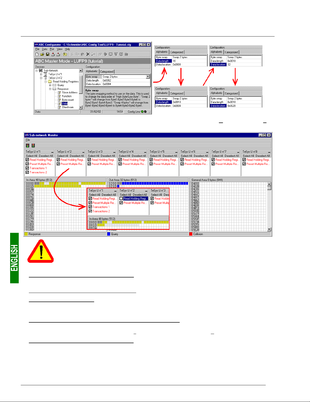
6. Configuring the Gateway
To check that these changes have been entered into the configuration, choose “Monitor” from the “SubNetwork” menu again:
In point 6), you shall make sure the values of the displayed parameters are the same as the
exchange sizes displayed in the “Sub-network Monitor.” In the current example, “In Area
48 bytes” imply that the “Input1” area begins at offset 0 (physical address 16#0000) and that
its length is equal to 48 bytes. Also, “Out Area 32 bytes” imply that the “Output1” area begins
at offset 0 (physical address 16#0200) and that its length is equal to 32 bytes.
4) Transferring this configuration to the gateway Please see chapter 6.4 Transferring a Configuration to the
Gateway, page 43. Check that the configuration is valid (LED s DEVICE STATUS flashing green).
5) Saving this configuration to your PC’s hard disk.
6) Checking the gateway setup: In RsNetWorx, check the values of the gateway parameters (see chapter 4.2.4
Editing gateway parameters, page 26). Only the value of parameter no. 7, “Input1 length”, should have
changed, from “32 bytes” to “48 bytes”.
7) Changing the amount of data received by the DeviceNet scanner: Still in RsNetWorx, change the value for
the amount of periodic data received by the DeviceNet scanner (see chapter 4.2.5 Configuring the DeviceNet
Scanner, page 28). Change the value of the “Rx Size:” field from 32 to 48, in the “P
8) Configuring the DeviceNet master PLC inputs: In RsNetWorx, establish a new correspondence between the
data from the gateway and the PLC inputs, according to the requirements of your application (see
chapter 4.2.6 Configuring Inputs from the Gateway, page 29). The various possibilities offered by RsNetWorx
for establishing a correspondence between the data from a DeviceNet subscriber and the PLC inputs will not
be covered here. Please see the documentation for this software application to find out more about this step
in setting up a DeviceNet master PLC.
52
olled:” section.

6. Configuring the Gateway
In this guide, we will be using the “AutoMap” command to establish a “raw” correspondence with all of the
data from the LUFP9 gateway. We then get the correspondence shown below, derived from the one used
with the gateway’s default configuration. The changes in relation to the default configuration are shown by a
greyed-out background, like the “free memory locations”.
Service PLC input
Managing the downstream Modbus
network
Periodic communications
—
Monitoring of
TeSys U motor starters
Aperiodic communications
—
Reading the value of a motor
starter parameter (
Aperiodic communications
Writing the value of a motor
starter parameter (
Aperiodic communications
(“Trigger bytes” for the responses)
Periodic communications
Monitoring of
TeSys U motor starter d
RESPONSE)
—
RESPONSE)
—
I:1.1
I:1.2
I:1.3
I:1.4
I:1.5
I:1.6
I:1.7
I:1.8
I:1.9
I:1.10
I:1.11
I:1.12
I:1.13
I:1.14
I:1.15
I:1.16
I:1.17
I:1.18
I:1.19
I:1.20
I:1.21
I:1.22
I:1.23
I:1.24
Description
......................Bit 7 Bit 8 ................... Bit 15
Bit 0
LUFP9 gateway status word
(MSB Æ 16#xx••) (LSB Æ 16#••xx)
Value of the motor starter c status register
Free memory location
Value of the motor starter e status register
Value of the motor starter f status register
Value of the motor starter g status register
Value of the motor starter h status register
Value of the motor starter i status register
Value of the motor starter j status register
Free memory location Slave no. (16#01-16#08)
Function number (16#03) Number of bytes read (16#02)
Value of the parameter read
(MSB Æ 16#xx••) (LSB Æ 16#••xx)
Slave no. (16#01-16#08) Function no. (16#06)
Address of the parameter written
(MSB Æ 16#xx••) (LSB Æ 16#••xx)
Value of the parameter written
(MSB Æ 16#xx••) (LSB Æ 16#••xx)
Read parameter
response counter
Value of the “TeSys U Status Register”
Value of the “Complementary Status Register”
Value of the “K7 Status Register”
Value of the “K7 Status Register 2 (free format)”
Value of the “K7 Status Register 3 (free format)”
Value of the “Warning Number” register
Value of the “Warning Register”
Value of “Reserved : 2nd Warning Register”
Write parameter
response counter
9) Transferring the DeviceNet scanner configuration: Following the changes made to the list of DeviceNet
scanner exchanges, it needs to be transferred to the DeviceNet scanner. Please see chapter 4.2.9
Transferring the DeviceNet Scanner Configuration, page 32.
6.8.4. Increasing the amount of periodic output data
E.g. “TeSys U n°4” motor starter. We are attempting to complete the control for this motor starter whilst retaining the
currently controlled “Command Register” (address 704 = 16#02C0), and adding the following next register, that is to
say “2st Command Register” (address 705 = 16#02C1). The number of registers controlled is therefore increased
from 1 to 2.
There are quite a lot of operations to be carried out. They are described in order below:
53

6. Configuring the Gateway
1) Changing the number of registers controlled: This step consists of changing the value of the “No. of
Registers” in the “Query” and in the “Response” for the “Preset Multiple Registers” command (Modbus
command for writing values of a number of registers). Start by selecting “Starting Address” from the “Query”,
then change its value as shown below. AbcConf will automatically convert any value entered in decimal to
hexadecimal.
checks the value of this field when it receives each Modbus response. If the value does not correspond to
that of the query, the gateway will ignore the response.
Do the same for the “Starting Address” element of the “Response” because the gateway
2) Changing the number of data bytes in the Modbus query: The number of bytes written into the memory of the
“TeSys U n°4” motor starter memory increases from 2 to 4, as the number of registers controlled has
increased from 1 to 2. Select the “Byte count” element from the “Query” and change its value as shown
below. AbcConf will automatically convert any value entered in decimal to hexadecimal.
54

6. Configuring the Gateway
3) Changing the location of the Modbus data transmitted into the gateway’s memory: As the number of bytes
written (see previous step) has increased from 2 to 4, the Modbus data to be transmitted to the “TeSys U n°4”
motor starter must be placed at a different location in the gateway’s memory, and the size of the memory
occupied must also be adjusted appropriately.
If you are not certain how much of the gateway’s memory is currently occupied, select “Sub-Network” and
choose “Monitor” from the “S
much of the gateway’s memory is occupied.
ub-Network” menu. The window shown below appears, allowing you to see how
To see which memory locations are occupied by data from the command you are interested in, all you have
to do is uncheck the box corresponding to the “Preset Multiple Registers” command from the “TeSys U n°4”
node, as shown above. We can see that the Modbus data transmitted with the query corresponding to this
command occupy 2 bytes located from address 16#0208.
Memory locations 16#0200 and 16#0201 are reserved (see chapter 5 Gateway Initialization and
Diagnostics, page 33). So you will not be able to place any Modbus data in these locations.
The sizes displayed above the graphics areas of this window (“In Area 32 bytes” and “Out Area
32 bytes”) correspond to the total input and ouput sizes you must check under RsNetWorx (see
point 6) on next page) and configure for the DeviceNet scanner (see point 7) ).
If you wish to place the 4 bytes of Modbus data which will be transmitted by the gateway for this command
into memory, once the changes have been made, we will have to move all the other output data by 2 bytes,
which may be tedious, or change the memory location of the block of data transmitted. In the example
described here, we will be using the second solution, although the first solution is actually preferable, in
principle, as it avoids leaving any “holes” in the gateway’s memory, thus optimising the transfer of all of the
data from the DeviceNet master PLC. Furthermore, the 1747-SDN scanner can only exchange 32 output
words with the master PLC. Leaving “holes” of this sort in the gateway’s memory is therefore not
recommended in cases of large configurations.
We will place the 4 bytes of data from address 16#0220 (544 in decimal).
data at even addresses in order to align the Modbus data (in 16-bit format) on the O:1.x outputs of the 1747SDN DeviceNet scanner.
Close the “Sub-network Monitor” window, then once you are back in the main AbcConf window, select the
“Data length” and “Data location” fields of the “Data” element from the “Query” one after another and change
their values as shown at the top of the next page. AbcConf will automatically convert any value entered in
decimal to hexadecimal.
N.B. As far as possible, place the
55

6. Configuring the Gateway
To check that these changes have been entered into the configuration, choose “Monitor” from the “SubNetwork” menu again:
In point 6), you shall make sure the values of the displayed parameters are the same as the
exchange sizes displayed in the “Sub-network Monitor.” In the current example, “In Area
32 bytes” imply that the “Input1” area begins at offset 0 (physical address 16#0000) and that
its length is equal to 32 bytes. Also, “Out Area 36 bytes” imply that the “Output1” area begins
at offset 0 (physical address 16#0200) and that its length is equal to 36 bytes.
4) Transferring this configuration to the gateway Please see chapter 6.4 Transferring a Configuration to the
Gateway, page 43. Check that the configuration is valid (LED s DEVICE STATUS flashing green).
5) Saving this configuration to your PC’s hard disk.
6) Checking the gateway setup: In RsNetWorx, check the values of the gateway parameters (see chapter 4.2.4
Editing gateway parameters, page 26). Only the value of parameter no. 19, “Output1 length”, should have
changed, from “32 bytes” to “36 bytes”.
7) Changing the amount of data transmitted by the DeviceNet scanner: Still in RsNetWorx, change the value for
the amount of periodic data transmitted by the DeviceNet scanner (see chapter 4.2.5 Configuring the
DeviceNet Scanner, page 28). Change the value of the “Tx Size:” field from 32 to 36, in the “P
56
olled:” section.

6. Configuring the Gateway
8) Configuring the DeviceNet master PLC outputs: In RsNetWorx, establish a new correspondence between the
data transmitted to the gateway and the PLC outputs, according to the requirements of your application (see
chapter 4.2.7 Configuring Outputs Intended for the Gateway, page 30). The various possibilities offered by
RsNetWorx for establishing a correspondence between the data transmitted to a DeviceNet subscriber and
the PLC outputs will not be covered here. Please see the documentation for this software application to find
out more about this step in setting up a DeviceNet master PLC.
In this guide, we will be using the “AutoMap” command to establish a “raw” correspondence with all of the
data transmitted to the LUFP9 gateway. We then get the correspondence shown below, derived from the one
used with the gateway’s default configuration. The changes in relation to the default configuration are shown
by a greyed-out background, like the “free memory locations”.
Service PLC output
Managing the downstream Modbus
network
Periodic communications
—
Controlling
TeSys U motor starters
Aperiodic communications
—
Reading the value of a
motor starter parameter (Q
Aperiodic communications
—
Writing the value of a
motor starter parameter (Q
Aperiodic communications
(“Trigger bytes” for the queries)
Periodic communications
Monitoring of TeSys U motor starter f
UERY)
UERY)
O:1.1
O:1.2
O:1.3
O:1.4
O:1.5
O:1.6
O:1.7
O:1.8
O:1.9
O:1.10
O:1.11
O:1.12
O:1.13
O:1.14
O:1.15
O:1.16
O:1.17
O:1.18
Description
Bit 0
......................Bit 7 Bit 8 ................... Bit 15
DeviceNet master command word
(MSB Æ 16#xx••) (LSB Æ 16#••xx)
Value of the motor starter c command register
Value of the motor starter d command register
Value of the motor starter e command register
Free memory location
Value of the motor starter g command register
Value of the motor starter h command register
Value of the motor starter i command register
Value of the motor starter j command register
Slave no. (16#01-16#08) Function no. (16#03)
Address of the parameter to be read
(MSB Æ 16#xx••) (LSB Æ 16#••xx)
Number of parameters to be read
(MSB Æ 16#00••) (LSB Æ 16#••01)
Slave no. (16#01-16#08) Function no. (16#06)
Address of the parameter to be written
(MSB Æ 16#xx••) (LSB Æ 16#••xx)
Value of the parameter to be written
(MSB Æ 16#xx••) (LSB Æ 16#••xx)
Read parameter
query counter
Value of the “Command Register”
Value of the “2nd Command Register”
Write parameter
query counter
9) Transferring the DeviceNet scanner configuration: Following the changes made to the list of DeviceNet
scanner exchanges, it needs to be transferred to the DeviceNet scanner. Please see chapter 4.2.9
Transferring the DeviceNet Scanner Configuration, page 32.
57
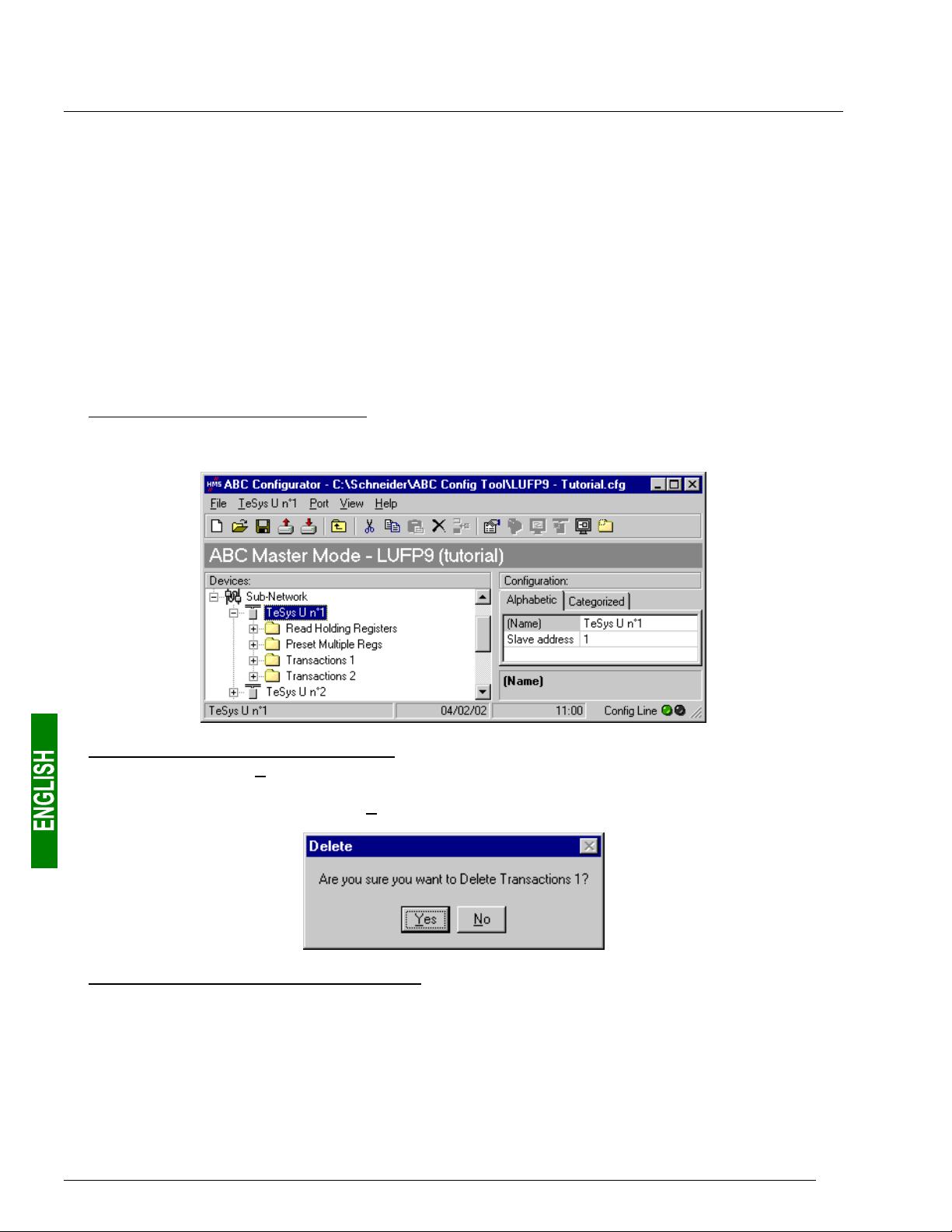
6. Configuring the Gateway
6.9. Deleting Aperiodic Parameter Data
If your PLC application does not need the aperiodic service for reading/writing parameter data on Modbus
slaves, you can delete the associated commands. If you also intend to add Modbus data, and therefore use new
locations in the gateway’s memory, it is preferable to delete the aperiodic commands from the start, so that you
can reuse the memory locations.
On the other hand, if the only configuration operation you wish to carry out on the LUFP9 gateway consists of
not using the aperiodic service for parameter data, you can simply not use this service in RsNetWorx. Go
straight on to step 8). In fact the Modbus exchanges associated with this setup will not be carried out if the
associated data is not changed by the DeviceNet master PLC. So deleting associated Modbus commands
becomes optional.
The operations you will need to carry out are described in order below:
1) Displaying parameter data commands: Select the very first node of the downstream Modbus network,
“TeSys U n°1”, and expand the tree structure showing its commands and transactions. The screen should
look like the one below:
2) Deleting the read command for a parameter: Select the personalized “Transactions 1” command and delete it
with the “Del” key (or “Delete” from the menu whose name corresponds to the name of the selected node).
A request for confirmation appears, asking you whether or not to proceed deleting the “Transactions 1”
command. In this case confirm with the “Yes” button.
3) Deleting the write command for a parameter: Back in the main AbcConf window, the “Transactions 1”
command has been deleted. The second personalised command, “Transactions 2” is automatically renamed
“Transactions 1”, but retains all of its setup. Now delete this one in the same way as you did with the previous
command.
58

6. Configuring the Gateway
4) Checking the new memory occupation: If you wish to check how much of the gateway’s memory is now
occupied, select “Sub-Network” and choose “Monitor” from the “Sub-Network” menu. The following window
appears, allowing you to see how much of the gateway’s memory is occupied by Modbus data. The part
framed in red represents the memory occupation before the deletion of the two setup commands. It has been
inlaid in the illustration below so that you can see the effects of the deletion operations we have just carried
out.
You will note that the “TeSys U n°1” section now only has the two Modbus commands common to the eight
TeSys U motor starters, and that the memory locations which corresponded to the two personalised
commands are now free.
N.B. The free memory location at address 16#0012 in the gateway’s memory is no longer part of the
gateway’s inputs, because there is no input data used beyond this address.
5) Transferring this configuration to the gateway Please see chapter 6.4 Transferring a Configuration to the
Gateway, page 43. Check that the configuration is valid (LED s DEVICE STATUS flashing green).
6) Saving this configuration to your PC’s hard disk.
7) Checking the gateway setup: In RsNetWorx, check the values of the gateway parameters (see chapter 4.2.4
Editing gateway parameters, page 26). The value of parameter no. 7, “Input1 length”, should have changed,
from “32 bytes” to “18 bytes”. The value of parameter no. 19, “Output1 length”, should have changed, from
“32 bytes” to “18 bytes”.
8) Changing the amount of data received and the amount of data transmitted by the DeviceNet scanner: Still in
RsNetWorx, change the value for the amount of periodic data received and the amount of periodic data
transmitted by the DeviceNet scanner (see chapter 4.2.5 Configuring the DeviceNet Scanner, page 28). In
the “Polled:” section, change the value of the “Rx
field from 32 to 18.
9) Configuring the DeviceNet master PLC inputs and outputs: In RsNetWorx, establish a new correspondence
between the data from the gateway and the PLC inputs (see chapter 4.2.6 Configuring Inputs from the
Gateway, page 29). Do the same for the correspondence between the data transmitted to the gateway and
the PLC outputs (see chapter 4.2.7 Configuring Outputs Intended for the Gateway, page 30).
Size:” field from 32 to 18 and the value of the “Tx Size:”
We then get the two correspondences shown on the next page, derived from those used with the gateway’s
default configuration.
59

6. Configuring the Gateway
Service PLC input
Managing the downstream Modbus
network
Periodic communications
—
Monitoring of
TeSys U motor starters
Service PLC output
Managing the downstream Modbus
network
Periodic communications
—
Controlling
TeSys U motor starters
I:1.1
I:1.2
I:1.3
I:1.4
I:1.5
I:1.6
I:1.7
I:1.8
I:1.9
O:1.1
O:1.2
O:1.3
O:1.4
O:1.5
O:1.6
O:1.7
O:1.8
O:1.9
Description
..................... Bit 7 Bit 8....................Bit 15
Bit 0
LUFP9 gateway status word
(MSB Æ 16#xx••) (LSB Æ 16#••xx)
Value of the motor starter c status register
Value of the motor starter d status register
Value of the motor starter e status register
Value of the motor starter f status register
Value of the motor starter g status register
Value of the motor starter h status register
Value of the motor starter i status register
Value of the motor starter j status register
Description
Bit 0
..................... Bit 7 Bit 8....................Bit 15
DeviceNet master command word
(MSB Æ 16#xx••) (LSB Æ 16#••xx)
Value of the motor starter c command register
Value of the motor starter d command register
Value of the motor starter e command register
Value of the motor starter f command register
Value of the motor starter g command register
Value of the motor starter h command register
Value of the motor starter i command register
Value of the motor starter j command register
10) Transferring the DeviceNet scanner configuration: Following the changes made to the list of DeviceNet
scanner exchanges, it needs to be transferred to the DeviceNet scanner. Please see chapter 4.2.9
Transferring the DeviceNet Scanner Configuration, page 32.
6.10. Changing a Modbus slave Configuration
Configuring a Modbus slave itself remains very simple because it only involves the name and the Modbus
address of the node to which it corresponds. On the contrary, configuring Modbus commands is much more
complete and is the subject of a separate object of its own (see chapter 6.11 Adding and Setting Up a Modbus
Command, page 62).
You will need to change the configuration of a Modbus slave when you add a new Modbus unit (see chapter 6.7
Adding a Modbus Slave, page 46), using any method.
Changing the name of the node which corresponds to a Modbus slave is used to distinguish it from the other
nodes when the configuration of its Modbus commands has been changed, for instance.
6.10.1. Changing the Name of a Modbus Slave
To carry out this operation, all you have to do is select the node which corresponds to the Modbus slave involved
(“Devices:” section), click on the current name (value of the “(Name)” field, in the “Configuration:” section), then
change it. After confirming the new name (“
become effective in AbcConf, and the name of the node will be automatically updated in the “Devices:” section.
An example is given at the top of the next page. The three red frames shown in this example show the
consequences of the change made.
Enter” key or click outside the name’s data entry field), this will
60

6. Configuring the Gateway
6.10.2. Changing the Address of a Modbus Slave
To carry out this operation, all you have to do is select the node which corresponds to the Modbus slave involved
(“Devices:” section), click on the value of the current address (value of the “Slave address” field, in the
“Configuration:” section), then change it.
Reminder: The address of a Modbus slave must be between 1 and 247.
If you use Modbus slaves belonging to the Schneider Electric Speed Variation range, such as
Altistarts or Altivars, do not configure
Modbus network as these products, because these addresses are reserved when using these
products.
After confirming the new address (“
Modbus slave), this will become effective in AbcConf, and the values of the “Slave Address” elements of the
queries and responses in the Modbus commands for the selected node will be automatically updated. An
example is given below, but the updating of a single “Slave Address” element is shown:
Enter” key or click outside the data entry field of the address of the
ANY slaves at the addresses 65, 126 or 127 on the same
61
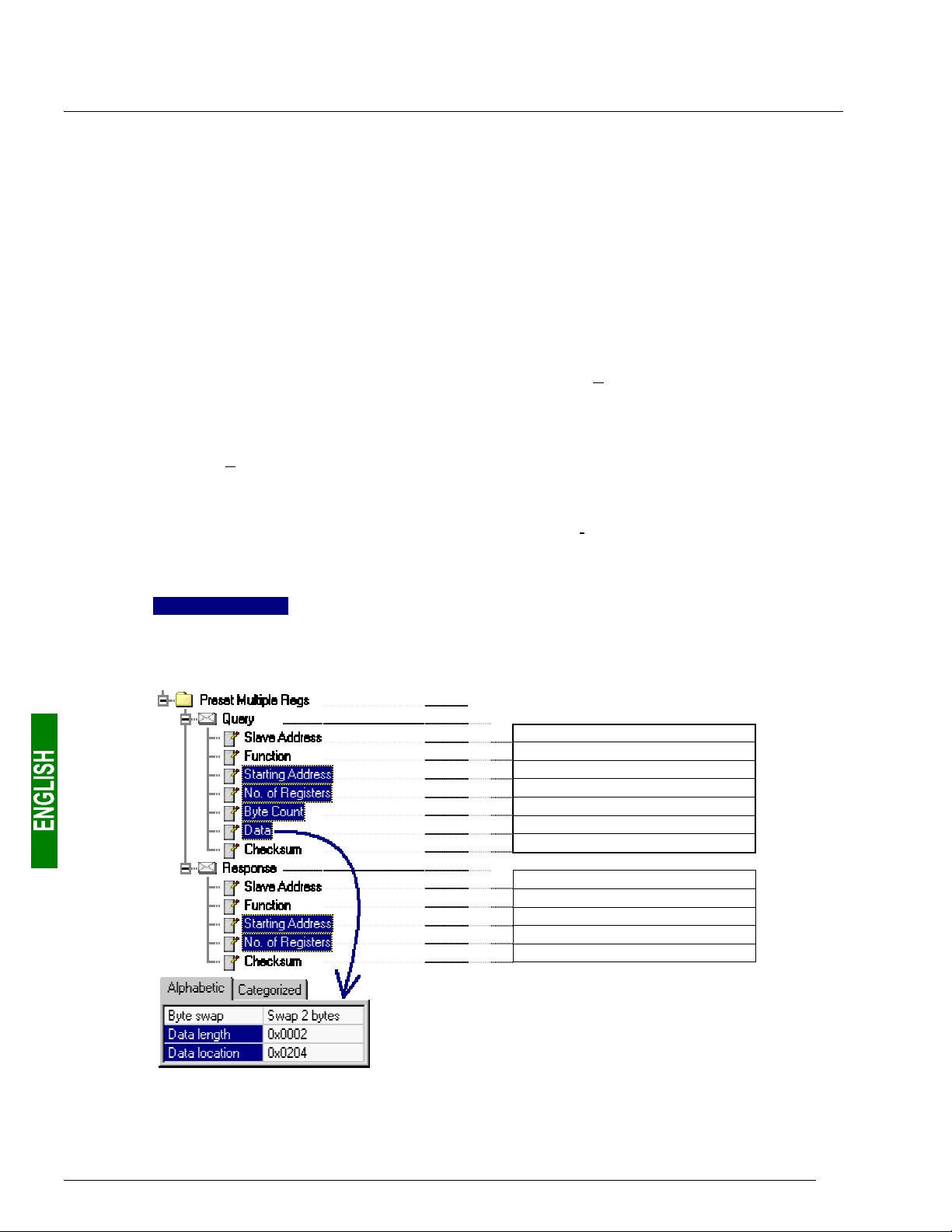
6. Configuring the Gateway
y
)
)
)
)
)
)
6.11. Adding and Setting Up a Modbus Command
6.11.1. With TeSys U Motor Starters
With TeSys U motor starters, the main use of adding a Modbus command consists of allowing you to control or
monitor additional registers, without having to change the elements in the default configuration. So, the operation
of the periodic and aperiodic communication services remains the same as for the default configuration, unlike
the operations described in the various parts of chapter 6.8 Changing the Periodic Data Exchanged With a
Modbus Slave, page 48.
Instead of adding a command and fully configuring it, it is a better idea to copy one of the two default commands
for TeSys U motor starters, “Read Holding Registers” (reading/monitoring) or “Preset Multiple Registers”
(writing/controlling), and to paste it into the list of Modbus commands for the appropriate node.
To copy an already configured Modbus command, select it, then choose “Copy” from the menu whose name
corresponds to the name of the selected command. Keyboard shortcut: “Ctrl C”. Then continue using one
of the two methods shown below:
a) Select the node corresponding to the Modbus slave for which you wish to add this command (e.g. “TeSys U
n°4”), then choose “Paste” from the menu whose name corresponds to the selected node. A new command is
added after all the other configured commands for this node. The whole of its configuration is identical to that
for the previously copied command.
b) Select one of the commands for the node involved, then choose “Insert” from the menu whose name
corresponds to the selected command. A new command is added just before the one which is selected. The
whole of its configuration is identical to that for the previously copied command.
Keyboard shortcut: “Ctrl V”.
As the new Modbus command and the original Modbus command are identical, you will need to make changes
to the fields
Multiple Registers” command or a “Read Holding Registers” command (see chapter 6.8 Changing the Periodic
Data Exchanged With a Modbus Slave, page 48). The correspondence between the various elements which
appear in these tree structures and the standard Modbus terminology is located to their right:
highlighted in blue in one of the two following diagrams, depending on whether this is the “Preset
Name of the Modbus command
Modbus quer
Slave no.
Function no.
No. of the 1st word(MSB / LSB
Number of words (MSB / LSB
Numberof bytes
…Values of the words(MSB/LSB)…
CRC16 (LSB / MSB
Modbus response ! Frame "
Slave no.
Function no.
No. of the 1st word(MSB / LSB
Number of words (MSB / LSB
CRC16 (LSB / MSB
! Frame "
62

6. Configuring the Gateway
y
)
)
)
)
Name of the Modbus command
Modbus quer
Slave no.
Function no.
No. of the 1st word (MSB / LSB
Number of words (MSB / LSB
CRC16 (LSB / MSB
Modbus response ! Frame "
Slave no.
Function no.
Numberof bytes read
…Values of the words (MSB/LSB)…
CRC16 (LSB / MSB
N.B. In all cases, the “Query / Slave Address” and “Response / Slave Address” elements are automatically
updated by AbcConf according to the node in which the command is located. Their values cannot be changed by
the user. In the same way, the “Query / Function” and “Response / Function” fields depend on the nature of the
Modbus command and cannot be changed by the user.
! Frame "
The operations to be carried out are more or less the same as those consisting of changing the default
commands. For the “Read Holding Registers” command, please see chapter 6.8.1 Replacing a Periodic Input
Data Element, page 48, and chapter 6.8.3 Increasing the Amount of Periodic Input Data, page 50. For the
“Preset Multiple Registers” command, please see chapter 6.8.2 Replacing an Output Periodic Data Element,
page 49, and chapter 6.8.4 Increasing the amount of periodic output data, page 53.
6.11.2. With a Generic Modbus Slave
Unlike the previous chapter, here we will be looking at adding and setting up a Modbus command which is
different from those configured by default with the LUFP9 gateway. We will benefit from this occasion to
exhaustively describe the fields allowing you to set up the management of communications for a command of
this sort.
Please see chapter 11 Appendix E: Modbus Commands, page 113, for a list of the Modbus functions supported
by the LUFP9 gateway. If you need to use a command which is not supported by the gateway, you can configure
one. A command of this sort is included in a specific element called “Transactions” or becomes a new Modbus
command in its own right. Please see the next chapter, § 6.11.3 Adding a Special Modbus Command, page 73,
for further details on this subject.
E.g. To illustrate the various operations to be carried out and the explanations given, we will be taking the
example of a Altistart starter, the ATS48, and a Modbus command recognised both by the gateway and the
ATS48. This is the “Preset Single Register” command, whose function code is 6 and which allows you to write
the value of a unique output word. This function will be used to periodically write the value of the ATS48’s CMD
command register, located at address W400 (address 400 = 16#0190).
Since the gateway’s default configuration already has 8 Modbus slaves, you will need to delete one of them,
such as the “TeSys U n°2” node, for example, and to add a new node in its place (see chapter 6.6 Deleting a
Modbus Slave, page 45, and chapter 6.7 Adding a Modbus Slave, page 46).
not to delete the “TeSys U n°1” node, as it contains the commands corresponding to the read and write services
for a parameter in a Modbus slave.
Reminder: We strongly advise you
63

6. Configuring the Gateway
y
)
)
)
)
)
)
We rename the “New Node”,
which has just been created, in
“ATS48”, and we assign it the
Modbus address 10, as shown
here:
We then proceed to add the
“Preset Single Register”
command by choosing “Add
Command” from the “A
menu.
TS48”
In the window which appears (shown opposite), select the “0x06 Preset
Single Register” command and choose “Select” from the “F
Back in the main AbcConf window, the “Preset Single Register” command
now appears in the list of Modbus commands for the “ATS48” node.
ile” menu.
Expand the full tree structure for this command, shown below. The correspondence between the various elements
which appear in this tree structure and the standard Modbus terminology is located to its right.
Name of the Modbus slave
Name of the Modbus command
Modbus quer
Slave no.
Function no.
Word no. (MSB / LSB
Value of the word (MSB / LSB
CRC16 (LSB / MSB
Modbus response ! Frame "
Slave no.
Function no.
Word no. (MSB / LSB
Value of the word (MSB / LSB
CRC16 (LSB / MSB
These elements can be configured using AbcConf. There is a description of them in the following chapters. We
will then return to the example of the ATS48 to illustrate how to use these elements.
! Frame "
64

6. Configuring the Gateway
6.11.2.1. Managing Degraded Modes
Due to the number of hardware elements and software tools used, the following table shows a summary of the
various degraded modes in a DeviceNet application. In this case, this application includes an LUFP9 gateway,
but we will not be including either the master PLC or its scanner:
Event
Disconnection
of the downstream
Modbus RTU
network (1) (2)
——
“Offline options for sub-
network” = “Clear”
“Offline options for sub-
network” = “Freeze”
Desired behaviour
Outputs
Inputs
Reset
Hold
Stop refresh
Reset
Hold
DeviceNet PLC:
CPU stop or failure
Depending on the
configuration
of the DeviceNet
master
——
——
——
Disconnection of the
upstream DeviceNet
network (1)
“Offline options for
fieldbus” = “Clear”
“Offline options for
fieldbus” = “Freeze”
“Offline options for
fieldbus” = “No Scanning”
Depending on the configuration
of the DeviceNet master
Failure of the
LUFP9 gateway
(2)
Depending on the configuration
of the Modbus slaves
(1) The “Offline options for fieldbus” and “Offline options for sub-network” are described in the next chapter.
(2) The behaviour desired with regard to the outputs should be directly configured on each of the Modbus
slaves. In the case of drives marketed by
Schneider Electric, for instance, resetting the outputs is
configured by setting the NTO bit to 0 (communication control), and they are held by setting NTO to 1
(suppression of communication control).
You can also read the user manuals for your master and your DeviceNet scanner to obtain further details about
how to process degraded modes.
65

6. Configuring the Gateway
6.11.2.2. Configuring the Query
Select the “Query” element from the Modbus command. The
various elements of the configuration of the query for this command
are shown opposite. The values displayed correspond to the
default values for any new command.
These elements allow you to configure how the whole command is
managed, including how degraded modes are managed (number of
re-transmissions, for example).
Each of these elements is described, in order, in the table below. When a unit is assigned to an element, it is
shown in brackets after the name of the element:
Configuration
element
Minimum time
between
broadcasts
(10ms)
Offline options
for fieldbus
Offline options
for sub-network
Reconnect time
(10ms)
Description
This element is only relevant if you have added a “Broadcaster” node (see chapter 6.13
Adding a Broadcaster Node, page 79). This parameter then allows you to specify a waiting
time following the transmission of the selected broadcast command. The next Modbus
message, whatever it is, will only be transmitted by the gateway once this time has elapsed.
So it needs to be long enough to allow the slowest Modbus slave to process the command
which has been broadcast. This parameter is not used by commands which do not belong
to a broadcaster node.
With the LUFP9 gateway’s default configuration, this feature has not been used, so as to
control the Modbus slaves individually.
This element affects the data sent to the Modbus slave, but only in the query to which this
element belongs to, whenever the gateway is disconnected from the DeviceNet network. This
element takes one of the following three values:
- Clear ............. From now on all data sent to the Modbus slave using this query is set to
16#0000 (resetting of the output data in the gateway’s memory).
- Freeze........... All data sent to the Modbus slave using this query retains its current values
(the output data in the gateway’s memory is frozen).
- NoScanning .. The query is no more transmitted to the Modbus slave by the gateway.
This element affects the data sent to the DeviceNet master PLC whenever the query to
which this element belongs to has not been answered with a response by the Modbus slave
(no response). This element takes one of the following two values:
- Clear ............. From now on the data sent to the DeviceNet master PLC is set to 16#0000
(resetting of the input data in the gateway’s memory).
- Freeze........... From now on the data sent to the DeviceNet master PLC retains its current
values (the input data in the gateway’s memory is frozen).
N.B. exception responses issued by the Modbus slaves do not trigger the use of these “Offline options!”
If there is no response from the Modbus slave to a query, or following the receipt of an
incorrect response, the gateway uses the “Retries” and “Timeout time (10ms)” elements to
carry out re-transmissions. If the Modbus slave has still not responded correctly following
these re-transmissions, the gateway stop sending it the corresponding query for a period of
time which can be adjusted using “Reconnect time (10ms)”.
When this period is over, the gateway attempts to restore communication with the Modbus
slave.
66

6. Configuring the Gateway
Configuration
element
Retries This element indicates the number of re-transmissions carried out by the gateway if there is
Timeout time
(10ms)
Trigger byte
address
Description
no response from the Modbus slave to a query, or if the response is incorrect. This retransmission process ceases as soon as the gateway gets a correct response within a given
time. If none of the re-transmissions has allowed the gateway to obtain a correct response,
the Modbus slave is deemed to be off-line, but only in relation to the command in question.
The gateway then uses the “Offline options for sub-network” and “Reconnect time (10ms)”
elements and the LED
if the Modbus command is answered with a correct response, once the reconnection has
started (see element “Reconnect time (10ms)”).
If the number of re-transmissions is set to 0, the process described above will not be run.
This element represents the time that the Modbus slave will wait for a response. If a
response has not reached the gateway within the given time, configured using the “timeout
time (10ms)” element, the gateway proceeds to a re-transmission. This process continues
until it reaches the last re-transmission allowed (see “Retries”), then the gateway declares
the Modbus slave off-line, but only for the command to which the “timeout time (10ms)”
belongs to.
This element is only used by the gateway if “Update mode” is set to “Change of state on
trigger”. In this case, it specifies the address, in the gateway’s output memory (16#0202 to
16#03FF), of an 8-bit counter managed by the DeviceNet master.
When the value located at this address is changed by the DeviceNet master but
from zero
transmitted to the Modbus slave. So the DeviceNet master must have access to this counter
in the same way as for the periodic output registers sent to TeSys U motor starters.
In comparison to the “On data change” mode, this mode allows you to send a command on
a specific order from the DeviceNet master if, for example, the latter is unable to update all
data of any given query at the same time.
, the query configured with a “Change of state on trigger” related to this address is
r MODBUS becomes red. This LED will only revert to a green state
different
N.B. In the specific case of the gateway’s default configuration, the “Transactions 1” and
“Transactions 2” personalized command mode for the “TeSys U n°1” node is set to “Change
of state on trigger”. These aperiodic commands are respectively used to read and write the
value of a parameter for one of the Modbus slaves.
The “Trigger byte address” elements of the “Query” elements for these two commands are
configured at addresses 16#021E and 16#021F. These are the “parameter read/write
request counters”. Considered under DeviceNet and RSNetWorx, these two data are
configured the same way as the other outputs (see chapter 4.2.7 Configuring Outputs
Intended for the Gateway, page 30) and both correspond to the O:1.16 output.
To transmit one of these two commands, the DeviceNet master PLC must first of all update
all of the data to be transmitted on the Modbus network for this command (addresses
16#0212 to 16#0217 or addresses 16#0218 to 16#021D), then change the value of the
associate counter (address 16#021E or 16#021F). The gateway will then transmit the query
corresponding to the command.
N.B. The “trigger byte” does not have to be an item of output data updated by the
DeviceNet master. In fact it is quite possible that it may be an input between 16#0002 and
16#01FF. In this case, the Modbus slave which updates this byte will condition the
exchanges of the command you’re currently configuring.
67

6. Configuring the Gateway
Configuration
element
Update mode This element is used to specify the transmission mode for the query on the Modbus
Update time
(10ms)
Description
network. It takes one of the following four values:
- Cyclically................................. Default communication mode. The query is transmitted
periodically on the Modbus network (see “Update time”).
- On data change ...................... The gateway transmits the query on the Modbus network
when at least one item of data from this query is changed by the DeviceNet master.
So this is an
- Single Shot ............................. This transmission mode only allows a single Modbus
exchange for the whole of the time that the gateway is operating. This exchange
takes place just after the initialization of the gateway.
- Change of state on trigger ...... With this
query is sent every time that the DeviceNet master changes the value of an 8-bit
counter designated by the “Trigger byte address” element. For instance, this is the
case with the queries associated with “Transactions 1” and “Transactions 2”
personalized commands for the “TeSys U n°1” node of the gateway’s default
configuration. These queries are transmitted when the values of the related “trigger
bytes” (addresses 16#021E and 16#021F) are changed by the DeviceNet master.
Please see the description of this element for further information about how to use
this communication mode.
This element is only used by the gateway if “Update mode” is set to “Cyclically”. In this case, it
specifies the query’s transmission period on the Modbus network.
aperiodic communication mode.
aperiodic communication mode, the Modbus
e.g. With the ATS48, we will be using the configuration shown
opposite. The most notable points of this configuration are:
• On disconnection the data is reset on one of the two networks.
• 3 re-transmissions with a 100 ms timeout.
• Periodic communications with a cycle time set to 300 ms.
68

6. Configuring the Gateway
6.11.2.3. Configuring the Response
Next select the “Response” element from the Modbus command.
The various elements of the configuration of the response for this
command are shown opposite. The values displayed correspond to
the default values for any new command.
These elements allow you to configure a single aspect of managing the command, described at the top of the
page on the right. Each of these elements is described, in order, in the table below.
Configuration
element
Trigger byte
Trigger byte
address
Description
This element is used by the gateway to activate the unitary incrementation of an 8-bit
counter in order to notify the DeviceNet master of the receipt of a new response to the
associated Modbus command. It takes one of the following two values:
- Disabled.................................. Default configuration. The gateway does not increment any
counter on receipt of the Modbus response.
- Enabled .................................. Each time that the gateway receives a new response to the
associated Modbus command, it increments the value of an 8-bit counter designated
by the “Trigger byte address” element (see below). If used, this counter allows the
DeviceNet master, for example, to only consider the response’s corresponding data
when this counter’s value is incremented.
This element is only used by the gateway if the element “Trigger byte” is set to “Enabled”. In
this case, it specifies the address, in the gateway’s input memory (16#0002 to 16#0002), of
an 8-bit counter managed by the gateway.
When the gateway receives a response to the associated Modbus command, it increments
the value of this counter in a unitary manner (value = value+1). So the DeviceNet master
must have access to this counter in the same way as for the periodic input registers from
the TeSys U motor starters.
This mode allows the DeviceNet master to be informed that a new response is available.
This can be useful, for example, if it is possible that the data from two consecutive
responses may be identical.
N.B.: In the specific case of the gateway’s default configuration, the “Trigger byte” element
for responses to the “Transactions 1” and “Transactions 2” personalized commands of the
“TeSys U n°1” node is set to “Enabled”. Hence, the management of responses to read and
write commands for parameters is
The “Trigger byte address” elements of the “Response” elements for these two commands
are configured at addresses 16#001E and 16#001F. These are the “parameter read/write
response counters”. Considered under DeviceNet and RSNetWorx, these two data are
configured the same way as the other inputs (see chapter 4.2.6Configuring Inputs from the
Gateway, page 29) and both correspond to the I:1.16 input.
The DeviceNet master PLC will be able to detect the receipt of a response from a Modbus
slave by comparing the previous value and the current value of the associated counter
(address 16#001E or 16#001F). If there is a
may, for example, read all of the data from the response (addresses 16#0013 to 16#0017
or addresses 16#0018 to 16#001D) and allow the transmission of a new query for reading
or writing the value of a parameter (using a “Trigger byte” for the queries). Contrarily to the
counter one can associate to the queries of any command, a response’s “Trigger byte” is a
true modulo 256 counter,
i.e. zero must be managed (… 254, 255, 0, 1, 2 …).
event driven.
unitary incrementation of this counter, the PLC
E.g. With the ATS48, we do not want the response to be event driven. So we will be retaining the default
configuration.
69

6. Configuring the Gateway
6.11.2.4. Configuring the Content of the Query Frame
The window shown below is obtained using “Edit Frame” from the “Query” menu. Unlike the tree structure in the
main AbcConf window, this display has the advantage of showing all of the frame’s fields at the same time as well
as their values. The values displayed below correspond to the values assigned by default to the Modbus command
query we have created. The correspondence with the content of the corresponding Modbus frame has been added
underneath this window.
Slave no. Function no.
Edit the values which are not greyed out, one after another. There is a description of them below.
The nature of a frame’s fields depends on the Modbus command to which it corresponds. However, a certain
number of these fields are common to all frames, whereas others are common to a number of them. Here is a
description of those shown above, for the example described at the beginning of the chapter 6.11.2:
Field in the
frame
Slave
Address
Function 1 byte This field cannot be changed by the user and its value is greyed out to inform
Register 2 bytes
Size in the
frame
1 byte This field cannot be changed by the user and its value is greyed out to inform
Word number
(MSB / LSB)
Description
him of the fact. AbcConf updates the value of this field automatically using the
address of the Modbus slave corresponding to the current node.
N.B. This field is common to queries for all Modbus commands.
E.g. The value of this field is set to the address of the Modbus slave which
corresponds to the “ATS48” node, that is to say 16#0A.
him of the fact. AbcConf updates the value of this field automatically using the
function code for the corresponding Modbus command.
N.B. This field is common to queries for all Modbus commands.
E.g. The value of this field is set to the code for the “Preset Single Register”
command (writing the value of an output word), that is to say 16#06.
Address of an output word, or of a register, in the Modbus slave’s memory. So this
field designates the memory object to which the command relates.
N.B. This field is common to queries for all Modbus commands whose purpose
is to access one or more locations in the memory of a Modbus slave. When
accessing several memory locations, the “Register” field designates the
address of the first word affected by the command.
E.g. The value of this field should be changed by entering the address of the
CMD command register, that is to say 400 (16#0190). This value will be
automatically converted to hexadecimal if the user enters it in decimal.
Value of the word (MSB / LSB) CRC16 (LSB / MSB)
70

6. Configuring the Gateway
Field in the
frame
Preset Data 2 bytes
Size in the
frame
or more for a
block of data
Description
Data Location: Address, in the gateway’s output data memory (16#0202 to
16#03FF), of the item of data to be transmitted in the “Preset Data” field for the
query’s frame.
N.B. The “Data location” field is used for each frame that allows you to
exchange some data between the Modbus slaves and the DeviceNet master.
In this case it designates the starting address of the block of data to be
transmitted.
N.B. As far as possible, ensure that the data is located at even addresses in
order to align the Modbus data (in 16-bit format) on the O:1.x outputs of the
DeviceNet scanner.
E.g. The value to be assigned to the ATS48’s CMD register should be placed
in the gateway’s output data memory area. We will be using the first free
location starting at an even address, that is to say the one located at 16#0220,
with the gateway’s default configuration.
Data length: Length of the block of output data, in the gateway’s memory,
whose values must be transmitted in the “Preset Data” field of the query’s
frame. It is expressed in number of bytes.
N.B. The “Data length” field is always used together with the “Data location”
field, described above.
E.g. Since the “Preset Single Register” command is used to write the value of a
single register (16-bit), the value of the “Data length” field must be set to 2.
See the documentation for each Modbus slave to find out the maximum
amount of 8-bit data which can be placed in “Data” type fields in queries and
responses for this slave. With the ATS48, for instance, it is limited to 30 16-bit
words.
Byte swap: Specifies whether the output data bytes to be transmitted to the
Modbus slave must be swapped before being placed in the Modbus frame or
not. The three possible values are as follows:
- No swapping ....... Default configuration. The data is sent in the same order as
they appear in the gateway’s memory.
- Swap 2 bytes ......The bytes to be transmitted are swapped two by two.
is the case which must be used by default
data, the most significant byte is placed first in the Modbus frame, whereas
it is always written into the gateway’s memory by a DeviceNet master with
the least significant byte first.
- Swap 4 bytes ......The bytes to be transmitted are swapped four by four. This
is rarely used, as it only relates to 32-bit data. The principle is similar to that
of the previous case, “Swap 2 bytes”.
E.g. We will be using the “Swap 2 bytes” value, because the two bytes of the
value to be written into the ATS48’s CMD register, as transmitted by the
SLC500 PLC, are placed into the gateway’s memory in least significant / most
significant order.
, because for an item of 16-bit
This
71

6. Configuring the Gateway
Field in the
frame
Checksum 2 bytes Error check type: Type of error check for the frame.
6.11.2.5. Configuring the Content of the Response Frame
The window shown below is obtained using “Edit Frame” from the “Response” menu. The values shown in it
correspond to the values assigned by default to the Modbus command response we have created. The
correspondence with the content of the corresponding Modbus frame has been added underneath this window.
Size in the
frame
Description
- CRC.....................Default method. This is the method adopted for the Modbus
RTU protocol.
- LRC .....................This method relates to the Modbus ASCII protocol. So it
should not be used in this case.
- XOR.....................Simple “OR Exclusive” applied to the frame’s bytes.
E.g. The LUFP9 gateway is specifically designed for the Modbus protocol RTU
mode.
Error check start byte: Indicates the number of the byte, in the frame, from
which the calculation of the “checksum” should begin. The first byte in each
frame carries the number 0.
E.g. The calculation of a frame’s checksum should always begin with the first
byte.
The default value, “CRC”, should not be changed.
The value of this field should therefore remain set to zero.
Slave no. Function no.
Edit the values which are not greyed out, one after another.
There is a description of them on the next page, but also see the previous chapter, as the nature of the content
of response frames is very similar to that of the fields in Modbus query frames.
If the value of a field from the response of a Modbus slave is different from that configured via
AbcConf, the response will be rejected by the gateway. It will then proceed to a re-transmission
of the query, provided that at least one re-transmission has been configured for this command
(see chapter 6.11.2.2 Configuring the Query, page 66). Of course, this remark does not relate to
the data itself, that is to say the Modbus frame fields configured using the “Data location,” “Data
length,” and “Byte swap” elements.
72
Word number
(MSB / LSB)
Value of the word (MSB / LSB) CRC16 (LSB / MSB)

6. Configuring the Gateway
Field in the
frame
Slave Address 1 byte Identical to that of the query’s “Slave Address” field.
Function 1 byte Identical to that of the query’s “Function” field.
Register 2 bytes
Preset Data 2 bytes
Checksum 2 bytes Error check type: Identical to that of the query’s “Error check type” field.
Size in the
frame
or more for a
block of data
Description
Identical to that of the query’s “Register” field, since the Modbus response of
any “Preset Single Register” command is an echo to the corresponding query.
Here you should also enter the address of the memory object to which the
command relates.
E.g. Enter the value 400, converted to 16#0190 by AbcConf.
Data Location: Address, in the gateway’s input data memory (16#0002 to
16#01FF), of the item of data received in the “Preset Data” field for the
response’s frame.
N.B. As far as possible, ensure that the data is located at even addresses in
order to align the Modbus data (in 16-bit format) on the I:1.x inputs of the
DeviceNet scanner.
E.g. The value sent back as an echo to the command must be placed in the
gateway’s input data memory area. We will be using the first free location, that
is to say the one located at 16#0020, with the gateway’s default configuration.
Data length: Length of the block of input data received in the “Preset Data”
field of the response frame. It is expressed in number of bytes.
E.g. The value of the “Data length” field must be set to 2.
Byte swap: Identical to that of the query’s “Byte swap” field.
E.g. We will also be using the “Swap 2 bytes” value, for the same reasons as
with the query.
Error check start byte: Identical to that of the query’s “Error check start bype”
field.
However, these two fields cannot be changed by the user and their values are
greyed out to reflect this. AbcConf updates the values of these fields
automatically using those of the query’s “Error check type” and “Error check
start byte” fields.
6.11.3. Adding a Special Modbus Command
Apart from the standard Modbus commands covered in the previous chapter, it is possible to create two types of
special Modbus commands: Modbus commands using the same template as standard commands and Modbus
commands whose nature and frame content can be completely changed by the user.
6.11.3.1. Modbus Commands Based on Standard Commands
You create a command of this type from the “Select Command” window (see chapter 6.11.2 With a Generic
Modbus Slave, page 63), by choosing “Add Command” from the “C
top of the next page appears. It shows the structure of the future command’s query and response frames, which
will then be added to the list of available Modbus commands. This structure includes the standard elements, that
is to say the “Slave Address”, “Function” and “Checksum” fields, described in previous chapters.
ommand” menu. The window shown at the
73
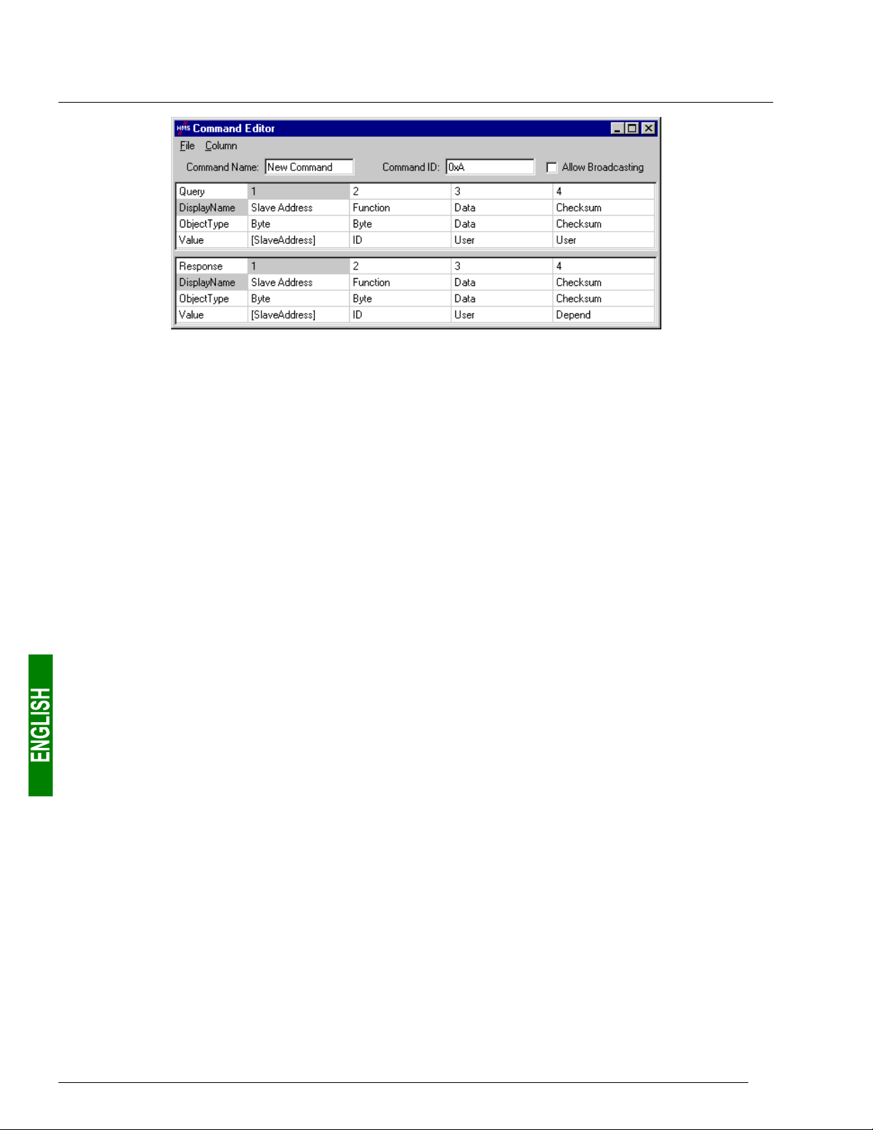
6. Configuring the Gateway
Please see chapter 2.12 Command editor in the AbcConf user manual, entitled AnyBus Communicator – User
Manual, for further information about creating standard Modbus commands. This manual can be found on the
CD LU9CD1 : “
6.11.3.2. Modbus Commands which Can Be Completely Changed by the User
In AbcConf, these commands are known as “Transactions”. Unlike in the previous case, the whole structure of
the query and response frames associated with these commands correspond to an association of input or output
data in the gateway’s memory (“Data” fields), constants in Byte, Word or DWord format and a final “Checksum”
field.
ABC_User_Manual.pdf”.
All of the data contained in the query and response “Data” fields of a “Transactions” command are managed by
the DeviceNet master, including the “Slave address” and “Function” fields if these are placed in a “Data” field.
For instance, this allows you to manage all of the Modbus frame fields from the DeviceNet master if all of the
query and response fields of a “Transactions” element (excluding “Checksum”) are “Data” type fields.
N.B. You must not place more than one “Data” field in any Modbus frame. This guarantees that all of the data
involved will be processed by the gateway at the same time.
Constants in Byte, Word or DWord format allow you to relieve the DeviceNet master by placing the values of
these constants in Modbus query frames (constants in “Query” elements) or by comparing them to the values
located in the Modbus responses (constants in “Response” elements). These comparisons are used to accept
(identical values) or reject (different values) the Modbus responses in the same way as for standard Modbus
commands. The DeviceNet master does not have access to these constants. They are mainly used to replace
fields such as “Slave address”, “Function”, “Starting Address,” etc.
Please see the section on “Actions on query/response” in chapter
objects
about how to handle “Transaction” commands. This manual can be found on the CD LU9CD1 :
“
in the AbcConf user manual, entitled AnyBus Communicator – User Manual, for further information
ABC_User_Manual.pdf”.
2.6.4 Transaction and in chapter 2.6.6 Frame
74

6. Configuring the Gateway
The LUFP9 gateway’s default configuration includes two “Transaction” commands. These are aperiodic
commands used for reading and writing the value of a Modbus slave parameter (necessarily a TeSys U motor
starter with the default configuration). They are configured solely for the “TeSys U n°1” node, as the address of
the slave is controlled by the DeviceNet master via the first byte of the “Data” field, which corresponds to the
“Slave Address” field in standard Modbus commands. This allows the DeviceNet master to send this command
to all of the Modbus slaves, slave by slave, through the first byte of the “Data” field. The remaining fields of the
frames used by these two commands are also placed in the same “Data” field. So the DeviceNet master has
access to all of the content of the frames in these two commands, excluding the checksum.
6.12. Configuring the General Characteristics of the Gateway
This operation relates to the gateway’s general characteristics (“Fieldbus”
to “Sub-Network” elements), whereas the previous chapters described the
configuration of the Modbus slaves (elements located under the “SubNetwork” element).
The “Fieldbus” element describes the upstream network, that is to say the
DeviceNet network in the case of the LUFP9 gateway.
The “ABC” and “Sub-Network” elements describe the downstream
network, that is to say the Modbus RTU network in the case of the LUFP9
gateway, and allow you to identify the software version in the gateway.
The configuration of these three elements, plus the commands they give
access to, are described in the next three chapters.
6.12.1. “Fieldbus” element
Below this element there is a list of the mailboxes configured by default. These elements are not described here,
as they are only designed for the internal management of the gateway. These mailboxes can neither be changed
nor deleted. Both their number and their nature depend on the type of upstream network.
When the “Fieldbus” element is selected, you can select the
type of upstream network. With the LUFP9 gateway, you
must select the “DeviceNet” network.
When the “DeviceNet” network is selected, you have access
to an additional field, known as “IO Sizes”.
“Automatic,” must not be changed!
If your PC is connected to the gateway using the PowerSuite cable and you are using AbcConf in “on-line” mode
when AbcConf starts up, the type of upstream network will be automatically detected.
Its value,
75

6. Configuring the Gateway
The only command accessible from the “Fieldbus”
menu is “About Fieldbus…”.
In “on-line” mode (see chapter 6.12.2 “ABC” Element,
page 76), the window shown opposite will be
displayed. In “off-line” mode the word “Unknown” will
replace “DeviceNet” to show that the type of upstream
network cannot be identified.
6.12.2. “ABC” Element
The two commands accessible from the “ABC” menu are “About ABC…” and
“Disconnect” (or “Connect” if you are in “off-line” mode).
- Running “About ABC…”
allows AbcConf to upload and
display information showing
the software version on the
PC and the software version
in the gateway.
An example is shown
opposite.
When you run “About ABC…” in “off-line” mode, the last three fields are replaced by “Unknown” to show that the
gateway software version cannot be identified.
N.B. Only the software version in the gateway’s Modbus card is displayed. This software is common to several
types of gateway marketed by
accessible using the appropriate DeviceNet object (see chapter 10.4 Identity Object (class 16#01), page 95).
- The “Disconnect” command allows you to go from “on-line” to “off-line” mode. It is only available in “on-line”
mode. It is replaced by “Connect” once you are in “off-line” mode.
Apart from these two exclusive commands, the transition to “on-line” mode is requested by AbcConf when
certain events do occur (AbcConf is launched, use of “Upload” and “Download” commands, etc.).
Schneider Electric. The gateway’s DeviceNet card software version is only
AbcConf’s connection mode is displayed to the right of its status bar:
“On-line” mode (the LED on the left is green)
“Off-line” mode (the LED on the right is red)
76

6. Configuring the Gateway
Apart from the “Control/Status Byte” and “Module Reset” options, the configuration of the LUFP9 gateway’s
“ABC” element should not be changed. Out of the four options shown below, the last two should therefore retain
the values shown: “Serial” and “Master Mode”.
These four options allow you to configure certain of the gateway’s system aspects:
- Control/Status Byte: The three possibilities available for this option are described in chapter 5 Gateway
Initialization and Diagnostics, page 33.
- Module Reset: By default, this option prevents the gateway from reinitializing itself when there is an internal
operation problem. Changing this option is mainly intended for “laboratory” type use.
- Physical Interface: The only possibility offered by this option shows that the physical interface of the network
downstream of the gateway is a serial link.
- Protocol: This option should not be changed, because it indicates the type of protocol used on the downstream
network of the gateway. With the LUFP9 gateway, “Master Mode” must be selected. The other possibilities available
are reserved for other products from the same family as this gateway.
6.12.3. “Sub-Network” Element
The five commands accessible from the “Sub-Network” menu are:
- “Monitor”: Allows you to view the correspondence between the data
from Modbus commands and the content of the gateway’s memory.
Examples of how to use this command are shown in chapters 6.8.3
(page 50), 6.8.4 (page 53) and 6.9 (page 58).
- “Add Node”: Allows you to add a new node on the downstream Modbus
network. Each node corresponds to a different Modbus slave. This
command is not available if there are already 8 Modbus slaves, which is
the case with the gateway’s default configuration.
- “Add Broadcaster”: Allows you to add a broadcaster node (see chapter 6.13 Adding a Broadcaster Node, page 79).
- “Load Node”: Allows you to add a pre-configured node on the downstream Modbus network. The configuration
for this node is contained in an XML file (see the section on “Importing/Exporting a Modbus slave configuration”
in chapter 6.7 Adding a Modbus Slave, page 46). This command is not available if there are already 8 Modbus
slaves, which is the case with the gateway’s default configuration.
77

6. Configuring the Gateway
- “Sub-Network Status…”: In “on-line” mode (see
chapter 6.12.2 “ABC” Element, page 76), this command
displays a window summarizing the values of the gateway’s
error counters. These counters are also used by the
gateway to update the value of its status word (see
chapter 5.1.2 Gateway Status Word, page 35). The
“Update” button allows you to refresh the values of these
counters.
When you run this command in “off-line” mode, all of the
values displayed are replaced by the word “Unknown” to
show that they cannot be read on the gateway. The
“Update” button then becomes inaccessible.
When the “Sub-Network” element is selected, you have access to all of the options allowing you to configure the
gateway’s communication protocol format on the Modbus network. The various settings you can make are
described below. All of the Modbus slaves present must support this configuration and be configured
appropriately.
- Bitrate (bits/s): The gateway
supports a limited number of
communication speeds.
Choose the speed that suits
your Modbus network.
- Data bits: 8 bits (required).
- Message delimiter (10ms):
Period of silence added to
the normal period of silence
between the end of one
message and the start of the
next message. The normal
period of silence
corresponds to the time
taken to transmit
3.5 characters.
- Parity: Choose the parity
according to the format
chosen for communications
on your Modbus network.
- Physical standard: RS485
(required).
- Start bits: 1 bit (required).
- Stop bits: 1 or 2 bits.
78

6. Configuring the Gateway
6.13. Adding a Broadcaster Node
A broadcaster node does not correspond to any Modbus slave in particular, as it applies to all Modbus slaves.
All the commands which will be configured for this node will be transmitted with the “Slave Address” field set to
16#00. This means that all of the slaves will run the command, but that none of them will respond to it.
To add a broadcaster node, select “Sub-Network”, then choose “Add
Broadcaster” from the “S
this way does not count in the limit on the number of configurable nodes. A
simple example is shown opposite:
The addition and configuration of a Modbus command in the list of broadcaster
node commands is done in the same way as for other nodes, but with the
following differences:
- The list of standard Modbus commands which can be used in broadcast is
considerably smaller. Only functions 16#06 and 16#10 can be used (see list
in chapter 6.11.2, page 63).
- The command is made up of a query, but does not include any response. The query bears the name of the
command itself, instead of the name “Query”. Also, each broadcast command only consumes one of the
50 queries and responses allowed by the gateway, as there is no possible response for such a command.
- The value of the query’s “Minimum time between broadcasts (10ms)” field must be changed if the default
value (1 second) is not suitable.
ub-Network” menu. The broadcaster node created in
- The value of the query frame’s “Slave Address” field is set to 16#00.
Please see chapter 6.11.2.2 Configuring the Query, page 66, for further details on how to configure a Modbus
query.
79

7. Appendix A: Technical Characteristics
7.1. Environment
Dimensions (excluding
connectors)
External appearance
Torque PSU connector: between 5 and 7 lbs.-in.
Power supply
Maximum relative humidity 95% without condensation or seepage, according to IEC 68-2-30
Ambient air temperature
around the device, in a dry
environment
UL
EC
Electromagnetic compatibility
(EMC): Transmission
Electromagnetic compatibility
(EMC): Immunity
Height: 120 mm Width: 27 mm Depth: 75 mm
Plastic case with device for fixing to a DIN rail.
24V insulated ±10%
Maximum consumption: Around 95 mA
Maximum internal consumption for all of the gateway’s electronic cards,
relating to the internal 5V PSU: 450 mA
According to IEC 68-2-1 Ab, IEC 68-2-2 Bb and IEC 68-2-14 Nb:
• Storage: –25°C (±3) to +85°C (±2)
• Operation: –05°C (±3) to +70°C (±2)
E 214107 certificate
“open type” category
The product should be installed in an electrical cabinet or in an equivalent location.
Certified as complying with European standards, unless otherwise stated.
Complies with the EN 50 081-2:1993 (industrial environment) standard
Tested according to class A radiation under the EN 55011:1990 standard
Complies with the EN 50 082-2:1995 and EN 61 000-6-2:1999 (industrial
environment) standard
Tested according to the ENV 50 204:1995, EN 61000-4-2:1995, EN 61000-43:1996, EN 61000-4-4:1995, EN 61000-4-5:1995 and EN 61000-4-6:1996
standards.
7.2. Communication Characteristics
“Upstream” network DeviceNet
“Downstream” network Modbus RTU
DeviceNet characteristics • Network topology: Multipoint linear topology (bus) with suitable line terminations
(impedance of 121 Ω ±1% ¼W).
• Physical media: Four types of specific DeviceNet cables, with built-in 24V
PSU:
c Thick double twisted pair cylindrical cable e Flat cable
d Thin double twisted pair cylindrical cable f “KwikLink” cable
• Communication speed: 125, 250, or 500 kbits/s
• Total maximum length of the network: 500 m at 125 kbits/s
250 m at 250 kbits/s
100 m at 500 kbits/s
• Maximum number of subscribers: 64
• Transactions: Up to 8 bytes of data per frame.
• Possibility of connecting or disconnecting a subscriber without affecting
communications between other subscribers.
80

7. Appendix A: Technical Characteristics
Specific DeviceNet
features of the LUFP9
gateway
Modbus RTU
characteristics
Specific Modbus RTU
features of the LUFP9
gateway
Structure of the
LUFP9 gateway’s memory:
Inputs
• The LUFP9 gateway is a “group two only server” DeviceNet subscriber (cf.
DeviceNet Specifications).
• Fragmentation support for transactions requiring more than 8 bytes of data.
• Connections supported: 1 “Explicit Connection”
1 “Polled Command/Response” connection
1 “Bit Strobed Command/Response” connection
1 “Change-of-State / Cyclic” connection
• Communication speed configured using 2 selector switches.
• Gateway’s DeviceNet address (Mac ID) configured using 6 selector switches
(address between 0 and 63).
• Configuration facilitated by the use of a specific EDS file.
• Physical media: RS485 serial link
• Network topology: Multipoint linear topology with adapted line terminations
(impedance of 120 Ω in parallel with a capacity of 1 nF)
• Communication speed: 1,200 to 57,600 kbits/s
• Data bits: 8
• Subscriber addresses: 1 to 247. Address 0 reserved for
broadcasting. Addresses 65, 126 and 127 reserved if drives and/or starters from
Schneider Electric are used on the same Modbus network.
• Period of silence: Equivalent to the transmission of 3.5 characters.
• Maximum number of subscribers (excluding gateway): 8 Modbus slaves.
• Maximum number of commands configured: Up to 50 Modbus queries and
responses configured for the same gateway using AbcConf.
• Communication speed: 1,200, 2,400, 4,800, 9,600, or 19,200 bits/s, configured
using AbcConf.
• Period of silence: Possibility of increasing the gateway’s period of silence, in
10 ms steps, using AbcConf.
• Parity: None, even or uneven, configured using AbcConf.
• Start bits: 1 bit, configuration using AbcConf.
• Stop bits: 1 or 2 bits, configuration using AbcConf.
• 2 bytes for the diagnostics of errors on the downstream network by the gateway
(see chapter 5 Gateway Initialization and Diagnostics, page 33).
• 510 bytes accessible by the DeviceNet master in the form of input data (see
chapter 8.2.1 Input Data Memory Area, page 84, for the default use of this
input data).
Addresses
16#0000
16#0001
16#0002
:
16#01FF 1 input data area
(unless “Control/Status Byte” = “Disabled”)
Inputs accessible through the DeviceNet master
Input data area
Gateway status word
510 bytes
81

7. Appendix A: Technical Characteristics
Structure of the
LUFP9 gateway’s memory:
Outputs
LUFP9 gateway’s memory:
General data
• 2 bytes for the activation or inhibition of the downstream network by the gateway
(see chapter 5 Gateway Initialization and Diagnostics, page 33).
• 510 bytes accessible by the DeviceNet master in the form of output data (see
chapter 8.2.2 Output Data Memory Area, page 85, for the default use of this
output data).
• 1,024 bytes inaccessible through the DeviceNet master.Structure of the
Addresses
16#0200
16#0201
16#0202
:
16#03FF 1 output data area
Addresses
16#0400
16#051F
16#0520
16#063F
16#0640
. . . . . . .
16#07BF
16#07C0
. . . . . . .
. . . . . . .
16#07FD
16#07FE
16#07FF
Outputs accessible through the DeviceNet master
DeviceNet master command word
(unless “Control/Status Byte” = “Disabled”)
Input area reserved for the Mailboxes
Output area reserved for the Mailboxes
Internal area reserved for the management
of the upstream network (384 bytes)
(input area / output area / bi-directional area)
Internal area reserved for the control registers
(62 bytes / MSB first for 16-bit data)
(data accessible via instance 16#01
of class 16#AA: “Diagnostic Object”)
Gateway status / DeviceNet master control
Output data area
510 bytes
General data area
(288 bytes)
(288 bytes)
(2 bytes)
Data transfer order
(swapping)
You can use the general data area for Modbus input data (from Modbus
responses) if you do not want the DeviceNet master to have access to them. In
this case,
the same addresses in this area, the corresponding memory locations will be
displayed in red in the “General Area” section of the “Sub-network Monitor”
window (see page 51 for an example). However, this will have no consequences
on the gateway during run-time.
• DeviceNet network: LSB first and MSB last.
• Modbus RTU network: MSB first and LSB last.
• LUFP9 gateway: MSB stored in the lowest memory address.
→ In most cases, the option which should be chosen for Modbus data stored in
the gateway’s memory is “Swap 2 bytes”. This option relates to all “Data” fields
for Modbus queries and responses frames.
always use 16{#4000 as the starting address. If you use multiple times
82
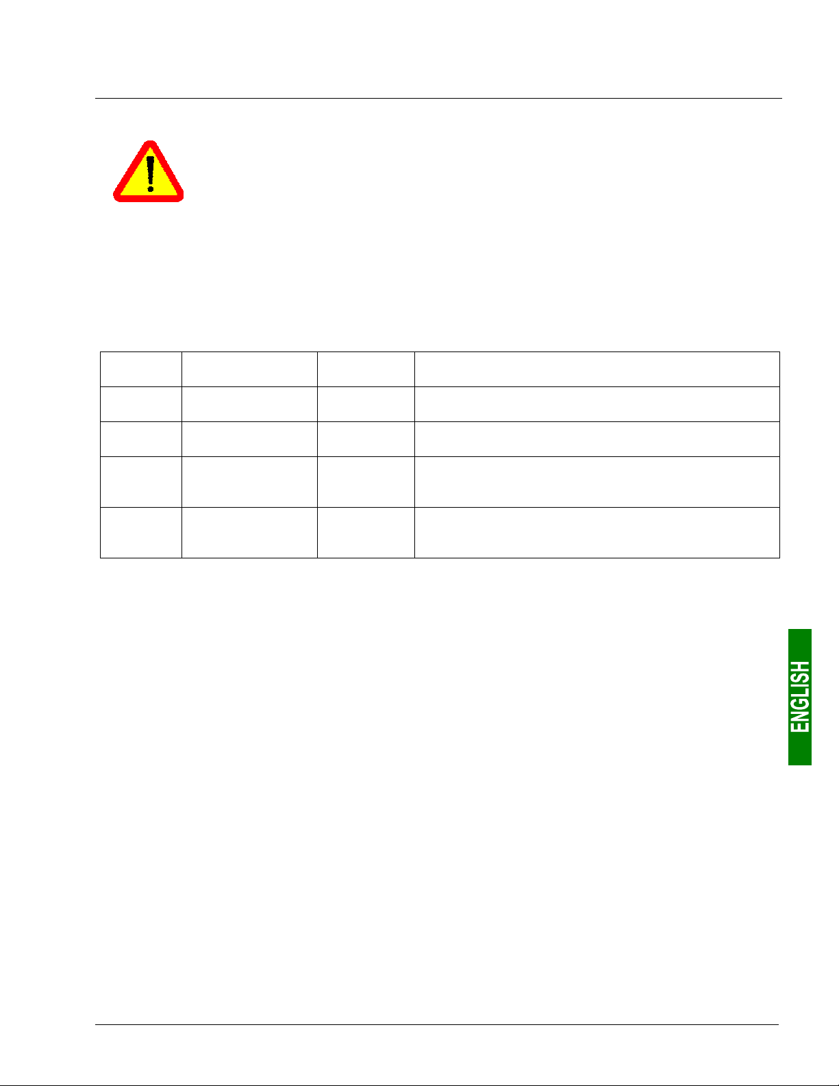
8. Appendix B: Default Configuration
The configuration described below corresponds to the LUFP9 gateway’s default configuration.
This chapter mainly gives the user information about the performances obtained on the
downstream Modbus network. It allows the user to decide whether, for example, he should
change the period for cyclical exchanges with one or more of the TeSys U motor starters (see
chapter 6 Configuring the Gateway, page 40).
8.1. Configuring Modbus exchanges
The LUFP9 gateway carries out four types of exchanges with each of the 8 TeSys U motor starters. The first two
exchanges are cyclical and allow you to control and monitor the motor starter. The last two exchanges are
aperiodic (only when there is a change in the values of the data to be transmitted to the motor starter) and allow
you to read and change the value of any motor starter parameter.
Function Modbus function
16#03
16#10
(16#03)
(16#06)
(1) Number of bytes in the Query + number of bytes in the Response, plus a period of silence of 3.5 characters
for each of these two frames (see description of the “Message delimiter (10ms)” parameter in
chapter 6.12.3 “Sub-Network” Element, page 77). Each byte will be transmitted in the form of a group of
10 bits (8 data bits, 1 start bit and 1 stop bit). These values allow you to calculate the approximate amount
of traffic on the downstream Modbus network as follows:
Volume of periodic traffic (300 ms period).....................
For 1 TeSys U motor starter ............................................................... 1 × 480 × (1,000 ÷ 300) = 01,600 bits/s
For 8 TeSys U motor starters ........................................................... 8 × 480 × (1,000 ÷ 300) = 012,800 bits/s
As a result, on a network operating at 9,600 bits/s, you will need to considerably increase the cycle time for
all or part of the periodic Modbus commands. On the other hand, at a speed of 19,200 bits/s (default
speed), the available bandwidth is sufficient to allow proper communications, even in occasional degraded
mode (frames re-transmission), and to allow the use of aperiodic setup exchanges.
Read Holding
Registers
Preset Multiple
Registers
(Read Holding
Register)
(Preset Single
Register)
Number of
bytes (1)
11,5 + 10,5
14,5 + 11,5
011,5 + 10,5
11,5 + 11,5
Exchange between the LUFP9 gateway
and the TeSys U motor starter
Periodic reading (300 ms period) of the TeSys U motor
starter’s status register (address 455 = 16#01C7) only
Periodic writing (300 ms period) of the TeSys U motor
starter’s status register (address 704 = 16#02C0) only
Aperiodic reading of the value of a single parameter, for a
single TeSys U motor starter at a time (function and
address supplied by the user)
Aperiodic writing of the value of a single parameter, for a
single TeSys U motor starter at a time (function and
address and value supplied by the user)
[ (11.5 + 10.5) + (14.5 + 11.5) ] × (8 + 1 + 1) = 480 bits
83

8. Appendix B: Default Configuration
8.2. Content of the Gateway’s DPRAM Memory
The LUFP9 gateway’s DPRAM memory contains all of the data exchanged between the gateway and the
8 TeSys U motor starters, as well as two special registers only exchanged between the gateway and the
DeviceNet master (words used for managing the downstream Modbus network).
The flow of data exchanged between the TeSys U motor starters, the gateway and the DeviceNet master is
shown below, in order to highlight the role of the gateway’s memory in these exchanges:
TeSys U motor starters
Outputs
c
d
e
j
Modbus
Inputs
8.2.1. Input Data Memory Area
The gateway has 512 input bytes. Only the first 32 bytes are used. All of these 32 bytes make up the
gateway’s input area, referenced as “Input 1” in the RsNetWorx configurator.
Service Address Size Description
LUFP9 Gateway
INPUT data
memory zone
OUTPUT data
memory zone
DeviceNet (SLC500) Master
Outputs
DeviceNet
Inputs
Managing the downstream
Modbus network
Periodic communications
—
Monitoring of
TeSys U motor starters
——
Aperiodic communications
—
Reading the value of a
motor starter parameter
RESPONSE)
(
Aperiodic communications
—
Writing the value of a
motor starter parameter
RESPONSE)
(
16#0000
16#0002
16#0004
16#0006
16#0008
16#000A
16#000C
16#000E
16#0010
16#0012
16#0013
16#0014
16#0015
16#0016
16#0018
16#0019
16#001A
16#001C
1 word Gateway status word
1 word Value of the motor starter c status register
1 word Value of the motor starter d status register
1 word Value of the motor starter e status register
1 word Value of the motor starter f status register
1 word Value of the motor starter g status register
1 word Value of the motor starter h status register
1 word Value of the motor starter i status register
1 word Value of the motor starter j status register
1 byte Memory location free
1 byte Slave no. (16#01 to 16#08)
1 byte Function number (16#03)
1 byte Number of bytes read (16#02)
1 word Value of the parameter read (16#xxxx)
1 byte Slave no. (16#01 to 16#08)
1 byte Function number (16#06)
1 word Address of the parameter written (16#xxxx)
1 word Value of the parameter written (16#xxxx)
Aperiodic communications
(“Trigger bytes” for the responses)
——
84
16#001E
16#001F
16#0020
…
16#01FF
1 byte Read parameter response counter
1 byte
1 byte
…
1 byte
Write parameter response counter
Free input area
(480 bytes)

8. Appendix B: Default Configuration
8.2.2. Output Data Memory Area
The gateway has 512 output bytes. Only the first 32 bytes are used. All of these 32 bytes make up the
gateway’s output area, referenced as “Output 1” in the RsNetWorx configurator.
Service Address Size Description
Managing the downstream
Modbus network
Periodic communications
—
Controlling
TeSys U motor starters
Aperiodic communications
—
Reading the value of a
motor starter parameter (Q
Aperiodic communications
—
Writing the value of a
motor starter parameter (Q
UERY)
UERY)
16#0200
16#0202
16#0204
16#0206
16#0208
16#020A
16#020C
16#020E
16#0210
16#0212
16#0213
16#0214
16#0216
16#0218
16#0219
16#021A
16#021C
1 word DeviceNet master command word
1 word Value of the motor starter c command register
1 word Value of the motor starter d command register
1 word Value of the motor starter e command register
1 word Value of the motor starter f command register
1 word Value of the motor starter g command register
1 word Value of the motor starter h command register
1 word Value of the motor starter i command register
1 word Value of the motor starter j command register
1 byte Slave no. (16#01 to 16#08)
1 byte Function number (16#03)
1 word Address of the parameter to be read (16#xxxx)
1 word Number of parameters to be read (16#0001)
1 byte Slave no. (16#01 to 16#08)
1 byte Function number (16#06)
1 word Address of the parameter to be written
(16#xxxx)
1 word Value of the parameter to be written (16#xxxx)
Aperiodic communications
(“Trigger bytes” for the queries)
——
8.2.3. Total Number of Modbus Queries and Responses
The total number of Modbus queries and responses is equal to 36
responses for each of the 8 TeSys U motor starters, plus 2 aperiodic queries and 2 aperiodic responses for all of
these motor starters). Since the total number of the Modbus queries and responses one can configure for a
single gateway is limited to 50, there is only 14 spare Modbus queries and responses (that is to say the
equivalent of 7 Modbus commands).
So this reserve does not allow the addition of any single Modbus command for each of the TeSys U motor
starters, as this would require the use of 16 Modbus queries and responses (1 query and 1 response for each of
the 8 motor starters).
16#021E
16#021F
16#0220
…
16#03FF
1 byte
1 byte
1 byte
…
1 byte
Read parameter query counter
Write parameter query counter
Free output area
(480 bytes)
(2 periodic queries and 2 periodic
85

9. Appendix C: Practical Example (RSLogix 500)
A practical example can be found on the CD LU9CD1. It is made up of two files. The first of these,
SLC_Guide_LUFP9.dnt”, shows the configuration of the DeviceNet scanner in RsNetWorx, described in the
“
previous chapters. The second, “
example itself.
As the configuration of the RsNetWorx file corresponds exactly to that shown in the previous chapters, we will
not be repeating its content here. On the other hand, the RSLogix 500 file is described below, based on the
structure of the sub-programs used.
9.1. Main Program: “LAD 2 - MAIN_LUFP9”
The role of the main program is to activate the DeviceNet and Modbus communications, and to call the other
sub-programs, described in later chapters. The processes carried out in the main program are described below,
in the order in which they are run:
• Validation of the scanner’s DeviceNet exchanges by activation of bit O:1.0/0.
• Activation of the gateway’s Modbus communications using bits 13 (FB_DU) and 14 (FB_HS_SEND) of the
DeviceNet master’s command word (see chapter 5 Gateway Initialization and Diagnostics, page 33). These
two bits correspond to DeviceNet scanner bits O:1.1/5 and O:1.1/6.
provided that the “Control/Status Byte” option is set to “Enabled”. With the LUFP9 gateway’s default
configuration (“Control/Status Byte” = “Enabled but no startup lock”), this process is irrelevant but may still
be kept.
and O:1.1 are no longer reserved for “managing the downstream Modbus network”. Please see chapter 5
Gateway Initialization and Diagnostics, page 33, for further information on this subject.
• Automatic acknowledgement of the gateway diagnostics by the DeviceNet master. All you have to do is
copy the value of bit 15 (ABC_HS_SEND) of the gateway’s status word to bit 15 (FB_HS_CONFIRM) of the
DeviceNet master’s command word (see chapter 5 Gateway Initialization and Diagnostics, page 33). This
automatic acknowledgement is mainly designed not to halt the mechanism for feeding diagnostics back
from the gateway to the DeviceNet master.
• Controlling/monitoring the “TeSys U n°1” motor starter by using sub-program U:3, that is to say the “LAD 3 -
CMD_SURV” sub-program. This sub-program uses local variables as parameters. The word N7:0 is used to
index both the output register and the input register used to control and monitor the “TeSys U n°1” motor
starter. So before calling the sub-program, the value of this word is set to 2 in order to access the words
O:1.2 and I:1.2. N7:0 is also used to index one of the bits of each of the registers N7:32, 33, 34 and 35
(registers handled by the user).
• Controlling/monitoring motor starter “TeSys U n°2”: Ditto, but setting the value of N7:0 to 3 (O:1.3 and I:1.3).
• Controlling/monitoring motor starter “TeSys U n°3”: Ditto, but setting the value of N7:0 to 4 (O:1.4 and I:1.4).
• Controlling/monitoring motor starter “TeSys U n°4”: Ditto, but setting the value of N7:0 to 5 (O:1.5 and I:1.5).
• Controlling/monitoring motor starter “TeSys U n°5”: Ditto, but setting the value of N7:0 to 6 (O:1.6 and I:1.6).
• Controlling/monitoring motor starter “TeSys U n°6”: Ditto, but setting the value of N7:0 to 7 (O:1.7 and I:1.7).
• Controlling/monitoring motor starter “TeSys U n°7”: Ditto, but setting the value of N7:0 to 8 (O:1.8 and I:1.8).
• Controlling/monitoring motor starter “TeSys U n°8”: Ditto, but setting the value of N7:0 to 9 (O:1.9 and I:1.9).
• Reading the value of a single parameter out of all of the TeSys U motor starters, by using the U:4 sub-
program, that is to say the “LAD 4 - LECT_PAR” sub-program.
• Writing the value of a parameter in a single TeSys U motor starter at a time, by using the U:5 sub-program,
that is to say the “LAD 5 - LECT_PAR” sub-program.
• Updating output 0:1.16 using the two counters N7:36 and N7:37. This output corresponds to the two
“Trigger bytes” that trigger the emission of both the parameter reading request (LSB) and the parameter
writing request (MSB). These two counters are independantly updated in the following sub-programs: “LAD
4 – RD_PAR”, for N7:36, and “LAD 5 – WR_PAR”, for N7:37.
Finally, this example should not be used when this option is set to “Disabled”, because words I:1.1
SLC_Guide_LUFP9_EN.rss”, is an RSLogix 500 file and so this is the
N.B. This process is only relevant
N.B. You can read a parameter on all the motor starters and write a parameter on one of them at the same time
as these services use different Modbus commands.
86

9. Appendix C: Practical Example (RSLogix 500)
The various data used by the main program are shown in the following table:
Address Symbol Description
I:1.1/07 → I:1/23 ABC_HS_SEND Flip flop indicating that there is a new gateway diagnostic
O:1.0/00 → O:1/00 SCAN_VALIDAT ION Enable DeviceNet communications: this bit must be set to 1 to validate the exchanges
O:1.1/05 → O:1/21 FB_DU Activation of Modbus communications by the gateway
O:1.1/06 → O:1/22 FB_HS_SEND Flip flop telling the gateway that there is a new command
O:1.1/07 → O:1/23 FB_HS_CONFIRM Bit used by the DeviceNet master to acknowledge diagnostics of the gateway
N7 : 0 MO D ULE Parameter giving access (index) to the motor starter (called “module” to simplify things)
O:1.16 TRIGGER_OUT_RD_WR
N7:36 ———— Local counter related to the “trigger byte” of the read parameter request
N7:37 ———— Local counter related to the “trigger byte” of the write parameter request
9.2. Controlling/Monitoring Sub-Program for a TeSys U Motor Starter: “LAD 3 CMD_MON”
The role of this sub-program consists of exercising very simple control over one of the TeSys U motor starters,
depending on its current status and the user’s commands. The processes carried out in this sub-program are
described below, in the order in which they are run:
• Control of the motor to run forward / in reverse / to stop. Register N7:0 is used as a parameter. It contains
the number of both the input word and the output word used to control and monitor the TeSys U motor
starter. This same number is used to index one of the bits of each register for registers N7:32 to N7:35. The
input word used is located between I:1.2 and I:1.9 (motor starters nos. 1 to 8), and the output word used is
located between O:1.2 et O:1.9 (
number of the motor starter currently controlled.
"Trigger bytes" used to trigger the emission of the read parameter request
(LSB) or of the write parameter request (MSB)
ditto). So the value of N7:0 must be between 2 and 9, according to the
The user controls the motor starter’s running mode using bits 2 to 9 (motor starters nos. 1 to 8) of registers
N7:32 ( Run (1) / Stop (0) ) and N7:33 (Run Forwards (0) / Reverse (1) ).
The forward, reverse and stop commands for the TeSys U motor starter are carried out under the following
conditions:
Bit 14 of a TeSys U status word = 0 ........ The motor starter is not in local mode.
Bit 02 of a TeSys U status word = 0 ........ There is no fault on the motor starter.
Bit 00 of a TeSys U status word = 1 ........ The motor starter is in the “Ready” or “Switched on” state.
When all of these conditions are met, registers N7:32 and N7:33 (bit 2 to 9, depending on the value of N7:0) are
used to control either the motor starter running forwards / in reverse, or to stop it by means of braking. The user
updates these two registers bit by bit, according to the commands he wishes to undertake.
• The faults on the TeSys U motor starter are reset. Register N7:0 is used in the same way as above and the
input and output words are the same as for controlling the motor starter.
When there is a fault on the motor starter (bit 2 of the monitoring register equal to 1), this fault is copied to
one of the bits 2 to 9 (one bit per motor starter) in register N7:34 (Faulty device (1) / Motor starter OK (0) ),
simply to show this state together with the user command which allows you to reset motor starter faults.
This user command corresponds to one of the bits 2 to 9 of register N7:35 (fault reset (1) ) and is used to
activate bit 3 of the command register of the corresponding TeSys U motor starter (“Reset” bit), that is to
say bit O:1.[N7:0]/3.
This fault reset user command is then cancelled by the program when the TeSys U motor starter no longer
shows that there is a fault.
87

9. Appendix C: Practical Example (RSLogix 500)
The various data used by this sub-program are shown in the following table:
Address Symbol Description
I:1.[N7:0]/00—Bit 00 “Ready” of the TeSys U status register
I:1.[N7:0]/01—Bit 01 “On” of the TeSys U status register
I:1.[N7:0]/02—Bit 02 “Fault” of the TeSys U status register
I:1.[N7:0]/14 —
N7:32/[N7:0] CMD_RUN [ MODULE ]
N7:33/[N7:0] CMD_REVERSE [ MODULE ]
N7:34/[N7:0] MON_FAULTY_DEV [ MODULE ]
N7:35/[N7:0] CMD_RESET [ MODULE ]
O:1.[N7:0]/00—
O:1.[N7:0]/01—
O:1.[N7:0]/02—
O:1.[N7:0]/03—
N7:0 MODULE
Bit 14 “Reserved: Local control” of the TeSys U
motor starter status register
User command: Start (1) / Stop (0) on the motor
starter whose number is N7:0
User command: Run forwards (0) / Reverse (1) on
the motor starter whose number is N7:0
User monitoring: Fault (1) / No fault (0) on the
motor starter whose number is N7:0
User command: Fault reset (1) on the motor starter
whose number is N7:0
Bit 0 “Reserved: Run Forward” of the TeSys U
command register addressed with N7:0
Bit 1 “Reserved: Run Reverse” of the TeSys U
command register addressed with N7:0
Bit 2 “Reserved (brake)” of the TeSys U command
register addressed with N7:0
Bit 3 “Reset” of the TeSys U command register
addressed with N7:0
Parameter for accessing the motor starter (index
between 2 and 9, for TeSys U motor starters nos. 1
to 8)
The example includes a personalized data monitoring screen, known as “CDM 0 - CMD_MON”, in order to
simplify the use of this example. The content of this screen is shown below:
Address Symbol Display Address Symbol Display
O:1/00 SCAN_VALIDATION Binary I:1.4 MON_TESYS_U_3 Binary
O:1/21 FB_DU Binary O:1.4 CMD_TESYS_U_3 Binary
O:1/22 FB_HS_SEND Binary I:1.5 MON_TESYS_U_4 Binary
N7:0 MODULE Decimal O:1.5 CMD_TESYS_U_4 Binary
N7:32 CMD_RUN Binary I:1.6 MON_TESYS_U_5 Binary
N7:33 CMD_REVERSE Binary O:1.6 CMD_TESYS_U_5 Binary
N7:34 MON_FAULTY_DEV Binary I:1.7 MON_TESYS_U_6 Binary
N7:35 CMD_RESET Binary O:1.7 CMD_TESYS_U_6 Binary
I:1.2 MON_TESYS_U_1 Binary I:1.8 MON_TESYS_U_7 Binary
O:1.2 CMD_TESYS_U_1 Binary O:1.8 CMD_TESYS_U_7 Binary
I:1.3 MON_TESYS_U_2 Binary I:1.9 MON_TESYS_U_8 Binary
O:1.3 CMD_TESYS_U_2 Binary O:1.9 CMD_TESYS_U_8 Binary
88

9. Appendix C: Practical Example (RSLogix 500)
9.3. Sub-Program for Reading a Parameter in all TeSys U Motor Starters: “LAD 4 RD_PAR”
The role of this sub-program is to read the value of a single parameter on all TeSys U motor starters. As they are
read, the results are placed into an array starting at N7:4 (motor starter no. 1) and ending at N7:11 (motor starter
no. 8). Index N7:2 is used to access these various addresses. The processes carried out on this sub-program
are described below, in the order in which they are run:
• If the user changes the number (or address) of the parameter to be read (N7:1) this causes the data used by the
sub-program to be reinitialized, but only if the previous reading process is finished (B3:0/0 = 0). The comparison
between N7:1 (new address) and O:1.11 (address in the last command used) is made through a scratch variable,
N9:0, in which the LSB and the MSB of the new address are swapped. The initializations are summarised below:
B3:0/0 = 1 .................... A parameter is read on all TeSys U motor starters: In progress.
Reset (C5:0) ................ The number of motor starters polled counter is reinitialized.
Reset (T4:0)................. The timer associated with the timeout for a parameter’s read response is
reinitialized.
N7:2 = 4 ....................... Index in the array of results → No. of the 1st element in the array = N7:4.
N7:3 = 1 ....................... Address of the Modbus slave polled → Address of the first TeSys U motor starter,
that is to say 1.
N7:[4..11] = 0 ............... The contents of the array of results is reset.
B3:0/5 = 0 .................... Enables the update of the “trigger byte” that will trigger the emission of the query.
• The output data corresponding to the read query is updated (O:1.10 to O:1.12) and the N7:36 counter (“trigger
byte”) is increased by one. This update is only done once (bit B3:0/5 used for this pupose).
LUFP9 gateway’s default configuration, this output data corresponds to the personalized Modbus command
“Transactions 1” of the “TeSys U n°1” node. The query frame for this personalized command is sent when the
“trigger byte” located in bits 0-7 of O:1.16 is changed (“Update mode” = “Change of state on trigger”). As a result,
increasing the N7:36 counter, then updating O:1.16 using N7:36 (in “LAD 2 – MAIN_LUFP9”), causes this query
to be sent. On the other hand, the output data O:1.10 to O:1.12 must be valid so that the content of the Modbus
query remains coherent!
Reminder: In the
• The data from the Modbus response which corresponds to this read command is checked. The values of inputs
I:1.10 and I:1.11 are compared to those of output O:1.10 and the value 16#02xx (AND mask set to 16#FF00) in
order to determine whether the response to the command has arrived or not. If the slave number and the function
number correspond to those of the query (see above) and the number of bytes of data received is correct, bit
B3:0/1 is activated in order to tell the rest of the sub-program that the response has arrived and that it is correct.
The N9:0 scratch variable is used to compare the inputs and the outputs in the same format.
• The value of the read parameter is copied into the array of results. So the value of I:1.12 is transferred to the
location reserved for the result of the motor starter currently being polled (use of index N7:2). This transfer only
takes place if the response has arrived and its content is correct (bit B3:0/1 is active). The LSB and the MSB for
this value are then swapped in this array so as to restore the value of the read parameter. The timer for the
response timeout (T4:0) is reinitialized to allow the process of reading the same parameter on the next motor
starter.
• Management of the response timeout (TON block on variable T4:0). Until the response arrives or if its content is
incorrect (bit B3:0/1 = 0), a 3-second timer is set. When this timeout (T4:0/DN = 1) is triggered, the related timer is
reinitialized and a result set to –1 is placed in the array of results, at the location normally reserved for the motor
starter being polled.
• On receipt of the response, or after the timeout has been triggered, the internal data used by this sub-program is
updated to allow the same parameter to be read on the next motor starter, up to the last of the 8 motor starters
(addresses 1 to 8). Counter C5:0 is used to count the number of motor starters which have been polled so far.
• When the reading of the 8th motor starter is finished (counter C5:0 reaching its preset value), the reading process
is halted (bit B3:0/0 is reset). However, until the reading of the parameter for the 8th motor starter has finished,
the sub-program restarts the next PLC cycle from the beginning (moving onto the next motor starter or continuing
to wait for a response for the motor starter currently being polled).
89

9. Appendix C: Practical Example (RSLogix 500)
The various data used by this sub-program are shown in the following table:
Address Symbol Description
B3.0/0 RD_RUNNING Reading a parameter on all TeSys U motor starters: In progress
Reading a parameter on all TeSys U motor starters: Reading is correct (OK) or
B3.0/1 RD_OK_KO
B3:0/5 ———— The “trigger byte” of the query has been updated: Yes (1) / No (0)
C5:0 CPT_RD_TESYS_U
I:1.10 CR_RDPAR_XXX_SLAVE
I:1.11 CR_RDPAR_FCT_BYTES
I:1.12 CR_RDPAR_VALUE
N7:1 NUMPARAM
N7:2 RD_INDEX
N7:3 ADDRESS
N7:[N7:2] — [ RD_INDEX ]
N7:36 ———— Local counter that corresponds to the “trigger byte” of the read request.
N9:0 VAR_TEMP_1 Temporary scratch variable used to carry out intermediate evaluations.
O:1.10 RDPAR_SLAVE_FCT
O:1.11 RDPAR_ADRPAR
O:1.12 RDPAR_NBPARS
T4:0 TIMEOUT_RD_PARAM Timer for the timeout of the parameter reading command (3 seconds)
incorrect (KO) for a motor starter (if the response has arrived or when timeout
T4:0 is triggered)
Reading a parameter on the TeSys U motor starters: Counter. When the value
of this counter reaches 9, the process of reading a parameter on all of the
TeSys U motor starters is halted.
Result of reading a parameter: Slave (16#01 to 16#08) as MSB. The value of
this field is compared to that of the corresponding field in the query frame. The
LSB of this input word is not used.
Result of reading a parameter: Function (always 16#03) as LSB (the value of
this field is compared to that of the corresponding field in the query frame) +
number of bytes read (16#02) as MSB (value masked and checked).
Result of reading a parameter: Value of the parameter read (MSB and LSB
are swapped). This value is placed in array N7:[N7:2], then its MSB and its
LSB are swapped there in order to restore the correct value of the read
parameter.
User command: Number of the read parameter.
Index in the array of results for the reading of a TeSys U parameter. Value = 4
to 11 (motor starters nos. 1 to 8).
Address of the Modbus slave for which one of the parameters is currently
being read. Value = 1 to 8.
Array of results used for the reading of a TeSys U parameter (motor starters
nos. 1 to 8). Elements N7:4 to N7:11 (see N7:2). Value = –1 in case of error
(response timeout triggered).
Request for the reading of a parameter: Slave (from 16#01 to 16#08) as LSB
+ function (always 16#03) as MSB.
Request for the reading of a parameter: Address of the parameter (copied
from N7:1, but with MSB and LSB swapped).
Request for the reading of a parameter: Number of parameters to be read
(always 16#0001, but with the MSB and LSB swapped, that is to say
16#0100).
The example includes a personalized screen for monitoring the data, called “CDM 1 - RD_PAR”, in order to
simplify the use of this example. The content of this screen is shown below:
Address Symbol Display Address Symbol Display
N7:1 NUMPARAM Decimal N7:10 RDPAR7 Decimal
N7:11 RDPAR8 Decimal
B3:0/0 RD_RUNNING Binary O:1.10 RDPAR_SLAVE_FCT Hexadecimal
B3:0/1 RD_OK_KO Binary O:1.11 RDPAR_ADRPAR Decimal
N7:2 RD_INDEX Decimal O:1.12 RDPAR_NBPARS Hexadecimal
N7:3 ADDRESS Decimal I:1.10 CR_RDPAR_XXX_SLAVE Hexadecimal
N7:4 RDPAR1 Decimal I:1.11 CR_RDPAR_FCT_BYTES Hexadecimal
N7:5 RDPAR2 Decimal I:1.12 CR_RDPAR_VALUE Hexadecimal
N7:6 RDPAR3 Decimal I:1.16 TRIGGER_IN_RD_WR Hexadecimal
N7:7 RDPAR4 Decimal O:1.16 TRIGGER_OUT_RD_WR Hexadecimal
N7:8 RDPAR5 Decimal N7:36 ———— Hexadecimal
N7:9 RDPAR6 Decimal B3:0/5 ———— Binary
90

9. Appendix C: Practical Example (RSLogix 500)
9.4. Sub-Program for Writing a Parameter on a Single TeSys U Motor Starter: “LAD 5 WR_PAR”
The role of this sub-program consists of writing the value of a parameter on a single TeSys U motor starter. The
user should enter the address of the TeSys U motor starter (N7:12), the address of the parameter (N7:13) and
the value to be assigned to the parameter (N7:14). Finally, he should activate bit B3:0/2 to activate the writing
process. This bit is automatically reset by the LAD 5 sub-program. When the writing process is finished, the
result of the writing (address of the parameter and value of the parameter) is copied in an array starting at N7:16
(for motor starter no. 1) and ending at N7:31 (for motor starter no. 8), using variable N7:15 as an index. Two
successive cells of this array are used for each motor starter: The first receives the parameter’s address and the
second its value. The processes carried out by this sub-program are described below, in the order in which they
are run:
• The sub-program goes into standby mode. The rest of the sub-program is not run until the user has
activated bit B3:0/2. This allows the user to enter the values of data N7:12, 13 and 14 one after another
beforehand.
• The data the sub-program uses subsequently is initialized, but only if the writing process is finished
(B3:0/3 = 0). These initializations are summarised below:
B3:0/2 = 0............................. User command: The command for writing a parameter on a TeSys U
motor starter is reset.
B3:0/3 = 1............................. A parameter is written on a TeSys U motor starter: In progress.
Reset (T4:1) ......................... The timer related to the timeout of the parameter write response is reset.
N7:15 = (N7:12 × 2) + 14 .....Index in the array of results.
N7:[N7:15] = { 0 ; 0 } ............The content of the array of results is reset, but only for the motor starter
affected by the write query (two successive bytes).
B3:0/6 = 0............................. Enables the update of the “trigger byte” that will trigger the emission of the query.
• The output data corresponding to the write query is updated (O:1.13 to O:1.15) and the N7:37 counter
(“trigger byte”) is increased by one. This update is only done once (bit B3:0/6 used for this pupose)..
Reminder: In the LUFP9 gateway’s default configuration, this output data corresponds to the personalized
Modbus command “Transactions 2” of the “TeSys U n°1” node. The query frame for this personalized
command is sent when the “trigger byte” located in bits 8-15 of O:1.16 is changed (“Update mode” =
“Change of state on trigger”). As a result, increasing the N7:37 counter, then updating O:1.16 using N7:37
(in “LAD 2 – MAIN_LUFP9”), causes this query to be sent. On the other hand, the output data O:1.13 to
O:1.15 must be valid so that the content of the Modbus query remains coherent! The LSB and the MSB of
outputs O:1.14 and O:1.15 must be swapped. The scratch variable N9:0 is used to carry out this swap
between variables N7:13 and N7:14 and outputs O:1.14 and O:1.15.
• The data from the Modbus response which corresponds to this write command is checked. The values of
inputs I:1.13 to I:1.15 are compared to those of outputs O:1.13 to O:1.15 to determine whether the response
to the command has arrived or not. If the slave number, the function number, the address of the parameter
and its value correspond to those of the query (see above) and the number of bytes of data received is
correct, bit B3:0/4 is activated in order to tell the rest of the sub-program that the response has arrived and
that it is correct.
• The address and the value of the parameter are copied into two successive locations in the array of results
(indexing carried out using N7:15), reserved for the motor starter currently being polled and only takes place
if the response has arrived and its content is correct (bit B3:0/4 active). The LSB and the MSB for each of
these two items of data are then swapped to restore its correct value. The timer for the response timeout
(T4:1) is reinitialized to ready the program for a future write command. Bit B3:0/3 is reset to show that the
command is finished, thus avoiding having to run the rest of the sub-program.
91

9. Appendix C: Practical Example (RSLogix 500)
• Management of the response timeout (T4:1). Until the response arrives or if its content is incorrect (bit
B3:0/4 = 0), a 3-second timer is set. When this timeout (T4:1/DN = 1) is triggered, the timer is reinitialized,
the parameter’s address (O:1.14, after LSB / MSB have been swapped using scratch variable N9:0) and an
erroneous value (N9:1 = –1) are placed in the array of results, into two successive locations, reserved for
the motor starter currently being polled. Finally, the write process is halted (bit B3:0/3 is reset).
The various data used by this sub-program are shown in the following table:
Address Symbol Description
B3:0/2 WR_COMMAND
B3.0/3 WR_RUNNING Writing a parameter on a TeSys U motor starter: In progress
B3.0/4 WR_OK
B3.0/6 ———— The “trigger byte” of the query has been updated: Yes (1) / No (0)
I:1.13 CR_WRPAR_SLAVE_FCT
I:1.14 CR_WRPAR_ADRPAR
I:1.15 CR_WRPAR_VALUE
N7:12 WR_SLAVE
N7:13 WR_ADDRESS
N7:14 WR_VALUE
N7:15 WR_INDEX
N7:[N7:15] — [ WR_INDEX ]
N7:37 ————
N9:0
N9:1
O:1.13 WRPAR_SLAVE_FCT
O:1.14 WRPAR_ADRPAR
O:1.15 WRPAR_VALUE
VAR_TEMP_1
VAR_TEMP_2
User command: Writing a parameter on a TeSys U motor starter.
This bit is activated by the user and reset by the program.
Writing a parameter on a TeSys U motor starter: Writing OK (if the
response has arrived and is correct)
Result of writing the value of a parameter: Slave (16#01 to 16#08)
as LSB + function (always 16#06) as MSB. The values of these
fields are compared to those of the query
Result of writing the value of a parameter: Address of the
parameter. The value of this field is compared to that of the query
(swapping of the MSB and the LSB with each of these two fields)
Result of writing the value of a parameter: Value of the written
parameter. The value of this field is compared to that of the query
(swapping of the MSB and the LSB with each of these two fields)
User command: Modbus address of the motor starter to which the
write request should be sent.
User command: Address of the parameter
N.B. Do not attempt to change the value of register 704 (command
register), because it is already controlled by the DeviceNet master
(see sub-program “LAD 3 - CMD_MON”)!
User command: New value of the parameter
Index in the array of results for writing TeSys U parameters (motor
starters nos. 1 to 8).
Value = 16 + 2 × (motor starter no. – 1) = 16 to 30
Array of results for writing TeSys U parameters (motor starters nos.
1 to 8). Elements N7:16 to N7:31 organized by “parameter address”
/ “parameter value” pairs, each pair occupying two successive
addresses.
“Parameter value” = –1 if there is an error (response timeout
triggered).
Local counter that corresponds to the “trigger byte” of the read
request.
Temporary variables used to carry out the intermediate evaluations
(primarily LSB / MSB swappings).
Request for writing the value of a parameter: Slave (copied from
N7:12) as LSB + function (always 16#06) as MSB.
Request for writing the value of a parameter: Address of the
parameter (copied from N7:13, but with MSB and LSB swapped).
Request for writing the value of a parameter: Value of the parameter
(copied from N7:14, but with MSB and LSB swapped).
92

9. Appendix C: Practical Example (RSLogix 500)
Address Symbol Description
S:24 INDEX_SYS Index register used in indexed addressing (prefix: ‘#’)
T4:1 TIMEOUT_WR_PARAM
The example includes a personalized screen for monitoring the data, called “CDM 2 - WR_PAR”, in order to
simplify the use of this example. The content of this screen is shown below:
Address Symbol Display Address Symbol Display
N7:12 WR_SLAVE Decimal N7:25 WRPAR_5_VALUE Decimal
N7:13 WR_ADDRESS Decimal N7:26 WRPAR_6_ADDRESS Decimal
N7:14 WR_VALUE Decimal N7:27 WRPAR_6_VALUE Decimal
B3:0/2 WR_COMMAND Binary N7:28 WRPAR_7_ADDRESS Decimal
B3:0/3 WR_RUNNING Binary N7:30 WRPAR_8_ADDRESS Decimal
B3:0/4 WR_OK Binary N7:31 WRPAR_8_VALUE Decimal
N7:15 WR_INDEX Decimal O:1.13 WRPAR_SLAVE_FCT Hexadecimal
N7:16 WRPAR_1_ADDRESS Decimal O:1.14 WRPAR_ADRPAR Hexadecimal
N7:17 WRPAR_1_VALUE Decimal O:1.15 WRPAR_VALUE Hexadecimal
N7:18 WRPAR_2_ADDRESS Decimal I:1.13 CR_WRPAR_SLAVE_FCT Hexadecimal
N7:19 WRPAR_2_VALUE Decimal I:1.14 CR_WRPAR_ADRPAR Hexadecimal
N7:20 WRPAR_3_ADDRESS Decimal I:1.15 CR_WRPAR_VALUE Hexadecimal
N7:21 WRPAR_3_VALUE Decimal I:1.16 TRIGGER_IN_RD_WR Hexadecimal
N7:22 WRPAR_4_ADDRESS Decimal O:1.16 TRIGGER_OUT_RD_WR Hexadecimal
N7:23 WRPAR_4_VALUE Decimal N7:37 ———— Hexadecimal
N7:24 WRPAR_5_ADDRESS Decimal B3:0/6 ———— Binary
Timer for the timeout of the parameter writing command
(3 seconds)
N7:29 WRPAR_7_VALUE Decimal
9.5. Reserves relating to the RSLogix 500 example
This example is perfectible. So, for instance, with an incorrect response (wrong slave number, function number,
etc.), the program performs no particular processing and continues to wait for a response until it times out, even
though the gateway has not re-transmitted anything because, from its point of view, the response is correct. In
fact, as the whole content of the Modbus response is placed in a “Data” field, it will not be checked before being
copied into the gateway’s memory. Only the frame’s Checksum is checked by the gateway.
The two “trigger bytes” located in the input word I:1.16 are not used. You should use them if it is relevant for your
application to be notified each time a response related to the two personalized commands “Transactions 1” and
“Transactions 2” is received by the gateway.
Compatibility with the various options offered for the “Control/Status Byte” field in “ABC” (see chapter 5 Gateway
Initialization and Diagnostics, page 33) is only partially dealt with in this example. The improvements required
relate mainly to managing bits 14 and 15 of the DeviceNet master’s command word and the gateway’s status
word (bits 6 and 7 of the corresponding input I:1.1 and output O:1.1). Also, the use of gateway diagnostics (EC
and ED fields) still needs to be defined by the user.
93

10. Appendix D: DeviceNet Objects
10.1. Introduction to the Gateway’s DeviceNet Objects
The LUFP9 gateway’s software has been developed in accordance with the Object Modelling from the
DeviceNet protocol. This model leads to a method used for addressing the gateway’s data, known as
made up of four separate values:
c the node address (MAC ID), d the Object’s class identifier (Class ID), e the
Instance Number (Instance ID) and f the Attribute Number (Attribute ID). An address made up in this way is
known as a “
Path”. The Connection by Explicit Messaging, for example, uses paths of this sort to exchange data
from one point to another on a DeviceNet network.
Address Min. – max. Description
Node 0 – 00 063
Class 1 – 65 535
Instance 0 – 65 535
Attribute 1 – 00 255
This field allows you to address one subscriber out of the series of subscribers on a
DeviceNet network using its MAC ID.
All objects sharing the same characteristics belong to the same class, characterized by its
Class ID.
The instances represent the various objects from one class. All instances from one class
share the same behaviours (1) and the same attributes, but each of them has its own set of
values for these attributes. When a subscriber creates an instance (instantiation), he assigns
a unique Instance ID, which allows the other DeviceNet subscribers to have individual
access to it.
Each attribute represents one of the characteristics of the Instances belonging to the same
class. It is assigned some sort of value (byte, unsigned integer, character string, etc.) in
order to supply information about the subscriber’s status or to make settings on the
subscriber’s behaviours (1).
N.B. To access the attributes of an object’s base class, you need to use Instance 16#00
when entering the full path. e.g. To access the “Revision” attribute from the “Identity Object”
class for DeviceNet subscriber no. 4, you will need to use the following path:
“16#04 • 16#01 • 16#00 • 16#01”.
Attributes,
(1) The behaviours designate actions taken by a DeviceNet object in response to particular events.
10.2. List of the Gateway’s DeviceNet Objects
Class ID
Identity object 16#01 Yes 1 Message router
Message router 16#02 Yes 1 Explicit message connection
DeviceNet object 16#03 Yes 1 Message router
Assembly object 16#04 No 2 (1) I/O connections or Message router
Connection object 16#05 Yes 4 (2) I/O connections or Explicit messages
Acknowledge handler object 16#2B No 1 I/O connections or Message router
I/O data input mapping object 16#A0 No 1 Message router
I/O data output mapping object 16#A1 No 1 Message router
Diagnostic object 16#AA No 1 Message router
(1) One input area and one output area are created in the gateway’s memory.
(2) The four instantiated connections are as follows:
e Bit Strobed Command/Response and f Change-of-State / Cyclic. The last three connections are of the
“I/O Connection” type.
Required
Instances Interfaces
c Explicit Connection, d Polled Command/Response,
94

10. Appendix D: DeviceNet Objects
10.3. Graphical Representation of the Gateway’s DeviceNet Objects
LUFP9 gateway memory
16#0000 16#01FF 16#0200 16#03FF 16#0400 16#07FF
Input data (1) Output data (1) General data area
Applicative
Objets
Diagnostic
Object
Identity
Object
Objets Reserved
DeviceNet
Object
Assembly
Objects
The classes which
correspond to the
grey objects are
required
Acknowledge
Handler Object
I/O
Connections
Connection Object
I/O Data Input
Mapping Object
Explicit
Messages
I/O Data Output
Mapping Object
Message
Router
DeviceNet network
for Communications
(1) The input and output data areas can be read or written either using “I/O connections” or using “explicit
messages”.
10.4. Identity Object (class 16#01)
The “Identity” object only has a single instance (Instance ID = 16#01). This object contains general information
allowing you to identify the gateway and diagnose its status. This object is described in chapter 6-2. of volume II
of the DeviceNet specifications.
Attributes of class 16#01
ID Access Name Need Type Value Description
16#01 Get Revision Required UINT 1
Services in class 16#01
Service code Name of the service Need Description
16#0E Get_Attribute_Single Required This service allows the value of one of the attributes of the class to be
Major and minor indices for the revision of the “Identity
Object”.
read.
95

10. Appendix D: DeviceNet Objects
Attributes of instance 16#01 of class 16#01
ID Access Name Need Type Value
16#01 Get
All vendor IDs for DeviceNet products are managed by the ODVA. With the LUFP9 gateway, this ID is set to 90
(gateways from HMS Fieldbus Systems AB (Hassbjer Micro Sys) ).
16#02 Get
The list of the various types of DeviceNet products is managed by the ODVA. This attribute allows a DeviceNet
subscriber’s profile to be identified, and the minimum requirements and options commonly used by the
subscribers in this profile to be deduced. The LUFP9 gateway is a “Communication Adapter” product (see
chapter 3-7. of volume II of the DeviceNet specifications).
16#03 Get
This attribute is managed by the manufacturer of the product, thus allowing him to characterize his own products.
He uses it to identify each of his products within the same product family (“device type” attribute). This allows
products with differences in terms of their configurations and/or their options to be characterized.
16#04 Get
Major and minor indices allowing the “Identity Object” to be identified. The value of each of the two members of
this attribute may not be null. The conventional representation of the revision indices is “major.minor”, with
3 digits for the minor index, completed to the left by zeros if necessary. The major index is limited to 7 data bits.
Its 8th bit is reserved and should be set to zero.
16#05 Get
This attribute is a summary of the product’s general status. This is a 16-bit register:
Bit 0 ........... Allocated to a master Bit 8...............Minor recoverable fault.
Bit 1 ........... Reserved (value = 2#0). Bit 10.............Major recoverable fault.
Bit 2 ........... Configured product. Bit 11.............Major unrecoverable fault.
Bits 3-7....... Reserved (value = 2#00000). Bits 12-15......Reserved (value = 2#0000).
16#06 Get
The product’s serial number is combined with the “vendor ID” attribute to produce a unique identifier for each
DeviceNet product. Each manufacturer must take responsibility for guaranteeing that all the DeviceNet products
he manufactures have a unique serial number.
Sample “serial number:” 16# 23 00 DD 20.
16#07 Get
This attribute gives visual identification method and takes the form of an ASCII string. This text gives a short
description of the product, or the product family, equivalent to the “product code” attribute (16#03).
The byte preceding this ASCII string shows the total length of this string, from first to the last character. With the
LUFP9 gateway, the total number of bytes included in the “product name” attribute is set to 24. The “AnybusC DeviceNet” string has 18 characters (including spaces). The whole content of the “product name” attribute, with
the LUFP9 gateway, is therefore equal to: 16# 12 41 6E 79 62 75 73 2D 43 20 44 65 76 69 63 65 4E 65 74 00 00
00 00 00. The bytes which are not shown in bold are the content of the ASCII string (length = 16#12).
16#09 Get
The value of this attribute allows the validity of the product’s configuration to be checked. The product automatically
updates this attribute when the value of any non-volatile attribute is changed. The product’s behaviour when an
error in the integrity of the configuration is detected is specific to each type of product. In the same way, the method
used to calculate the value of this attribute depends entirely on the product: CRC, unit counter, etc.
So this attribute allows a DeviceNet master, for instance, to check that the configuration of the DeviceNet product
has not been changed.
N.B. In addition to calculating the value of this attribute, the LUFP9 gateway uses its LED
warn the user when its configuration is not valid (the LED flashes red/green).
Vendor ID
Device type
Product code
Revision
Status
(predefined master/slave connection set). Bit 9...............Minor unrecoverable fault.
Serial number
Product name
Configuration consistency value
Required UINT 90
Required UINT 12
Required UINT 60
Required USINT, USINT 3 , 1
Required WORD (16-bit register)
Required UDINT (variable)
Required SHORT_STRING “Anybus-C DeviceNet”
Optional UINT (variable)
s
DEVICE STATUS to
Services of instance 16#01 of class 16#01
Service code Name of the service Requirement Description
16#05 Reset Required This service allows to restart the gateway (power cycle).
16#0E Get_Attribute_Single Required This service allows to read the value of one of the instance attributes.
96

10. Appendix D: DeviceNet Objects
10.5. Message Router Object (class 16#02)
The “Message Router” object is the element through which all objects of the “Explicit messages” type go so that
they can be routed to the objects they are intended for. It has only one instance (Instance ID = 16#01). This
object is described in chapter 6-3. of volume II of the DeviceNet specifications.
Attributes of class 16#02
ID Access Name Need Type Value Description
16#01 Get Revision Optional UINT 1 Revision index of the “Message Router Object” class.
Services in class 16#02
Service code Name of the service Need Description
16#0E Get_Attribute_Single Required This service allows to read the value of one of the class attributes.
Attributes of instance 16#01 of class 16#02
This instance has no attributes.
10.6. DeviceNet Object (class 16#03)
The “DeviceNet” object has only one instance (Instance ID = 16#01). This object contains the status of the
general configuration of the gateway’s node on the DeviceNet network. It is described in chapter 5-5. of volume
II of the DeviceNet specifications. The LUFP9 gateway is a “Group 2 only server” type subscriber (see chapter 7-
9.of volume I of the DeviceNet specifications).
Attributes of class 16#03
ID Access Name Need Type Value Description
16#01 Get Revision Required UINT 2 Revision index of the definition of the class of the “DeviceNet
Object” currently used for the implementation of the
gateway’s DeviceNet communications functions. (1)
(1) This index must be between 1 and 65,535 and will be incremented if the definition of the class is replaced
by a more recent definition.
Services in class 16#03
Service code Name of the service Need Description
16#0E Get_Attribute_Single Optional This service allows to read the value of one of the class attributes.
Attributes of instance 16#01 of class 16#03
ID Access Name Need Type Value
16#01 Get
The value of this attribute corresponds to the gateway’s address on the DeviceNet network (MAC ID), that is to
say to the address configured using the selector switches described in chapter 2.7.2 Encoding the Gateway
Address, page 21.
16#02 Get
The value of this attribute corresponds to the baud rate of the DeviceNet network, as configured on the gateway
using the selector switches described in chapter 2.7.1 Encoding DeviceNet Speed, page 20. This speed must be
the same for all subscribers on the DeviceNet network. The few possible values for this attribute are as follows:
0 (125 kbits/s), 1 (250 kbits/s) and 2 (500 kbits/s).
MAC ID
Baud rate
Required USINT 0 to 63
Optional USINT 0 to 2
97

10. Appendix D: DeviceNet Objects
ID Access Name Need Type Value
16#05 Get
This attribute supplies general information about the DeviceNet allocation method currently being used. It is made
up of the “allocation choice”, in BYTE format and the “master’s MAC ID”, in USINT format and whose value is
between 0 and 63. If the “master’s MAC ID” is set to 255 (which is the case when the gateway is initialized), this
means that there is no allocation when using the “Predefined Master/Slave Connections Set.” Please see
chapters 3-4., 5-5.4.2., and 7. of volume I of the DeviceNet specifications for further details on this subject.
Example : 16#03, 16#00.
Services of instance 16#01 of class 16#03
Service code Name of the service Need Description
16#0E Get_Attribute_Single Optional This service allows to read the value of one of the instance attributes.
16#4B Allocate Master/Slave
16#4C Release Master/Slave
Allocation information
Connection Set
Connection Set
Required BYTE , USINT (variable)
Optional This service allows the master/slave connection to be allocated to a
DeviceNet master, at the latter’s request.
Optional This service allows the master/slave connection previously allocated
to a DeviceNet master to be cleared, at the latter’s request.
10.7. Assembly Objects (Class 16#04)
As a general rule, objects from the “Assembly” class are used to group attributes (data) belonging to different
objects within a single attribute. This allows them to be accessed using a single message. With the LUFP9
gateway, this class has only 2 instances, each one being assigned to the input area (Instance ID = 16#64) or to the
output area (Instance ID = 16#96) of the gateway. This object is described in chapter 6-5. of volume II of the
DeviceNet specifications.
The first instance (Instance ID = 16#64) is assigned to the gateway’s input data area. This input area gathers all
the memory locations receiving data from a Modbus response and therefore to be relayed to the DeviceNet
master. The second instance (Instance ID = 16#96) is assigned to the gateway’s output data area. This output
area gathers all the memory locations receiving data to be placed in a Modbus query, that is to say all the data
transmitted by the DeviceNet master.
Attributes of class 16#04
ID Access Name Need Type Value Description
16#01 Get Revision Required UINT 2 Revision index of the “Assembly Object” class.
Services in class 16#04
Service code Name of the service Need Description
16#0E Get_Attribute_Single Optional This service allows to read the value of one of the class attributes.
98

10. Appendix D: DeviceNet Objects
Attributes of instance 16#64 of class 16#04 (MODBUS INPUTS)
ID Access Name Need Type Value
16#03 Get
The data gathered within this attribute correspond to the data of the attribute 16#01 of instance 16#01 from the
“I/O Data Input Mapping Object (Class 16#A0)” described in chapter 10.10 (see page 108).
With the default configuration, the size of instance 16#64 (input data area of the gateway) is equal to 32 bytes
and the data related to the attribute 16#03 of this instance corresponds to the description given in chapter 8.2.1
Input Data Memory Area, page 84.
Attributes of instance 16#96 of class 16#04 (MODBUS OUTPUTS)
ID Access Name Requirement Type Value
16#03 Get / Set
The data gathered within this attribute correspond to the data of the attribute 16#01 of instance 16#01 from the
“I/O Data Output Mapping Object (Class 16#A1)” described in chapter 10.11 (see page 109).
With the default configuration, the size of instance 16#96 (output data area of the gateway) is equal to 32 bytes
and the data related to the attribute 16#03 of this instance corresponds to the description given in chapter 8.2.2
Output Data Memory Area, page 85.
Services of instances 16#64 and 16#96 of class 16#04
Service code Name of the service Need Description
16#0E Get_Attribute_Single Required This service allows to read the array of values that corresponds to the
16#10 Get_Attribute_Single Optional This service allows to write an array of values into the array of the
Data
Data
Required USINT […] (array of values)
Required USINT […] (array of values)
attribute 16#03 of one of the instances of the “Assembly Object.”
attribute 16#03 of one of the instances of the “Assembly Object.”
10.8. Connection Object (Class 16#05)
With the LUFP9 gateway, the “Connection” object has up to four instances (Instance ID = 16#01 to 16#04). Each
of these instances represents one of the two ends of a virtual connection established between two nodes on the
DeviceNet network, in this case the DeviceNet master node and the gateway node. Each instance of this object
belongs to one of the two following types of connection: Explicit connection, allowing
sent, or implicit connection (
I/O Connections). This object is described in chapter 5-4. of volume II of the
DeviceNet specifications.
Here is a brief description of the four instances of the LUFP9 gateway’s “Connection” object, and then details are
given in the rest of this chapter:
Instance ID Type of connection Connection name
16#01 Explicit Messaging Explicit Connection
16#02 I/O Connection Polled Command/Response Connection
16#03 I/O Connection Bit Strobed Command/Response Connection
16#04 I/O Connection Change-of-State / Cyclic (Acknowledged) Connection
Each message of an “Explicit Messaging” type connection contains the full addressing path and the values of the
attribute involved, as well as the Service Code describing the action to be taken.
Each message of an “I/O Connection” type connection contains only the I/O data. All of the information
describing the use of this data is located in the instance of the “Connection Object” associated with this
message.
The instance of an “I/O connection” type object is created only if an existing data area has been
assigned to it!
Explicit Messages to be
99

10. Appendix D: DeviceNet Objects
The “Change-of-State / Cyclic Connection” connection (Instance ID 16#04) allows the gateway to produce its
data only when their values change or when a timer called “heartbeat rate” times out. A minimum time limit is
intended to prevent the connection from monopolizing the DeviceNet network’s bandwidth, should the values of
the data it produces change too often. Going into “Cyclic” mode allows the number of exchanges made via this
connection to be reduced if the update time (sampling) for the data produced is slow. By adjusting the
connection’s cycle time to the value of this time, the produced data corresponds exactly to the data samples,
without losing or repeating any sample.
Attributes of class 16#05
ID Access Nam e Nee d Type Value Des crip tion
16#01 Ge t Revisi on Optional UI NT 1 Revis ion inde x of t he “ Conn ection O bjec t” class .
16#64 Get / Set P olled produ ction Optional USI NT 0 Index of t he i nput are a use d by the gateway for
production on its “Polled Command/Response”
connection. (1)
16#65 Get / Set Polled consumption Optional USINT 0 Index of the output are a used by the g ateway f or
consumption on its “Polled Command/Response”
connection. (1)
16#66 Get / Set Strobed production Optional USINT 0 Index of the inp ut area used b y the gate way for
production on its “Bit Strobed Command/Response”
connection. (1)
16#67 Get / Set Strobed consumption Optional USINT 0 I ndex of t he outpu t area used by the g ateway for
consumption on its “Bit Strobed Command/Response”
connection. (1)
16#68 Get / Set COS production Optional USINT 0
Index of the input area used by the gateway for
production on its “Bit Strobed Command/Response”
connection. (1)
(1) All these 5 attributes relate to the first 5 parameters referenced by the EDS file supplied with the gateway.
Write access to them (Access = Set) is reserved for DeviceNet configuration tools. You should not use the
“Set_Attribute_Single” service with these attributes. An area’s index is necessarily equal to 0 and
corresponds to the “Input1” area of the gateway, that is to say to its only one input data area.
Services in class 16#05
Service code Name of the service Need Description
16#0E Get_Attribute_Single Required This service allows to read the value of one of the class
attributes.
Attributes of instance 16#01 of class 16#05: Explicit Connection
ID Access Name Need Type Value
16#01 Get
This attribute represents the status of the “Explicit Connection” object. The LUFP9 gateway supports the
following values: 0 (non-existent), 1 (in the process of being configured), 3 (connection established), 4 (timed out)
and 5 (deferred deletion). Please see figures 5.16 and 7.4 in volume I of the DeviceNet specifications for further
information on this subject.
16#02 Get
This attribute defines the instance’s connection type: Messaging connection (0) or I/O connection (1).
State
Instance type
Required USINT 0 to 5
Required USINT 0
100
 Loading...