


TECHNICAL & SERVICE MANUAL
KGS1411 / CG1411
FILE NO.
Destination: U.S.A.
GAS HEATER AIR CONDITIONER
Indoor Model No. |
Product |
Code No. |
|
|
|
KGS 1411 |
1 852 |
062 56 |
Outdoor Model No. Product Code No.
CG 1411 |
1 714 734 00 |
Indoor Unit |
|
Outdoor Unit |
|
|
|
KGS1411 |
CG1411 |
REFERENCE NO. SM700361
W
IMPORTANT!
Please Read Before Starting
This air conditioning system meets strict safety and operating standards. As the installer or service person, it is an important part of your job to install or service the system so it operates safely and efficiently.
For safe installation and trouble-free operation, you must:
●Carefully read this instruction booklet before beginning.
●Follow each installation or repair step exactly as shown.
●Observe all local, state, and national electrical codes.
●Pay close attention to all warning and caution notices given in this manual.
This symbol refers to a hazard or
WARNING unsafe practice which can result in severe personal injury or
death.
This symbol refers to a hazard or
CAUTION
unsafe practice which can result in personal injury or product or property damage.
If Necessary, Get Help
These instructions are all you need for most installation sites and maintenance conditions. If you require help for a special problem, contact our sales/service outlet or your certified dealer for additional instructions.
In Case of Improper Installation
The manufacturer shall in no way be responsible for improper installation or maintenance service, including failure to follow the instructions in this document.
SPECIAL PRECAUTIONS
WARNING When Wiring
ELECTRICAL SHOCK CAN CAUSE SEVERE PERSONAL INJURY OR DEATH. ONLY A QUALIFIED, EXPERIENCED ELECTRICIAN SHOULD ATTEMPT TO WIRE THIS SYSTEM.
•Do not supply power to the unit until all wiring and tubing are completed or reconnected and checked.
•Highly dangerous electrical voltages are used in this system. Carefully refer to the wiring diagram and these instructions when wiring. Improper connections and inadequate grounding can cause accidental injury or death.
•Ground the unit following local electrical codes.
•Connect all wiring tightly. Loose wiring may cause overheating at connection points and a possible fire hazard.
When Transporting
Be careful when picking up and moving the indoor and outdoor units. Get a partner to help, and bend your knees when lifting to reduce strain on your back. Sharp edges or thin aluminum fins on the air conditioner can cut your fingers.
When Installing…
…In a Ceiling or Wall
Make sure the ceiling/wall is strong enough to hold the unit’s weight. It may be necessary to construct a strong wood or metal frame to provide added support.
…In a Room
Properly insulate any tubing run inside a room to prevent “sweating” that can cause dripping and water damage to walls and floors.
…In Moist or Uneven Locations
Use a raised concrete pad or concrete blocks to provide a solid, level foundation for the outdoor unit. This prevents water damage and abnormal vibration.
…In an Area with High Winds
Securely anchor the outdoor unit down with bolts and a metal frame. Provide a suitable air baffle.
…In a Snowy Area (for Heat Pump-type Systems)
Install the outdoor unit on a raised platform that is higher than drifting snow. Provide snow vents.
When Connecting Refrigerant Tubing
•Use the flare method for connecting tubing.
•Apply refrigerant lubricant to the matching surfaces of the flare and union tubes before connecting them, then tighten the nut with a torque wrench for a leak-free connection.
•Check carefully for leaks before starting the test run.
When Servicing
•Turn the power OFF at the main power box (mains) before opening the unit to check or repair electrical parts and wiring.
•Keep your fingers and clothing away from any moving parts.
•Clean up the site after you finish, remembering to check that no metal scraps or bits of wiring have been left inside the unit being serviced.
Others
CAUTION
•Ventilate any enclosed areas when installing or testing the refrigeration system. Escaped refrigerant gas, on contact with fire or heat, can produce dangerously toxic gas.
•Confirm upon completing installation that no refrigerant gas is leaking. If escaped gas comes in contact with a stove, gas water heater, electric room heater or other heat source, it can produce dangerously toxic gas.
i
Table of Contents
|
|
|
Page |
1. |
OPERATING RANGE ................................................................................................................ |
1 |
|
2. |
SPECIFICATIONS |
|
|
|
2-1. |
Unit Specifications ............................................................................................................ |
2 |
|
2-2. |
Major Component Specifications...................................................................................... |
4 |
|
2-3. |
Other Component Specifications...................................................................................... |
7 |
3. |
DIMENSIONAL DATA |
|
|
|
3-1. |
Unit ................................................................................................................................... |
9 |
|
3-2. |
Internal Components ........................................................................................................ |
11 |
|
3-3. |
Major Components ........................................................................................................... |
13 |
4. |
REFRIGERANT FLOW DIAGRAM |
|
|
|
4-1. |
Refrigerant Flow Diagram................................................................................................. |
16 |
5. |
PERFORMANCE DATA |
|
|
|
5-1. |
Performance Charts ......................................................................................................... |
17 |
|
5-2. Air Throw Distance Charts ............................................................................................... |
18 |
|
|
5-3. |
Cooling Capacity .............................................................................................................. |
19 |
|
5-4. |
Heating Capacity .............................................................................................................. |
20 |
6. |
ELECTRICAL DATA |
|
|
|
6-1. |
Electrical Characteristics .................................................................................................. |
21 |
|
6-2. |
Electric Wiring Diagrams .................................................................................................. |
22 |
7. |
INSTALLATION INSTRUCTIONS |
|
|
|
7-1. |
Installation Site Selection ................................................................................................. |
25 |
|
7-2. Recommended Wire Length and Diameter ...................................................................... |
27 |
|
|
7-3. Remote Control Unit Installation Position ......................................................................... |
28 |
|
8. |
FUNCTION |
|
|
|
8-1. |
Motion Explanation ........................................................................................................... |
29 |
|
8-2. |
Cooling ............................................................................................................................. |
31 |
|
8-3. |
Heating ............................................................................................................................. |
33 |
|
8-4. |
Fan Speed Control ........................................................................................................... |
37 |
|
8-5. |
Dry Operation (Dehumidification) ..................................................................................... |
38 |
|
8-6. |
Automatic Operation......................................................................................................... |
39 |
|
8-7. |
Freeze Prevention............................................................................................................. |
40 |
|
8-8. |
Overload Prevention (Heating) ......................................................................................... |
41 |
9. |
OPERATION FLOWCHARTS |
|
|
|
9-1. |
Cooling, Dry...................................................................................................................... |
42 |
|
9-2. |
Heating ............................................................................................................................. |
43 |
ii

10. PROCEDURE FOR DISMANTLING THE UNIT |
|
10-1. Procedure for Dismantling the Indoor Unit ....................................................................... |
44 |
10-2. Procedure for Dismantling the Outdoor Unit..................................................................... |
47 |
11. POINTS TO DIAGNOSE |
|
11-1. Indoor Unit Alarm Signal .................................................................................................. |
50 |
11-2. Manifold Pressure............................................................................................................. |
50 |
11-3. Checking Electrical Components...................................................................................... |
51 |
12. TROUBLESHOOTING |
|
12-1. Check Before and After Troubleshooting .......................................................................... |
53 |
12-2. When the Air Conditioner Does Not Work at All (Both Indoor and Outdoor Units) — |
|
Operation Lamp Does Not Light ....................................................................................... |
54 |
12-3. Operation Lamp Blinks (It Keeps Blinking after 3 Minutes Following Start of Operation). |
54 |
12-4. Outdoor Unit Fan Does Not Work..................................................................................... |
58 |
12-5. Flap Motor Does Not Work ............................................................................................... |
59 |
12-6. Heating Operation Not Possible ....................................................................................... |
59 |
12-7. Reset Method When Error Occurs During Heating Operation ......................................... |
63 |
12-8. Failure Display on Outdoor Unit and Correction Method .................................................. |
64 |
13. SPECIAL PRECAUTIONS WHEN SERVICING THE UNIT |
|
13-1. BLK/WHT Connector Attachment for Servicing................................................................ |
65 |
13-2. Refrigerant Recovery........................................................................................................ |
66 |
13-3. Service on Outdoor Unit ................................................................................................... |
66 |
13-4. Evacuation Using Vacuum Pump ..................................................................................... |
66 |
13-5. Refrigerant Charging ........................................................................................................ |
67 |
13-6. Reattaching BLK/WHT Connectors for Operation ............................................................ |
68 |
APPENDIX INSTRUCTION MANUAL |
|
iii
1. OPERATING RANGE
|
Temperature |
Indoor Air Intake Temp. |
Outdoor Air Intake Temp. |
|
|
|
|
Cooling |
Maximum |
95°F (35°C) D.B. |
115°F (46.1°C) D.B. |
|
|
71°F (21.7°C) W.B. |
|
|
|
|
|
|
Minimum |
67°F (19.4°C) D.B. |
67°F (19.4°C) D.B. |
|
|
57°F (13.9°C) W.B. |
|
|
|
|
|
Heating |
Maximum |
80°F (26.7°C) D.B. |
75°F (23.9°C) D.B. |
|
|
67°F (19.4°C) W.B. |
65°F (18.3°C) W.B. |
|
|
|
|
|
Minimum |
— D.B. |
0°F (–17.8°C) D.B. |
|
|
— W.B. |
–2°F (–19°C) W.B. |
|
|
|
|
1

2. SPECIFICATIONS
2-1. Unit Specifications
Indoor unit |
KGS1411 |
|
|
|
|
|
|
|
|
Outdoor unit |
CG1411 |
|
|
|
|
|
|
|
|
|
|
|
|
|
|
|
|
|
|
Power Source |
|
|
|
|
|
Cooling |
|
Heating |
|
|
|
|
|
|
|
|
|
|
|
|
Electric power source |
|
|
|
|
|
115V 60Hz |
||
|
|
|
|
|
|
|
|
|
|
|
Employed gas |
|
|
|
|
— |
|
Natural gas (LP) |
|
|
|
|
|
|
|
|
|
|
|
|
|
|
|
|
|
|
|
|
|
|
|
|
|
|
|
|
Cooling |
|
Heating |
|
|
|
|
|
|
|
|
|
|
Voltage Rating |
|
|
|
|
|
|
115V |
||
|
|
|
|
|
|
|
|
|
|
|
|
|
|
|
|
|
|
|
|
Performance |
|
|
|
|
|
Cooling |
|
Heating |
|
|
|
|
|
|
|
|
|
|
|
|
Capacity |
|
|
kW |
|
2.58 |
|
4.1 / 2.9 / 1.8 |
|
|
|
|
|
|
|
|
8,800 |
|
14,000 / 9,900 / 6,150 |
|
|
|
|
|
|
|
|
||
|
Air circulation (High) |
|
ft3/min (m3/min) |
|
282 (8.0) |
|
300 (8.5) |
||
|
Moisture removal (High) |
|
|
Pints/h |
|
2.2 |
|
— |
|
|
|
|
|
|
|
|
|
|
|
|
|
|
|
|
|
|
|
||
Electrical Rating |
|
|
|
|
Cooling |
|
Heating |
||
|
|
|
|
|
|
|
|
|
|
|
Available voltage range |
|
|
V |
|
|
104 – 126 |
||
|
|
|
|
|
|
|
|
||
|
Running amperes |
|
|
A |
|
8.2 |
|
5.9 |
|
|
|
|
|
|
|
|
|
|
|
|
Power input |
|
|
W |
|
900 |
|
620 |
|
|
|
|
|
|
|
|
|
|
|
|
Power factor |
|
|
% |
|
95 |
|
91 |
|
|
|
|
|
|
|
|
|
|
|
|
SEER |
|
|
|
BTU/W |
|
10.0 |
|
— |
|
|
|
|
|
|
|
|
||
|
Compressor locked rotor amperes |
|
A |
|
|
49 |
|||
|
|
|
|
|
|
|
|
|
|
|
|
|
|
|
|
|
|
|
|
Features |
|
|
|
|
|
|
|
|
|
|
Controls / Temperature control |
|
|
|
Microprocessor / I.C. thermostat |
||||
|
|
|
|
|
|
|
|||
|
Control unit |
|
|
|
|
Wireless remote control unit |
|||
|
|
|
|
|
|
|
|
||
|
Timer |
|
|
|
|
|
ON / OFF 12 hours, 1-hour OFF |
||
|
|
|
|
|
|
|
|||
|
Fan speeds |
Indoor / Outdoor |
|
|
|
3 and Auto / 1 (Hi) |
|||
|
|
|
|
|
|
||||
|
Airflow direction (Indoor) |
Horizontal |
|
|
Manual |
||||
|
|
|
|
|
Vertical |
|
|
Auto |
|
|
|
|
|
|
|
|
|
||
|
Air filter |
|
|
|
|
|
Washable |
||
|
|
|
|
|
|
|
|
||
|
Compressor |
|
|
|
|
|
Rotary (Hermetic) |
||
|
|
|
|
|
|
||||
|
Refrigerant / Amount charged at shipment |
lb. (kg) |
|
|
1.34 (0.61) |
||||
|
|
|
|
|
|
|
|
||
|
Refrigerant control |
|
|
|
|
|
Capillary tube |
||
|
|
|
|
|
|
||||
|
Operation sound |
Indoor: Hi / Me / Lo dB-A |
|
39 / 37 / 34 |
|
41 / 38 / 33 |
|||
|
|
|
Outdoor: Hi |
|
dB-A |
|
45 |
|
43 |
|
|
|
|
|
|
|
|
||
|
Refrigerant tubing connections |
|
|
|
|
Flare |
|||
|
|
|
|
|
|
||||
|
Max allowable tubing length at shipment |
ft. (m) |
|
|
25 (7.5) |
||||
|
|
|
|
|
|
|
|||
|
Refrigerant tubing |
Narrow tube |
inch (mm) |
|
|
1/4 (6.35) |
|||
|
diameter |
Wide tube |
|
inch (mm) |
|
|
3/8 (9.52) |
||
|
|
|
|
|
|
|
|
||
|
|
|
|
|
|
|
DATA SUBJECT TO CHANGE WITHOUT NOTICE. |
||
Remarks: Rating conditions are |
|
|
|
|
|
|
|
||
|
Cooling: Indoor air temperature |
80°F D.B. / 67°F W.B. |
|
|
|
||||
|
|
Outdoor air temperature |
95°F D.B. / 75°F W.B. |
|
|
|
|||
|
Heating: Indoor air temperature |
70°F D.B. |
|
|
|
||||
|
|
Outdoor air temperature |
47°F D.B. / 43°F W.B. |
|
|
|
|||
2
Indoor unit |
KGS1411 |
|
|
|
|
|
|
|
|
|
Outdoor unit |
CG1411 |
|
|
|
|
|
|
|
|
|
|
|
|
|
|
|
|
|
|||
Dimensions & Weight |
|
|
|
Indoor Unit |
|
Outdoor Unit |
||||
|
|
|
|
|
|
|
|
|||
|
Unit dimensions |
Height |
|
inch (mm) |
10-5/8 (270) |
|
23-7/32 (590) |
|||
|
|
|
Width |
|
inch (mm) |
31-11/16 (805) |
|
28-1/2 (724) |
||
|
|
|
Depth |
|
inch (mm) |
6-31/32 (177) |
|
11-15/32 (291) |
||
|
|
|
|
|
|
|
|
|||
|
Package dimensions |
Height |
|
inch (mm) |
9-13/16 (249) |
|
31-1/16 (789) |
|||
|
|
|
Width |
|
inch (mm) |
33-21/32 (855) |
|
25-1/32 (636) |
||
|
|
|
Depth |
|
inch (mm) |
13-5/16 (338) |
|
14-29/32 (379) |
||
|
|
|
|
|
|
|
|
|
||
|
Weight |
|
Net |
|
lb. (kg) |
17.6 (8.0) |
|
85.7 (39.0) |
||
|
|
|
Shipping |
|
lb. (kg) |
22.0 (10.0) |
|
90.8 (41.0) |
||
|
|
|
|
|
|
|
|
|||
|
Shipping volume |
|
|
cu.ft (m3) |
2.51 (0.071) |
|
6.72 (0.19) |
|||
|
|
|
|
|
|
|
|
|
||
Burner |
|
|
|
|
Natural gas |
|
|
LP |
||
|
Burner type |
|
|
|
|
Ribbon burner |
|
|||
|
|
|
|
|
|
|
|
|||
|
Burner configuration |
|
|
|
|
Slit type |
|
|||
|
|
|
|
|
|
|
|
|
||
|
|
|
|
|
|
|
|
|
|
|
Gas Consumption |
|
|
|
Natural gas |
|
|
LP |
|||
|
|
|
|
|
|
|
|
|||
|
Typical input |
BTU/h (kW) |
|
High |
15,500 (4.55) |
|
15,500 (0.719 lb./h) |
|||
|
|
|
|
|
Medium |
10,400 (3.05) |
|
10,400 (0.482 lb./h) |
||
|
|
|
|
|
Low |
6,150 (1.80) |
|
6,150 (0.285 lb./h) |
||
|
|
|
|
|
|
|
|
|
||
|
|
|
|
|
|
|
|
|||
Governor Setting Pressure |
|
|
|
Natural gas |
|
|
LP |
|||
|
|
|
|
|
|
|
|
|
|
|
|
|
|
|
|
|
P2 |
P1 |
|
P2 |
P1 |
|
|
|
|
|
|
|
|
|
||
|
P2, P1 |
Inches water column (kPa) |
High |
3.43 (0.853) |
7.0 (1.74) |
|
3.54 (0.883) |
11.0 (2.74) |
||
|
|
|
|
|
Medium |
1.61 (0.402) |
" |
|
1.61 (0.402) |
" |
|
|
|
|
|
Low |
0.63 (0.157) |
" |
|
0.63 (0.157) |
" |
|
|
|
|
|
|
|
|
|
|
|
Gas Nozzle |
|
|
|
|
Natural gas |
|
|
LP |
||
|
|
|
|
|
|
|
||||
|
Inner diameter |
|
ø inch (ø mm) |
0.0807 (2.05) |
|
0.0630 (1.60) |
||||
|
|
|
|
|
|
|
|
|
|
|
|
Q’ty |
|
|
|
|
|
1 |
|
|
1 |
|
|
|
|
|
|
|
|
|||
|
|
|
|
|
|
|
||||
Safety Devices |
|
|
|
Cooling |
|
Heating |
||||
|
|
|
|
|
|
|
|
|
||
|
Re-start timer (3 minute) |
|
|
|
|
● |
|
|||
|
|
|
|
|
|
|
|
|||
|
Compressor over-load limiting |
|
|
|
|
● |
|
|||
|
|
|
|
|
|
|
|
|
||
|
Circuit fuse |
|
|
|
|
|
● |
|
||
|
|
|
|
|
|
|||||
|
Current limit function (out of range between 0.8 – 17A) |
|
|
● |
|
|||||
|
Thermal fuse |
|
|
|
|
— |
|
|
● |
|
|
Auto reset temperature limiting 221°F (105°C) |
|
— |
|
|
● |
||||
|
Flame rod |
|
|
|
|
— |
|
|
● |
|
|
|
|
|
|
|
|
|
|||
|
|
|
|
|
|
DATA SUBJECT TO CHANGE WITHOUT NOTICE. |
||||
Remarks: Rating conditions are |
|
|
|
|
|
|
|
|
||
|
Cooling: Indoor air temperature |
80°F D.B. / 67°F W.B. |
|
|
|
|
||||
|
|
Outdoor air temperature |
95°F D.B. / 75°F W.B. |
|
|
|
|
|||
|
Heating: Indoor air temperature |
70°F D.B. |
|
|
|
|
|
|||
|
|
Outdoor air temperature |
47°F D.B. / 43°F W.B. |
|
|
|
|
|||
3

2-2. Major Component Specifications
2-2-1. Indoor Unit
Indoor unit KGS1411
Control PCB |
|
|
|
|
||
|
|
|
|
|
|
|
|
Part No. |
|
|
POW-KGS14A, B |
||
|
Controls |
|
|
Microprocessor |
||
|
|
|
|
|
|
|
|
Control circuit fuse |
|
|
|
115V |
|
|
|
|
|
|
|
|
|
|
|
|
|||
Remote Control Unit |
|
|
RCS-IRS2U |
|||
|
|
|
|
|
||
|
|
|
|
|
|
|
Fan & Fan Motor |
|
|
|
|
||
|
Type |
|
|
Cross-flow |
||
|
|
|
|
|
||
|
Q’ty … Dia. and length |
inch (mm) |
1 … ø 95 / L617 (ø 3-3/4 / L24-9/32) |
|||
|
|
|
|
|
|
|
|
Fan motor model … Q’ty |
|
|
KFV4-21HIP … 1P |
||
|
|
|
|
|
|
|
|
Nominal output |
|
W |
|
15 |
|
|
|
|
|
|
|
|
|
Coil resistance (ambient temp. 68°F (20°C)) |
Ω |
BLU |
– BRN: 104.9 |
||
|
|
|
|
|
BLU |
– PNK: 128.0 |
|
|
|
|
|
|
|
|
Safety devices Type |
|
|
|
X23 |
|
|
|
|
|
|
||
|
|
Operating temp. |
Open °F (°C) |
259 (126) ±4 (±2) |
||
|
|
|
Close |
|
|
— |
|
Run capacitor |
|
µF |
|
3.5 |
|
|
|
|
|
VAC |
|
180 |
|
|
|
|
|
|
|
|
|
|
|
|
|
|
Flap Motor |
|
|
|
|
||
|
|
|
|
|
|
|
|
Type |
|
|
Stepping motor |
||
|
|
|
|
|
|
|
|
Model |
|
|
MP24GA1 |
||
|
|
|
|
|
|
|
|
Rating |
|
|
|
DC12V |
|
|
|
|
|
|
||
|
Coil resistance (ambient temp. 77°F (25°C)) |
Ω |
WHT – BLU (respectively 4 wires): 380 ± 7% |
|||
|
|
|
|
|
|
|
|
|
|
|
|
|
|
Heat Exchanger Coil |
|
|
|
|
||
|
|
|
|
|
|
|
|
Coil |
|
|
Aluminum plate fin / Copper tube |
||
|
|
|
|
|
|
|
|
Rows |
|
|
|
2 |
|
|
|
|
|
|
|
|
|
Fin pitch |
inch (mm) |
|
1/16 (1.4) |
||
|
|
|
|
|
|
|
|
Face area |
|
ft2 (m2) |
1.40 (0.130) |
||
DATA SUBJECT TO CHANGE WITHOUT NOTICE.
4

2-2-2. Outdoor Unit (1)
Outdoor unit CG1411
Control PCB |
|
|
|
|
|
|
|
|
|
|
|
|
Part No. |
|
|
|
CG1411 |
|
Controls |
|
|
|
Microprocessor |
|
|
|
|
|
|
|
Control circuit fuse |
|
|
115V 5A |
|
|
|
|
|
|
|
|
|
|
|
|
|
Gas Connection |
|
|
|
|
|
|
|
|
|
|
|
|
Employed gas |
|
|
|
Natural Gas (LP) |
|
|
|
|
|
|
|
Gas connection |
|
|
|
1/2 Female |
|
|
|
|
|
|
|
|
|
|
|
|
Compressor |
|
|
|
|
|
|
|
|
|
|
|
|
Type |
|
|
|
Rotary (Hermetic) |
|
Compressor model |
|
|
C-1R71H2W |
|
|
|
|
|
|
|
|
Nominal output |
|
|
W |
700 |
|
|
|
|
|
|
|
Compressor oil … Amount |
|
cc |
SUNISO 4GSD-T … 370 |
|
|
|
|
|
||
|
Coil resistance (ambient temp. 68°F (20°C)) |
Ω |
C – R: 0.879 |
||
|
|
|
|
|
C – S: 3.609 |
|
|
|
|
|
|
|
Safety devices |
Type |
|
|
External (OLR) |
|
|
|
|
|
|
|
|
Overload relay |
|
|
MRA98962-9200 |
|
|
|
|
|
|
|
|
Operating temp. |
Open °F (°C) |
275 ± 9 (135 ± 5) |
|
|
|
|
Close °F (°C) |
156 ± 20 (69 ± 11) |
|
|
|
|
|
||
|
|
Operating amp (ambient temp. 77°F (25°C)) |
Trip in 6 to 16 sec. at 34A |
||
|
|
|
|
|
|
|
Run capacitor |
|
|
µF |
35 |
|
|
|
|
VAC |
330 |
|
|
|
|
|
|
|
PTC starter |
Part number |
|
|
912X24E400XR20-PS2A |
|
|
Resistance |
|
Ω |
47 |
|
|
Max voltage |
|
|
300 |
|
|
|
|
|
|
|
Crank case heater |
|
|
— |
|
|
|
|
|
|
|
|
|
|
|
|
|
Fan & Fan Motor |
|
|
|
|
|
|
|
|
|
|
|
|
Type |
|
|
|
Propeller |
|
|
|
|
||
|
Q’ty … Dia. and length |
inch. (mm) |
1 … 13-25/32 (ø 350) |
||
|
|
|
|
|
|
|
Fan motor model … Q’ty |
|
|
SB6-11H1P … 1 |
|
|
|
|
|
|
|
|
No. of poles … rpm (115V, High) |
|
|
6 … 600 |
|
|
|
|
|
|
|
|
Nominal output |
|
|
W |
10 |
|
|
|
|
||
|
Coil resistance (ambient temp. 77°F (25°C)) |
Ω |
BLU – BRN: 114.0 ± 7% |
||
|
|
|
|
|
BLU – WHT: 153.4 ± 7% |
|
|
|
|
|
|
|
Safety devices |
Type |
|
|
Thermostat |
|
|
|
|
|
|
|
|
Operating temp. |
Open °F (°C) |
266 ± 14 (130 ± 8) |
|
|
|
|
Close °F (°C) |
174 ± 27 (79 ± 15) Automatic reclosing |
|
|
|
|
|
|
|
|
Run capacitor |
|
|
µF |
5.0 |
|
|
|
|
VAC |
220 |
|
|
|
|
|
|
|
|
|
|
|
|
Heat Exchanger Coil |
|
|
|
|
|
|
|
|
|
|
|
|
Coil |
|
|
|
Aluminum plate fin / Copper tube |
|
|
|
|
|
|
|
Rows |
|
|
|
1 |
|
|
|
|
|
|
|
Fin pitch |
|
inch (mm) |
1/16 (1.3) |
|
|
|
|
|
|
|
|
Face area |
|
|
ft2 (m2) |
2.73 (0.254) |
|
|
|
|
|
|
External Finish |
|
|
|
Acrylic baked-on enamel finish |
|
|
|
|
|
|
|
DATA SUBJECT TO CHANGE WITHOUT NOTICE.
5

2-2-2. Outdoor Unit (2)
Outdoor unit CG1411
Burner |
|
|
|
|
||
|
|
|
|
|
|
|
|
Type |
|
|
|
Ribbon burner |
|
|
|
|
|
|
||
|
Q’ty … Material, thickness |
inch (mm) |
1 … Stainless steel, 0.0157 (0.4) |
|||
|
|
|
|
|
|
|
|
|
|
|
|
|
|
Nozzle |
|
|
|
|
||
|
|
|
|
|
|
|
|
Q’ty … Material |
|
|
|
1 … Brass |
|
|
|
|
|
|
|
|
|
Diameter |
|
ø inch (ø mm) |
0.0807 (2.05 ± 0.05) |
||
|
|
|
|
|
|
|
|
|
|
|
|
||
Fan & Fan Motor |
|
|
|
|
||
|
|
|
|
|
|
|
|
Type |
|
|
|
Sirocco fan |
|
|
Q’ty … Dia. and length |
inch (mm) |
1 … ø 3.346 (85) and 0.984 (25) |
|||
|
|
|
|
|
|
|
|
Fan motor model … Q’ty |
|
|
FU2-051FIMP … 1 |
||
|
|
|
|
|
|
|
|
No. of poles … rpm |
|
|
|
2 … (1,300 – 2,900) |
|
|
|
|
|
|
|
|
|
Nominal output |
|
|
W |
6 |
|
|
|
|
|
|
||
|
Coil resistance (ambient temp. 68°F (20°C)) |
Ω |
21.3 |
|||
|
Safety devices |
Type |
|
|
Thermal fuse |
|
|
|
|
|
|
||
|
|
|
Operating temp. Open °F (°C) |
293 (145) |
||
|
|
|
|
Close |
|
— |
|
|
|
|
|
|
|
|
|
|
|
|
||
Refrigerant Heater |
|
|
|
|
||
|
|
|
|
|
|
|
|
Case / Coil |
|
|
|
Aluminum (collapsible forming) / Copper tube |
|
|
|
|
|
|||
|
Heat conduction face area |
ft2 (m2) |
1.83 (0.17) |
|||
|
Heat load |
|
× 10–3 BTU/h • ft2 (m2) |
7.65 (1.3) |
||
|
|
|
|
|
||
Combination Gas Valve |
|
|
|
|
||
|
|
|
|
|
|
|
|
Type |
|
|
|
Combination control |
|
|
|
|
|
|
|
|
|
Model |
|
|
|
UP13-27 |
|
|
|
|
|
|
||
|
Coil resistance |
Valve (SV1 & SV2 for shut-off) |
Ω |
1600 ± 10% |
||
|
|
|
Valve (PV for control) |
Ω |
87 ± 10% |
|
|
|
|
|
|
|
|
|
|
|
|
|
||
Igniter |
|
|
|
|
||
|
|
|
|
|
|
|
|
Type |
|
|
|
Electric sparking |
|
|
|
|
|
|
|
|
|
Model |
|
|
|
IG-XS07-S |
|
|
|
|
|
|
|
|
DATA SUBJECT TO CHANGE WITHOUT NOTICE.
6
2-3. Other Component Specifications
2-3-1. Indoor Unit
Indoor unit KGS1411
Transformer |
|
ATR-1581T2-U |
|
|
|
Rating |
Primary |
AC 115V, 60Hz |
|
Secondary |
13.7V, 0.5A |
|
Capacity |
6.85VA |
|
|
|
Coil resistance |
Ω (at 77°F (25°C)) |
Primary (WHT – WHT): 128 ± 20% |
|
|
Secondary (BRN – BRN): 2.28 ± 20% |
|
|
|
Thermal cut-off temp. |
|
277°F (136°C) |
|
|
|
Thermistor (Coil sensor) |
|
DTN-TKS118B |
|
|
|
Resistance |
kΩ |
32°F (0°C) 188 ± 4% |
|
|
|
|
|
|
Thermistor (Room sensor) |
|
DTN-TKS134B |
|
|
|
Resistance |
kΩ |
77°F (25°C) 5.0 ± 3% |
|
|
|
DATA SUBJECT TO CHANGE WITHOUT NOTICE.
7

2-3-2. Outdoor Unit
Outdoor unit CG1411
Transformer (TR) |
|
4FF4L510034000 |
|
|
|
|
|
|
|
Rating |
Primary |
AC 115V, 60Hz |
|
|
|
Secondary S1 |
DC 25.4V, 0.25A |
|
|
|
S2 |
DC 12.6V, 0.1A |
|
|
|
S3 |
AC 100V, 1Ma |
|
|
|
Capacity |
5VA |
|
|
|
|
|
|
|
Coil resistance |
Ω (at 70°F (21°C)) |
Primary (ORG – ORG): |
71.1 ± 10% |
|
|
|
Secondary (RED – RED): 5.79 |
± 10% |
|
|
|
Secondary (BLU – BLU): |
8.38 |
± 10% |
|
|
Secondary (YEL – YEL): |
257 |
± 10% |
|
|
|
|
|
Thermal cut-off temp. |
|
277°F (136°C) |
|
|
|
|
|
|
|
Power Relay (PR) |
|
DFU24D1F |
|
|
|
Coil rating |
|
DC 24V |
|
|
|
Coil resistance |
Ω (at 68°F (20°C)) |
650 ± 10% |
Contact rating |
|
AC 250V, 20A |
|
|
|
Thermistor 1 (Discharge pressure) |
PB3M-41E |
|
|
|
|
Resistance |
kΩ |
122°F (50°C) 2.2 ± 5% |
|
|
|
|
|
|
Thermistor 2 (Outlet refrigerant temp.) |
PB3M-41E |
|
|
|
|
Resistance |
kΩ |
131°F (55°C) 2.2 ± 5% |
|
|
|
|
|
|
Reversing Valve |
|
CHV-01AE (Coil), CHV-0101 (Valve) |
|
|
|
Coil rating |
|
AC115 – 120V, 50/60Hz, 6/5W |
|
|
|
Coil resistance |
Ω |
370 |
|
|
|
|
|
|
ON/OFF Valve (Q’ty = 2) |
|
NEV-MOAE (Coil), NEV-603DXF (Valve) |
|
|
|
Coil rating |
|
AC115 – 120V, 50/60Hz, 7W |
|
|
|
Coil resistance |
Ω |
370 |
|
|
|
|
|
|
Check Valve 1 (See Refrigerant Diagram) |
FCV-3020D |
|
|
|
|
Check Valve 2 (See Refrigerant Diagram) |
BCV-804DX |
|
|
|
|
Auto Reset Temperature Limiting |
|
|
|
|
|
Model |
|
CS-7L |
|
|
|
Rating |
|
AC125V, 200mA |
|
|
|
|
|
|
Thermal Fuse |
|
|
|
|
|
Model |
|
X25 |
|
|
|
Cut-off temp. |
|
293°F (145°C) |
|
|
|
DATA SUBJECT TO CHANGE WITHOUT NOTICE.
8
3. DIMENSIONAL DATA
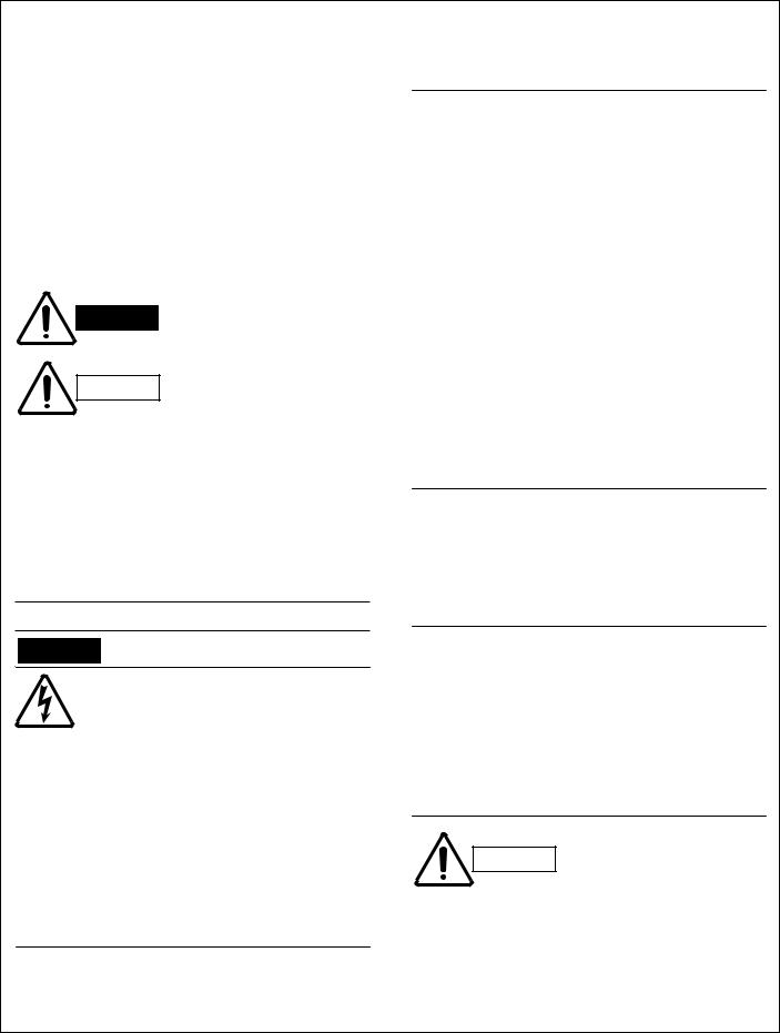
3-1. Unit
3-1-1. Indoor Unit
Indoor unit KGS1411
31-11/16 (805)
10-5/8 (270)
Drain hose ø23/32 (18)
1-5/8 (41.0) |
1-5/8 (41.0) |
3-29/32 |
2-5/16 |
|
|
(99.5) |
(58.5) |
|
Narrow tube ø1/4 (6.35) |
Center of tubing |
Wide tube ø3/8 (9.52) |
hole (2 places) |
6-31/32 (177)
Remote control unit
6-7/32 |
(172.5) |
2-2/5 |
25/32 |
(61)(18.5)
Unit: inch (mm)
9
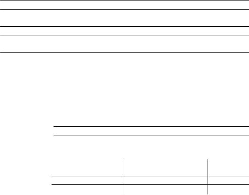
3-1-2. Outdoor Unit
Outdoor unit CG1411
4-11/16 |
16-23/32 |
4-9/16 |
|
(119) |
(425) |
(116) |
|
|
Holes for anchor bolts |
|
2-9/16 |
|
|
(65) |
|
|
(4-ø15/32) |
|
|
|
|
|
|
10-1/4 (260) |
|
|
9-1/16 (230) |
|
|
|
2-13/32 |
|
25-31/32 (660) |
|
(30) |
|
|
|
|
|
|
5-21/32 |
2-17/32 |
|
|
(144) |
(64) |
5-5/32 |
23/32-24(628) |
7/32-23(590) |
|
(131) |
|
Narrow tube service valve
ø1/4 (6.35)
Wide tube service valve ø3/8 (9.52)
9-1/16
(230)
2-21/32 (67.5)
2-5/32 |
(55) |
3-5/16 |
(84) |
Unit: inch (mm)
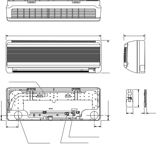
NOTE
Location of Service Valves
Service valves are located behind the side panel. See the illustration at right.
10-1/4
(260)
Wide tube service valve ø3/8 (9.52)
Narrow tube service valve ø1/4 (6.35)
2-1/4 |
(57) |
3-5/16 |
(84) |
10
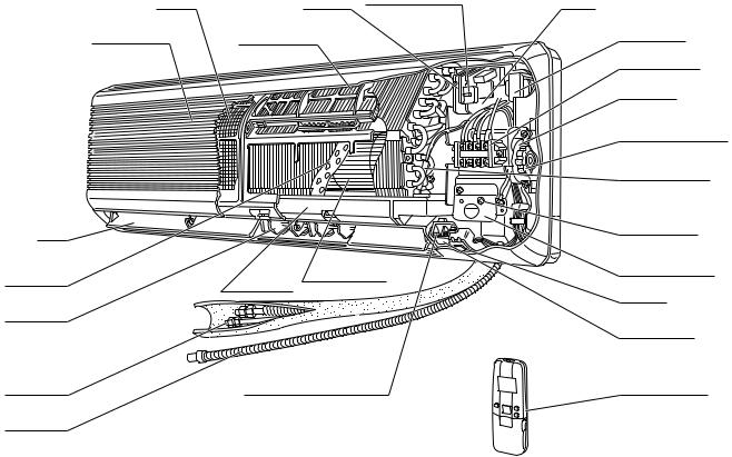
3-2. Internal Components
3-2-1. Indoor Unit
Indoor unit KGS1411
Air filter |
PCB A |
Operation selector |
|
||
Air intake grille |
Air cleaner filter |
|
Flap |
|
|
Heat |
Cross-flow fan |
|
exchanger |
||
Drain pan |
||
|
||
Vertical flap |
|
|
Refrigerant |
|
|
tubing |
Room temperature sensor |
|
Drain hose |
|
PCB B
Transformer
Terminal block
Fan motor
Anti-vibration rubber for motor
Heat-exchanger sensor
Ground screw
Attachment plate of the conduit
Indicator
Louver motor
Wireless remote control unit
11
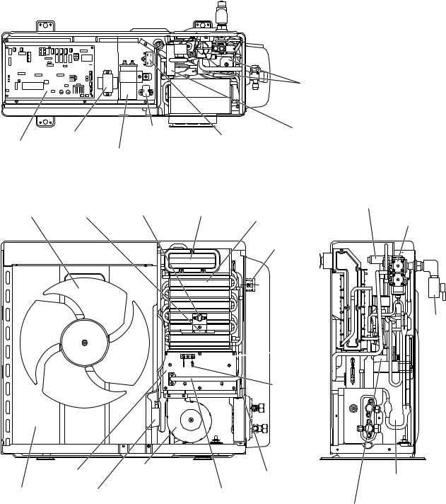
3-2-2. Outdoor Unit
Outdoor unit CG1411
On/Off valve
Transformer |
PTC |
|
|
Reversing |
||
|
Outdoor |
valve |
||||
starter |
|
|||||
Printed |
|
|
fan motor |
|
||
|
Capacitor |
|
|
|||
circuit board |
|
|
capacitor |
|
||
(solid state controller) |
|
for compressor |
|
|
|
|
|
|
Bimetal |
Exhaust |
|
Reversing |
|
Propeller |
Thermal |
Refrigerant |
valve |
|||
thermostat |
chimney |
|||||
fan |
fuse |
Combination |
||||
|
|
heater |
gas valve |
|||
|
|
|
|
|||
|
|
|
|
Terminal |
||
|
|
|
|
block |
||
 Thermistor 2
Manual shut-off valve
Flame  sensor probe
Ignition electrode
Burner |
Combustion |
|
|
|
blower |
Thermistor 1 |
Compressor |
||
|
||||
Heat exchanger |
Ignition transformer |
Gas conduit |
|
|
|
|
|
Accumulator |
12
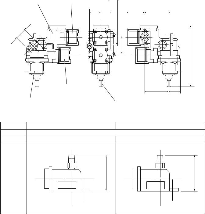
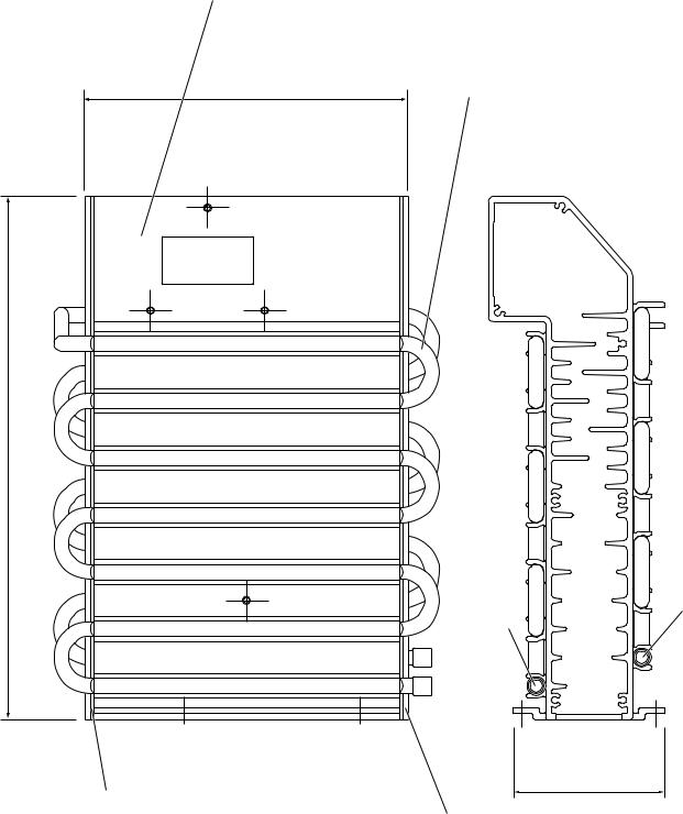
3-3. Major Components
Outdoor unit CG1411
(1) Combination Gas Valve (Proportional Control Valve)
Type: |
Combination Gas Valve |
Model: UP13-27
Material: Aluminum Die-Cast
.945 |
|
0 |
(24) |
|
|
Unit: inch (mm)
|
Electro- |
|
|
|
|
|
|
|
|
|
|
|
|
|
|
|
|
|
|
|
|
|
|
|
magnetic |
|
|
|
|
0.590 |
|
|
|
|
|
|
|
|
|
|
|
|
|
|
|
||
Body |
valve 1 |
|
|
|
|
|
|
|
|
|
|
|
|
|
|
|
|
|
|
|
|||
|
|
|
|
|
(15) |
|
|
|
|
|
|
|
|
|
|
|
|
|
|
|
|||
|
|
|
|
|
|
|
|
|
|
|
|
|
|
|
|
|
|
|
|
|
|||
|
0.906 |
|
0.708 |
|
|
|
|
|
1.433 |
|
|
|
2.067 |
|
|
|
|||||||
|
|
|
|
|
|||||||||||||||||||
|
(23) |
|
(18) |
|
|
|
|
|
|
|
|
|
(36.4) |
|
|
(52.5) |
|
|
|
||||
|
|
|
|
|
|
|
|
|
|
|
|
|
|
|
|
|
|
|
|
|
|
|
|
|
|
|
|
|
|
|
|
|
|
|
|
|
|
|
|
|
|
|
|
|
|
|
|
|
|
|
|
|
|
|
|
|
|
|
|
|
|
|
|
|
|
|
|
|
|
|
|
|
|
|
|
|
|
|
|
|
|
|
|
|
|
|
|
|
|
|
|
|
|
|
|
|
|
|
|
|
|
|
|
|
|
|
|
|
|
|
|
|
|
|
|
|
|
|
|
|
|
|
|
|
|
|
|
|
|
|
|
|
|
|
|
|
|
|
|
|
|
|
|
1.417 (36) |
(124.8) MAX |
|
4.913 |
|
Electro- |
1.948 |
0.925 |
|
magnetic |
||
|
valve 2 |
(49.5) |
(23.5) |
Proportional |
|
Adjuster |
|
control valve |
|
|
|
(2) Gas Nozzle |
|
|
|
|
Natural Gas |
LPG |
|
Material |
Body: Aluminum Die-Cast / Nozzle: Brass |
|
|
Nozzle Dia. |
0.0807 inch (2.05 mm) |
0.0630 inch (1.60 mm) |
|
Figure |
|
|
|
Unit: inch (mm) |
|
|
|
|
1.15 (29.2) |
|
1.15 (29.2) |
|
NAT |
LPG |
|
13
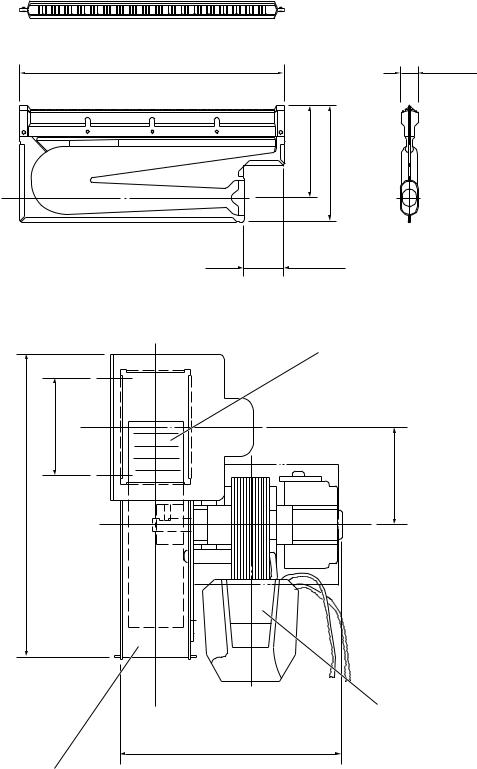
(3)Main Burner
Type: Ribbon Burner
Material: Stainless Steel, Thickness: 0.0157 inch (0.4 mm)
Unit: inch (mm)
6.457 (164) |
0.433 (11) |
2.165 (55) |
2.756 (70) |
0.984 (25)
(4) Combustion Blower
|
|
Combustion blower fan |
|
|
Outer diameter: 3-11/32 |
5.185 (131.7) |
1.578 (40) |
1.597 (40.5) |
Combustion blower motor
FU2-051F1MP
3.764 (95.6)
Fan casing
14
(5) Refrigerant Heater
Aluminum
6.693 (170)
10.827 (275)
Packing (both sides)
Ceramic fiber
Unit: inch (mm)
Copper tube
Outer dia. 5/16
Refrigerant |
outlet |
3.150 (80)
Side wall (both sides) Aluminum-coated steel sheet
Refrigerant inlet
15
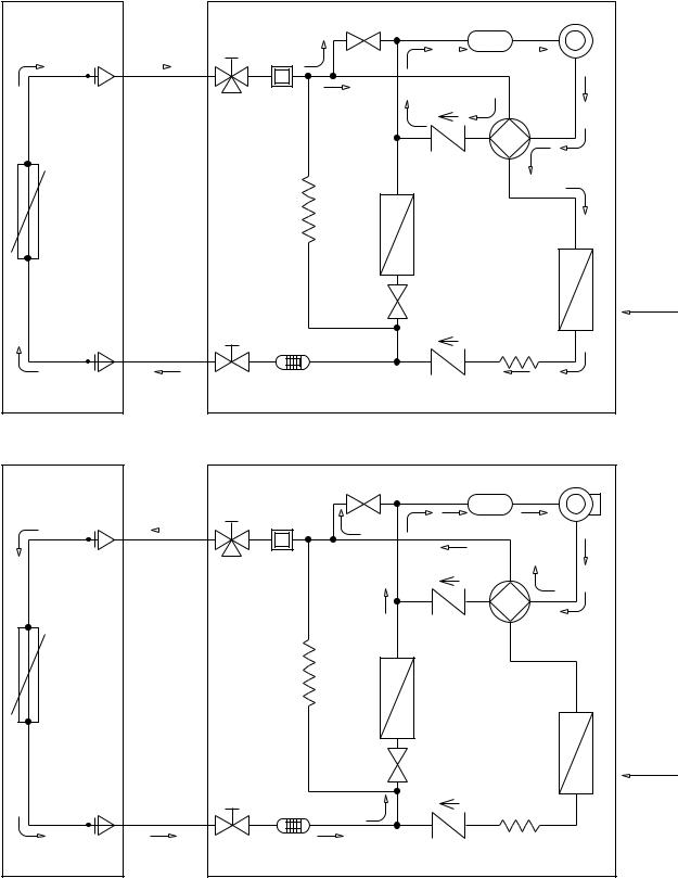
4. REFRIGERANT FLOW DIAGRAM
4-1. Refrigerant Flow Diagram
Indoor unit |
KGS1411 |
Outdoor unit CG1411 |
COOLING CYCLE
Indoor unit
Wide tube |
Wide tube |
||
service valve |
|||
|
|
|
|
O.D.
Muffler
3/8" (9.52 mm)
|
Heat |
Capillary |
|
exchanger |
|
|
tube |
|
|
|
|
|
|
|
|
Narrow tube |
|
service valve |
Narrow tube |
|
O.D. |
Strainer |
1/4" (6.35 mm) |
|
HEATING CYCLE
Indoor unit
Wide tube |
Wide tube |
||
service valve |
|||
|
|
|
|
O.D.
Muffler
3/8" (9.52 mm)
|
Heat |
Capillary |
|
exchanger |
|
|
tube |
|
|
|
|
|
|
|
|
Narrow tube |
|
service valve |
Narrow tube |
|
O.D. |
Strainer |
1/4" (6.35 mm) |
|
Outdoor unit
ON/OFF valve 2 |
Accumulator Compressor |
|||||
|
|
|
|
|
|
|
|
|
|
|
|
|
|
|
|
|
|
|
|
|
|
|
Reversing |
|
( |
) |
valve |
|
|
|
||
Check |
|
|
|
valve 2 |
|
|
|
Refrigerant |
Heat |
|
|
heater |
|
exchanger |
|
ON/OFF |
|
|
|
valve 1 |
|
|
|
( |
) |
|
|
Check |
Capillary tube |
||
valve 1 |
|
|
|
Outdoor unit |
|
|
|
ON/OFF valve 2 |
Accumulator |
Compressor |
|
|
|
Reversing |
|
|
|
valve |
|
( |
) |
|
|
Check |
|
|
|
valve 2 |
|
|
|
Refrigerant |
Heat |
|
|
heater |
|
exchanger |
|
ON/OFF |
|
|
|
valve 1 |
|
|
|
( |
) |
|
|
Check |
Capillary tube |
||
valve 1 |
|
|
|
Cooling cycle
Heating cycle
16
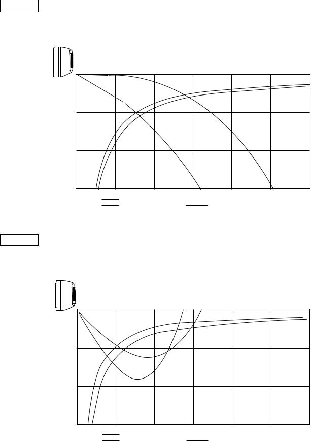
5. PERFORMANCE DATA
5-1. Performance Charts
Indoor unit |
KGS1411 |
Outdoor unit |
CG1411 |
● Cooling Characteristics
|
115 V |
|||||
|
|
|
|
|
|
|
12 |
|
Indoor inlet air |
|
|||
|
° ° |
|
||||
|
|
D.B. temp. F ( C) |
|
|||
(A) |
11 |
|
|
|
|
|
|
|
|
|
|
|
|
90 (32.0) |
|
current |
10 |
|
|
|
|
|
|
|
|
|
|
|
80 (26.7) |
||
|
|
|
|
|
|
||
9 |
|
|
|
|
|
70 (21.0) |
|
Operating |
|
|
|
|
|
|
|
8 |
|
|
|
|
|
|
|
7 |
|
|
|
|
|
|
|
|
|
|
|
|
|
|
|
|
6 |
|
|
|
|
|
|
|
5 |
70 |
80 |
90 |
100 |
110 |
120 |
|
60 |
||||||
|
(15.6)(21.1) (26.7) (32.2) (37.8) (43.3) (48.9) |
||||||
Outdoor inlet air D.B. temp. °F (°C)
● Heating Characteristics
|
|
115 V |
|||||||||||
|
|
|
|
|
|
|
|
|
|
|
|
|
|
|
12 |
|
|
|
|
Indoor inlet air |
|
|
|
||||
|
|
|
|
|
° ° |
|
|
|
|
||||
(A) |
11 |
|
|
|
|
D.B. temp. F ( C) |
|
|
|
|
|||
|
|
|
|
|
|
|
|
|
|
|
|
||
|
|
|
|
|
|
|
|
|
|
|
|
||
|
|
|
|
|
|
|
|
|
|
|
|
|
|
current |
10 |
|
|
|
|
|
|
|
|
|
|
|
|
|
|
|
|
|
|
|
|
|
|
|
|
|
|
Operating |
9 |
|
|
|
|
|
|
|
|
|
|
|
|
|
|
|
|
|
|
|
|
|
|
|
|
||
8 |
|
|
|
|
|
|
|
|
|
|
|
|
|
|
|
|
|
|
|
|
|
|
|
|
|
|
|
|
7 |
|
|
|
|
|
|
|
|
|
|
|
80 (26.7) |
|
|
|
|
|
|
|
|
|
|
|
|
||
|
|
|
|
|
|
|
|
|
|
|
70 (21.0) |
||
|
|
|
|
||||||||||
|
6 |
|
|
|
|
59 (15.0) |
|||||||
|
|
|
|||||||||||
|
|
|
|
|
|
|
|
|
|
|
|
|
|
5
10 20 30 40 50 60 70
(–12.2)(–6.6) (–1.1) (4.4) (10.0) (15.6) (21.1)
Outdoor inlet air D.B. temp. °F (°C)
|
|
|
115 V |
|
|
|
|
|
|
|
115 V |
|
|
|
|
|
||
|
|
150 |
(10.5) |
|
Indoor inlet air |
|
|
|
|
360 (25.4) |
|
Indoor inlet air |
|
|
||||
|
|
|
|
|
D.B. temp. °F (°C) |
|
|
|
|
|
D.B. temp. °F (°C) |
|
|
|||||
|
|
140 |
(9.8) |
|
|
|
|
|
|
|
|
340 (23.9) |
|
|
|
|
|
|
G) |
service valve |
130 |
(9.1) |
|
|
|
|
|
|
G) |
service valve |
320 (22.5) |
|
|
|
|
|
|
|
|
|
|
|
|
|
|
|
|
|
|
|
|
|
||||
2 |
|
|
|
|
|
|
|
|
2 |
|
|
|
|
|
|
|
||
psig (kg/cm |
120 |
(8.4) |
|
|
|
|
|
|
psig (kg/cm |
300 (21.1) |
|
|
|
|
|
80 (26.7) |
||
|
|
|
|
|
|
|
|
|
|
|
70 (21.0) |
|||||||
|
|
|
|
|
|
|
|
|
|
|
|
|
|
|||||
110 |
(7.7) |
|
|
|
|
|
|
280 (19.7) |
|
|
|
|
|
59 (15.0) |
||||
|
|
|
|
|
|
|
|
|
|
|
|
|
|
|
||||
Low pressure |
at wide tube |
100 |
(7.0) |
|
|
|
|
|
|
High pressure |
at wide tube |
260 (18.3) |
|
|
|
|
|
|
90 |
(6.3) |
|
|
|
|
|
90 (32.0) |
240 (16.9) |
|
|
|
|
|
|
||||
|
|
|
|
|
|
|
|
|
|
|
|
|||||||
80 |
(5.6) |
|
|
|
|
|
80 (26.7) |
220 (15.5) |
|
|
|
|
|
|
||||
|
|
|
|
|
|
|
|
|
|
|
|
|||||||
|
|
|
|
|
|
|
|
|
|
|
|
|
|
|
||||
|
|
70 |
(4.9) |
|
|
|
|
|
70 (21.0) |
|
|
200 (14.1) |
|
|
|
|
|
|
|
|
|
|
|
|
|
|
|
|
|
|
|
|
|
|
|||
|
|
60 |
(4.2) |
|
|
|
|
|
|
|
|
180 (12.7) |
|
|
|
|
|
|
|
|
50 |
(3.5) |
|
|
|
|
|
|
|
|
160 (11.2) |
|
|
|
|
|
|
|
|
|
60 |
70 |
80 |
90 |
100 |
110 |
120 |
|
|
10 |
20 |
30 |
40 |
50 |
60 |
70 |
|
|
|
(15.6)(21.1) (26.7) (32.2) (37.8) (43.3) (48.9) |
|
|
(–12.2)(–6.6) (–1.1) |
(4.4) |
(10.0) (15.6) (21.1) |
||||||||||
Outdoor inlet air D.B. temp. °F (°C) |
Outdoor inlet air D.B. temp. °F (°C) |
NOTE
● … Points of rating condition
Black dots in above charts indicate the following rating conditions. Cooling: Indoor air temperature 80°F D.B. / 67°F W.B.
Outdoor air temperature 95°F D.B.
17
5-2. Air Throw Distance Charts
Indoor unit |
KGS1411 |
Cooling
Room air temp.: 80°F (27°C)
Fan speed: High
Horizontal distance (ft.)
5 |
10 |
15 |
20 |
25 |
30 |
Vertical distance (ft.)
Axis air velocity (ft./sec.)
5
10
15
: |
Louver angle 0° |
|
: |
Axis air velocity 0° |
|
||||
: |
Louver angle 30° |
: |
Axis air velocity 30° |
|
Heating
Room air temp.: 70°F (20°C)
Fan speed: High
Vertical distance (ft.)
Axis air velocity (ft./sec.)
Horizontal distance (ft.)
5 |
10 |
15 |
20 |
25 |
30 |
5
10
15
: |
Flap angle 45° |
|
: |
Axis air velocity 45° |
|
||||
: |
Flap angle 60° |
: |
Axis air velocity 60° |
|
18

5-3. Cooling Capacity
Indoor unit |
KGS1411 |
|
|
|
|
|
|
|
|
|
|||
Outdoor unit |
CG1411 |
|
|
|
|
|
|
|
|
|
|
||
115V single-phase 60Hz |
|
|
|
|
|
|
|
|
|
||||
|
|
|
|
|
|
|
|
|
|
|
|
||
|
|
Rating Capacity: 9,000 BTU/h |
|
Air Flow Rate: 282 CFM |
|
|
|||||||
|
|
|
|
|
|
|
|
|
|
|
|
|
|
|
|
Evaporator |
|
|
|
Condenser |
|
|
|
|
|||
|
|
|
|
|
|
|
|
|
|
|
|
||
|
Ent. Temp. |
°F (°C) |
|
|
|
Ambient Temp. °F (°C) |
|
|
|||||
|
|
|
|
|
|
|
|
|
|
|
|
|
|
|
WB |
|
DB |
|
|
75 |
85 |
95 |
|
105 |
115 |
|
|
|
|
|
|
(23.9) |
(29.4) |
(35.0) |
|
(40.6) |
(46.1) |
|
|||
|
|
|
|
|
|
|
|
|
|||||
|
|
|
|
|
TC |
|
9,120 |
8,680 |
8,170 |
|
7,610 |
6,980 |
|
|
|
|
|
|
|
|
|
|
|
|
|
|
|
|
|
|
|
|
CI |
|
0.65 |
0.71 |
0.77 |
|
0.83 |
0.92 |
|
|
59 |
|
72 (22.2) |
SHC |
|
6,750 |
6,530 |
6,280 |
|
6,010 |
5,710 |
|
|
|
|
|
|
|
|
|
|
|
|
|
|
|
|
|
(15.0) |
|
76 (24.4) |
SHC |
|
7,640 |
7,420 |
7,170 |
|
6,900 |
6,600 |
|
|
|
|
|
|
|
|
|
|
|
|
|
|
|
|
|
|
|
|
80 (26.7) |
SHC |
|
8,570 |
8,350 |
8,100 |
|
7,610 |
6,980 |
|
|
|
|
|
|
|
|
|
|
|
|
|
|
|
|
|
|
|
84 (28.9) |
SHC |
|
9,120 |
8,680 |
8,170 |
|
7,610 |
6,980 |
|
|
|
|
|
|
|
|
|
|
|
|
|
|
|
|
|
|
|
88 (31.1) |
SHC |
|
9,120 |
8,680 |
8,170 |
|
7,610 |
6,980 |
|
|
|
|
|
|
|
|
|
|
|
|
|
|
|
|
|
|
|
|
TC |
|
9,460 |
9,040 |
8,590 |
|
8,070 |
7,520 |
|
|
|
|
|
|
|
|
|
|
|
|
|
|
|
|
|
|
|
|
CI |
|
0.65 |
0.72 |
0.78 |
|
0.85 |
0.94 |
|
|
63 |
|
72 (22.2) |
SHC |
|
5,670 |
5,480 |
5,270 |
|
5,040 |
4,800 |
|
|
|
|
|
|
|
|
|
|
|
|
|
|
|
|
|
(17.2) |
|
76 (24.4) |
SHC |
|
6,560 |
6,360 |
6,160 |
|
5,930 |
5,690 |
|
|
|
|
|
|
|
|
|
|
|
|
|
|
|
|
|
|
|
|
80 (26.7) |
SHC |
|
7,490 |
7,290 |
7,090 |
|
6,860 |
6,620 |
|
|
|
|
|
|
|
|
|
|
|
|
|
|
|
|
|
|
|
84 (28.9) |
SHC |
|
8,370 |
8,180 |
7,980 |
|
7,750 |
7,510 |
|
|
|
|
|
|
|
|
|
|
|
|
|
|
|
|
|
|
|
88 (31.1) |
SHC |
|
9,260 |
9,040 |
8,590 |
|
8,070 |
7,520 |
|
|
|
|
|
|
|
|
|
|
|
|
|
|
|
|
|
|
|
|
TC |
|
9,820 |
9,430 |
# 9,000 |
|
8,520 |
8,000 |
|
|
|
|
|
|
|
|
|
|
|
|
|
|
|
|
|
|
|
|
CI |
|
0.66 |
0.72 |
0.79 |
|
0.86 |
0.96 |
|
|
67 |
|
72 (22.2) |
SHC |
|
4,580 |
4,420 |
4,240 |
|
4,050 |
3,840 |
|
|
|
|
|
|
|
|
|
|
|
|
|
|
|
|
|
(19.4) |
|
76 (24.4) |
SHC |
|
5,470 |
5,310 |
5,130 |
|
4,930 |
4,720 |
|
|
|
|
|
|
80 (26.7) |
SHC |
|
6,400 |
6,240 |
6,060 |
|
5,860 |
5,650 |
|
|
|
|
|
|
|
|
|
|
|
|
|
|
|
|
|
|
|
84 (28.9) |
SHC |
|
7,290 |
7,120 |
6,950 |
|
6,750 |
6,540 |
|
|
|
|
|
|
|
|
|
|
|
|
|
|
|
|
|
|
|
88 (31.1) |
SHC |
|
8,180 |
8,010 |
7,830 |
|
7,640 |
7,430 |
|
|
|
|
|
|
|
|
|
|
|
|
|
|
|
|
|
|
|
|
TC |
|
10,340 |
9,980 |
9,590 |
|
9,170 |
8,700 |
|
|
|
|
|
|
|
|
|
|
|
|
|
|
|
|
|
|
|
|
CI |
|
0.67 |
0.73 |
0.8 |
|
0.88 |
0.98 |
|
|
71 |
|
72 (22.2) |
SHC |
|
3,500 |
3,360 |
3,220 |
|
3,060 |
2,890 |
|
|
|
|
|
|
|
|
|
|
|
|
|
|
|
|
|
(21.7) |
|
76 (24.4) |
SHC |
|
4,390 |
4,250 |
4,100 |
|
3,950 |
3,770 |
|
|
|
|
|
|
|
|
|
|
|
|
|
|
|
|
|
|
|
|
80 (26.7) |
SHC |
|
5,320 |
5,180 |
5,030 |
|
4,880 |
4,700 |
|
|
|
|
|
|
|
|
|
|
|
|
|
|
|
|
|
|
|
84 (28.9) |
SHC |
|
6,210 |
6,070 |
5,920 |
|
5,760 |
5,590 |
|
|
|
|
|
88 (31.1) |
SHC |
|
7,090 |
6,960 |
6,810 |
|
6,650 |
6,480 |
|
|
|
|
|
|
|
|
|
|
|
|
|
|
|
|
|
|
|
|
TC |
|
10,550 |
10,210 |
9,850 |
|
9,430 |
8,990 |
|
|
|
|
|
|
|
|
|
|
|
|
|
|
|
|
|
|
|
|
CI |
|
0.68 |
0.74 |
0.81 |
|
0.9 |
1 |
|
|
75 |
|
76 (24.4) |
SHC |
|
3,230 |
3,110 |
2,990 |
|
2,850 |
2,700 |
|
|
|
|
|
|
|
|
|
|
|
|
|
|
|
|
|
(23.9) |
|
80 (26.7) |
SHC |
|
4,160 |
4,040 |
3,920 |
|
3,780 |
3,630 |
|
|
|
|
|
|
|
|
|
|
|
|
|
|
|
|
|
|
|
|
84 (28.9) |
SHC |
|
5,050 |
4,930 |
4,810 |
|
4,660 |
4,520 |
|
|
|
|
|
|
|
|
|
|
|
|
|
|
|
|
|
|
|
88 (31.1) |
SHC |
|
5,930 |
5,820 |
5,690 |
|
5,550 |
5,410 |
|
|
TC |
: Total cooling capacity (BTU/h) |
|
|
|
|
|
|
|||||
|
SHC : Sensible heat capacity (BTU/h) |
|
|
|
|
|
|
||||||
|
CI |
: Compressor input (kW) |
|
|
|
|
|
|
|
||||
|
Rating conditions (# mark) are: Outdoor ambient temperature |
|
95°F (35°C) D.B. |
||||||||||
|
|
|
|
|
Indoor unit entering air temperature |
80°F (26.7°C) D.B./67°F (19.4°C) W.B. |
|||||||
19
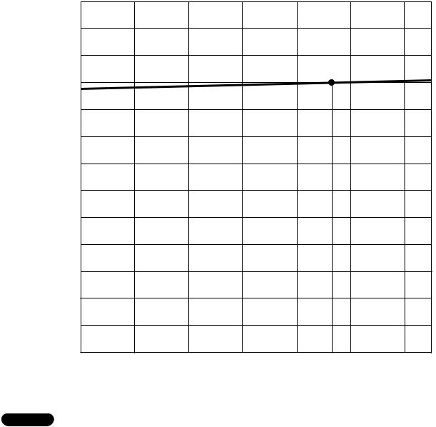
5-4. Heating Capacity
Indoor unit |
KGS1411 |
Outdoor unit |
CG1411 |
Heating capacity ratio %
120 |
|
|
|
|
|
|
|
110 |
|
|
|
|
|
|
|
100 |
|
|
|
|
|
|
|
90 |
|
|
|
|
|
|
|
80 |
|
|
|
|
|
|
|
70 |
|
|
|
|
|
|
|
60 |
|
|
|
|
|
|
|
50 |
|
|
|
|
|
|
|
40 |
|
|
|
|
|
|
|
30 |
|
|
|
|
|
|
|
20 |
|
|
|
|
|
|
|
10 |
|
|
|
|
|
|
|
0 |
|
|
|
|
|
|
|
0 |
10 |
20 |
30 |
40 |
47 |
50 |
60 |
(–17.8) |
(–12.2) |
(–9.4) |
(–1.1) |
(4.4) |
(8.3) |
(10.0) |
(15.5) |
Outdoor temperature °F (°C) D.B.
NOTE
1) ● … Point of rating condition
Black dot in the chart indicates the following rating condition. Indoor: 70°F (21.1°C) D.B.
Outdoor: 47°F (8.3°C) D.B. / 43°F (6.1°C) W.B.
2)Above characteristics indicate instantaneous operation, which does not take into account defrost operation.
3)Fan speed: High
4)Conventional heat pump type air conditioner may not generate enough heating capacity especially when the outdoor temperature falls to extremely low level. Gas heater air conditioner can operate powerfully to warm the room continuously even when the outdoor temperature becomes very low.
20

6. ELECTRICAL DATA
6-1. Electrical Characteristics
Indoor unit |
KGS1411 |
|
|
|
|
|
|
Outdoor unit |
CG1411 |
|
|
|
|
|
|
Cooling |
|
|
|
|
|
|
|
|
|
|
|
|
|
|
|
|
|
|
|
Indoor Unit |
Outdoor Unit |
Complete Unit |
|
|
|
|
|
|
|
|
|
|
|
|
|
Fan Motor |
Fan Motor |
Compressor |
|
|
|
|
|
|
|
|
|
Performance at |
|
|
|
|
115V Single phase 60Hz |
|
|
|
|
|
|
|
|
|
|
Rating conditions |
Running amp. |
A |
0.35 |
0.64 |
7.2 |
8.2 |
|
|
|
Power input |
kW |
0.033 |
0.077 |
0.79 |
0.90 |
|
|
|
|
|
|
|
|
Full load conditions |
Running amp. |
A |
0.35 |
0.64 |
9.0 |
10.0 |
|
|
|
Power input |
kW |
0.033 |
0.077 |
0.99 |
1.10 |
|
|
|
|
|
|
|
|
Rating conditions: Indoor air temperature |
80°F (26.7°C) D.B. / 67°F (19.4°C) W.B. |
Outdoor air temperature |
95°F (35°C) D.B. |
Full load conditions: Indoor air temperature |
95°F (35°C) D.B. / 70°F (21.2°C) W.B. |
Outdoor air temperature |
115°F (46.1°C) D.B. |
Heating
|
|
|
Indoor Unit |
Outdoor Unit |
Complete Unit |
|
|
|
|
|
|
|
|
|
|
|
Fan Motor |
Fan Motor |
Compressor |
|
|
|
|
|
|
|
|
Performance at |
|
|
|
115V Single phase 60Hz |
|
|
|
|
|
|
|
|
|
Rating conditions |
Running amp. |
A |
0.35 |
0.64 |
4.9 |
5.9 |
|
Power input |
kW |
0.033 |
0.077 |
0.51 |
0.62 |
|
|
|
|
|
|
|
Full load conditions |
Running amp. |
A |
0.35 |
0.64 |
5.8 |
6.8 |
|
Power input |
kW |
0.033 |
0.077 |
0.61 |
0.72 |
|
|
|
|
|
|
|
Rating conditions: Indoor air temperature |
70°F (21.1°C) D.B. |
Outdoor air temperature |
47°F (8.3°C) D.B. / 43°F (6.1°C) W.B. |
Full load conditions: Indoor air temperature |
80°F (26.7°C) D.B. |
Outdoor air temperature |
75°F (23.9°C) D.B. / 65°F (18.3°C) W.B. |
21
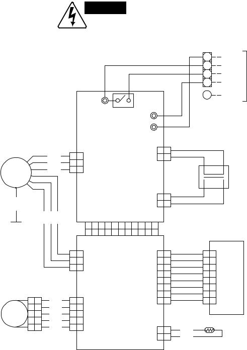
6-2. Electric Wiring Diagrams
(1) Indoor unit |
KGS1411 |
WARNING
To avoid electrical shock hazard, be sure to disconnect power before checking, servicing and/or cleaning any electrical parts.
Fan motor
PNK
BRN
BLU
FM
GRN YEL BLK RED
G
Connector
1 |
1 |
WHT |
2 |
2 |
BLU |
FLP 3 3 |
BLU |
|
4 |
4 |
BLU |
5 |
5 |
BLU |
Flap motor
|
|
|
|
|
|
|
|
|
|
|
|
|
|
Terminal base (4P) |
|
||||||||
|
|
|
|
|
|
|
|
|
|
|
|
|
|
|
|
|
|
1 |
|
|
COM |
unit |
|
|
|
|
|
|
|
|
|
|
|
|
|
|
|
|
|
|
|
2 |
|
|
|
||
|
|
|
|
|
|
|
|
|
|
|
WHT |
|
|
|
|
|
|
|
CM ON |
||||
|
|
|
|
|
|
|
|
|
|
|
|
|
|
|
|
|
|
outdoor |
|||||
|
|
|
|
|
|
|
|
|
|
|
RED |
|
|
|
|
|
4 |
|
|
RV ON |
|||
|
|
|
|
|
|
|
|
|
|
|
|
|
|
|
|
3 |
|
|
AC115V |
|
|||
|
|
|
|
|
|
|
|
|
|
|
|
|
|
|
|
|
|
|
G |
|
|
GND |
To |
|
|
|
|
|
|
|
|
|
|
|
|
|
|
|
|
BLU BLK |
|
|
|
|
|
||
|
|
AC out |
|
|
3 |
4 |
|
RV |
|
|
|
|
|
|
|
|
|
|
|
||||
|
|
|
|
|
|
|
|
|
|
|
|
|
|
|
|
|
|||||||
|
|
|
|
|
|
|
|
|
|
|
|
|
|
|
|
|
|||||||
|
|
|
|
|
Power relay |
|
|
|
|
|
|
|
|
|
|
|
|
||||||
|
|
|
|
|
|
|
|
|
|
|
|
|
|
|
|
|
|
|
|||||
|
|
|
|
|
|
|
|
|
|
COM |
|
|
|
|
|
|
|
|
|
|
|
|
|
|
|
|
|
|
|
|
|
|
Trans 1 |
1 |
1 |
|
|
|
|
|
|
|
|
|
|||
1 |
1 |
|
|
|
|
|
|
|
|
|
WHT |
|
|
|
|
transformer |
|
||||||
Fan |
|
|
|
|
3P (WHT) 3 3 |
|
|
WHT |
|
|
P |
|
|
||||||||||
3 |
3 |
|
|
|
|
|
|
|
|
|
|
|
|
|
|
|
|
|
|
|
|
||
5 |
5 |
5P (WHT) |
|
|
|
|
|
|
|
|
|
|
|
|
|
|
|
|
|
|
|||
|
|
|
|
|
|
|
|
|
|
|
|
|
|
|
|
|
|
||||||
|
|
|
|
Controller (B) |
|
|
|
|
|
|
|
|
|
|
|
|
Power |
|
|||||
|
|
|
|
|
|
|
|
|
|
|
|
|
|
|
|
|
|||||||
|
|
|
|
|
|
|
|
|
|
|
|
|
|
|
|
|
|||||||
|
|
|
|
|
|
|
|
|
Trans 2 |
1 |
1 |
|
|
|
|
|
|
S |
|
|
|||
|
|
|
|
|
|
|
|
|
|
|
BRN |
|
|
|
|
|
|||||||
|
|
|
|
|
|
|
|
|
2P (RED) 2 2 |
|
|
BRN |
|
|
|
|
|
|
|||||
|
|
|
|
|
|
|
|
|
|
|
|
|
|
|
|
|
|
||||||
|
|
|
DC-CONT 11P (WHT) |
|
|
|
|
|
|
|
|
|
|
|
|
||||||||
|
|
1 |
2 |
3 |
4 |
5 |
6 |
7 |
8 |
9 10 11 |
|
|
|
|
|
|
|
|
|
|
|
|
|
|
|
1 |
2 |
3 |
4 |
5 |
6 |
7 |
8 |
9 10 11 |
|
|
|
|
|
|
|
|
|
|
|
|
|
|
|
|
DC-CONT 11P (WHT) |
|
|
|
|
|
|
|
|
|
|
|
|
||||||||
1 |
1 |
|
|
|
|
|
|
|
|
1 |
1 |
|
|
|
1 |
1 |
|
|
|
||||
Hole IC |
|
|
|
|
|
|
|
|
|
WHT |
(WHT)Lamp |
ASSYLAMPIND |
|
||||||||||
2 |
2 |
3P (WHT) |
|
|
|
|
|
|
2 |
2 |
|
|
GRY |
2 |
2 |
|
|||||||
|
|
|
|
|
|
|
|
|
|
|
|||||||||||||
3 |
3 |
|
|
|
|
|
|
3 |
3 |
|
|
GRY |
3 3 |
|
|
|
|||||||
|
|
|
|
|
|
|
|
|
|
Lamp 4 4 |
|
|
GRY |
4 4 |
|
|
|
||||||
|
|
|
|
|
|
|
|
8P (WHT) 5 5 |
|
|
WHT |
5 5 |
|
|
|
||||||||
|
|
|
|
Controller (A) |
|
|
6 |
6 |
|
|
GRY |
6 6 |
|
|
|
||||||||
|
|
|
|
|
|
7 |
7 |
|
|
GRY |
7 7 |
|
|
|
|||||||||
1 |
1 |
|
|
|
|
|
|
|
|
|
|
8 |
8 |
|
|
GRY |
8 |
8 |
|
|
|
||
|
|
|
|
|
|
|
|
|
|
|
|
|
|
|
|
||||||||
2 |
2 |
Flap |
|
|
|
|
|
|
|
|
|
|
|
|
|
|
|
|
|
|
|
|
|
3 |
3 |
5P (GRN) |
|
|
|
|
|
|
|
|
|
|
|
|
|
|
|
|
|
|
|||
4 |
4 |
|
|
|
|
|
|
|
|
|
|
|
|
|
|
|
|
|
|
||||
5 |
5 |
|
|
|
|
|
|
|
|
Coil |
1 |
1 |
|
|
BLK |
|
|
|
|
|
|
||
|
|
|
|
|
|
|
|
|
|
|
|
|
|
|
|
|
|
||||||
|
|
|
|
|
|
|
|
2P (WHT) 2 |
2 |
|
|
BLK |
|
|
|
|
|
|
|||||
|
|
|
|
|
|
|
|
|
|
|
|
|
|
|
|
Coil thermistor |
|
|
|||||
22
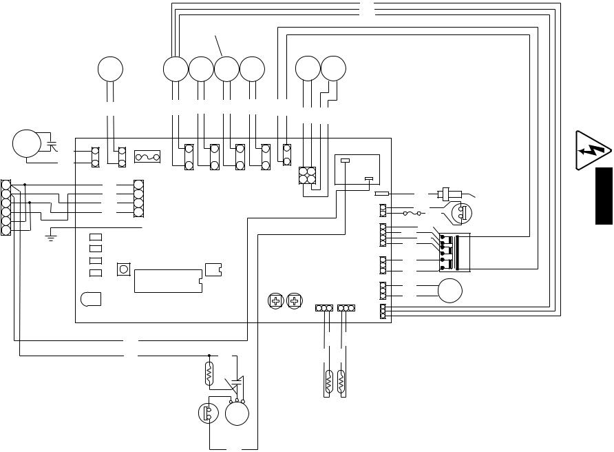
23
BLU
RED
WHT
ON/OFF
Valve 2
Reversing |
Combustion |
ON/OFF |
Ignition |
Gas |
Gas |
valve |
motor |
Valve 1 |
transformer |
valve 1 |
valve 2 |
SV |
|
BM RV1 RV2 |
IG |
GV1 |
GV2 |
BLK BLK |
PUR PUR |
BLK BLK |
BLK BLK |
RED RED |
ORG |
ORG |
WHT |
WHT |
ORG |
ORG |
Fan motor |
|
|
|
|
|
|
|
|
|
|
V |
WHT |
|
|
|
|
|
|
|
|
Power relay (K07) |
||
|
|
|
|
|
|
|
|
|
||||
|
|
|
|
|
|
|
|
|
|
|
|
|
FM |
C |
|
B |
FOI |
|
|
|
|
|
|
|
|
|
BRN |
|
|
|
|
|
|
|
|
|
|
|
|
BRN |
|
|
|
|
|
|
|
H |
|
|
|
Terminal |
BLU |
|
|
|
|
|
|
|
|
|
|
|
(BLU) |
|
(YEL) |
|
|
|
|
|
|
|
|
|
|
block |
|
|
(GRN) |
(BLK) |
(GRY) |
(RED) |
(WHT) |
|
|
|
||
CN02 |
BLKCN03 |
|
|
|
|
|||||||
|
|
|
|
J |
||||||||
1 |
|
CN05 |
CN04 |
CN06 |
CN07 |
CN09 |
|
|
||||
2 |
|
BLU |
|
(WHT) |
D |
E |
F |
G |
I |
|
|
CN17 |
3 |
|
WHT |
|
|
|
|
(WHT) |
|
|
P |
||
|
CN01 |
|
|
|
|
|
|
(WHT) |
||||
4 |
|
RED |
|
|
|
|
|
CN08 |
|
|
||
|
|
|
|
|
|
|
|
|
CN12 |
|||
5 |
|
|
|
|
|
|
|
|
|
|
|
|
|
|
|
CN19 |
|
|
|
|
|
|
|
|
|
6 |
|
|
|
|
|
|
|
|
|
|
(WHT) |
|
|
LD5 |
|
|
|
|
|
|
|
|
|
||
|
|
|
|
|
|
|
|
|
|
|
||
|
|
|
|
|
|
|
|
|
|
|
CN10A |
|
|
|
|
|
|
|
|
|
|
|
|
|
|
|
|
LD4 |
|
|
|
|
|
|
|
|
|
Q1 |
|
|
LD3 |
SWI |
|
ICI |
IC9 |
|
|
|
|
|
(WHT) |
|
|
|
|
|
|
|
|
|
|
|||
|
|
LD2 |
|
|
|
|
|
|
(BLK) |
|
CN10B |
|
|
|
|
|
|
|
|
|
|
Q2 |
|||
|
|
|
|
|
|
|
|
|
CN15 |
|
||
|
|
|
|
|
|
|
|
|
|
(WHT) |
||
|
|
|
|
|
|
|
|
|
(RED) |
|
|
|
|
|
|
|
|
|
|
|
|
|
|
CN11 |
|
|
|
LD1 |
|
|
|
|
|
|
CN16 |
|
|
|
|
|
|
|
|
|
|
|
|
|
0 |
||
|
|
|
|
|
|
|
|
|
|
|
|
|
|
|
|
|
|
|
|
|
VR1 VR2 K |
|
|
M N |
|
|
|
|
WHT |
|
|
|
|
|
BLK |
|
BLK |
(WHT) |
|
|
|
|
|
|
|
|
|
CN14 |
|||
|
|
|
|
|
|
|
|
|
|
|
|
|
|
|
|
BLK |
|
|
BLK |
|
BLK |
BLK |
|
|
|
|
|
|
|
|
|
|
|
|
|
|||
|
|
|
|
|
Start |
|
BLK |
|
|
|
|
|
|
|
|
|
|
relay |
WHT |
|
|
|
|
|
|
|
|
|
|
|
|
|
|
|
|
|
|
|
|
|
|
|
|
PNK |
C |
S |
|
|
|
|
|
|
|
|
|
|
R |
|
|
|
|
|
||
|
|
|
|
Overload |
|
Thermistor 2 |
Thermistor 1 |
|||||
|
|
|
|
|
CM |
|
||||||
|
|
|
|
|
|
|
|
|
|
|||
|
|
|
|
protector |
|
|
|
|
|
|
||
W |
R |
|
Compressor |
||
|
||
|
PNK |
Flame rod
BLK |
|
|
|
WHT |
|
Bimetal |
|
WHT |
|
||
|
thermostat |
||
Thermal fuse |
|
||
|
|
||
RED |
|
|
|
RED |
|
|
|
BLU |
|
|
|
BLU |
|
Power |
|
|
|
||
YEL |
|
transformer |
|
|
|
||
YEL |
|
|
|
BLU |
PV |
Proportional |
|
BLU |
control valve |
||
|
CG1411 unit Outdoor (2)
to sure be hazard, shock electrical avoid To WARNING servicing checking, before power disconnect .parts electrical any cleaning and/or

(3) Printed circuit board |
POW-CG1411 |
K02
|
|
SD1 |
|
CN09 |
1 |
|
|
|
|
CN07 |
|
|
CN06 |
|
|
CN04 |
|
|
CN05 |
|
|
C01 |
|
L01 |
|
|
FUSE 250V/5A |
|
|
|
F01 |
|
CN03 |
1 |
|
|
|
|
CN02 |
1 |
|
|
|
|
K07
D11
CN08
_
+ +
3
C09
J37
 R09
R09
Z01 Z02
3 C102
3 C101
FL |
|
R75 |
R76 |
|
CN12 |
|
CN10A |
|
|
|
CN10B |
|
CN11 |
CN14 |
|
|
|
|||||||
|
|
|
|
|
|
|
|
|
|
|
|
|
|
|
|
|||||||||
|
|
|
|
|
|
|
|
|
|
|
|
|
|
|
|
|
|
|
|
|||||
|
|
|
|
|
|
1 |
|
2 |
1 |
|
4 |
|
|
1 |
|
|
3 |
|
R52 |
|
|
|
|
|
|
CN17 |
|
|
|
|
C02 |
|
|
SD2 |
|
|
|
|
|
|
D03 |
|
|
|
|
|
|
|
|
|
|
R74 |
C27 |
|
|
|
|
|
|
|
|
|
|
R53 |
|
|
|
|
|
|||||
|
|
|
|
|
C28 |
|
|
|
|
|
|
SD3 |
|
|
|
|
C11 |
|
|
|
|
|
||
R105J18 |
R73 |
R72 |
|
J16 |
|
C03 |
C05 |
R50 |
|
C04 |
|
|
|
C32 |
|
C24 |
|
|
CN16CN15 |
|||||
|
R70 |
|
|
|
|
|
|
|
|
|||||||||||||||
|
|
|
|
|
|
|
|
|
+ |
– |
+ |
– |
|
J17 |
|
|
|
C31 |
|
|
|
|
|
|
D14 |
|
|
|
|
|
|
|
|
+ |
– |
+ |
– |
|
|
|
|
|
|
|
|
|
|
|
|
|
|
|
|
|
|
|
|
|
D02 |
|
|
|
|
|
|
|
|
|
|
|
|
|
|
|
|
R81 |
|
|
|
R69 |
|
|
C07 |
|
|
|
Q02 |
|
|
|
|
|
|
L03 |
L02 |
|
|
||
|
|
|
|
|
|
|
|
REG1 |
|
|
|
|
|
|
|
|
|
|
||||||
|
|
|
|
|
|
|
|
|
|
|
|
|
|
|
|
|
|
|
|
|
|
|
|
|
D01 |
|
|
|
|
Q05 |
R71 |
|
|
|
|
|
|
|
|
|
|
|
|
|
R56 |
|
|
||
|
R29 |
|
R80 |
|
|
C06 |
|
|
|
HS1 |
|
HS2 |
|
|
|
|
|
|
||||||
|
|
|
|
|
|
|
|
|
|
|
|
|
|
|
|
|||||||||
|
|
|
|
|
|
|
|
|
|
|
|
|
|
|
|
|
|
|
|
|
|
|
|
|
|
|
Q03 |
|
|
J19 |
|
|
|
|
|
|
|
|
|
|
|
|
|
R55 |
|
|
|||
|
D09 |
C16 |
|
|
|
|
|
|
|
|
|
|
|
|
R17 |
|
|
|
|
|||||
K01 |
R28 |
J15 |
|
J14 |
|
|
|
|
|
R13 |
|
|
|
|
VR2 |
|
|
|||||||
|
|
|
|
|
|
|
|
|
|
|
|
|
R12 |
|
|
C12 |
|
|
|
|
– |
|
|
|
|
|
|
|
|
|
|
|
|
|
|
|
|
|
|
|
|
|
|
|
|
|
|||
|
|
D10 |
|
R32 |
|
|
|
|
|
|
|
|
|
|
|
|
|
|
|
|
HIGH |
|
||
|
|
|
|
|
|
|
Q07 |
|
|
|
|
|
IC3 |
|
R16 |
|
|
+ |
|
|||||
|
R78 |
|
|
|
|
|
|
|
|
|
|
|
|
|
|
|
|
|||||||
|
|
|
|
|
Q06 |
|
|
D05 |
R68 |
|
R14 |
|
|
|
|
|
|
|
|
|
|
|||
|
|
|
|
|
|
|
|
|
|
|
|
|
|
|
|
|
|
|
|
|
|
|
||
K03 |
|
|
|
|
R31 |
R23 |
|
R25 |
|
R67 |
|
R20 |
|
|
|
|
|
|
|
|
|
|||
|
|
|
|
|
|
|
|
|
|
|
|
R19 |
|
R18 |
|
|
|
|||||||
|
D16 |
|
|
Q04 |
|
|
|
R65R66 |
|
|
|
R104 |
|
VR1 – LO |
98 |
|||||||||
|
|
|
|
|
|
|
|
|
|
|
|
|
||||||||||||
|
D12 |
|
|
|
|
|
|
|
|
C33 |
|
|
|
|
|
|
|
|
|
|
|
|
|
|
|
|
|
|
|
|
|
|
|
|
|
|
|
|
|
|
|
|
|
|
|
|
|
|
|
K06 |
|
|
|
|
|
|
|
|
|
|
|
|
J13 |
C08 |
|
|
|
|
|
|
|
|
||
|
|
|
|
|
|
|
|
|
|
|
|
|
|
|
|
|
|
|
|
|
||||
|
|
|
|
|
|
|
|
|
|
|
|
|
|
|
|
|
|
|
|
|
|
|
||
|
|
|
|
|
|
C14 |
IC2 |
|
|
|
|
|
J21 |
|
|
|
|
R103 |
+ |
|
|
|||
|
|
|
|
|
|
|
|
|
C26 |
|
|
|
|
|
|
|
|
|
||||||
K04 |
|
|
|
|
|
|
|
|
|
|
|
|
|
|
|
R15 |
|
|
||||||
|
|
|
|
|
|
|
|
|
|
|
|
|
|
|
|
|
|
|
|
|
|
|
|
|
|
|
|
|
|
|
|
|
|
|
|
|
|
|
C13 |
R21 |
|
C20 |
|
|
|
J12 |
|
|
|
|
D13 |
R60 |
R79 |
D07 |
J20 |
|
|
J23 |
|
J22 |
|
|
J11 |
|
|
|
|
C100 |
|
|
||||
|
|
|
|
|
|
|
|
|
|
|
|
|
|
|
|
|
|
|
|
|
|
|
||
TR1 |
|
|
|
|
|
|
|
|
|
|
R48 |
|
|
|
|
IC8 |
|
|
|
|
|
|
|
|
|
|
|
|
|
|
|
|
|
|
|
|
|
|
|
|
|
|
|
|
R24 |
|
|
|
J24 |
|
|
|
|
|
|
|
|
|
|
R26 |
|
|
|
|
|
|
|
|
|
|
|
|
|
|
|
|
|
|
|
|
|
J25 |
|
IC9 |
|
|
J09 |
|
C19 |
|
|
|
||
|
|
|
|
|
|
|
|
|
|
|
|
|
|
|||||
|
|
|
|
|
|
|
|
|
|
|
|
|
|
|
|
|||
|
|
|
R27 |
|
|
|
J10 |
|
|
|
D17 |
|
|
|
|
|
||
|
|
C10 |
|
|
|
|
|
|
|
|
|
|
|
|
|
|||
|
|
|
|
|
D04 |
|
|
|
C29 |
|
C14 |
J08 |
|
|
||||
|
|
D08 |
|
|
|
|
|
|
|
|
|
|
||||||
|
|
|
D06 |
|
|
|
|
|
|
|
|
|
|
|
|
|
|
|
R07 |
|
|
|
|
|
|
J26 |
|
|
|
J27 |
|
|
|
|
|
|
|
R10 |
|
C15 |
|
|
|
R82 |
RA1 |
|
|
|
R64 |
|
|
|
|
|||
|
|
|
|
|
|
|
|
|
|
|
|
|||||||
|
|
|
|
|
|
|
|
|
|
|
|
|
|
|
|
|
|
|
|
|
|
|
|
R59 |
|
|
|
|
|
J28 |
|
|
|
R63 |
|
|
|
|
|
|
|
|
|
|
|
|
|
|
|
|
|
|
|
|||
R06 |
|
|
|
|
|
|
|
|
|
|
|
|
|
C25 |
|
|
||
|
|
|
|
|
|
|
|
|
|
|
|
|
|
R46 |
T13V-TD |
|||
|
|
PC3 |
|
J06 |
|
|
IC5 |
IC1 |
|
|
|
|
R57 |
|||||
|
|
|
|
|
|
|
|
|
C21 |
|||||||||
|
|
|
|
R22 |
|
|
|
|
|
|
|
|
|
|
|
|||
|
|
|
|
|
|
|
|
|
|
J07 |
|
|
|
R83 |
|
|
||
|
|
|
|
|
|
|
|
|
|
|
|
|
C22 |
|
|
|||
|
|
|
GND |
|
R30 |
|
J32 |
|
|
|
R54 OSC |
|
C104 |
XX2- |
||||
ABS1 |
|
|
|
|
|
|
|
|
|
|
||||||||
|
|
|
|
|
|
|
|
|
|
|
|
|
|
|
|
|
4FF4B10002710 |
|
CN01 |
|
CN19 |
|
|
IC7 |
J05 |
J33 |
R101 R100 |
R102 |
SW1 |
C103 |
R58 |
C105 |
|
|
CN21 |
||
|
|
|
|
J04 |
|
|
|
|
|
J29 |
|
J31 |
R51 |
R47 |
|
|||
J36 |
|
|
R84 |
|
|
|
|
|
|
|
|
|
D100 |
|
|
|
||
R04 |
|
|
|
|
|
|
|
|
|
|
J30 |
|
|
|
|
|
|
|
|
|
|
R40 |
|
|
|
|
|
|
|
|
|
|
|
|
|
|
|
|
|
|
|
|
|
|
|
|
|
|
|
|
|
|
|
|
|
|
|
|
|
C18 |
|
|
|
|
|
|
|
R49 |
|
|
|
|
|
|
|
|
|
|
R41 |
|
|
|
|
|
|
|
|
|
|
|
|
|
|
|
|
|
|
|
|
|
|
|
|
|
|
|
|
|
R106 |
|
|||
R03 |
PC2 |
R39 |
|
|
|
|
|
|
|
|
|
|
|
|
||||
|
J01 |
J35 |
J34 |
|
LO/HIGH |
J02 |
|
|
|
|
|
|
|
|
||||
|
|
PC1 |
C17 |
|
|
|
|
|
|
|
|
|
|
|||||
|
|
|
|
|
|
|
|
|
|
|
|
|
|
|
|
|
|
|
|
|
|
R38 |
|
|
|
|
|
|
|
|
J03 |
|
|
|
|
||
R02 |
|
|
|
|
|
|
|
|
|
IC6 |
|
|
|
|
|
|
||
|
|
|
|
|
|
|
|
|
|
|
|
|
|
|
|
|
||
|
|
|
|
|
|
|
|
|
|
|
|
|
|
|
|
|
|
|
K05 |
D15 |
LD5 |
LD4 |
LD3 |
R37 |
R36 |
R35 |
R34 |
R33 |
LD1 |
R01 |
|
LD2 |
|
|
|
|
|
24
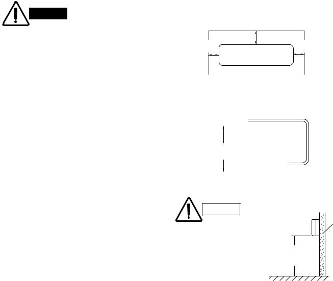
7. INSTALLATION INSTRUCTIONS
7-1. Installation Site Selection
7-1-1. Indoor Unit
WARNING
AVOID:
To prevent abnormal heat generation and the possibility of fire, do not place obstacles, enclosures and grilles in front of or surrounding the air conditioner in a way that may block air flow.
2"(5 cm) min.
2"(5 cm) 2"(5 cm) min. min.
Front View
●direct sunlight.
●nearby heat sources that may affect performance of the unit.
●areas where leakage of flammable gas may be expected.
●places where large amounts of oil mist exist.
DO:
●select an appropriate position from which every corner of the room can be uniformly cooled. (High on a wall is best.)
●select a location that will hold the weight of the unit.
●select a location where tubing and drain hose have the shortest run to the outside.
●allow room for operation and maintenance as well as unrestricted air flow around the unit. (Fig. 1)
●install the unit within the maximum elevation difference (H) above the outdoor unit and within a total tubing length (L) from the outdoor unit as detailed in Table 1 and Fig. 2.
Table 1
|
|
Fig. 1 |
|||||||||||
|
|
|
Tubing length (L) |
||||||||||
|
INDOOR |
|
|||||||||||
|
UNIT |
|
|
|
|
|
|
|
|
|
|
|
|
|
Elevation |
|
|
|
|
|
|
|
|
|
|
|
|
|
|
|
OUTDOOR |
|
|||||||||
|
difference (H) |
|
|
|
|||||||||
|
|
|
UNIT |
|
|||||||||
|
|
|
|
|
|||||||||
|
|
|
|
|
|
|
|
|
|
|
|
|
|
Fig. 2
CAUTION
For stable operation of the air conditioner, do not install wall-mounted type indoor units under 5 ft. (1.5 m) from floor level.
Indoor unit
Wall
Minimum height from floor level 5 ft. (1.5 m)
Floor level
Fig. 3
|
Max. Allowable Tubing |
Min. Allowable Tubing |
Limit of Tubing |
Limit of Elevation |
Required Amount of |
Model |
Length at Shipment |
Length at Shipment |
Length (L) |
Difference (H) |
Additional Refrigerant |
|
ft. (m) |
ft. (m) |
ft. (m) |
ft. (m) |
oz./ft. (g/m)* |
|
|
|
|
|
|
CG1411 |
25 (7.5) |
13 (4) |
49 (15) |
23 (7) |
0.27 (15) |
|
|
|
|
|
|
*If total tubing length becomes 25 to 49 ft. (7.5 to 15 m) (max.), charge additional refrigerant (R22) by 0.27 oz./ft. (15 g/m). No additional compressor oil is necessary.
25
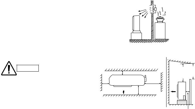
7-1-2. Outdoor Unit
AVOID:
●heat sources, exhaust fans, etc. (Fig. 4)
●damp, humid or uneven locations.
DO:
●choose a place as cool as possible.
●choose a place that is well ventilated.
●allow enough room around the unit for air intake/ exhaust and possible maintenance. (Fig. 5a)
CAUTION
●Install the outdoor unit above snowfall line.
●Do not place objects on or sit on the outdoor unit. Also, never block the air intake/outlet or exhaust. Distortion of the outdoor unit or incomplete combustion may result.
●Touching the air exhaust can cause a burn. Take special care for children not to touch it.
●Do not introduce foreign matter into the air intake/outlet or exhaust. Do not insert pointed objects, such as sticks.
●When the ambient temperature is dropping, a white cloud or fog may be seen blowing from the unit. This does not indicate a problem.
●The distance between any building opening* and the exhaust must be 24 in. (60 cm) or more.
●Locate the outdoor unit away from windows to avoid possible entry of exhaust gases into the building. Pay special attention to the windows of a neighboring house or building.
●If there is a window within 24 in. (60 cm) of the exhaust, make sure it is not located inside the projected exhaust area within 24 in. (60 cm) above, within 6 in. (15 cm)
below, within 6 in. (15 cm) on either side, or within 6 in. (15 cm) in front of the exhaust.
* Meaning of “building opening”
Windows or doors which can be opened, but not including those which are fixed or cannot be opened.
NO |
Exhaust fan |
Hot air
Heat source
Outdoor unit
Fig. 4
|
|
|
|
Obstacle above |
|||
|
|
|
(25 cm) |
discharge |
Min. |
Min. |
|
Air intake |
Min. 6" (15 cm) |
7 ft. |
7 ft. |
||||
Valve side |
|
||||||
|
|
|
|
(2 m) |
(2 m) |
||
|
|
|
Min. 10" |
|
|
Obstacle |
|
Min. 6" Air discharge |
Min. 12" |
Air |
|
||||
(15 cm) |
|
(30 cm) |
|
|
|
||
|
|
|
|
Ground |
|
|
|
|
|
|
|
|
Min. 6 in. |
||
|
|
Fig. 5a |
|
(15 cm) |
|||
|
|
|
Air intake |
||||
|
|
|
|
|
|||
26
 Loading...