


User Manual
QM49F QM55F QM65F
SMT-4933
The color and the appearance may differ depending on the product, and the specifications are subjectto changewithout priornoticeto improvethe performance.
Recommended hours of use per day of this product is under 24 hours.
Ifthe product is usedforlongerthan 24 hours a day,thewarrantymaybevoid.

Table of contents
Before Using the Product
Copyright |
5 |
|
|
Safety Precautions |
6 |
Symbols |
6 |
Cleaning |
6 |
Storage |
7 |
Electricity and Safety |
7 |
Installation |
8 |
Operation |
10 |
Preparations
Checking the Components |
13 |
Components |
13 |
|
|
Parts |
14 |
Control Panel |
14 |
Reverse Side |
16 |
Anti-theft Lock |
17 |
Remote Control |
18 |
Connection Using an IR Stereo Cable |
|
(sold separately) |
20 |
|
|
Before Installing the Product |
|
(Installation Guide) |
21 |
Tilting Angle and Rotation |
21 |
Ventilation |
21 |
|
|
Installing the Wall Mount |
23 |
Installing the Wall Mount |
23 |
Wall Mount Kit Specifications (VESA) |
23 |
Remote Control (RS232C) |
24 |
Cable Connection |
24 |
Connection |
27 |
Control Codes |
28 |
Connecting and Using aSourceDevice
Before Connecting |
37 |
Pre-connection Checkpoints |
37 |
|
|
Connecting to a PC |
37 |
Connection Using an HDMI Cable |
37 |
Connection Using an DPCable |
38 |
Connection using a DVI cable (Digitaltype) |
38 |
Connection Using an HDMI-DVI Cable |
39 |
Connection usingthe DVI-RGB cable |
39 |
|
|
Connecting to a Video Device |
40 |
Connection Using an HDMI-DVI Cable |
40 |
Connection Using an HDMI Cable |
41 |
|
|
Connecting to an Audio System |
41 |
Attaching the Network box (Sold separately) 42
Connecting the Network box |
|
(Sold separately) |
43 |
MagicInfo |
43 |
|
|
Changing the Input source |
45 |
Source |
45 |
Using MDC
MDC Program Installation/Uninstallation |
46 |
Installation |
46 |
Uninstallation |
46 |
|
|
Connecting to MDC |
47 |
Using MDCvia RS-232C (serial data |
|
communications standards) |
47 |
Using MDCvia Ethernet |
48 |
Home feature
Multi Screen |
50 |
|
|
Picture Mode |
51 |
|
|
On/Off Timer |
52 |
On Timer |
52 |
Off Timer |
52 |
|
|
Network Settings |
54 |
|
|
MagicInfo Player I |
55 |
|
|
ID Settings |
56 |
Device ID |
56 |
PC Connection Cable |
56 |
|
|
Video Wall |
57 |
Video Wall |
57 |
|
|
More settings |
59 |
2

Table of contents
ScreenAdjustment
Picture Mode |
60 |
|
|
Backlight / Brightness / Contrast / |
61 |
Sharpness / Color / Tint (G/R) |
|
|
|
Color Temperature |
62 |
|
|
White Balance |
62 |
|
|
Gamma |
63 |
|
|
Calibrated Value |
63 |
|
|
Picture Options |
64 |
Color Tone |
65 |
Digital NR |
65 |
HDMI Black Level |
65 |
Film Mode |
66 |
Dynamic Backlight |
66 |
|
|
Picture Size |
67 |
Picture Size |
67 |
Zoom/Position |
68 |
Resolution |
68 |
|
|
Auto Adjustment |
69 |
|
|
PC Screen Adjustment |
69 |
|
|
Picture Off |
70 |
|
|
Reset Picture |
70 |
OnScreen Display
Multi Screen |
71 |
Multi Screen |
71 |
|
|
Display Orientation |
76 |
Onscreen Menu Orientation |
76 |
Source Content Orientation |
76 |
Aspect Ratio |
76 |
|
|
Screen Protection |
77 |
Pixel Shift |
77 |
Timer |
78 |
Immediate Display |
79 |
Side Gray |
79 |
|
|
Message Display |
79 |
Source Info |
79 |
No Signal Message |
79 |
MDC Message |
79 |
|
|
Menu Language |
80 |
|
|
Reset OnScreen Display |
80 |
System
Setup |
81 |
Initial settings (System) |
81 |
|
|
Time |
82 |
Clock Set |
82 |
DST |
82 |
Sleep Timer |
82 |
PowerOn Delay |
82 |
|
|
MagicInfo I Source |
83 |
|
|
Auto Source Switching |
84 |
Auto Source Switching |
84 |
Primary Source Recovery |
84 |
Primary Source |
84 |
Secondary Source |
84 |
|
|
Power Control |
85 |
Auto PowerOn |
85 |
PC Module Power |
85 |
StandbyControl |
86 |
Network Standby |
86 |
PowerButton |
86 |
|
|
Eco Solution |
87 |
Energy Saving |
87 |
Eco Sensor |
87 |
Screen Lamp Schedule |
88 |
No Signal PowerOff |
88 |
Auto PowerOff |
88 |
|
|
Temperature Control |
89 |
|
|
Change PIN |
89 |
3

Table of contents
General |
90 |
Security |
90 |
HDMI Hot Plug |
90 |
|
|
Reset System |
91 |
SoundAdjustment
HDMI Sound |
92 |
|
|
Sound on Video Call |
93 |
|
|
Speaker Selection |
93 |
|
|
Reset Sound |
94 |
Support
Software Update |
95 |
|
|
Contact Samsung |
95 |
|
|
Go to Home |
95 |
|
|
Reset All |
95 |
TroubleshootingGuide
Requirements Before Contacting Samsung |
|
Customer Service Center |
96 |
Testing the Product |
96 |
Checking the Resolution and Frequency |
96 |
Checkthefollowings. |
97 |
|
|
Q & A |
104 |
Specifications
General |
106 |
|
|
Preset Timing Modes |
108 |
Appendix
Responsibility for the Pay Service (Cost to |
|
Customers) |
111 |
Not a product defect |
111 |
AProduct damage caused bycustomer's |
|
fault |
111 |
Others |
111 |
|
|
Optimum Picture Quality and Afterimage |
|
Burn-in Prevention |
112 |
Optimum Picture Quality |
112 |
Prevention ofAfterimage Burn-in |
112 |
|
|
License |
114 |
|
|
Terminology |
115 |
4

Chapter 01
Before Using the Product
Copyright
The contents ofthis manual are subjectto changewithout noticeto improve quality.
© 2016 Samsung Electronics
Samsung Electronics ownsthe copyrightforthis manual.
Use orreproduction ofthis manual in parts orentiretywithoutthe authorization of Samsung Electronics is prohibited.
Microsoft,Windows are registeredtrademarks of Microsoft Corporation.
VESA, DPM and DDC are registered trademarks of the Video Electronics Standards Association.
Ownership of all othertrademarks is attributedtotheirdue owner.
•• An administrationfee maybe charged if either
––(a) an engineer is called out at your request and there is no defect in the product
(i.e.whereyou havefailedto readthis usermanual).
––(b)you bringthe unitto a repaircenterandthere is no defect inthe product (i.e.whereyou havefailedto readthis usermanual).
•• The amount of such administration chargewill be advisedtoyou before anywork orhomevisit is carried
out.
5

Safety Precautions
Caution
RISK OF ELECTRIC SHOCK DO NOT OPEN
Caution : TO REDUCE THE RISK OF ELECTRIC SHOCK, DO NOT REMOVE COVER. (OR BACK) THERE ARE NO USER SERVICEABLE PARTS INSIDE.
REFER ALL SERVICING TO QUALIFIED PERSONNEL.
This symbol indicatesthat highvoltage is present inside.
It is dangerousto make anykind of contactwith anyinternal part ofthis product.
This symbol alertsyouthat important literature concerning operation and maintenance has been includedwiththis product.
Symbols
Warning
Aserious orfatal injurymayresult if instructions are notfollowed.
Caution
Personal injuryordamageto properties mayresult if instructions are notfollowed.
Activities marked bythis symbol are prohibited.
Instructions marked bythis symbol must befollowed.
Cleaning
――Exercisecarewhen cleaningasthe panelandexteriorofadvancedLCDsareeasilyscratched. ――Takethefollowing stepswhen cleaning.
――Thefollowing images areforreference only. Real-life situations maydifferfromwhat is shown inthe images.
1 |
Poweroffthe product and computer. |
2 |
Disconnectthe powercordfromthe product. |
――Holdthe powercable bythe plug and do nottouchthe cablewith wet hands. Otherwise, an electric shock mayresult.
3 Wipethe productwith a clean, soft and drycloth.
•• Do not use detergentsthat contain alcohol, solvent
orsurface-active agents.
!
•• Do not spraywaterordetergent directlyonthe
product.
4 Wet a soft and drycloth inwaterandwringthoroughlyto clean
the exterior of the product.
5 |
Connectthe powercordtothe productwhen cleaning is |
|
finished. |
6 |
Poweronthe product and computer. |
6
Storage
Duetothe characteristics of high-glossyproducts, using a UVhumidifiernearbymaycreate white-colored stains onthe product.
――Contact CustomerService Centerifthe inside ofthe product needs cleaning (servicefeewill be charged).
Electricity and Safety
――Thefollowing images areforreference only. Real-life situations maydifferfromwhat is shown inthe images.
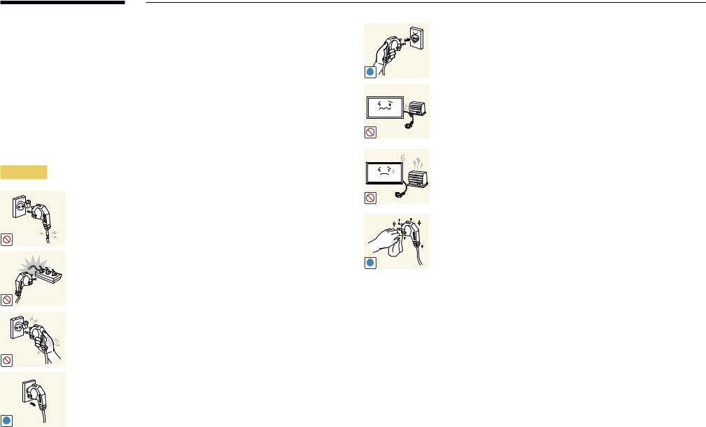
Warning
Do not use a damaged powercord orplug, ora loose powersocket.
•• An electric shock or fire may result.
Do not use multiple productswith a single powersocket.
•• Overheated powersockets maycause afire.
Do nottouchthe powerplugwithwet hands. Otherwise, an electric shock may result.
Insertthe powerplug allthewayin so it is not loose.
•• An unsecure connection may cause a fire.
!
Connectthe powerplugto a grounded powersocket (type1 insulated devices only).
•• An electric shock orinjurymayresult.
!
Do not bend orpullthe powercordwithforce. Be careful notto leave the powercord undera heavyobject.
•• Damage to the cord may result in a fire or electric shock.
Do not placethe powercord orproduct nearheat sources.
•• A fire or electric shock may result.
Clean anydust aroundthe pins ofthe powerplug orthe powersocket with a drycloth.
•• A fire may result.
!
7
Caution
!
!
!
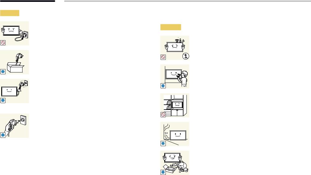
Do not disconnectthe powercordwhilethe product is being used.
•• The product maybecome damaged byan electric shock.
Onlyusethe powercord providedwithyourproduct bySamsung. Do not usethe powercordwith otherproducts.
•• A fire or electric shock may result.
Keepthe powersocketwherethe powercord is connected unobstructed.
•• The powercord must be disconnectedto cut off powertothe productwhen an issue occurs.
•• Notethatthe product is not completelypowered down byusing onlythe powerbutton onthe remote.
Holdthe plugwhen disconnectingthe powercordfromthe power socket.
•• An electric shock or fire may result.
Installation
Warning
DO NOT PLACE CANDLES, INSECT REPELLANTS OR CIGARETTES ON TOP OF THE PRODUCT. DO NOT INSTALL THE PRODUCT NEAR HEAT SOURCES.
•• A fire may result.
Have atechnician installthewall-mount hanger.
•• Installation byan unqualified person can result in an injury.
•• Onlyuse approved cabinets.
!
Do not installthe product in poorlyventilated spaces such as a bookcase orcloset.
•• An increased internal temperature may cause a fire.
Installthe product at least10 cm awayfromthewallto allow ventilation.
•• An increased internal temperature may cause a fire.
!
Keep the plastic packaging out of the reach of children.
•• Children may suffocate.
!
8
! |
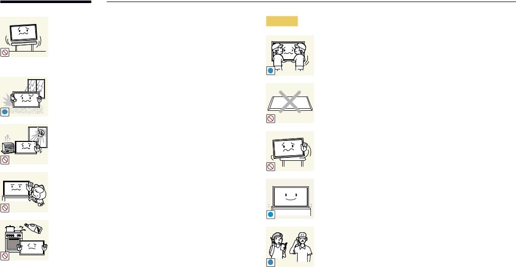
Do not installthe product on an unstable orvibrating surface
(insecure shelf, sloped surface, etc.)
•• The product mayfall and become damaged and/orcause an injury.
•• Usingthe product in an areawith excessvibration maydamage the product or cause a fire.
Do not installthe product in avehicle ora place exposedto dust, moisture (waterdrips, etc.), oil, orsmoke.
•• A fire or electric shock may result.
Do not exposethe productto direct sunlight, heat, ora hot object such as a stove.
•• The product lifespan maybe reduced orafire mayresult.
Do not installthe productwithinthe reach ofyoung children.
•• The product mayfall and injure children.
•• Asthefront is heavy, installthe product on aflat and stable
surface.
Edible oil, such as soybean oil, can damage ordeformthe product. Do not install the product in a kitchen or near a kitchen counter.
Caution
!
!
SAMSUNG 
!
Do not dropthe productwhile moving.
•• Productfailure orpersonal injurymayresult.
Do not set downthe product on itsfront.
•• The screen maybecome damaged.
When installingthe product on a cabinet orshelf, make surethatthe bottom edge ofthefront ofthe product is not protruding.
•• The product mayfall and become damaged and/orcause an injury.
•• Installthe product onlyon cabinets orshelves ofthe right size. Set downthe product gently.
•• Productfailure orpersonal injurymayresult.
Installing the product in an unusual place (a place exposed to a lot of fine dust, chemical substances, extremetemperatures ora significant presence of moisture, ora placewherethe productwill operate continuously for an extended period of time) may seriously affect its performance.
•• Be sureto consult Samsung CustomerService Centerifyouwant to install the product at such a place.
9
Operation
Warning
There is a highvoltage insidethe product. Neverdisassemble, repair or modify the product yourself.
•• A fire or electric shock may result.
•• Contact Samsung CustomerService Centerforrepairs.
!
Before movingthe product,turn offthe powerswitch and disconnect the powercable and all otherconnected cables.
•• Damage to the cord may result in a fire or electric shock.
!
!
Ifthe product generates abnormal sounds, a burning smell orsmoke,
disconnectthe powercord immediatelyand contact Samsung
CustomerService Center.
•• An electric shock or fire may result.
!
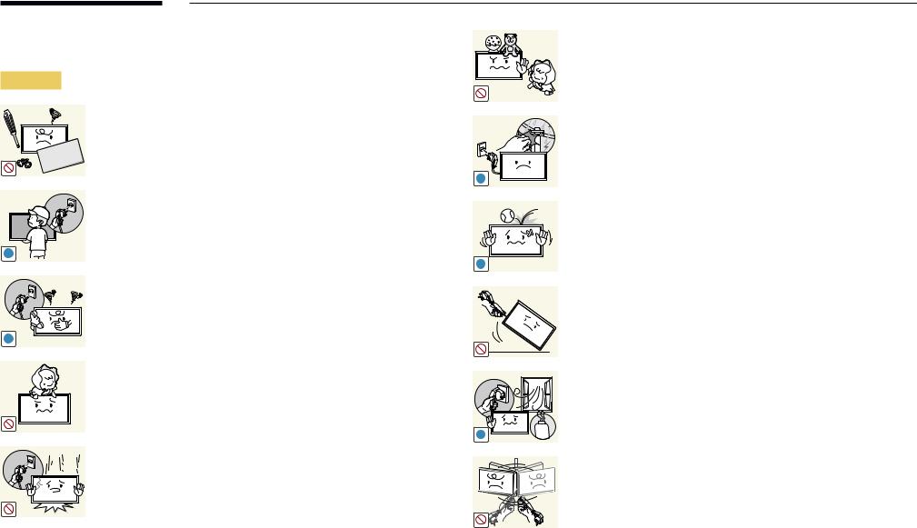
Do not let children hangfromthe product orclimb ontop of it.
•• Children maybecome injured orseriouslyharmed.
!
If the product is dropped or the outer case is damaged, turn off the powerswitch and disconnectthe powercord. Then contact Samsung CustomerService Center.
•• Continued use can result in a fire or electric shock.
Do not leave heavyobjects oritemsthat children like (toys, sweets, etc.) on top of the product.
•• The product orheavyobjects mayfall as childrentryto reachfor thetoys orsweets resulting in a serious injury.
During a lightning orthunderstorm, poweroffthe product and removethe powercable.
•• A fire or electric shock may result.
Do not drop objects onthe product orapplyimpact.
•• A fire or electric shock may result.
Do not movethe product bypullingthe powercord oranycable.
•• Product failure, an electric shock or fire may result from a damaged cable.
If a gas leakage isfound, do nottouchthe product orpowerplug.
Also,ventilatethe area immediately.
•• Sparks can cause an explosion or fire.
GAS
Do not lift ormovethe product bypullingthe powercord orany cable.
•• Product failure, an electric shock or fire may result from a damaged cable.
10
Do not use orkeep combustible sprayoran inflammable substance near the product.
•• An explosion or fire may result.
!
Ensurethevents are not blocked bytablecloths orcurtains.
•• An increased internal temperature may cause a fire.
|
Do not insert metallic objects (chopsticks, coins, hairpins, etc) or |
100 |
objectsthat burn easily(paper,matches, etc) intothe product (viathe |
|
vent orinput/output ports, etc). |
•• Be sureto poweroffthe product and disconnectthe power cordwhenwaterorotherforeign substances have enteredthe product. Then contact Samsung CustomerService Center.
•• Product failure, an electric shock or fire may result.
Do not place objects containing liquid (vases, pots, bottles, etc) or metallic objects ontop ofthe product.
•• Be sureto poweroffthe product and disconnectthe power cordwhenwaterorotherforeign substances have enteredthe product. Then contact Samsung CustomerService Center.
•• Product failure, an electric shock or fire may result.
Caution
!
-_-
!
!
!
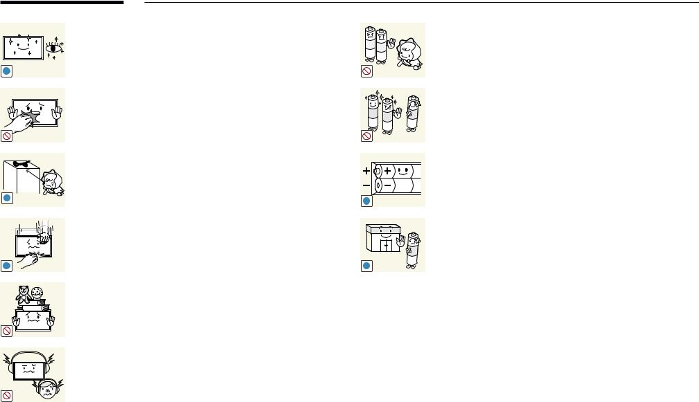
Leavingthe screenfixedon astationaryimageforan extendedperiod oftime maycause afterimage burn-in ordefective pixels.
•• Activate power-saving mode ora moving-picture screen saverif youwill not be usingthe productforan extended period oftime.
Disconnectthe powercordfromthe powersocket ifyou do not plan on usingthe productforan extended period oftime (vacation, etc).
•• Dust accumulation combinedwith heat can cause afire, electric shock or electric leakage.
Use the product at the recommended resolution and frequency.
•• Your eyesight may deteriorate.
Do not holdthe product upside-down ormove it byholdingthe stand.
•• The product mayfall and become damaged orcause an injury.
Looking at the screen too close for an extended period of time can deteriorate your eyesight.
Do not use humidifiers orstoves aroundthe product.
•• A fire or electric shock may result.
11
Restyoureyesformorethan 5 minutesforevery1 hourof product use.
•• Eyefatiguewill be relieved.
!
Do nottouchthe screenwhenthe product has beenturned onforan extended period oftime as itwill become hot.
Store small accessories out of the reach of children.
!
Exercise cautionwhen adjustingthe product angle orstand height.
•• Yourhand orfingermayget stuck and injured.
•• Tiltingthe product at an excessive angle maycausethe product
tofall and an injurymayresult.
!
Do not place heavyobjects onthe product.
•• Productfailure orpersonal injurymayresult.
When using headphones orearphones, do notturnthevolumetoo high.
•• Havingthe soundtoo loud maydamageyourhearing.
Be carefulthat children do not placethe batteryintheirmouths when removedfromthe remote control. Placethe batteryin a location that children or infants cannot reach.
•• If children have hadthe batteryintheirmouths, consultyour doctor immediately.
When replacingthe battery, insert itwiththe right polarity(+, -).
•• Otherwise,the batterymaybecome damaged orit maycause
fire, personal injuryordamage dueto leakage ofthe internal
liquid.
Use onlythe specified standardized batteries, and do not use a new batteryand a used batteryatthe sametime.
•• Otherwise,the batteries maybe damaged orcausefire, personal injuryordamage dueto a leakage ofthe internal liquid.
!
The batteries (and rechargeable batteries) are not ordinaryrefuse and must be returnedforrecycling purposes. The customeris responsibleforreturningthe used orrechargeable batteriesfor recycling.
! |
•• The customercan return used orrechargeable batteriesto a |
|
nearbypublic recycling centerorto a store sellingthe same |
|
type ofthe batteryorrechargeable battery. |
12
Chapter 02
Preparations
––Contactthevendorwhereyou purchased the product if any components are missing.
––The appearance of the components maydifferfromtheimagesshown.
––Astandisnotprovidedwiththe product. To install a stand, you can purchase one separately.
––TheRS232Cadaptercanbeusedto connect to another monitor using the
D-SUB(9-pin)typeRS232Ccable.
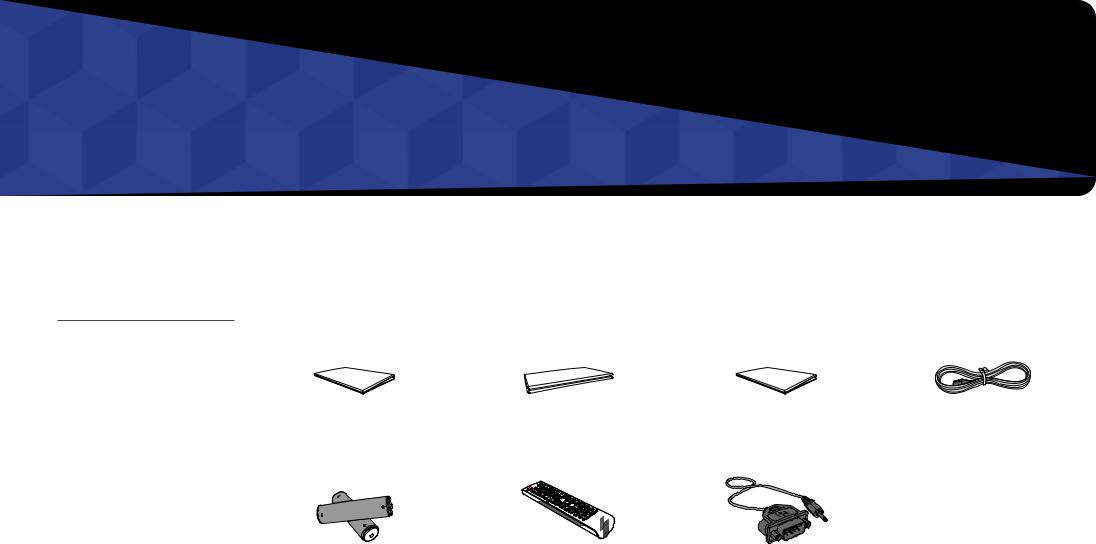
Checking the Components
Components
――Components may differ in different locations.
Quick setup guide |
|
Warranty card |
Regulatory guide |
Powercord |
||
|
(Notavailableinsomelocations) |
|||||
|
|
|
|
|
||
|
|
|
|
|
|
|
Batteries |
Remote Control |
RS232C(IN) adapter |
|||
(Not available in some locations) |
|||||
|
|
|
|||
|
|
|
|
|
|
13
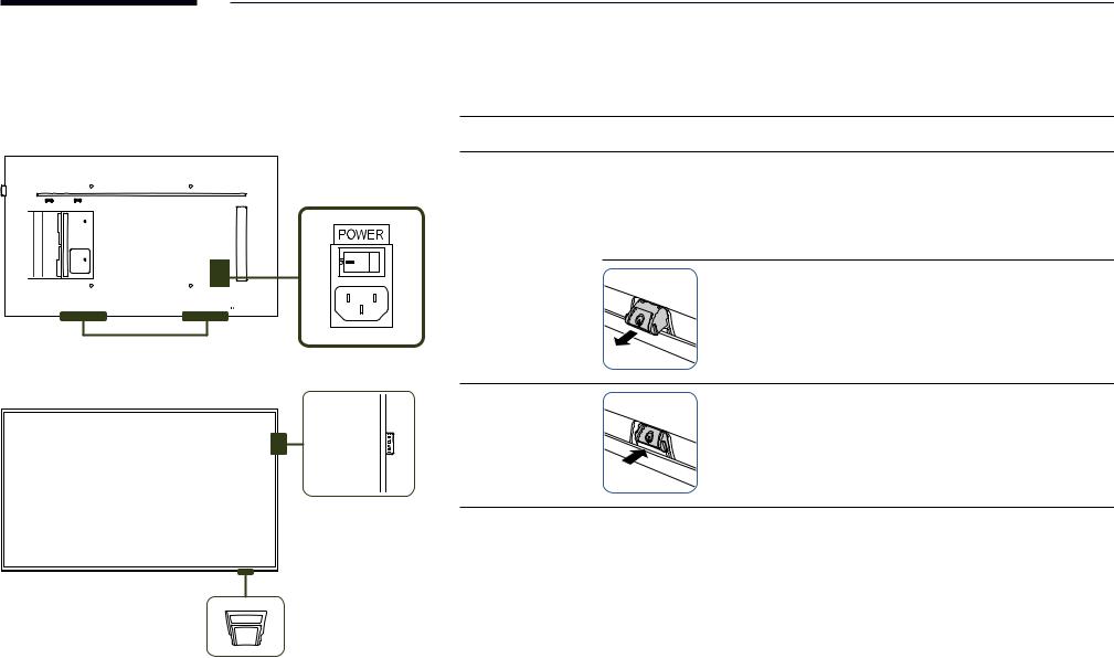
Parts
Control Panel
Speaker
――The colorand shape of parts maydifferfromwhat is shown. Specifications are subjectto changewithout notice to improve quality.
Parts Description
Spacer logo |
Do not pull onthe spacerlogo usingforce. The logo maytearorbreak off. |
Press a button onthe remote control pointing atthe bottom ofthe productfaceto performthefunction. The remote control sensoris located onthe bottom ofthe product.
――Using otherdisplaydevices inthe same space asthe remote control ofthis product can causethe otherdisplaydevicesto be inadvertentlycontrolled.
Remote sensor
To use remote/eco sensor, make sure the sliding panel key is protrudingfromthe bottom ofthe product.
Panel Key |
To use the panel key, make sure the sliding panel key is not |
|
protrudingfromthe bottom ofthe product. |
||
|
Spacer logo
Usethe remote controlwithin 7 mto10 mfromthe sensoronthe product at an angle of 30 from the left and right. ――Store used batteries out of reach of children and recycle.
――Do not use a newand used batterytogether. Replace both batteries atthe sametime. ――Remove batterieswhenthe remote control is notto be usedforan extended period oftime.

 Remote sensor &
Panel Key
14
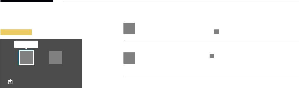
――The panel keyis located onthe bottom rightfront ofthe product.
――If you press the P button onthe panel keywhenthe product isturned on,the control menuwill be displayed.
Control menu
PowerOff
 Press:Move
Press & Hold: Select
Buttons |
|
Description |
|
|
|
|
|
|
|
|
|
|
|
|
Poweroffthe product. |
|
|
|
|
Power Off |
Withthe control menu screen displayed, brieflypressthe panel keyto move |
||
|
|
|
the cursor to Power Off |
|
, and then press and hold the panel key to turn off |
|
|
|
|
||
|
|
|
the product. |
|
|
|
|
Select the connected input source. |
||
|
|
Withthe control menu screen displayed, brieflypressthe panel keyto move |
||
|
|
|||
|
Source |
the cursor to Source |
|
, and then press and hold the panel key to display the |
|
|
|||
|
input source screen. |
|||
|
|
|||
|
|
With the input source screen displayed, press and hold the panel key to |
||
|
|
switchtothe desired input source. |
||
――The panel keycan onlybe usedforPower Off and Source.
――To exitfromthe control menu screen,waitfor3 seconds ormorewithout pressingthe panel key.
15
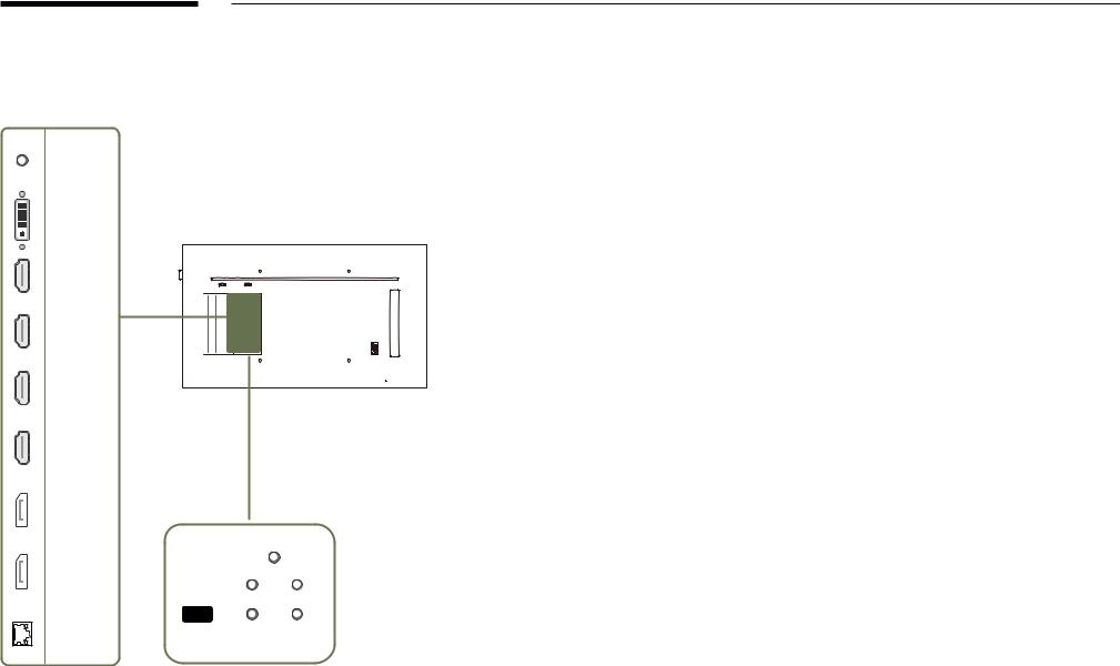
Reverse Side
――The colorand shape of parts maydifferfromwhat is shown.
Specifications are subjectto changewithout noticeto improve quality.
RS232C IN |
|
|
DVI/PC/ |
|
|
MAGICINFO IN |
|
|
HDMI IN 4 |
|
|
HDMI IN 3 |
|
|
HDMI IN 2 |
|
|
HDMI IN 1 |
|
|
DP IN 2 |
|
|
(UHD 60Hz) |
|
|
|
RS232C |
|
|
|
OUT |
DP IN 1 |
|
OUT IR |
(UHD 60Hz) |
IR IN |
|
|
||
|
SERVICE |
|
RJ45 |
DVI/PC/ |
AUDIO OUT |
HDMI/ |
|
|
|
AUDIO IN |
|
Port |
Description |
|
|
|
|
RS232C IN |
Connects to MDC using an RS232C adapter. |
|
|
|
|
DVI/PC/MAGICINFO IN |
DVI: Connectsto a source device using a DVI cable orHDMI-DVI cable. |
|
|
PC: Connects a D-SUB cable (via a DVI-RGB adapter) ora DVI-RGB cableto a |
|
|
PC. |
|
|
MAGICINFO IN: To use MagicInfo, make sureto connectthe DP-DVI cable. |
|
|
|
|
HDMI IN1, HDMI IN 2, HDMI IN 3, |
Connectsto a source device using a HDMI cable orHDMI-DVI cable. |
|
HDMI IN 4 |
――Obtain sharp picture qualitywhenviewing UHD content at 30Hz. |
|
DP IN 2 (UHD 60Hz) |
Connectsto a PC using a DPcable. |
|
|
――Obtain sharp picture qualitywhenviewing UHD content at 60Hz. |
|
DP IN1 (UHD 60Hz) |
||
|
||
|
|
|
RJ45 |
Connectsto MDC using a LAN cable. |
|
|
|
|
RS232C OUT |
Connects to MDC using an RS232C adapter. |
|
|
|
|
IR IN |
Supplies powertothe external sensorboard orreceivesthe external remote |
|
|
control sensor signal. |
|
|
|
|
IR OUT |
Receivesthe remote control signalviathe external sensorboard and outputs |
|
|
the signalvia LOOPOUT. |
|
|
|
|
SERVICE |
Connectsto a USB devicewhen upgrading software. |
|
|
|
|
DVI/PC/HDMI/AUDIO IN |
Receives soundfrom a PCvia an audio cable. |
|
|
|
|
AUDIO OUT |
Connectstothe audio of a source device. |
|
|
|
16

Anti-theft Lock
――An anti-theft lock allowsyouto usethe product securelyeven in public places.
――The locking device shape and locking method depend onthe manufacturer. Refertothe user guide providedwithyouranti-theft locking devicefordetails.
――Thefollowing images areforreference only. Real-life situations maydifferfromwhat is shown inthe images.
To lock an anti-theft locking device:
1
2
3
4
Fixthe cable ofyouranti-theft locking deviceto a heavyobject such as a desk.
Put one end ofthe cablethroughthe loop onthe otherend.
Insertthe locking device intothe anti-theft lock slot atthe back ofthe product.
Lockthe locking device.
––An anti-theft locking device can be purchased separately.
––Refertothe userguide providedwithyouranti-theft locking devicefordetails.
––Anti-theft locking devices can be purchased at electronics retailers oronline.
17
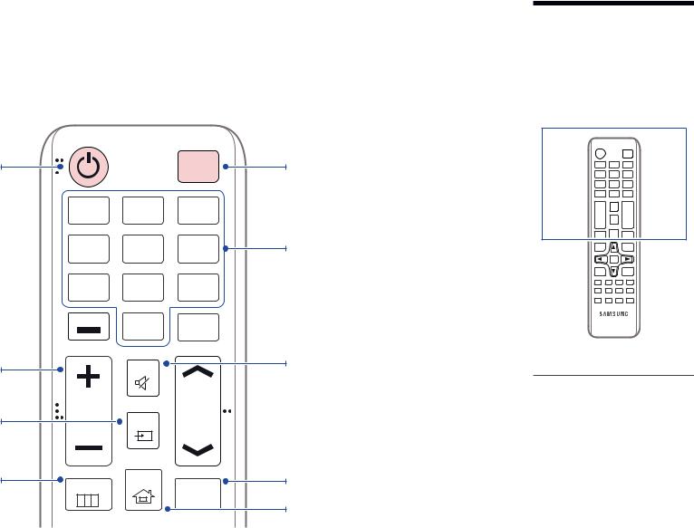
Remote Control
――Using otherdisplaydevices inthe same space asthe remote control ofthis product can causethe otherdisplaydevicesto be inadvertentlycontrolled. ――Abuttonwithout a description inthe image belowis not supported onthe product.
Powerontheproduct.
Adjustthevolume.
Change the input source.
Display or hide the onscreen display menu, or returntothepreviousmenu.
|
|
POWER |
|
|
|
OFF |
|
.QZ |
ABC |
DEF |
|
1 |
2 |
3 |
|
GHI |
JKL |
MNO |
|
4 |
5 |
6 |
|
PRS |
TUV |
WXY |
|
7 |
8 |
9 |
|
DEL-/-- |
SYMBOL |
|
|
0 |
CH LIST |
||
|
|||
|
|
||
|
MUTE |
|
|
VOL |
SOURCE |
CH |
|
|
|
MENU |
HOME |
MagicInfo |
|
||
|
|
Player I |
Poweroffthe product.
Numberbuttons
Enterthe password inthe OSD menu.
Mute the sound.
Unmuting the sound: Press MUTE again or pressthevolume control(+VOL-) button.
Use this hotkey to directly access MagicInfo.
This hotkeyis availablewhen a network box is connected.
Go to Home Launch Button.
––Remote control buttonfunctions may differ for different products.
18

Quickly select frequently used functions. |
TOOLS |
INFO |
|
|
Returntothepreviousmenu. |
RETURN |
|
|
EXIT |
|
|
|
|
|
|
PC |
DVI |
HDMI |
DP |
|
A |
B |
C |
D |
It sets safe lock function. |
IR control |
|
|
|
If multiple products are connected through the |
SET |
UNSET |
LOCK |
|
Video Wall feature, press the SET buttonand |
|
|
|
|
enteraproductIDusingthenumberbuttons. |
|
|
|
|
Control the product using the remote control. |
|
|
|
|
CancelavaluethathasbeensetusingtheSET |
|
|
|
|
buttonandcontrolallconnectedproducts |
|
|
|
|
using the remote control. |
|
|
|
|

 Displayinformation aboutthe current input
source.
Movetothe upper, lower, left orright menu, 
 oradjust an option's setting.
Confirm a menu selection. Exit the current menu.
Manually select a connected input source from PC, DVI, HDMI1, HDMI2, HDMI3, HDMI4, DisplayPort1 or DisplayPort2.
To place batteries in the remote control
––Remote control buttonfunctions may differ for different products.
19
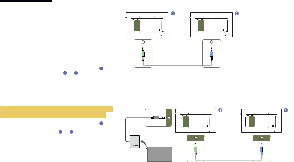
Connection Using an IR Stereo Cable (sold separately)
Make sureto connectthe external remote control sensorwhilethe product is powered off. Then, poweronthe product.
|
|
|
IR OUT |
|
IR IN |
|
|
|
|
|
|
||
Controlling more than one display product using |
|
|
||||
|
|
|
|
|
||
|
|
|
|
|
||
your remote control |
|
|
|
|
|
|
•• Connect the IR OUT port on the product to the IR IN port on the other |
|
|
|
|
||
displayproduct usingthe dedicated stereo cable. |
|
|
|
|
||
•• A command sent from the remote control pointed at product 1 will |
|
|
|
|
||
be received byboth displayproducts 1 and 2 . |
|
|
|
|
||
――The appearance may differ depending on the product.
Controlling more than one display product using an external remote control sensor (sold separately)
•• A command sent from the remote control pointed at product 1
(towhichthe external remote control sensoris connected)will be received byboth displayproducts 1 and 2 .
――The appearance may differ depending on the product.
IR IN
IR OUT |
IR IN |
20
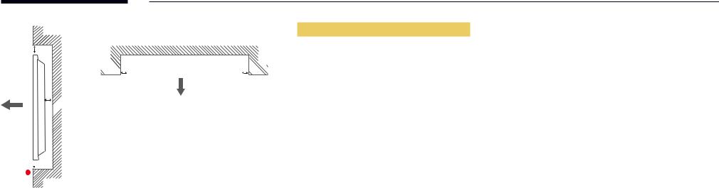
Before Installing the Product
(Installation Guide)
15 ˚
A 
B
Figure1.1 Side view
To prevent injury,this apparatus must be securelyattachedtothefloor/wall in accordancewiththe installation instructions.
•• Ensurethat an authorized installation companyinstallsthewall mount.
•• Otherwise, it mayfall and cause personal injury.
•• Make sureto installthe specifiedwall mount.
Tilting Angle and Rotation
――Contact Samsung CustomerService Centerforfurtherdetails.
•• The product can betilted at a maximum angle of15 from a perpendicularwall surface.
•• To usethe productvertically(portrait),turn it clockwise sothatthe LED is pointing down.
Ventilation
Installation on a Perpendicular Wall
A Minimum 40 mm
B Ambienttemperature: Under35 C
C
•• When installingthe product on a perpendicularwall, allowat least 40 mm of space betweenthe product and wall surfaceforventilation and ensurethatthe ambientAtemperature is kept below35 C.
C.
21
B |
A 
 C
C
E |
Figure1.2 Side view
Figure1.3 Side view

 D
D  D
D 

Installation on an Indented Wall
――Contact Samsung CustomerService Centerforfurtherdetails.
Plane view
A Minimum 40 mm B Minimum 70 mm C Minimum 50 mm D Minimum 50 mm
E Ambienttemperature: Under35 C
C
――When installingthe product on an indentedwall, allowat leastthe space specified above betweenthe product andwallforventilation and ensurethatthe ambienttemperature is kept below35 C.
C.
22
Installing the Wall Mount
Installing the Wall Mount
The wall mount kit (sold separately) allows you to mount the product on the wall.
For detailed information on installing the wall mount, see the instructions provided with the wall mount. We recommend you contact a technician for assistance when installing the wall mount bracket.
Samsung Electronics is not responsible for any damage to the product or injury to yourself or others if you elect to install the wall mount on your own.
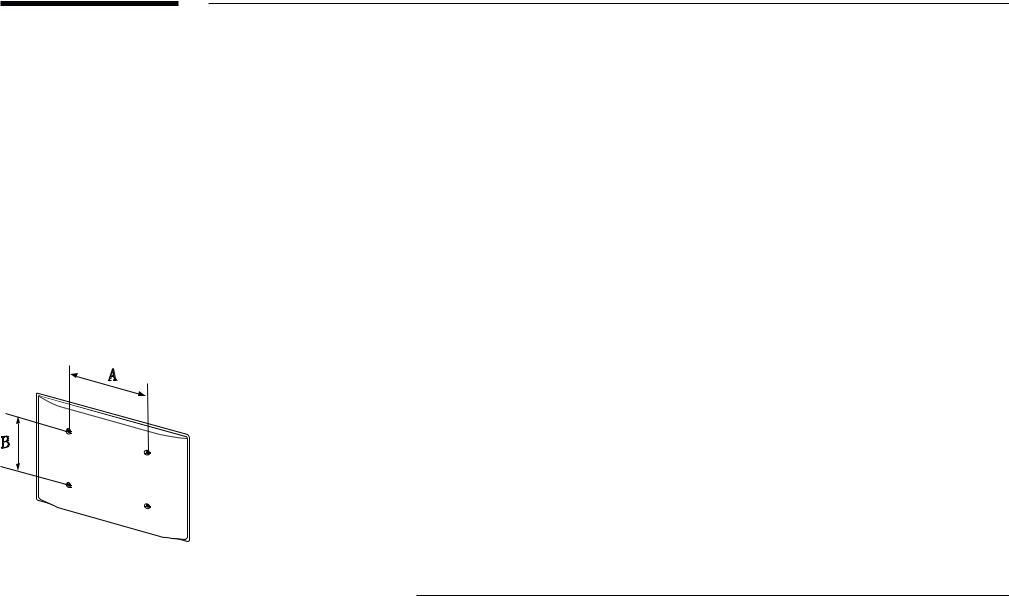
WallMountKitSpecifications(VESA)
――Install your wall mount on a solid wall perpendicular to the floor. Before attaching the wall mount to surfaces other than plaster board, please contact your nearest dealer for additional information.
If you install the product on a slanted wall, it may fall and result in severe personal injury.
•• Samsung wall mount kits contain a detailed installation manual and all parts necessary for assembly are provided.
•• Do not use screws that are longer than the standard length or do not comply with the VESA standard screw specifications. Screws that are too long may cause damage to the inside of the product.
•• For wall mounts that do not comply with the VESA standard screw specifications, the length of the screws may differ depending on the wall mount specifications.
•• Do not fasten the screws too firmly. This may damage the product or cause the product to fall, leading to personal injury. Samsung is not liable for these kinds of accidents.
•• Samsung is not liable for product damage or personal injury when a non-VESA or non-specified wall mount is used or the consumer fails to follow the product installation instructions.
•• Do not mount the product at more than a 15 degree tilt.
•• Always have two people mount the product on a wall.
•• Standard dimensions for wall mount kits are shown in the table below.
|
|
|
Unit: mm (inches) |
|
Model name |
VESAscrewholespecs(A*B) |
StandardScrew |
Quantity |
|
|
inmillimeters |
|
|
|
|
|
|
|
|
QM49F / QM55F / QM65F / |
400 × 400 (15.7 × 15.7) |
M8 |
4 |
|
SMT-4933 |
||||
|
|
|
――Do not install your Wall Mount Kit while your product is turned on. It may result in personal injury due to electric shock.
23
Remote Control (RS232C)
Cable Connection
RS232C Cable
Interface |
RS232C (9 pins) |
|
|
Pin |
TxD (No.2), RxD (No.3), GND (No.5) |
|
|
Bit rate |
9600 bps |
|
|
Data bits |
8 bit |
|
|
Parity |
None |
|
|
Stop bit |
1 bit |
|
|
Flow control |
None |
|
|
Maximum length |
15 m (only shielded type) |
|
|
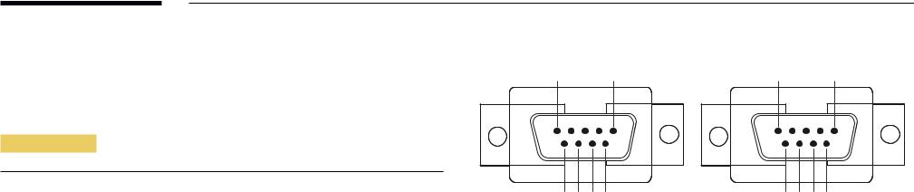
•• Pin assignment
1 |
2 |
3 |
4 |
5 |
5 |
4 |
3 |
2 |
1 |
|||||||||||
|
|
|
|
|
|
|
|
|
|
|
|
|
|
|
|
|
|
|
|
|
|
|
|
|
|
|
|
|
|
|
|
|
|
|
|
|
|
|
|
|
|
|
|
|
|
|
|
|
|
|
|
|
|
|
|
|
|
|
|
|
|
|
|
|
|
|
|
|
|
|
|
|
|
|
|
|
|
|
|
|
|
|
|
|
|
|
|
|
|
|
|
|
|
|
|
|
|
|
|
|
|
|
|
|
|
|
|
|
|
|
|
|
|
|
|
|
|
|
|
|
|
|
|
|
|
6 |
7 |
8 |
9 |
9 |
8 |
7 |
6 |
<Male type> |
<Female type> |
||||||
Pin |
Signal |
|
|
1 |
Detect data carrier |
|
|
2 |
Received data |
|
|
3 |
Transmitted data |
|
|
4 |
Prepare data terminal |
|
|
5 |
Signal ground |
|
|
6 |
Prepare data set |
|
|
7 |
Send request |
|
|
8 |
Clear to send |
|
|
9 |
Ring indicator |
|
|
24
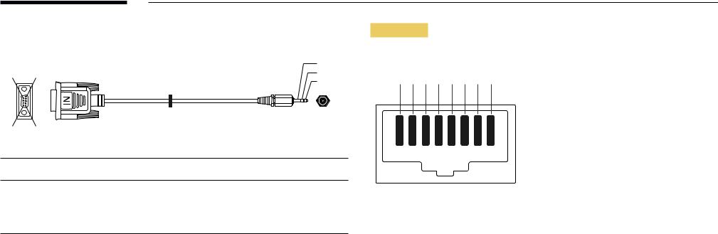
•• |
RS232C cable |
|
|
|
|
|
Connector: 9-Pin D-Subto Stereo Cable |
|
|
|
|
|
|
|
|
|
3 |
6 |
1 |
|
|
|
2 |
|
|
|
1 |
||
|
|
|
|
|
|
|
|
|
|
|
-P2- |
9 |
5 |
|
|
|
|
|
-P1- |
|
|
|
|
-P1- |
|
-P1- |
-P2- |
|
-P2- |
Male type Rx |
3 ---------- |
2 |
Tx |
STEREO |
|
|
Tx |
2 ---------- |
1 |
Rx |
PLUG |
|
Gnd |
5 ---------- |
3 |
Gnd |
(3.5ø) |
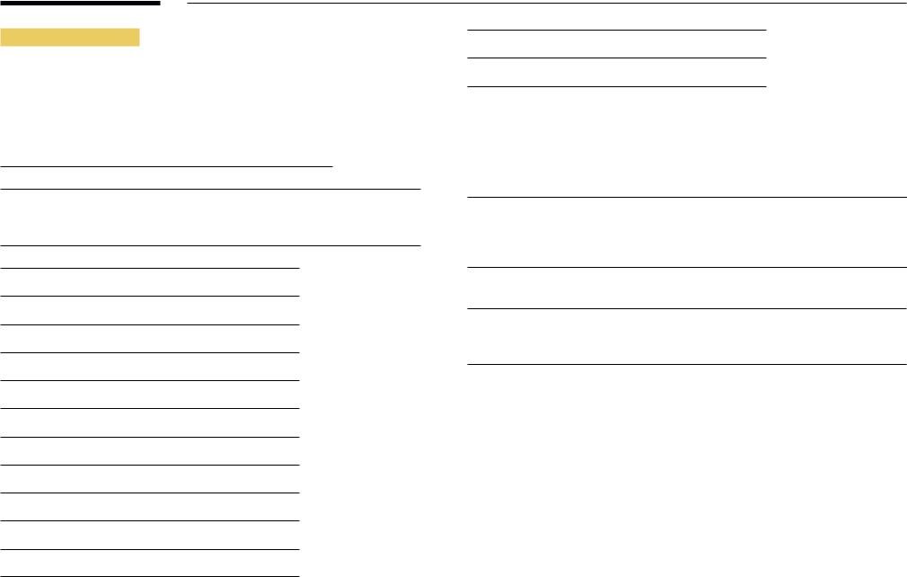
LAN Cable
•• Pin assignment
1 2 3 4 5 6 7 8
Pin No |
Standard Color |
Signal |
|
|
|
1 |
White and orange |
TX+ |
|
|
|
2 |
Orange |
TX- |
|
|
|
3 |
White and green |
RX+ |
|
|
|
4 |
Blue |
NC |
|
|
|
5 |
White and blue |
NC |
|
|
|
6 |
Green |
RX- |
|
|
|
7 |
White and brown |
NC |
|
|
|
8 |
Brown |
NC |
|
|
|
25

•• Connector : RJ45
Direct LAN cable (PC to HUB)
|
|
HUB |
|
P2 |
P1 |
RJ45 |
P1 |
P2 |
|
|
|
|
|
|
|
|
|
|
|
|
|
|
|
|
|
|
|
|
|
|
|
|
|
|
|
|
|
Signal |
P1 |
|
|
P2 |
Signal |
|
|
|
|
|
|
|
|
TX+ |
1 |
< |
--------> |
1 |
TX+ |
|
|
|
|
|
|
|
|
TX- |
2 |
<-------- |
> |
2 |
TX- |
|
|
|
|
|
|
|
|
RX+ |
3 |
<-------- |
> |
3 |
RX+ |
|
|
|
|
|
|
|
|
RX- |
6 |
<-------- |
> |
6 |
RX- |
|
|
|
|
|
|
|
|
Cross LAN cable (PC to PC)
RJ45 |
P1 |
P2 |
|
|
|
|
|
|
|
|
|
|
|
|
|
|
|
|
|
|
|
|
|
|
|
|
Signal |
P1 |
|
|
P2 |
Signal |
|
|
|
|
|
|
TX+ |
1 |
<-------- |
> |
3 |
RX+ |
|
|
|
|
|
|
TX- |
2 |
<-------- |
> |
6 |
RX- |
|
|
|
|
|
|
RX+ |
3 |
<-------- |
> |
1 |
TX+ |
|
|
|
|
|
|
RX- |
6 |
<-------- |
> |
2 |
TX- |
|
|
|
|
|
|
26

Connection
――Ensure you connect each of the adapters to the correct RS232C IN or OUT port on the
product.
•• Connection 1
|
RS232C |
|
RS232C |
|
RS232C |
|
RS232C |
IN |
OUT |
IN |
OUT |
IN |
OUT |
IN |
OUT |
•• Connection 2
RJ45 |
RJ45 |
•• Connection 3
RJ45 |
RS232C |
|
RS232C |
|
RS232C |
|
RS232C |
|
OUT |
IN |
OUT |
IN |
OUT |
IN |
OUT |
27

Control Codes
Viewing control state (Get control command)
Header |
Command |
ID |
Data length |
Checksum |
|
|
|
|
|
0xAA |
Command |
|
0 |
|
|
type |
|
|
|
Controlling (Set control command)
Header |
Command |
ID |
Data length |
Data |
Checksum |
|
|
|
|
|
|
0xAA |
Command |
|
1 |
Value |
|
|
type |
|
|
|
|
Command
No. |
Command type |
Command |
Value range |
|
|
|
|
1 |
Powercontrol |
0x11 |
0~1 |
|
|
|
|
2 |
Volume control |
0x12 |
0~100 |
|
|
|
|
3 |
Input source control |
0x14 |
- |
|
|
|
|
4 |
Screen mode control |
0x18 |
- |
|
|
|
|
5 |
Screen size control |
0x19 |
0~255 |
|
|
|
|
6 |
PIP on/off control |
0x3C |
0~1 |
|
|
|
|
7 |
Auto adjustment control (PC and |
0x3D |
0 |
|
BNC only) |
|
|
|
|
|
|
8 |
Videowall mode control |
0x5C |
0~1 |
No. |
Command type |
Command |
Value range |
|
|
|
|
9 |
Safety Lock |
0x5D |
0~1 |
|
|
|
|
10 |
Video Wall On |
0x84 |
0~1 |
|
|
|
|
11 |
Video Wall User Control |
0x89 |
- |
•• All communicationstake place in hexadecimals. The checksum is calculated byadding
up allvalues exceptthe header. If a checksum adds upto be morethan 2 digits as shown
below(11+FF+01+01=112),thefirst digit is removed.
E.g. PowerOn & ID=0
Header |
Command |
ID |
Data length |
Data 1 |
Checksum |
|
|
|
|
|
|
0xAA |
0x11 |
|
1 |
"Power" |
|
|
|
|
|
|
|
|
|
|
|
|
|
Header |
Command |
ID |
Data length |
Data 1 |
12 |
|
|
|
|
|
|
0xAA |
0x11 |
|
1 |
1 |
|
•• To control all devices connected bya serial cable simultaneouslyirrespective of IDs, set
the ID as "0xFE" andtransmit commands. Commandswill be executed byeach device but
ACKwill not respond.
28

Power control
•• Function
Aproduct can be powered on and off using a PC.
•• Viewing powerstate (Get PowerON / OFF Status)
Header |
Command |
ID |
Data length |
Checksum |
|
|
|
|
|
|
|
|
|
0xAA |
0x11 |
|
0 |
|
|
|
|
|
|
|
|||
•• Setting powerON/Off (Set PowerON / OFF) |
|
|
|
|||
|
|
|
|
|
|
|
Header |
Command |
ID |
Data length |
Data |
|
Checksum |
|
|
|
|
|
|
|
0xAA |
0x11 |
|
1 |
"Power" |
|
|
"Power": Powercodeto be set on a product. 1: PowerON
0: PowerOFF
•• Ack
Header |
Command ID |
Data length |
Ack/Nak |
r-CMD |
Val1 |
Checksum |
|
|
|
|
|
|
|
|
|
0xAA |
0xFF |
3 |
'A' |
0x11 |
"Power" |
|
|
"Power": Powercodeto be set on a product.
•• Nak
Header |
Command |
ID |
Data length |
Ack/Nak |
r-CMD |
Val1 |
Checksum |
|
|
|
|
|
|
|
|
0xAA |
0xFF |
|
3 |
'N' |
0x11 |
"ERR" |
|
"ERR" :Acode showingwhat errorhas occurred.
Volume control
•• |
Function |
|
|
|
|
|
|
|
|
|
|
|
|
|
|
|
|
|
|
Thevolume of a product can be adjusted using a PC. |
|
|
|
|
|
|
|
||||||||||
•• Viewingvolume state (GetVolume Status) |
|
|
|
|
|
|
|
|
|
|||||||||
|
|
|
|
|
|
|
|
|
|
|
|
|
|
|
|
|
||
Header |
Command |
|
|
|
|
ID |
Data length |
Checksum |
|
|
|
|
|
|
||||
|
|
|
|
|
|
|
|
|
|
|
|
|
|
|
|
|
|
|
0xAA |
0x12 |
|
|
|
|
|
|
0 |
|
|
|
|
|
|
|
|
|
|
|
|
|
|
|
|
|
|
|
|
|
|
|
|
|
||||
•• Settingthevolume (SetVolume) |
|
|
|
|
|
|
|
|
|
|
||||||||
|
|
|
|
|
|
|
|
|
|
|
|
|
|
|
||||
Header |
Command |
|
|
|
|
ID |
Data length |
Data |
|
|
Checksum |
|
||||||
|
|
|
|
|
|
|
|
|
|
|
|
|
|
|
|
|
|
|
0xAA |
0x12 |
|
|
|
|
|
|
1 |
|
|
"Volume" |
|
|
|
|
|
|
|
|
|
|
|
|
|
|
|
|
|
|||||||||
"Volume":Volumevalue codeto be set on a product. (0-100) |
|
|
|
|
|
|
||||||||||||
•• |
Ack |
|
|
|
|
|
|
|
|
|
|
|
|
|
|
|
|
|
|
|
|
|
|
|
|
|
|
|
|
|
|||||||
Header |
Command |
|
ID |
|
|
Data length |
Ack/Nak |
r-CMD |
Val1 |
Checksum |
|
|||||||
|
|
|
|
|
|
|
|
|
|
|
|
|
|
|
||||
0xAA |
0xFF |
|
|
3 |
|
|
'A' |
0x12 |
"Volume" |
|
|
|
||||||
|
|
|
|
|
|
|
|
|
|
|||||||||
"Volume":Volumevalue codeto be set on a product. (0-100) |
|
|
|
|
|
|
||||||||||||
•• |
Nak |
|
|
|
|
|
|
|
|
|
|
|
|
|
|
|
|
|
|
|
|
|
|
|
|
|
|
|
|
|
|
||||||
Header |
Command |
|
ID |
|
|
Data length |
Ack/Nak |
r-CMD |
|
Val1 |
Checksum |
|
||||||
|
|
|
|
|
|
|
|
|
|
|
|
|
|
|
||||
0xAA |
0xFF |
|
|
3 |
|
|
'N' |
0x12 |
|
"ERR" |
|
|
|
|||||
"ERR" :Acode showingwhat errorhas occurred.
29
Input source control
•• |
Function |
|
|
|
|
|
|
The input source of a product can be changed using a PC. |
|||||
•• |
Viewing input source state (Get Input Source Status) |
|
||||
|
|
|
|
|
|
|
Header |
Command |
ID |
Data length |
Checksum |
||
|
|
|
|
|
|
|
0xAA |
0x14 |
|
0 |
|
|
|
•• Setting the input source (Set Input Source)
Header |
Command |
ID |
Data length |
Data |
Checksum |
|
|
|
|
|
|
0xAA |
0x14 |
|
1 |
"Input Source" |
|
"Input Source":An input source codeto be set on a product.
0x14 PC
0x18 DVI
0x0C |
Input source |
0x08 Component
0x20 MagicInfo
0x1F DVI_video
0x30 RF(TV)
0x40 DTV
0x21 HDMI1
0x22 HDMI1_PC
0x23 HDMI2
0x24 HDMI2_PC
0x25 DisplayPort
――DVI_video, HDMI1_PC and HDMI2_PC cannot be usedwiththe Set command. Theyonly respond to "Get" commands.
――This model does not support HDMI1, HDMI1_PC, HDMI2 and HDMI2_PC ports.
――MagicInfo is onlyavailablewith modelsthat containthe MagicInfo function. ――RF(TV), DTVare onlyavailablewith modelsthat include a TV.
•• Ack
Header |
Command |
ID |
Data length |
Ack/Nak |
r-CMD |
Val1 |
Checksum |
|
|
|
|
|
|
|
|
0xAA |
0xFF |
|
3 |
'A' |
0x14 |
"Input |
|
|
|
|
|
|
|
Source" |
|
"Input Source":An input source codeto be set on a product.
•• Nak
Header |
Command |
ID |
Data length |
Ack/Nak |
r-CMD |
Val1 |
Checksum |
|
|
|
|
|
|
|
|
0xAA |
0xFF |
|
3 |
'N' |
0x14 |
"ERR" |
|
"ERR" :Acode showingwhat errorhas occurred.
30
 Loading...