


 Loading...
DCS-408 / 408i
Installation
Manual

Publication Information
Samsung Business Communications reserves the right without prior notice to revise information in this publication for any reason.
Samsung Business Communications also reserves the right without prior notice to make changes in design or components of equipment as engineering and manufacturing may warrant.
Disclaimer
Samsung Business Communications is not responsible for errors or problems arising from customers not installing, programming or operating their Samsung systems as described in this manual.
Copyright 2004
Samsung Business Communications
All rights reserved. No part of this manual may be reproduced in any form or by any means
– graphic, electronic or mechanical, including recording, taping, photocopy or information retrieval system – without express written permission of the publisher of this material.
Part No.: 17260 |
Version 2.1 |

EU Declaration of Conformity (RTTE)
Samsung Electronics Co., Ltd.
259 Gongdan-Dong, Gumi-City Kyungbuk, Korea, 730-030
(factory name, address)
declare under our sole responsibility that the product
Digital Keyphone System "DCS-408"
to which this declaration relates is in conformity with
RTTE Directive 1999/5/EC ( Annex II )
Low Voltage Directive 73/23/EEC:93/68/EEC
EMC Directive 89/336/EEC:92/31/EEC
By application of the following standards
EN55022 : 1998 Inc A1: 2000* , EN55024 : 1998 +A1:2001
EN61000-3-2:1995 Inc. A1/A2:1998
EN61000-3-3:1995, EN61000-4-2:1995 Inc. A1:1998, EN61000-4-3:1996 Inc. A1:1998
EN61000-4-4:1995, EN61000-4-5:1995, EN61000-4-6:1996, EN61000-4-8:1993
EN61000-4-11:1994, AS/NZS3548:1995
EN60950 ; 1992+A1+A2+A3+A4+A11
(Manufacturer)
Samsung Electronics Co., Ltd
259, Gongdan-Dong, Gumi-City
Kyungbuk, Korea, 730-030
2000-12-08 |
TE Jang |
Tae-eok Jang / General Manager |
................................................. |
|
................................................................................. |
(place and date of issue) |
(name and signature of authorized person) |
|
(Representative in the EU) |
|
|
Samsung Electronics Euro QA Lab. |
|
|
Blackbushe Business Park |
|
|
Saxony Way, Yateley, Hampshire |
|
|
GU46 6GG, UK |
|
|
2000-12-08 |
IS Lee |
In-Seop Lee / Manager |
................................................. |
|
............................................................................... |
(place and date of issue) |
(name and signature of authorized person) |
EU Declaration of Conformity (RTTE)
Samsung Electronics Co., Ltd.
259 Gongdan-Dong, Gumi-City Kyungbuk, Korea, 730-030
(factory name, address)
declare under our sole responsibility that the product
Digital Keyphone System "DCS-408i"
to which this declaration relates is in conformity with
RTTE Directive 1999/5/EC ( Annex II )
Low Voltage Directive 73/23/EEC:93/68/EEC
EMC Directive 89/336/EEC:92/31/EEC
By application of the following standards
EN55022 : 1998 Inc A1: 2000* , EN55024 : 1998 +A1:2001
EN61000-3-2:1995 Inc. A1/A2:1998
EN61000-3-3:1995, EN61000-4-2:1995 Inc. A1:1998, EN61000-4-3:1996 Inc. A1:1998
EN61000-4-4:1995, EN61000-4-5:1995, EN61000-4-6:1996, EN61000-4-8:1993
EN61000-4-11:1994, AS/NZS3548:1995
EN60950 ; 1992+A1+A2+A3+A4+A11
(Manufacturer)
Samsung Electronics Co., Ltd
259, Gongdan-Dong, Gumi-City
Kyungbuk, Korea, 730-030
2001-06-07 |
TE Jang |
Tae-eok Jang / General Manager |
................................................. |
|
................................................................................. |
(place and date of issue) |
(name and signature of authorized person) |
|
(Representative in the EU) |
|
|
Samsung Electronics Euro QA Lab. |
|
|
Blackbushe Business Park |
|
|
Saxony Way, Yateley, Hampshire |
|
|
GU46 6GG, UK |
|
|
2001-06-11 |
IS Lee |
In-Seop Lee / Manager |
................................................. |
|
............................................................................... |
(place and date of issue) |
(name and signature of authorized person) |

Intended Use
This telephone system is intended to provide the user with voice communication between the system extensions and connection to the public switched telephone network by digital or analogue links.
The telephone system may be provided with the ability to communicate with local computer networks to provide CTI functions and features. In this case, it is capable of passing information to the computer network via a specified link.
The system is powered by mains voltage and can optionally be powered by batteries. Details of all connections and power arrangements are provided in the instructions for use. It should not be used in any other way.

Samsung |
|
DCS-408 & 408i Keyphone System |
Installation Manual |
Chapter 1 Keyphone System Overview................................. |
1 |
System Features ................................................................................................... |
1 |
System Overview .................................................................................................. |
1 |
Product Safety Precautions .................................................................................. |
4 |
Chapter 2 Keyphone System Installation.............................. |
5 |
Environment Requirements ................................................................................... |
5 |
Precautions for Installation..................................................................................... |
5 |
Unpacking the System........................................................................................... |
6 |
Procedure for Removing Covers............................................................................ |
7 |
Installation Procedure ........................................................................................... |
9 |
Grounding ...................................................................................................................... |
9 |
Fixing the System on the Wall (Optional) ..................................................................... |
11 |
Testing Initial System Operation .................................................................................. |
12 |
Installing the Battery .................................................................................................... |
13 |
Installing Cables .......................................................................................................... |
15 |
Connecting Trunks ...................................................................................................... |
18 |
Connecting Telephones ............................................................................................... |
19 |
System Options ................................................................................................. |
20 |
Trunk Line and Station Line Assignment ............................................................ |
21 |
Digital Keyset Programming ............................................................................... |
22 |
Replacing System ROMs .................................................................................... |
22 |
Chapter 3 Connecting Additional Equipment .................... |
24 |
Music-On-Hold/Background Music ..................................................................... |
24 |
External Paging ................................................................................................. |
25 |
Common Bell ...................................................................................................... |
26 |
Station Message Detail Recording (SMDR) ........................................................ |
27 |
PC and Remote Programming ............................................................................ |
27 |
Computer Telephony (CTM-CTI) ......................................................................... |
28 |
Voice Mail/Auto Attendant ................................................................................... |
29 |
Doorphone and Door Lock Release .................................................................... |
29 |
Appendix A System Specifications .................................... |
31 |
Appendix B Troubleshooting .............................................. |
32 |
Appendix C Glossary ........................................................... |
33 |
– i –
Samsung |
|
DCS-408 & 408i Keyphone System |
Installation Manual |
The DCS-408/DCS-408i digital keyphone system is designed to be suitable for a small office. Both the DCS-408 and DCS-408i system comprise a baseboard to which eight (8) station lines (four circuits for digital keysets and four lines for analogue telephones) can be connected.
While the DCS-408 system accommodates four analogue trunk lines, the DCS-408i system accommodates two BRI lines (four channels). Moreover, the BRI2 line (two channels) of the DCS-408i system can be substituted for ISDN station lines.
System Features
ySimple and slim design.
ySupports the Plug & Play function and is easy to install.
yDisplays the call list.
ySupports a doorphone interface module (DPIM) connection allowing use of a doorphone.
yAccommodates eight station lines.
yDCS-408 accommodates four analogue trunk lines and DCS-408i accommodates four digital trunk channels. The BRI2 line (two channels) of the DCS-408i system can be substituted for ISDN station lines.
NOTE: The DCS-408/DCS-408i digital keyphone system does not support add-on-modules (AOMs) or KDB-DLI and KDB-SLI keysets.
System Overview
General Details
Item |
Details |
|
|
CPU |
MC68EC000 (16MHz) 16Bit Mode |
|
ROM (DCS-408): 1Mbyte (2 x 27C4001) |
Memory |
ROM (DCS-408i): 2Mbyte (4 x 27C4001) |
|
RAM: 256 kbytes (2x681000) |
Switch Structure |
256 x 256 Time Slot |
SIO port |
RS-232C (SIO) |
|
|
– 1 –
Samsung |
|
DCS-408 & 408i Keyphone System |
Installation Manual |
System Dimensions
|
Item |
|
Height |
|
Width |
|
Depth |
|
Weight |
|
|
|
(mm) |
|
(mm) |
|
(mm) |
|
(kg) |
|
|
|
|
|
|
|
|
|
||||
|
DCS-408/DCS-408i |
190 |
350 |
60 |
2.0 |
|
||||
|
DPIM |
29 |
90 |
120 |
0.2 |
|
||||
|
|
|
|
|
|
|
|
|
|
|
System Structure
System Capacity
Trunk
Station
Music-on-hold/ Background music channel
General-purpose dry contact
SIO port
External page
DCS-408: 4 analogue trunk lines
DCS-408i: 2 BRI lines (4 channels)
(BRI2 line (2 channels) can be substituted for ISDN station lines)
8 lines (4 lines for digital keysets and 4 lines for analogue telephones)
1 (internal or external)
1
1
1
CAUTION: The station lines have a fixed configuration of eight lines: 4 lines for digital keysets and 4 lines for analogue telephones. It is not possible to modify this configuration.
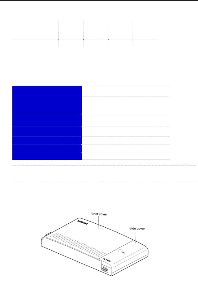
Front View of System
– 2 –
Samsung |
|
DCS-408 & 408i Keyphone System |
Installation Manual |
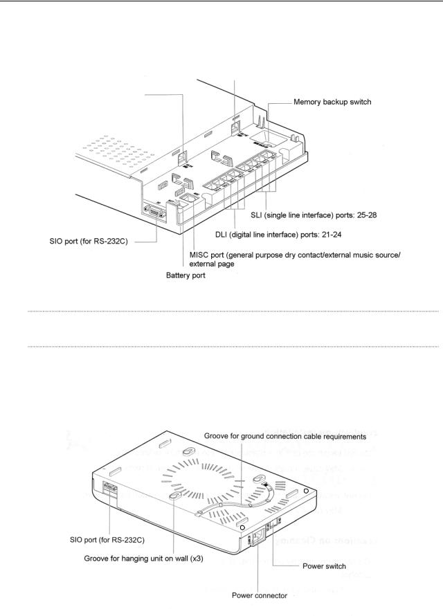
System Ports (After Removing Side Cover)
CO1.2/BRI1 port
CO3.4/BRI2 port
NOTE: Only the DCS-408i system supports the BRI feature.
Rear View of System
– 3 –

Samsung |
|
DCS-408 & 408i Keyphone System |
Installation Manual |
Product Safety Precautions
Precautions on Installation
Do not install the unit in a location subject to moisture or wetness.
► May cause a malfunction or shorten the lifespan of components.
Do not install the unit in a location near a heat source such as a heater.
► May cause a fire.
Precautions on Use
Do not attempt repair or modification yourself.
► Contact a service centre if repair is required.
If abnormal sounds, smells or smoke come from a telephone, immediately unplug the telephone line and contact a service centre.
► If the unit is left in this state, a fire may result.
Precautions on Cleaning
Do not spray cleaning fluids directly on the unit, and do not clean the unit with benzene, thinner or alcohol.
► May cause a fire or an electric shock.
– 4 –
Samsung |
|
DCS-408 & 408i Keyphone System |
Installation Manual |
This chapter describes the installation procedures for the DCS-408/408i digital keyphone system, including precautions for your safety. Read this chapter carefully before installing the system.
Environmental Requirements
y Temperature: |
0°–40°C (32°–104°F) |
y Relative Humidity: |
Maximum 90% (non-condensing) |
y Power Specifications: |
Power supply of 60 or more watts |
|
220VAC–240VAC, 1.6A |
y Regular Frequency: |
50Hz |
Keep the unit away from static electricity and electrical noise
If there is a possibility of static electricity or electrical “noise” occurring where the keyphone system is installed (due to carpets, electrical machinery, etc), measures for preventing this should be put in place.
Install the unit where it is not exposed to harmful conditions
Be careful not to expose the system to direct sunlight, corrosive vapour, dust, regular vibration or high levels of magnetic fields generated by motors or copying machines.
Precautions for Installation
Selecting Location
Select a location having sufficient space and levels of brightness to facilitate installation.
Preventing Static Electricity
The unit should not be installed in a room with carpets. To ensure safety, discharge any static electricity by touching the metal portion of a grounded object or the ground connection on the system before installing or repairing the system.
In addition, for protection and reliable operation of the system, standard grounding conditions should be met.
Cable Requirements
Select a location which minimises the length of system cables, and ensure that all cables to and from the system are not damaged. In addition, take care to protect all cables from electromagnetic interference; for instance, by keeping them at a safe distance from cables for other equipment.
– 5 –

Samsung |
|
DCS-408 & 408i Keyphone System |
Installation Manual |
Refer to the cable requirements shown in the following table.
|
Equipment |
|
Cables |
|
AWG |
|
Max |
|
Max |
|
|
|
|
|
Feet |
|
Metres |
|
|||
|
|
|
|
|
|
|
|
|
||
|
Digital keyset |
|
1 pr. twisted |
|
24 (0.5mm) |
1300 |
400 |
|
||
|
Analogue telephone |
|
1 pr. twisted |
|
24 (0.5mm) |
3000 |
1000 |
|
||
|
Doorphone |
|
2 pr. twisted |
|
24 (0.5mm) |
330 |
100 |
|
||
|
DPIM |
|
1 pr. twisted |
|
24 (0.5mm) |
1000 |
300 |
|
||
|
|
|
|
|
|
|
|
|
|
|
Line Conditions
When using AWG 24 (0.5 mm) cables, the maximum length of a cable for analogue telephones, digital keysets, doorphones and doorphone interface modules (DPIM) is as shown in the table above.
Be careful not to fold cables, make contact with other equipment or otherwise damage cables during installation. Do not run cables outside of the building.
Checking Power
If the keyphone system shares AC power with other machines, problems from noise, malfunctioning due to voltage drops, or fire may result. Moreover, interruption of power at night may cause malfunctioning and breakdown of the battery.
CAUTION: Always use a dedicated, stable AC power supply for the system
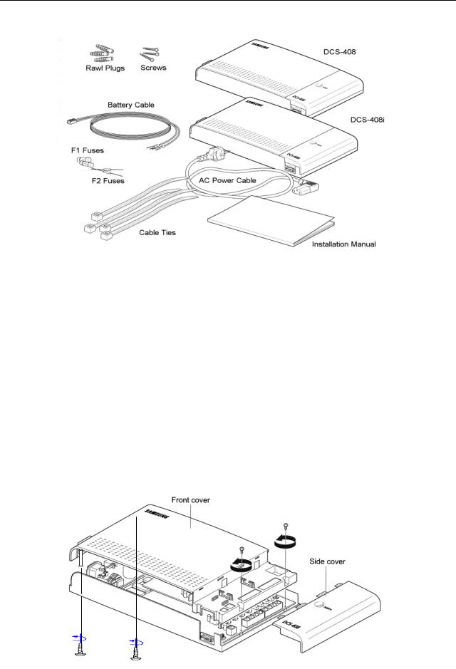
Unpacking the System
Unpack your DCS-408/408i digital keyphone system and check that there is no damage to any item. If you discover any damage, contact your dealer before attempting installation. Also check that you have received the following items (as well as this manual!).
yDCS-408/408i Digital Keyphone System main unit
yThree screws and three rawl plugs for hanging the unit on the wall
yCable for battery connection
yTwo AC power fuses (F1) - 250V, 2A
yTwo battery fuses (F2) - 125V, 3A
yAC power cable
yFour cable ties
– 6 –
Samsung |
|
DCS-408 & 408i Keyphone System |
Installation Manual |
Procedure for Removing the Covers
The system cover comprises a front cover and a side cover. Refer to the diagram below to remove the covers.
Removing the Side Cover
Viewed from the top, the small cover on the right-hand side is the side cover. A round indent in the side cover is marked PUSH. To remove the side cover, push it to the right while gently pressing the indent.
Removing the Front Cover
After removing the side cover, loosen the four screws holding the front cover, as shown. Two are located under the side cover and two are on the base of the unit. After removing the screws, hold the sides of the front cover and pull gently to remove it.
– 7 –
Loading...