


SAMSUNG CW21A83NS8XEC, WS28W8VDESXXEC, CW28C93WS8XXEG, WS28W73WS8XXEG, WS32W74WS8XXEG Service Manual

COLOR TELEVISION RECEIVER
Chassis : KS3A(P) (REV. 2)
Model : CW21A83NS8XEC
WS28W8VDESXXEC
CW28C93WS8XXEG
WS28W73WS8XXEG
WS32W74WS8XXEG
COLOR TELEVISION RECEIVER |
|
CONTENTS |
1. Precautions
2. Reference Information
3. Specifications
4. Alignment and Adjustments
5. Troubleshooting
6. Exploded Views and Parts List
7. Electrical Parts List
8. Block Diagrams
9. Wiring Diagram
10. Schematic Diagrams

ELECTRONICS
©Samsung Electronics Co., Ltd. SEP. 2001 Printed in Korea
3KS3A-SEH-0917

Reference Information
2. Reference Information
2-1 Tables of Abbreviations and Acronyms
Table 2-1 Abbreviations
A |
Ampere |
MV |
Megavolt |
Ah |
Ampere-hour |
MW |
Megawatt |
Å |
Angstrom |
MΩ |
Megohm |
dB |
Decibel |
m |
Meter |
dBm |
Decibel Referenced to One |
µA |
Microampere |
°C |
Milliwatt |
µF |
Microfarad |
Degree Celsius |
µH |
Microhenry |
|
°F |
Degree Fahrenheit |
µm |
Micrometer |
°K |
degree Kelvin |
µs |
Microsecond |
F |
Farad |
µW |
Microwatt |
G |
Gauss |
mA |
Milliampere |
GHz |
Gigahertz |
mg |
Milligram |
g |
Gram |
mH |
Millihenry |
H |
Henry |
mI |
Milliliter |
Hz |
Hertz |
mm |
Millimeter |
h |
Hour |
ms |
Millisecond |
ips |
Inches Per Second |
mV |
Millivolt |
kWh |
Kilowatt-hour |
nF |
Nanofarad |
kg |
Kilogram |
Ω |
Ohm |
kHz |
Kilohertz |
pF |
Picofarad |
kΩ |
Kilohm |
Ib |
Pound |
km |
Kilometer |
rpm |
Revolutions Per Minute |
km/h |
Kilometer Per Hour |
rps |
Revolutions Per Second |
kV |
Kilovolt |
s |
Second (Time) |
kVA |
Kilovolt-ampere |
V |
Volt |
kW |
Kilowatt |
VA |
Volt-ampere |
I |
Liter |
W |
Watt |
MHz |
Megahertz |
Wh |
Watt-hour |
Samsung Electronics |
2-1 |

Reference Information
Table 2-2 Table of Acronyms
ABL |
Automatic Brightness Limiter |
I/O |
Input/output |
AC |
Alternating Current |
L |
Left |
ACC |
Automatic Chroma Control |
L |
Low |
AF |
Audio Frequency |
LED |
Light Emitting Diode |
AFC |
Automatic Frequency Control |
LF |
Low Frequency |
AFT |
Automatic Fine Tuning |
MOSFET |
Metal-Oxide-Semiconductor-Field-Effect-Tr |
AGC |
Automatic Gain Control |
MTS |
Multi-channel Television Sound |
AM |
Amplitude Modulation |
NAB |
National Association of Broadcasters |
ANSI |
American National Standards Institute |
NEC |
National Electric Code |
APC |
Automatic Phase Control |
NTSC |
National Television Systems Committee |
APC |
Automatic Picture Control |
OSD |
On Screen Display |
A/V |
Audio-Video |
PCB |
Printed Circuit Board |
AVC |
Automatic Volume Control |
PLL |
Phase-Locked Loop |
BAL |
Balance |
PWM |
Pulse Width Modulation |
BPF |
Bandpass Filter |
QIF |
Quadrature Intermediate Frequency |
B-Y |
Blue-Y |
R |
Right |
CATV |
Community Antenna Television (Cable TV) |
RC |
Resistor & Capacitor |
CB |
Citizens Band |
RF |
Radio Frequency |
CCD |
Charge Coupled Device |
R-Y |
Red-Y |
CCTV |
Closed Circuit Television |
SAP |
Second Audio Program |
Ch |
Channel |
SAW |
Surface Acoustic Wave(Filter) |
CRT |
Cathode Ray Tube |
SIF |
Sound Intermediate Frequency |
CW |
Continuous Wave |
SMPS |
Switching Mode Power Supply |
DC |
Direct Current |
S/N |
Signal/Noise |
DVM |
Digital Volt Meter |
SW |
Switch |
EIA |
Electronics Industries Association |
TP |
Test Point |
ESD |
Electrostatic Discharge |
TTL |
Transistor Transistor Logic |
ESD |
Electrostatically Sensitive Device |
TV |
Television |
FBP |
Feedback Pulse |
UHF |
Ultra High Frequency |
FBT |
Flyback Transformer |
UL |
Underwriters Laboratories |
FF |
Flip-Flop |
UV |
Ultraviolet |
FM |
Frequency Modulation |
VCD |
Variable-Capacitance Diode |
FS |
Fail Safe |
VCO |
Voltage Controlled Oscillator |
GND |
Ground |
VCXO |
Voltage Controlled Crystal Oscillator |
G-Y |
Green-Y |
VHF |
Very High Frequency |
H |
High |
VIF |
Video Intermediate Frequency |
HF |
High-Frequency |
VR |
Variable Resistor |
HI-FI |
High Fidelity |
VTR |
Video Tape Recorder |
IC |
Inductance-Capacitance |
VTVM |
Vacuum Tube Voltmeter |
IC |
Integrated Circuit |
TR |
Transistor |
IF |
Intermediate Frequency |
|
|
|
|
|
|
2-2 |
Samsung Electronics |

Reference Information
2-2 IC Line Up
Table 2 - 3 IC Line - Up
|
|
|
|
|
|
|
|
|
|
|
NO |
|
|
BOARD |
|
LOC. NO |
SPEC |
DESCRIPTION |
REMARK |
|
|
|
|
|
|
|
|
|
|
|
|
|
|
|
|
IC201S |
VDP3112B |
Video Processor |
Refer to Table 2-3-1 |
|
|
|
|
|
|
|
|
|
|
|
|
|
|
|
|
IC601 |
MSP3411G |
Multistandard Sound Processor |
Refer to Table 2-3-2 |
|
|
|
|
|
|
|
|
|
|
|
|
|
|
|
|
IC901 |
SDA555X |
MICOM, TTX(MTP) |
|
|
|
|
|
|
|
|
|
|
|
|
|
|
|
|
|
IC902 |
KS24L161 |
EEPROM |
|
|
|
|
|
|
|
|
|
|
|
|
|
|
|
|
|
IC602 |
TDA7297 |
Audio AMP |
Refer to Table 2-3-3 |
|
|
|
|
|
|
|
|
|
|
|
|
|
|
|
|
HIC201 |
|
|
VM Option |
|
|
|
|
|
|
HIC202 |
DRGB001 |
RGB Drive AMP Hybrid IC |
|
|
|
|
|
|
|
|
|
||
|
|
|
|
|
|
HIC203 |
|
|
|
|
|
|
|
|
|
|
|
|
|
|
|
|
|
|
|
HIC204 |
|
|
|
|
|
|
|
|
|
|
|
|
|
|
|
|
|
|
|
HIC401 |
DDRI001 |
100Hz Horizontal Pulse AMP |
Option |
|
|
|
|
|
|
|
|
|
|
|
|
|
|
|
|
IC301 |
LA7845 |
Vertical IC |
|
|
|
|
|
|
|
|
|
|
|
|
|
|
|
|
|
Q402 |
KSC2073-H2 |
|
|
|
|
|
|
|
|
|
|
Horizontal Drive IC |
|
|
|
|
|
|
|
Q401 |
KSD5703 |
HC401 |
|
|
|
|
|
|
|
|
|
|
|
|
|
|
|
|
|
D414 |
FMP-3FU |
|
|
|
|
|
|
|
|
|
|
||
|
|
|
|
|
|
|
|
|
|
|
|
|
|
|
|
IC401 |
KA393 |
E/W Drive IC |
|
|
1 |
|
|
MAIN |
|
|
|
|
|
|
|
|
|
Q404 |
IRF620 |
|
|||
|
|
|
|
|
|
||||
|
|
|
|
|
|
|
|
||
|
|
|
|
|
|
|
|
|
|
|
|
|
|
|
|
IC801S |
3S1265R |
SPS Controllor |
|
|
|
|
|
|
|
|
|
|
|
|
|
|
|
|
|
D801S |
RBV606 |
Bridge Diode |
|
|
|
|
|
|
|
|
|
|
|
|
|
|
|
|
|
PC801S |
PC123Y |
Photo Coupler |
|
|
|
|
|
|
|
|
|
|
|
|
|
|
|
|
|
IC802 |
KA78R05 |
5V Controlled Regulator |
|
|
|
|
|
|
|
D805 |
|
|
|
|
|
|
|
|
|
|
FML-G12S |
Rectifier Diode |
HC801 |
|
|
|
|
|
|
D806 |
|||
|
|
|
|
|
|
|
|
|
|
|
|
|
|
|
|
D807 |
|
|
|
|
|
|
|
|
|
|
|
|
|
|
|
|
|
|
|
D802 |
FMG-G2CS |
|
|
|
|
|
|
|
|
|
|
|
|
|
|
|
|
|
|
IC201 |
KA78RM33 |
3.3V Regulator |
VDPY |
|
|
|
|
|
|
|
|
|
|
|
|
|
|
|
|
IC804 |
KA7806 |
6V Regulator |
|
|
|
|
|
|
|
|
|
|
|
|
|
|
|
|
|
IC803 |
KA78R08 |
8V Controlled Regulator |
|
|
|
|
|
|
|
|
|
|
|
|
|
|
|
|
|
IC903 |
KA78RM33 |
3.3V Regulator |
|
|
|
|
|
|
|
|
|
|
|
|
|
|
|
|
|
IC904 |
KIA7025AP |
MICOM Reset IC |
|
|
|
|
|
|
|
|
|
|
|
|
|
|
|
|
|
Q909 |
2N7000 |
IIC Level Shifter |
|
|
|
|
|
|
|
|
|
||
|
|
|
|
|
|
Q910 |
|
||
|
|
|
|
|
|
|
|
|
|
|
|
|
|
|
|
|
|
|
|
|
|
|
|
|
|
TU01S |
TCLS3101PD09A9(S) |
Main Tuner with IF Block |
Refer to Table 2-3-4 |
|
|
|
|
|
|
TU02S |
TCPN3081PD09A(S) |
Sub Tuner with IF Block |
Refer to Table 2-3-5 |
|
|
|
|
|
|
||||
|
|
|
|
|
|
|
|
|
|
Samsung Electronics |
2-3 |

Reference Information
Table 2 - 3 IC Line - Up
NO |
BOARD |
LOC. NO |
SPEC |
DESCRIPTION |
REMARK |
|
1 |
MAIN |
T801S |
AA26-00046A |
Trans Switching |
Refer to Table 2-3-6 |
|
|
|
|
|
|||
T444S |
FUJ-29B001 |
Trans FBT |
Refer to Table 2-3-7 |
|||
|
|
|||||
|
|
|
|
|
|
|
|
|
IC501 |
|
|
|
|
|
|
|
TDA6111Q |
Video Output AMP R.G.B Drive |
|
|
|
|
IC502 |
|
|||
|
|
|
|
|
|
|
2 |
CRT |
IC503 |
|
|
|
|
|
|
|
|
|||
QF04 |
2SC2344 |
Push-Pull (VM) |
|
|||
|
|
|
||||
|
|
|
|
|
||
|
|
QF05 |
2SA1011 |
Option |
||
|
|
|
||||
|
|
|
|
|
||
|
|
QG02 |
KSA940 |
TR-Power (TILT) |
||
|
|
|
||||
|
|
|
|
|
||
|
|
QG03 |
KSD2073-H2 |
|
||
|
|
|
|
|||
|
|
|
|
|
|
|
|
|
ICG01 |
KA4558 |
OP-AMP (TILT) |
|
|
|
|
|
|
|
|
|
3 |
DOUBLE |
ICH01 |
KA4558 |
OP-AMP |
Option |
|
|
|
|
|
|||
|
FOCUS |
QH01 |
2SC4636RB |
TR-Power |
Option |
|
|
|
|
|
|
|
|
4 |
V-S/W |
ICS01 |
TEA6425 |
Video Switching IC with Adder Output |
Option |
|
|
|
|
|
|
|
|
5 |
PIP |
ICP01 |
SDA9489X |
High-end Picture-In Picture IC |
|
|
|
|
|
|
|||
ICP02 |
EZ1086CM |
3.3V Regulator |
|
|||
|
|
|
||||
|
|
|
|
|
|
2-4 |
Samsung Electronics |

Reference Information
Table 2-3-1 VIDEO IC (IC201S)
SPEC |
FUNCTION |
REMARK |
|
|
|
VDP3108B |
50Hz Basic |
|
|
|
|
VDP3112B |
50Hz, 2H Comb Filtr |
|
|
|
|
VDP3120B |
50Hz, 2H Comb Filter, Horizontal Scaler |
|
|
|
|
VDP3130Y |
50Hz, 2H Comb Filter, DVD Input |
|
|
|
|
VDP3140D |
100Hz |
|
|
|
|
Table 2-3-2 SOUND IC (IC601) |
|
|
|
|
|
SPEC |
FUNCTION |
REMARK |
|
|
|
MSP3400D |
Multistandard, A2 Stereo |
|
|
|
|
MSP3410D |
Multistandard, A2 Stereo, Nicam |
|
|
|
|
MSP3411G |
Multistandard, A2 Stereo, Nicam, Vitual Dolby |
|
|
|
|
Table 2-3-3 SOUND AMP (IC602) |
|
|
|
|
|
SPEC |
FUNCTION |
REMARK |
|
|
|
TDA7297 |
15W x 2CH, 10W x 2CH |
|
|
|
|
Table 2-3-4 1’st TUNER (TU01S) |
|
|
|
|
|
SPEC |
FUNCTION |
REMARK |
|
|
|
TCLS3101PD09A(S) |
CS with LNA Function |
Main |
|
|
|
TCPS3001PD09D(S) |
CS |
|
|
|
|
TCPS3001PD09E(S) |
CS |
India |
|
|
|
Note TCPS3001PD09A(S) is out-of-date, TCPS3001PD09D(S) which is up-to-date has the same function.
Table 2-3-5 2’nd TUNER (TU02S)
SPEC |
FUNCTION |
REMARK |
|
|
|
TCPS3000PC09B(S) |
CS |
Sub |
|
|
|
Samsung Electronics |
2-5 |

Reference Information
Table 2-3-6 TRANS
SPEC |
FUNCTION |
REMARK |
|
|
|
FUJ-29B001 |
29” |
|
|
|
|
FUH-29A001B |
21” |
|
|
|
|
Table 2-3-7 TRANS FLYBACK (FBT) |
|
|
|
|
|
SPEC |
FUNCTION |
REMARK |
|
|
|
AA26-00046A |
29” |
|
|
|
|
AA26-00044C |
21” |
|
|
|
|
2-6 |
Samsung Electronics |

Alignment and Adjustments
4. Alignment and Adjustments
4-1 General Alignment Instructions
1.Usually, a color TV-VCR needs only slight touch-up adjustment upon installation. Check the basic characteristics such as height, horizontal and vertical sync and focus.
2.Observe the picture for good black and white details. There should be objectionable color shading; if color shading is present, demagnetize, perform purity and convergence adjustments described below.
3.Use the specified test equipment or its equivalent.
4.Correct impedance matching is essential.
5.Avoid overload. Excessive signal from a sweep generator might overload the front-end of the TV. When inserting signal markers, do not allow the marker generator to distort test results.
6.Connect the TV only to an AC power source with voltage and frequency as specified on the backcover nameplate.
7.Do not attempt to connect or disconnect any wires while the TV is turned on. Make sure that the power cord is disconnected before replacing any parts.
8.To protect against shock hazard, use an isolation transformer.
4-2 Automatic Degaussing
A degaussing coil is mounted around the picture tube, so that external degaussing after moving the TV should be unnecessary. But the receiver must be properly degaussed upon installation.
The degaussing coil operates for about 1 second after the power is switched ON. If the set is moved or turned in a different direction, the power should be OFF for at least 10 minutes.
If the chassis or parts of the cabinet become magnetized, poor color purity will result. If this happens, use an external degaussing coil. Slowly move the degaussing coil around the faceplate of the picture tube and the sides and front of the receiver. Slowly withdraw the coil to a distance of about 6 feet before turning power OFF.
If color shading persists, perform the following Color purity and Convergence adjustments.
4-3 High voltage Check
CAUTION : There is no high voltage adjustment on this chassis. The B+ power supply should be +135 volts (with full colorbar input and normal picture level).
1.Connect a digital voltmeter to the second anode of the picture tube.
2.Turn on the TV. Set the Brightness and Contrast controls to minimum (zero beam current).
3.Adjust the Brightness and contrast controls to both extremes. Ensure that the high voltage does not exceed 32 KV under any conditions.
Samsung Electronics |
4-1 |
Alignment and Adjustments
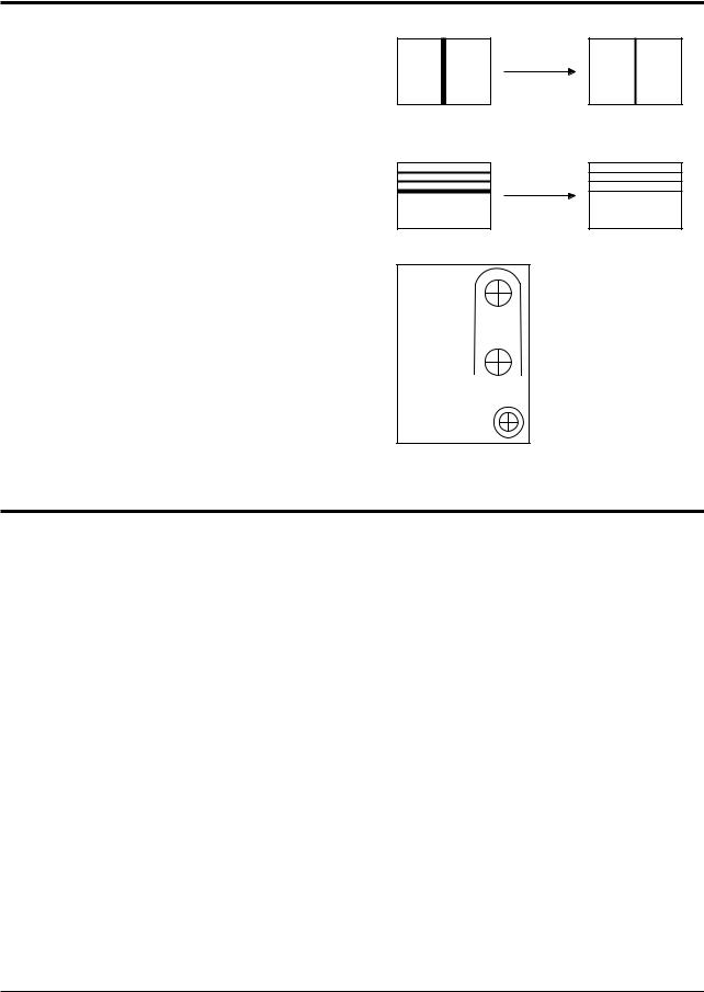
4-4 Dynamic Focus Adjustment
1.A dynamic focus adjustment should be done after replacing the CRT PCB, FBT or CRT.
2. Input a crosshatch pattern. |
|
3.Enter “ STANDARD “ in video mode.
4.Turn the Dynamic focus VR fully clockwise (maximum).( )
5.Turn the Static focus VR fully counterclockwise (maximum).( )
6.Slowly turn the static focus VR counterclockwise. Adjust until the vertical line in the middle of the screen has maximum clarity.( )
7.Slowly turn the dynamic focus VR (clockwise) and adjust the 3rd horizontal line for maximum clarity.( )
 STATIC FOCUS VR
H
 DYNAMIC FOCUS VR
 V
V
8. Repeat 4-7, if necessary. |
SCREEN |
<FBT FOCUS PACK>
4-5 SCREEN Adjustment
1.Input Toshiba Pattern
2.Enter “Service Mode”.(Refer to “Service Mode”)
3.Select “G2-Adjust”.
4.Set the values as below.
|
29 Inch |
|
21 Inch |
|
|
|
|
IBRM |
= 220 |
IBRM |
= 220 |
WDRV = 35 |
WDRV = 35 |
||
CDL |
= 220 |
CDL |
= 165 |
COLR G B = 150 150 150 |
COL |
= 70 |
|
|
|
|
|
4-2 |
Samsung Electronics |
Alignment and Adjustments
5.Turn the SCREEN VR until “MRCR G B” and “MRWDG” are green and those value are about 100. (The incorrect SCREEN Voltage may result that “MRCR G B” and “MRWDG” should be red)
Note 1. When you do not have Toshiba Pattern, follow this method.
1.Set the TV on the condition that AV mode no signal(black)
2.Enter the “Menu” and set the mode to blue screen off.
3.Enter the “Service Mode”.
4.Select “ G2-Adjust”.
5.Set the values as below.
IBRM |
= 220 |
WDRV = 35 |
|
CDL |
= 220 |
COLR G B = 150 150 150
6.Turn the SCREEN VR until the value of “ MRCR G B” is about 120. Do not mind that the “OSD” Color is red.
After completing G2-Adjust, follow this procedure.
Enter the “Video Adjust 1”.
Choose any item in menu. (ex. Select “Red Cutoff”)
Change the value of item you select, and recover the value.
For example, when the value of “Red Cutoff” is 127, change the value to 128 and restore the value to 127.
If you do not follow this procedure, the picture may be abnormal.
For example, when the TV set is on, the picture becames brighter gradually.
Samsung Electronics |
4-3 |

Alignment and Adjustments
4-6 E2PROM (IC902) Replacement
1.When IC902 is replaced, all adjustment data revert to the initial values. So, all adjustment values when servicing should be readjusted.
2.After IC902 is replaced, connect the AC power supply cord.
3.Turn the power switch ON.
4.In stand-by, warm up the TV for at least 10 seconds.
5.Power on the TV.
4-7 White Balance Adjustment
■Equipment : Color-Analyzer (CA-100)
■Input Signal : Pattern signal (Toshiba pattern)
1.Select STANDARD from the menu.
2.Input an 100% White pattern.
3.Enter the “Service Mode”. (Refer to “4-8 Service Mode”)
4.Warm up the TV set at least for 30 minutes.
5.Input a Toshiba pattern signal.
6.Enter the “Video Adjust1”.
-Adjust “Sub Contrast” so that Y (luminance) becomes 40 ft ± 3.
-Use “Red Drive” and “ Blue Drive” to adjust High-Light (x : 290, y : 300)
-Adjust “Sub Bright” so that Y (luminance) becomes 1.3ft ± 0.3.
-Use “Red Cutoff” and “Blue Cutoff” to adjust Low-Light (x : 290, y : 300).
7.Adjust CA-100 so that the final adjustment value can be fixed.
8.Use the Channel Up/Down (▲/▼) buttons to move the cursor on the adjustment modes.
9.Use the Volume +/- buttons to change the adjustment value.
4-4 |
Samsung Electronics |

Alignment and Adjustments
4-8 Factory Adjustment
4-8-1 Service Mode
1.To enter the “Service Mode”, Press the remote-control keys in this sequence : - If you do not have Factory remote-control
|
PICTURE OFF |
|
|
|
|
|
DISPLAY ( |
) |
|
|
|
|
|
MENU |
|
|
|
MUTE |
|
|
PICTURE ON |
||
|
|
|
|
|
|
||||||||||||||||||
|
|
|
|
|
|
|
|
|
|
|
|
|
|
|
|
|
|
|
|
|
|||
- If you have Factory remote-control |
|
|
|
|
|
|
|
|
|
|
|
|
|||||||||||
|
|
|
|
|
|
|
|
|
|
|
|
|
|
|
|
|
|
|
|
|
|||
|
PICTURE ON |
|
|
|
|
|
DISPLAY ( |
) |
|
|
|
|
|
FACTORY |
|
|
|
|
|
|
|
||
|
|
|
|
|
|
|
|
|
|
|
|
|
|
||||||||||
|
|
|
|
|
|
|
|
|
|
|
|
|
|
|
|
|
|
|
|
|
|
|
|
|
|
|
|
|
|
|
|
|
|
|
|
|
|
|
|
|
|
|
|
|
|
|
|
2. After the Service Mode is entered, the initial screen is as shown in the figure below.
Service
Deflection
Video Adjust 1
Video Adjust 2
Video Adjust 3
Option(81h 0Ch)*
Reset
G2-Adjust
Others
*These hexa digits are check sum value which depends on the MICOM.
If check sum value is changed, the value of E2PROM Data newly initialed.
3.Use the Channel Up/Down buttons to move the cursor in the adjustment parameters.
Note 2.
-When CRT, CRT PCB, FBT, E2PROM (sometimes MICOM) is replaced, the adjustment values should be controlled.
-After the Service adjustment is completed, Do not select “Reset” in the service mode menu. (After above procedure is done, power is on initially and the “Plug and Play” will be operated.)
Samsung Electronics |
4-5 |

Alignment and Adjustments
4-8-2 Memory Data
4-8-2(A) DEFLECTION (GEOMETRIC ADJUSTMENT VALUE)
|
|
|
|
|
|
Fixed Value |
|
|
|
|
|
|
|
No. |
OSD |
Range |
Initial |
Function |
Remark |
|
Value |
||||||
1 |
V Shift |
-128 ~127 |
-30 |
Adjust Vertical Picture Position |
|
|
|
|
|
|
|
|
|
2 |
V Amp |
-128 ~127 |
-7 |
Adjust Vertical Picture Size |
|
|
3 |
V Slope |
-128 ~127 |
-3 |
Adjust Vertical Slope Correction |
|
|
4 |
V SC |
-128 ~127 |
-17 |
Adjust Vertical S-Correction |
Not to be adjusted |
|
5 |
H EW |
-128 ~127 |
73 |
Adjust Horizontal Picture Size |
|
|
|
|
|
|
|
|
|
6 |
H Trapizium |
-128 ~127 |
-47 |
Adjust Horizontal Trapeziod |
|
|
|
|
|
|
|
|
|
7 |
H Parabola |
-128 ~127 |
-7 |
Adjust Horizontal Parabola Wave |
|
|
|
|
|
|
|
|
|
8 |
H Symmetry |
-128 ~127 |
13 |
Adjust Horizontal Symmetry |
Not to be adjusted |
|
9 |
H Corner |
-128 ~127 |
23 |
Adjust Horizontal Corner |
|
|
|
|
|
|
|
|
|
10 |
H Shift |
-128 ~127 |
13 |
Adjust Horizontal Position |
|
|
|
|
|
|
|
|
|
11 |
PIP Contrast |
0 ~ 15 |
8 |
Adjust PIP Contrast |
|
|
12 |
|
0 ~ 63 |
|
|
|
|
PIP Tint |
0 |
Adjust PIP Tinit |
|
|
||
13 |
PIP PAL V Pos |
0 ~ 255 |
26 |
Adjust PIP Vertical Position (Main Picture is PAL) |
|
|
14 |
PIP NTSC V Pos |
0 ~ 255 |
23 |
Adjust PIP Vertical Position (Main Picture is NTSC) |
|
|
15 |
PIP H Pos |
0 ~ 255 |
30 |
Adjust PIP Horizontal Position |
|
|
16 |
PIP BLKLG |
0 ~ 15 |
6 |
Adjust PIP Green Cutoff Level |
|
|
|
|
|
|
|
|
|
4-6 |
Samsung Electronics |

Alignment and Adjustments
4-8-2(B) SCREEN CHANGE (I2C BUS GEOMETRIC ADJUSTMENT)
1 V Shift |
6 V Amp |
|
|
|
|
|
|
|
|
|||||||||||||||||
|
|
|
|
|
|
|
|
|
|
|
|
|
|
|
|
|
|
|
|
|
|
|
|
|
|
|
|
|
|
|
|
|
|
|
|
|
|
|
|
|
|
|
|
|
|
|
|
|
|
|
|
|
|
|
|
|
|
|
|
|
|
|
|
|
|
|
|
|
|
|
|
|
|
|
|
|
|
|
|
|
|
|
|
|
|
|
|
|
|
|
|
|
|
|
|
|
|
|
|
|
|
|
|
|
|
|
|
|
|
|
|
|
|
|
|
|
|
|
|
|
|
|
|
|
|
|
|
|
|
|
|
|
|
|
2 V Slope
7 V SC
3 H EW
4 H Parabola
5 H Corner
8 |
H Trapizium |
9 |
H Symmetry |
10 H Shift
|
|
|
|
|
|
|
|
|
|
|
|
|
|
|
|
|
|
|
|
|
|
|
|
|
|
|
|
|
|
|
|
|
|
|
|
|
|
|
|
|
|
|
|
|
|
|
|
|
|
|
|
|
|
|
|
|
|
|
|
|
|
|
|
|
|
|
|
|
|
|
|
|
|
|
|
|
|
|
|
|
|
|
|
|
|
|
|
|
|
|
|
|
|
|
|
|
|
|
|
|
|
|
|
|
|
|
|
|
|
|
|
|
|
|
|
|
|
|
|
|
|
|
|
|
|
|
|
|
|
|
|
|
|
|
|
|
|
|
|
|
|
|
|
|
|
|
|
|
|
|
|
|
|
|
|
|
|
|
|
|
|
|
|
|
|
|
|
|
|
Samsung Electronics |
4-7 |
||||||||||||||||||||||||||||||||

Alignment and Adjustments
4-8-2(C) VIDEO ADJUST 1
|
|
|
|
|
|
|
Fixed Value |
|
|
|
|
|
|
|
|
|
|
|
|
|
|
|
|
|
|
|
No. |
OSD |
Range |
Initial |
Function |
Remark |
|
||
Value |
|
|||||||
|
|
|
|
|
|
|
|
|
1 |
Red Cufoff |
0 ~255 |
127 |
Adjust Red Cutoff Level |
|
|
|
|
2 |
Green Cutoff |
0 ~255 |
127 |
Adjust Green Cutoff Level |
Low Light |
|
||
3 |
Blue Cutoff |
0 ~255 |
127 |
Adjust Blue Cutoff Level |
|
|
|
|
4 |
Red Drive |
0 ~255 |
127 |
Adjust Red Output Gain |
|
|
|
|
5 |
Green Drive |
0 ~255 |
127 |
Adjust Green Output Gain |
High Light |
|
||
|
|
|
|
|
|
|
|
|
6 |
Blue Drive |
0 ~255 |
127 |
Adjust Blue Output Gain |
|
|
|
|
|
|
|
|
|
|
|
|
|
7 |
Sub Bright |
0 ~ 200 |
100 |
Adjust Brightness Level |
Low Light |
|
||
|
|
|
|
|
|
|
|
|
8 |
Sub Contrast |
0 ~ 13 |
50 |
Adjust Contrast Level |
High Light |
|
||
|
|
|
|
|
|
|
|
|
9 |
Sub Color |
0 ~ 27 |
27 |
Adjust Color Level |
|
|
|
|
10 |
|
0 ~ 100 |
|
Adjust Tint |
|
|
|
|
Sub Tint |
80 |
|
|
|
|
|||
11 |
|
|
|
|
|
|
|
|
BCL Threshold |
0 ~ 255 |
65 |
|
Not to be adjusted |
|
|||
12 |
BCL Gain |
0 ~ 15 |
8 |
Adjust Beam Control Limit |
|
|||
|
||||||||
Refer to Note 3 |
|
|
|
|
||||
13 |
|
0 ~ 15 |
|
|
|
|
|
|
BCL Time |
9 |
|
|
|
|
|
||
14 |
TTX Contrast |
0 ~ 255 |
|
|
|
|
|
|
90 |
Adjust OSD/TTX Contrast |
|
|
|
|
|||
15 |
YC Delay |
0 ~ 8 |
* |
Refer to Table 1 |
|
|
|
|
|
|
|
|
|
|
|
|
|
Note 3. Beam Control Limit Characteristic |
|
|
beam |
|
|
MIN |
|
|
1.8mA |
|
|
1.6mA |
MAX |
|
BCL GAIN |
||
|
||
BCL THESHOLD |
|
|
WDRGB |
|
|
50 |
IRE |
Table 1. YC Delay Adjustment Table
|
|
|
|
|
|
|
|
|
|
|
|
|
|
|
|
|
|
YC |
|
|
|
PAL |
|
|
|
|
|
|
SECAM |
|
|
|
NTSC |
|
|
|
|
|
|
|
|
|
|
|
|
|
|
|
|
|
|
|
|
|
|
|
|
|
|
|
|
|
|
|
|
|
|
|
|
|
|
Delay |
|
Def. |
BG |
DK |
I |
L |
|
Def. |
BG |
DK |
I |
L |
Def. |
|
M |
||
|
|
|
|
||||||||||||||
|
|
|
|
|
|
|
|
|
|
|
|
|
|
|
|
|
|
Value |
4 |
3 |
6 |
6 |
7 |
|
1 |
1 |
5 |
8 |
5 |
|
4 |
|
3 |
||
|
|
|
|
|
|
|
|
|
|
|
|
|
|
|
|
|
|
The “Def.” means that TV is in AV mode.
4-8 |
Samsung Electronics |

Alignment and Adjustments
4-8-2(D) VIDEO 2 ADJUST
|
|
|
|
|
|
|
Fixed Value |
|
|
|
|
|
|
|
|
No. |
OSD |
Range |
Initial |
Function |
|
Remark |
|
Value |
|
||||||
1 |
B stretch-BTHR |
0 ~ 55 |
50 |
Black Stretch Threshold |
|
|
|
2 |
B stretch-BTLT |
0 ~ 15 |
8 |
Black Stretch Tilt Position |
|
|
|
3 |
B stretch-BAM |
0 ~ 31 |
4 |
Black Stretch Amount |
|
|
|
4 |
Coring |
10 ~ 31 |
20 |
Luma Peaking Filter Coring |
|
|
|
5 |
RGB Bright |
0 ~ 255 |
45 |
OSD/TTX RGB Bright |
|
|
|
6 |
RGB Contrast |
0 ~ 255 |
15 |
OSD/TTX RGB Contrast |
|
|
|
7 |
EHT Time |
0 ~ 15 |
0 |
Electronic High Tension Response Time |
|
|
|
8 |
EHT Compensation |
0 ~ 255 |
90 |
Electronic High Tension Coefficient |
|
|
|
|
|
|
|
|
|
|
|
Coring : The Value of Center Frequency for the active bandwidth.
4-8-2(E) VIDEO 3 ADJUST
No. |
OSD |
Range |
Initial |
Function |
Remark |
|
Value |
||||||
1 |
Peak Threshold |
0 ~ 255 |
185 |
White Peak Level Threshold |
|
|
2 |
Soft Limit Slope B |
0 ~ 15 |
4 |
Refer to Picture Below |
Refer to Note |
|
3 |
Hard Limit |
0 ~ 255 |
255 |
|||
|
Below |
|||||
4 |
Peak Video Ref |
0 ~ 4 |
0 |
White Peak Level Threshold Reference |
|
|
5 |
Peak Video Gain |
0 ~ 5 |
0 |
White Peak Level Threshold Gain |
|
|
6 |
ACC-REF(PAL/NTSC) |
0 ~ 40 |
33 |
Auto Color Control |
|
|
7 |
ACCR(SECAM) |
0 ~ 39 |
39 |
|
||
|
||||||
|
|
|||||
|
|
|
|
|
|
Note 4. Soft Limit & Hard Limit
Output |
|
|
|
|
|
|
|
|
Part 1 |
|
|
|
|
|
Part 2 |
|
|
|
|
|
|
|
|
Hard limiter |
|
|
|
|||||||||
511 |
|
|
|
|
|
|
|
|
|
|
|
|
|
|
|
|
|
|
|
|
|
|
|
|
|
|||||||||||
|
|
|
|
|
|
|
|
|
|
|
|
|
|
|
|
|
|
|
|
|
|
|
|
0 |
|
|
|
|
|
|
|
|
|
|
|
|
|
|
|
|
|
|
|
|
|
|
|
|
|
|
|
|
|
|
|
|
|
|
|
|
|
|
|
|
|
|
|
|
|
|
|
|
|
|
|
|
|
|
|
|
|
|
|
|
|
|
Slope 1 [0...15] |
|
|
|
|
|
|
2 |
|
|
|
|
|
|
|
|
|
|
“Soft Limit” is that Limitting |
|||||
|
|
|
|
|
|
|
|
|
|
|
|
|
|
|
|
|
|
|
4 |
|
|
|
|
|
|
|
|
|
|
|||||||
400 |
|
|
|
|
|
|
|
|
|
|
|
|
0 |
|
|
|
|
|
|
|
|
|
|
|
|
|
|
|
|
|
Soft Limit Slope B |
|
||||
|
|
|
|
|
|
|
|
|
|
|
|
2 |
|
|
|
|
|
|
|
|
|
6 |
|
|
|
|
|
|
|
|
|
the peak white without |
||||
|
|
|
|
|
|
|
|
|
|
|
|
|
4 |
|
|
|
|
|
|
|
|
|
8 |
|
|
|
|
|
|
|
|
|
|
|||
|
|
|
|
|
|
|
|
|
|
|
|
|
|
|
|
|
|
|
|
|
|
10 |
|
|
range=256...511 |
|
|
feed-back, but “Peak Limit” is |
||||||||
300 |
|
|
|
|
|
|
|
|
|
|
|
|
6 |
|
|
|
|
|
|
|
|
|
|
|
|
|
||||||||||
|
|
|
|
|
|
|
|
|
|
|
|
|
|
|
|
|
|
|
|
|
12 |
|
|
|
|
|
|
|
|
|
|
|||||
|
|
|
|
|
|
|
|
|
|
|
|
|
8 |
|
|
|
|
|
|
|
|
|
14 |
|
|
|
|
|
|
|
|
|
|
that with feed-back for white |
||
|
|
|
|
|
|
|
|
|
|
|
|
|
10 |
|
|
|
|
|
|
|
|
|
|
|
|
|
|
|
|
|
|
|
||||
|
|
|
|
|
|
|
|
|
|
|
|
|
|
|
|
|
|
|
Slope 2 [0...15] |
|
|
|
|
|
|
|
|
|||||||||
200 |
|
|
|
|
|
|
|
|
|
|
|
|
12 |
|
|
|
|
|
|
|
|
|
|
|
|
|
|
|
|
|
|
|
|
peak level |
||
|
|
|
|
|
|
|
|
|
|
|
|
14 |
|
|
|
|
|
|
|
|
|
|
|
|
|
|
|
|
|
|
|
|
||||
|
|
|
|
|
|
|
|
|
|
|
|
|
|
|
|
|
|
|
|
|
|
|
|
|
|
|
|
|
|
|
|
|
||||
100 |
|
|
|
|
|
tilt 1 [0...511] |
|
|
|
tilt 2 [0...511] |
|
|
|
|
|
|
|
|
|
|
|
|
|
|
|
|||||||||||
|
|
|
|
|
|
|
|
|
|
|
|
|
|
|
|
|
|
|
|
|
|
|
||||||||||||||
|
|
|
|
|
|
|
|
|
|
|
|
|
|
|
|
|
|
|
|
|
|
|
|
|||||||||||||
0 |
|
|
|
|
|
|
|
|
|
|
|
|
|
|
|
|
|
|
|
|
|
|
|
|
|
|
|
|
|
|
|
|
Li |
|
|
|
|
|
|
|
|
|
|
|
|
|
|
|
|
|
|
|
|
|
|
|
|
|
|
|
|
|
|
|
|
|
|
|
|
|
|
||
0 |
100 |
200 |
300 |
400 |
500 |
600 |
700 |
800 |
900 |
1023 |
|
|
|
|||||||||||||||||||||||
|
|
|
|
|
|
|
|
|
|
|
|
|
|
|
|
|
|
|
|
|
|
|
|
|
|
|
|
|
|
|
|
|
|
|
|
|
Samsung Electronics |
4-9 |

Alignment and Adjustments
4-8-2(E) OPTION
|
|
|
|
|
|
Fixed Value |
|
|
|
|
|
|
|
No. |
OSD |
Initial |
Function |
|
Remark |
|
Value |
|
|||||
1 |
Language |
|
Arab, Iran, Lybya, CIS |
OSD Language |
||
2 |
Sound |
|
A2/NICAM, V-Dolby, Mono, L-Stereo |
Depending on IC601 |
||
|
|
Refer to Note 5 |
||||
3 |
CRT |
|
4:3, Wide, Q(12.8:9), 4:3-16:9, Q-16:9 |
S:S-VHS, D:DVD |
||
4 |
AV Mode |
|
2Scart, 2Scart+S, 1RCA, 2RCA, 2RCA+S, |
|
|
|
|
2RCA+D, 2RCA+S+D, 1Scart |
|
|
|||
|
|
|
|
|
||
5 |
X-Ray |
|
Off, On |
|
|
|
6 |
Tilt Control |
|
Off, On |
|
|
|
7 |
Auto FM |
|
Off, On |
|
|
|
8 |
PIP |
|
2-Tuner, 1-Tuner, Off |
|
|
|
9 |
Txt Language |
|
Arabic, Farsi, Arab-Hebrew, West Europe, |
|
|
|
|
East Europe, Russian, Greek-Turkey |
|
|
|||
|
|
|
|
|
||
|
|
|
|
|
|
|
10 |
LNA |
|
Off, On |
When PIP is “2-Tuner”, |
||
|
set to “ON” |
|||||
|
|
|
|
|
||
|
|
|
|
|
|
|
11 |
Equalizer |
|
Off, On |
|
|
|
12 |
High Deviate |
|
Off, On |
|
|
|
13 |
TTX On/Off |
|
Off, On |
|
|
|
14 |
AV by CH key |
|
|
|
Without “TV/VIDEO” |
|
|
Off, On |
key in the front panel, |
||||
|
|
|
|
|
set to “On” |
|
|
|
|
|
|
|
|
Initial Value : Refer to Note 6 on the next page.
Note 5.
Sound |
IC601 |
|
|
|
|
A2/NICAM |
MSP3400D, MSP3410D |
|
|
|
|
V-DOLBY |
MSP3411G |
|
|
|
|
Mono |
Not used this mode for KS3A Chassis |
|
|
||
L-Stereo |
||
|
||
|
|
4-10 |
Samsung Electronics |

Alignment and Adjustments
Note 6. Option.
|
CS29A5WT8X/UMG |
CS29A6PF8X/HAC |
CS29A6WT8X/BWT |
CS29A5MT9X/BWT |
Description |
Initial Vaue |
Initial Vaue |
Initial Vaue |
Initial Vaue |
|
|
|
|
|
LANGUAGE |
Arab |
Arab |
CIS |
CIS |
|
|
|
|
|
SOUND |
V-Dolby |
V-Dolby |
A2/Nicam |
A2/Nicam |
|
|
|
|
|
CRT |
4:3 |
4:3 |
4:3 |
4:3 |
|
|
|
|
|
AV MODE |
2 RCA + S |
2 RCA + S |
2 SCART + S |
2 SCART + S |
|
|
|
|
|
X-RAY |
OFF |
OFF |
OFF |
OFF |
|
|
|
|
|
TILT CONTROL |
ON |
ON |
ON |
ON |
|
|
|
|
|
AUTO FM |
ON |
ON |
ON |
ON |
|
|
|
|
|
PIP |
OFF |
2-Tuner |
OFF |
2-Tuner |
|
|
|
|
|
TEXT LANGUAGE |
Arabic |
Farsi |
RUSSIAN |
RUSSIAN |
|
|
|
|
|
LNA |
OFF |
ON |
OFF |
ON |
|
|
|
|
|
EQUALIZER |
ON |
ON |
ON |
ON |
|
|
|
|
|
HIGH DEVIATE |
ON |
ON |
ON |
ON |
|
|
|
|
|
TTX ON/OFF |
ON |
ON |
ON |
ON |
|
|
|
|
|
AV BY CH KEY |
ON |
OFF |
OFF |
ON |
|
|
|
|
|
OPTION BYTE |
84 CC D8 |
85 DC 5E |
83 AC 28 |
83 AC AE |
|
|
|
|
|
4-8-2(F) OTHERS
|
|
|
|
|
|
|
|
|
|
|
|
|
|
|
|
|
Fixed Value |
|
|
|
|
|
|
|
|
|
|
|
|
|
|
|
|
|
|
No. |
OSD |
Range |
Initital |
Function |
|
|
Remark |
|
Value |
|
|
||||||
1 |
VSU |
96 ~ 111 |
98 |
Vertical Set Up Time |
|
|
|
|
2 |
H QEW |
-30 ~ 30 |
0 |
|
|
|
|
|
3 |
H ZOOM Parabola |
-30 ~ 30 |
8 |
Adjust Horizontal Parabola in Zoom Mode |
|
|
|
|
4 |
H 16:9 Parabola |
-30 ~ 30 |
-15 |
Adjust Horizontal Parabola in 16:9 Mode |
|
|
|
|
5 |
TTX H Shift |
-30 ~ 30 |
6 |
Adjust Horizontal OSD/TTX Position |
|
|
|
|
6 |
Mono Sound System |
BG/DK/I/M |
BG |
|
|
|
|
|
7 |
V Slice Level |
0 ~ 3 |
2 |
|
|
|
|
|
8 |
Melody Volumn |
0 ~ 20 |
8 |
Adjust Melody Volumn |
|
|
|
|
|
|
|
|
|
|
|
|
|
Samsung Electronics |
4-11 |

Alignment and Adjustments
4-9 MICOM
4-9-1 Pin Layout
Write Protect |
|
|
|
1 |
I/O |
|
|
|
|||||
EEPROM SDA |
|
|
2 |
I/O |
||
|
||||||
EEPROM SCL |
|
|
3 |
IO |
||
|
||||||
Bus-Stop |
|
|
|
4 |
I/O |
|
|
|
|||||
Main SDA |
|
|
5 |
I/O |
||
|
||||||
Main SCL |
|
|
6 |
I/O |
||
|
||||||
Sound Reset |
|
|
|
7 |
I/O |
|
|
|
|||||
Video Reset |
|
|
|
8 |
I/O |
|
|
|
|||||
VDD 2.5V |
9 |
|
||||
GND |
10 |
|
||||
VDD 3.3V |
11 |
|
||||
CVBS Input |
|
|
12 |
|
||
|
|
|||||
VDD 2.5V |
13 |
|
||||
GND |
14 |
|
||||
AFT |
|
|
15 |
ADC |
||
|
||||||
Scart1 Ident |
|
|
16 |
ADC |
||
|
||||||
Scart2 Ident |
|
|
17 |
ADC |
||
|
||||||
Key 1 |
|
|
18 |
ADC |
||
|
||||||
H-Sync |
|
|
19 |
|
||
|
|
|||||
V-Sync |
|
|
20 |
|
||
|
|
|||||
Key 3 |
|
|
21 |
I/O |
||
|
||||||
Key 2 |
|
|
22 |
I/O |
||
|
||||||
X-Ray Protect |
|
|
23 |
I/O |
||
|
||||||
IR Input |
|
|
24 |
I/O |
||
|
||||||
Stand-By LED |
|
|
25 |
I/O |
||
|
||||||
Time LED |
|
|
26 |
I/O |
||
|
||||||
|
|
|
|
|
|
|
S D A 5 5 5 X
PWM |
52 |
|
|
|
|
Tilt |
|
|
|
|
|||
|
51 |
|
|
|
|
N.C. |
I/O |
50 |
|
|
|
|
Power |
|
|
|
|
|||
I/O |
49 |
|
|
|
|
Sound Mute |
|
|
|
|
|||
|
48 |
|
|
|
|
N.C. |
|
47 |
|
|
|
|
N.C. |
|
46 |
|
|
|
|
PX. Y |
|
45 |
|
|
|
|
PX. Y |
|
44 |
|
|
|
|
VDD 3.3V |
|
43 |
|
|
|
|
GND |
|
42 |
|
|
|
|
VDD 2.5V |
|
41 |
|
|
|
|
CORE |
|
|
|
|
|||
|
40 |
|
|
|
|
OSD-B |
|
|
|
|
|||
|
39 |
|
|
|
|
OSD-G |
|
|
|
|
|||
|
38 |
|
|
|
|
OSD-R |
|
|
|
|
|||
|
37 |
|
|
|
|
VDD 2.5V |
|
36 |
|
|
|
|
GND |
|
35 |
|
|
|
|
X-TAL Out |
|
|
|
|
|
||
|
34 |
|
|
|
|
X-TAL In |
|
|
|
|
|
||
|
33 |
|
|
|
|
MICOM Reset |
|
|
|
|
|
||
|
32 |
|
|
|
|
N.C. |
|
31 |
|
|
|
|
N.C. |
|
30 |
|
|
|
|
VDD 3.3V |
|
29 |
|
|
|
|
GND |
|
28 |
|
|
|
|
N.C. |
I/O |
27 |
|
|
|
|
Relay |
|
|
|
||||
|
|
|
|
|
|
|
4-12 |
Samsung Electronics |
Alignment and Adjustments
4-9-2 Pin Assignment Specification
PIN NO |
FUNCTION |
|
IN/OUT |
ACTIVE H/L |
|
|
|
ASSIGN |
|
DESCRIPTION |
|
||||
|
|
|
|
|
|
|
|
1 |
I/O |
Write Protect |
Out |
Low |
|
EEPROM Write Protection |
|
|
|
|
|
|
|
|
|
2 |
I/O |
ROM SDA |
I/O |
|
|
EEPROM Serial Data Line |
|
|
|
|
|
|
|
|
|
3 |
I/O |
ROM SCL |
I/O |
|
|
EEPROM Serial Clock Line |
|
|
|
|
|
|
|
|
|
4 |
I/O |
Bus Stop |
In |
Low |
|
Disable Micom IIC |
|
|
|
|
|
|
|
|
|
5 |
I/O |
Main SDA |
I/O |
|
|
Peripheral IC Serial Data Line |
|
|
|
|
|
|
|
|
|
6 |
I/O |
Main SCL |
I/O |
Low |
|
Peripheral IC Serial Clock Line |
|
|
|
|
|
|
|
|
|
7 |
I/O |
Sound Reset |
Out |
Low |
|
MSP IC Initial Control |
|
|
|
|
|
|
|
|
|
8 |
I/O |
Video Reset |
Out |
|
|
VDP IC Initial Control |
|
|
|
|
|
|
|
|
|
9 |
Vdd |
VDD 2.5V |
|
|
|
|
|
|
|
|
|
|
|
|
|
10 |
GND |
|
|
|
|
|
|
|
|
|
|
|
|
|
|
11 |
Vdd |
VDD 3.3V |
|
|
|
|
|
|
|
|
|
|
|
|
|
12 |
CVBS |
CVBS Input |
In |
|
|
TTX CVBS Input |
|
|
|
|
|
|
|
|
|
13 |
Vdd |
VDD 2.5V |
|
|
|
Analog B+ |
|
|
|
|
|
|
|
|
|
14 |
GND |
|
|
|
|
Analog Ground |
|
|
|
|
|
|
|
|
|
15 |
ADC |
AFT |
In |
|
|
Auto Fine Tuning Control |
|
|
|
|
|
|
|
|
|
16 |
ADC |
SC1-ID |
In |
|
|
Scart1 Ident |
|
|
|
|
|
|
|
|
|
17 |
ADC |
SC2-ID |
In |
|
|
Scart2 Ident |
|
|
|
|
|
|
|
|
|
18 |
ADC |
Key1 |
In |
|
|
Key1 Input |
|
|
|
|
|
|
|
|
|
19 |
HS |
H-Sync |
In |
|
|
Horizontal Sync Input |
|
|
|
|
|
|
|
|
|
20 |
VS |
V-Sync |
In |
|
|
Vertical Sync Input |
|
|
|
|
|
|
|
|
|
21 |
I/O |
Key3 |
In |
|
|
Key3 Input |
|
|
|
|
|
|
|
|
|
22 |
I/O |
Key2 |
In |
|
|
Key2 Input |
|
|
|
|
|
|
|
|
|
23 |
I/O |
X-Ray |
In |
|
|
X-Ray Protection |
|
|
|
|
|
|
|
|
|
24 |
I/O |
IR-In |
In |
|
|
Remocon Signal Input |
|
|
|
|
|
|
|
|
|
25 |
I/O |
STD-LED |
Out |
|
|
LED Drive Output(Red) |
|
|
|
|
|
|
|
|
|
26 |
I/O |
TIM-LED |
Out |
|
|
LED Drive Output(Green) |
|
|
|
|
|
|
|
|
|
Samsung Electronics |
4-13 |

Alignment and Adjustments
4-9-2 Pin Assignment Specification (Continued)
|
|
|
|
|
|
|
|
|
PIN NO |
|
FUNCTION |
ASSIGN |
IN/OUT |
ACTIVE H/L |
DESCRIPTION |
|
|
|
|
|
|
|
|
|
27 |
|
I/O |
Relay |
Out |
Low |
Activate Degausssing Coil |
|
|
|
|
|
|
|
|
|
28 |
|
N.C. |
|
|
|
Not Used (Programmed Gound Level) |
|
|
|
|
|
|
|
|
|
29 |
|
GND |
|
|
|
Analog Ground |
|
|
|
|
|
|
|
|
|
30 |
|
Vdd |
VDD 3.3V |
|
|
Not Used (Programmed Gound Level) |
|
|
|
|
|
|
|
|
|
31 |
|
N.C. |
|
|
|
Not Used (Programmed Gound Level) |
|
|
|
|
|
|
|
|
|
32 |
|
N.C. |
|
|
|
Micom Hardware Reset |
|
|
|
|
|
|
|
|
|
33 |
|
Reset |
Reset |
In |
Low |
Crystal Oscillation Input |
|
|
|
|
|
|
|
|
|
34 |
|
X-In |
X-TAL In |
In |
6MHz |
Crystal Oscillation Output |
|
|
|
|
|
|
|
|
|
35 |
|
X-Out |
X-TAL Out |
Out |
6MHz |
Analog Ground |
|
|
|
|
|
|
|
|
|
36 |
|
GND |
|
|
|
Analog B+ |
|
|
|
|
|
|
|
|
|
37 |
|
Vdd |
VDD 2.5V |
|
|
OSD/TTX Output (Red) |
|
|
|
|
|
|
|
|
|
38 |
|
R |
OSD-R |
Out |
|
OSD/TTX Output (Green) |
|
|
|
|
|
|
|
|
|
39 |
|
G |
OSD-G |
Out |
|
OSD/TTX Output (Blue) |
|
|
|
|
|
|
|
|
|
40 |
|
B |
OSD-B |
Out |
|
Fast Blank/Half Contrast Output |
|
|
|
|
|
|
|
|
|
41 |
|
COR |
CORE |
Out |
|
|
|
|
|
|
|
|
|
|
|
42 |
|
Vdd |
VDD 2.5V |
|
|
|
|
|
|
|
|
|
|
|
|
43 |
|
GND |
|
|
|
|
|
|
|
|
|
|
|
|
|
44 |
|
Vdd |
VDD 3.3V |
|
|
|
|
|
|
|
|
|
|
|
|
45 |
|
I/O |
PX.Y |
In |
|
When The Caption Function Adopted, Used. |
|
|
|
|
|
|
|
|
|
46 |
|
I/O |
PX.Y |
Out |
|
|
|
|
|
|
||||
|
|
|
|
|
|
|
|
|
47 |
|
N.C. |
|
|
|
Not Used (Programmed Gound Level) |
|
|
|
|
|
|
|
|
|
48 |
|
N.C. |
|
|
|
|
|
|
|
|
|
|
||
|
|
|
|
|
|
|
|
|
49 |
|
I/O |
S-Mute |
Out |
High |
Sound Amp Mute |
|
|
|
|
|
|
|
|
|
50 |
|
I/O |
Power |
Out |
Low |
Picture On/Off Control |
|
|
|
|
|
|
|
|
|
51 |
|
N.C. |
|
|
|
Not Used (Programmed Gound Level) |
|
|
|
|
|
|
|
|
|
52 |
|
I/O |
Tilt |
Out |
PWM |
Tilt Control Output |
|
|
|
|
|
|
|
|
|
|
|
|
|
|
|
|
4-14 |
Samsung Electronics |
 Loading...